
Development of an EN8 Steel Stepped Rotor by a Novel Engraving Milling Technique


Abstract
:1. Introduction
2. Fabrication and Experimental Details
2.1. Materials and Methods
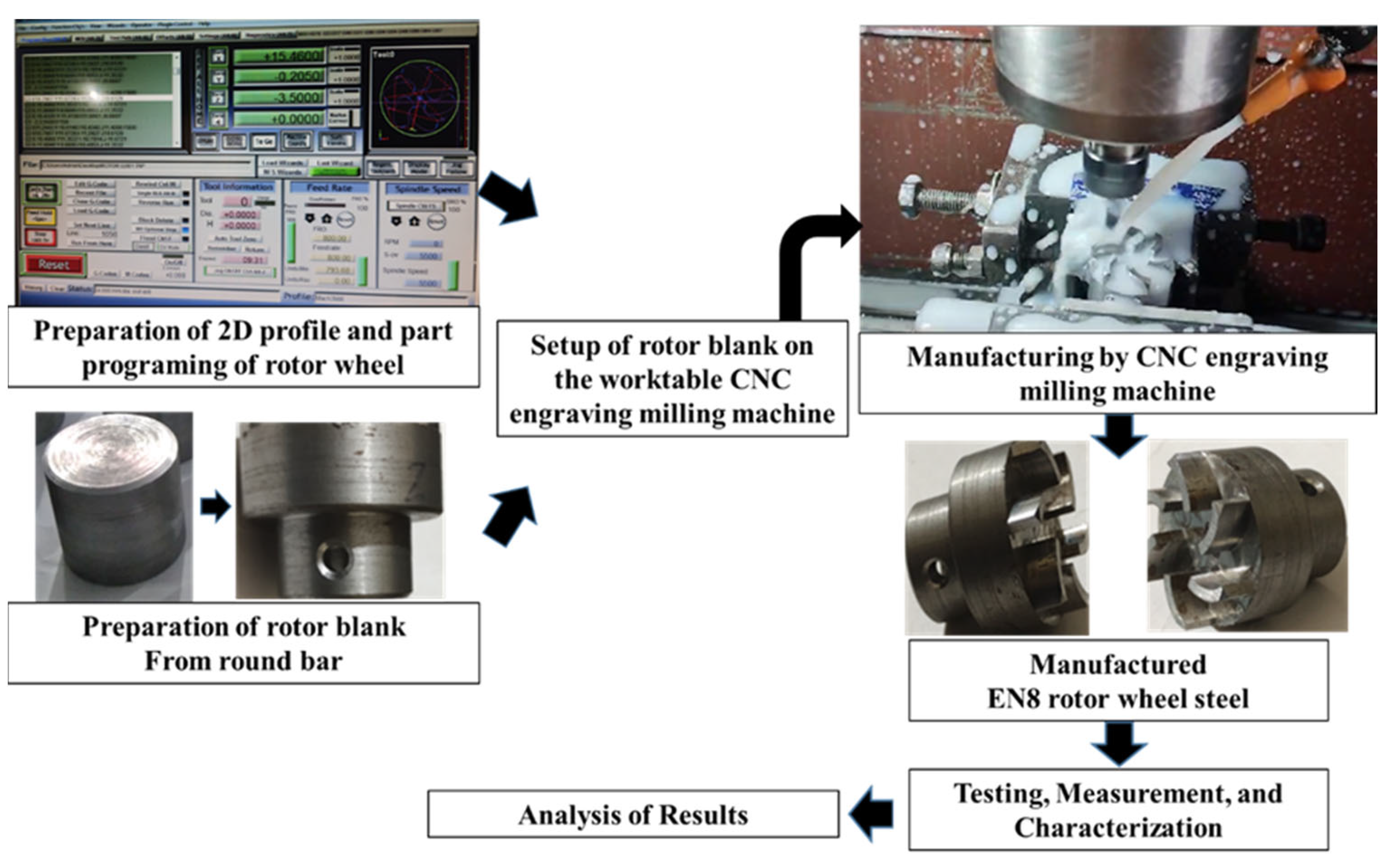
2.2. Procedure of Manufacturing the Small-Sized Stepped Rotor
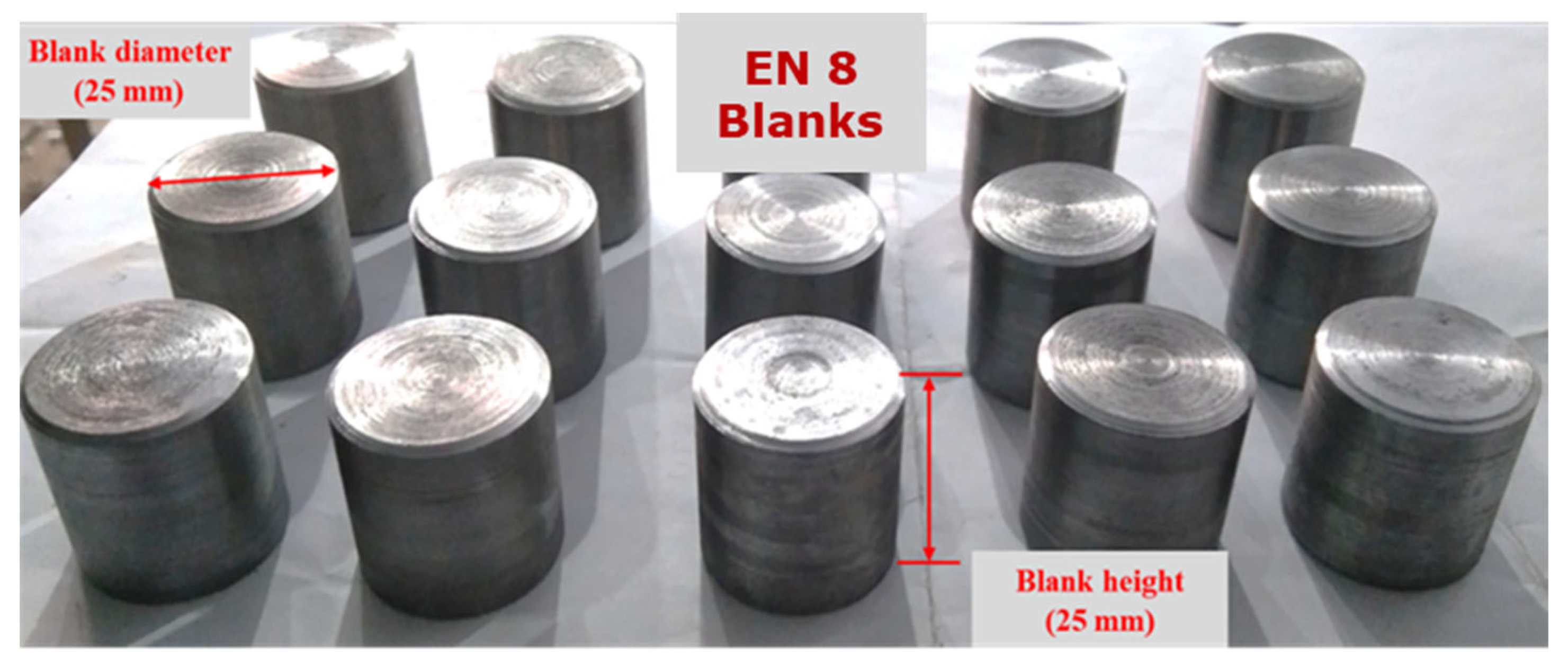
- Preparation of the blanks with a 25 mm diameter from the EN8 steel round bar using a manual lathe machine tool.
- The next step is the preparation of the stepped blank with a hub, bind bore, and screw hole from the blank by turning and drilling machining operations.
- After the preparation of the stepped blank, the next step is the preparation of a two-dimensional layout (Figure 3) of the semi-open-type stepped rotor with the help of AutoCAD 2023.
- The next step is the conversion of the AutoCAD-prepared two-dimensional geometrical layout of the rotor into a G-code and M-code part program.
- The next step is transferring the prepared part program to the CNC engraving milling machine with the help of a disk or pen drive.
- The next step is the referencing of the CNC engraving milling machine. CNC referencing is compulsory before starting the machining process in each experimental run.
- After that, the next step is clamping the designed fixture and V block on the worktable of the CNC engraving milling machine to firmly hold the stepped blank using screws.
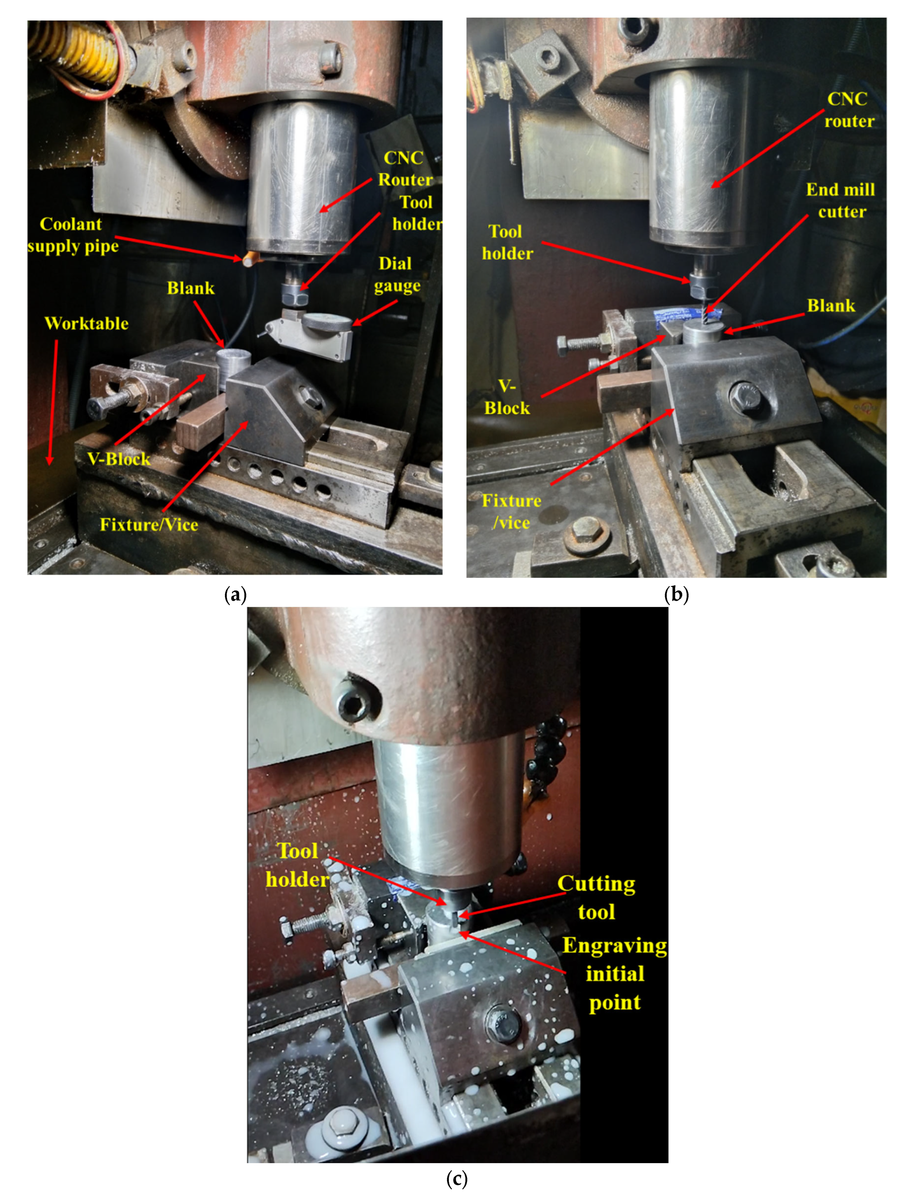
- The next step is ensuring the firm and appropriate positioning of the prepared stepped blank in the V block with the help of the dial gauge, as shown in Figure 4a. Minor variations in the positioning of the blank and flatness of the top surface significantly increase the noise and tool wear and reduce the dimensional accuracy as well as the surface quality of the manufactured turbine.
- The next step is the setting of the Z height of the cutting tool just above the top face of the blank with the help of a special gauge for safety purposes, as shown in Figure 4b. It prevents the cutting tool from coming in direct contact with the blank for machining. The movement of the cutting tool will be stopped at this height before starting the machining to avoid any risk of damage due to program or operator error.
- The window-based Mac 3 software is incorporated with the used CNC-EMM approach to read the part program and direct the cutting tool movement on the desired path of the part program.
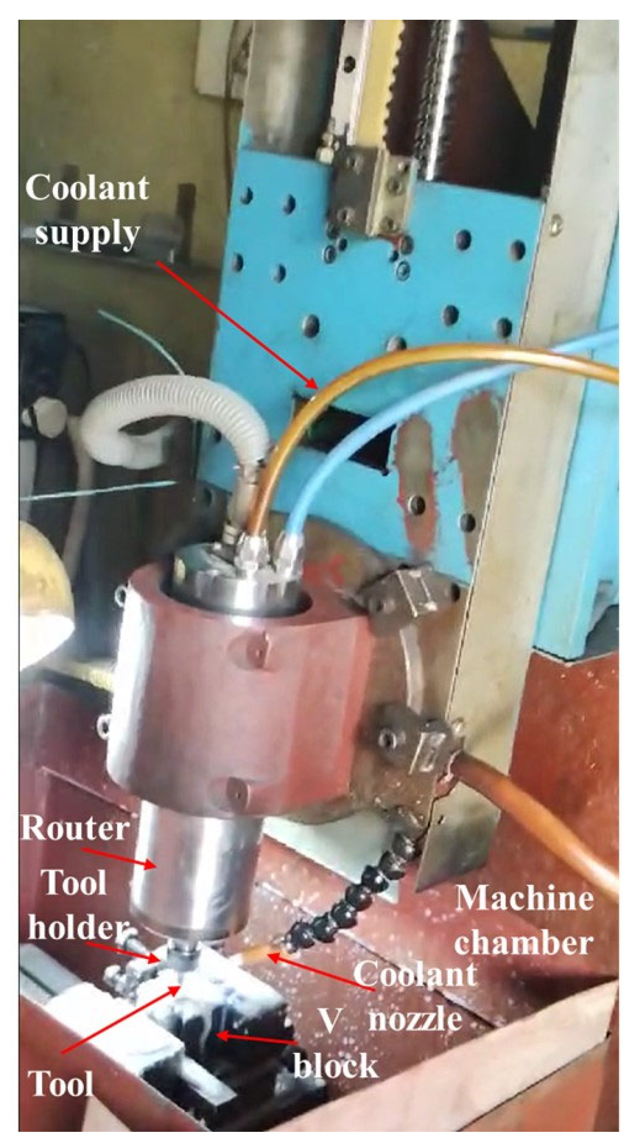
- Machining initiates with cutting and preparing the exact periphery as per the part program shown in Figure 4c. Cutting tools rotate in a clockwise direction.
- The small-sized stepped rotor is manufactured into three machining stages, known as the rough cut (RC), semi-finished cut (SFC), and finished cut (FC). A different part program was prepared for each stage.
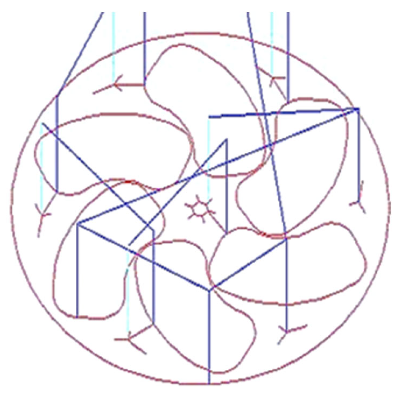
- The cutting tool rotates and moves in a clockwise direction during the engraving blade. The layout of the rotor blade and the direction of the tool path are shown in Figure 5. In each movement, the tool removes 50 µm of material in downward Z directions. Thus, the tool repeats the same path a hundred times to engrave a single blade with 5 mm height.
- Figure 6 shows the whole process sequence and engraving of the rotor blades by CNC-EMM.
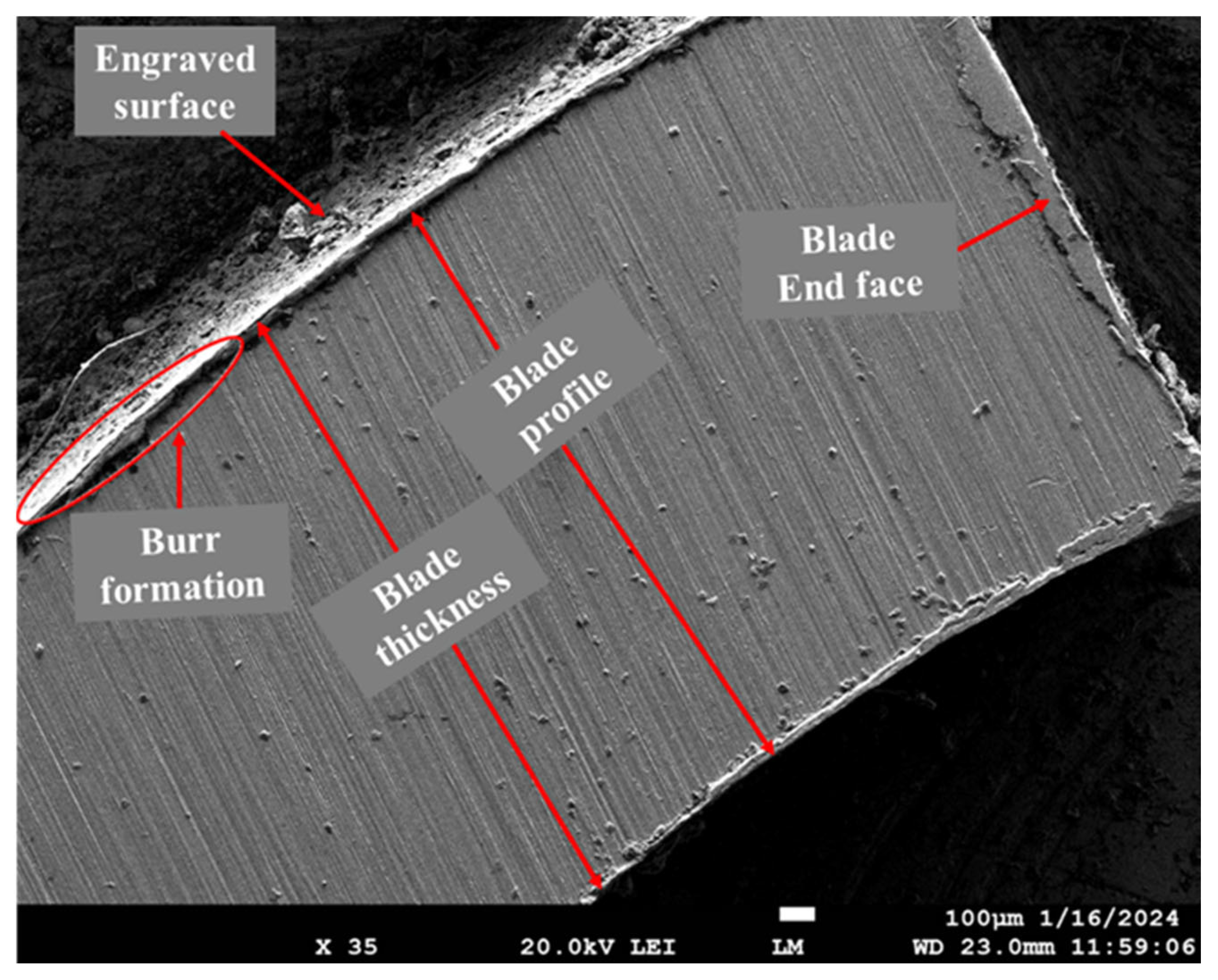
- After cutting the steeped rotor, the next step is to perform measurements of the average surface roughness and capture micrographs of the manufactured rotor blade using a field-emission scanning electron microscope (FE-SEM).
2.3. Experimentation and Measurements
3. Results and Discussion
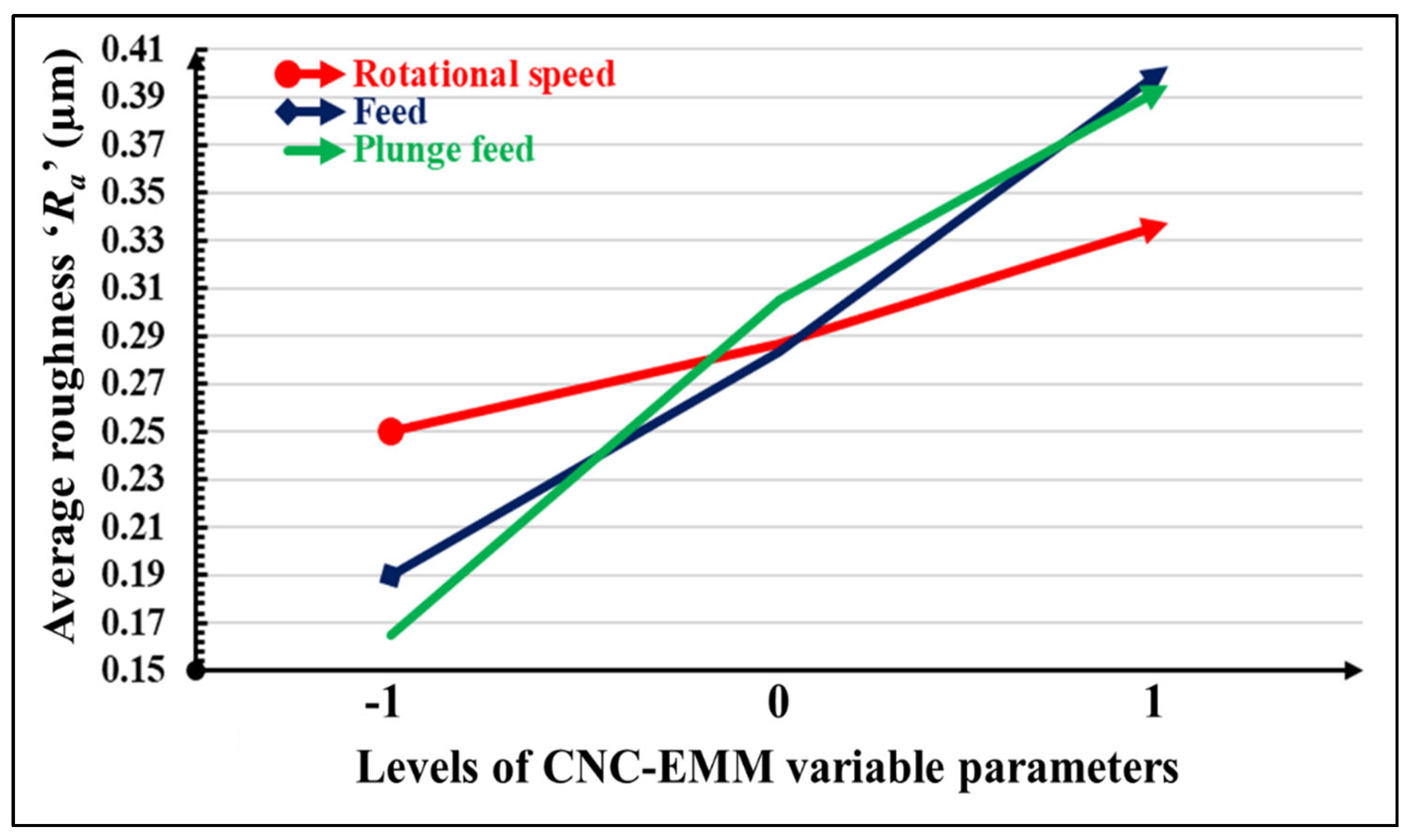
- The developed linear model of average roughness ‘Ra’ is significant as their ‘Prob > F’ (i.e., p values) is less than 0.05.
- Values of ‘Prob > F’ that are less than 0.05 indicate that the respective model terms are significant. Therefore, feed ‘f’ and plunge feed ‘Pf’ were found to be statistically significant for average roughness ‘Ra’.
- The F-value of 10.45 for average roughness ‘Ra’ suggests that the model is significant.
- The lack of fit F-values are non-significant relative to the pure error for average roughness ‘Ra’. The non-significant lack of fit is good and indicates that the developed model correctly fits the experimental data.
- Adequate precision indicates the signal-to-noise ratio, and its value being greater than four indicates an adequate signal. The value of adequate precision for Ra is 10.08.
- The residuals of each experiment are concentrated around the mean line (Figure 7). Therefore, they exhibit a normal distribution.
- The developed empirical equation 1 is linear (i.e., without square terms or interaction terms) and can be used for the future prediction of the values of average roughness ‘Ra’.
4. Conclusions
Author Contributions
Funding
Institutional Review Board Statement
Informed Consent Statement
Data Availability Statement
Acknowledgments
Conflicts of Interest
References
- Ahmad, F.; Kumar, P.; Patil, P.P.; Dobriyal, R.; Avikal, S. Comparative analysis of two and four blades Quadcopter propellers based on finite element method. Mater. Today Proc. 2023, in press. [Google Scholar] [CrossRef]
- Soori, M.; Asmael, M. Minimization of deflection error in five axis milling of impeller blades. Facta Univ. Ser. Mech. Eng. 2023, 21, 175–190. [Google Scholar] [CrossRef]
- Vdovin, R.A.; Smelov, V.G. Design and optimization of the micro-engine turbine rotor manufacturing using the rapid pro-totyping technology. IOP Conf. Ser. Mater. Sci. Eng. 2017, 177, 012040. [Google Scholar] [CrossRef]
- Geng, X.; Chi, G.; Wang, Y.; Wang, Z. High-efficiency Approach for Fabricating MTE Rotor by Micro-EDM and Mi-cro-extrusion. Chinese. J. Mech. Eng. 2014, 27, 830–835. [Google Scholar]
- Jain, N.K.; Chaubey, S.K. Review of Miniature Gear Manufacturing. In Comprehensive Materials Finishing; Hashmi, M.S.J., Ed.; Elsevier: Oxford, UK, 2016; Volume 1, pp. 504–538. [Google Scholar]
- Suharto, S.; Suryanto, S.; Sarana, S.; Purbono, K. Application of CNC machine router 3-Axis for making of Engraved granite or marble. IOP Conf. Ser. Mater. Sci. Eng. 2021, 1108, 012045. [Google Scholar] [CrossRef]
- Peng, T.-Y.; Shimoe, S.; Higo, M.; Kato, M.; Hirata, I.; Iwaguro, S.; Kaku, M. Effect of laser engraving on shear bond strength of polyetheretherketone to indirect composite and denture-base resins. J. Dent. Sci. 2024, 19, 32–38. [Google Scholar] [CrossRef] [PubMed]
- Martinov, G.M.; Obuhov, A.I.; Martinova, L.I.; Grigoriev, A.S. An Approach to Building a Specialized CNC System for Laser Engraving Machining. Procedia CIRP 2016, 41, 998–1003. [Google Scholar] [CrossRef]
- Kumar, P.J.; Tarun, A.S.S.; Gowtham, M.; Rao, P.T.; Yashwanth, G. Design and fabrication of portable laser cutting and en-graving machine. Int. J. Eng. Technol. 2018, 7, 570–573. [Google Scholar] [CrossRef]
- Lei, X.; Liu, S.; Wu, N.; Ge, Y.; Hou, H.; Liu, P. Experimental investigation of laser engraving quality on paper. Appl. Opt. 2020, 59, 2416–2421. [Google Scholar] [CrossRef] [PubMed]
- Durna, A.; Fries, J.; Hrabovsky, L.; Sliva, A.; Zarnovsky, J. Research and Development of Laser Engraving and Material Cutting Machine from 3D Printer. Manag. Syst. Prod. Eng. 2020, 28, 47–52. [Google Scholar] [CrossRef]
- Khalid, M.S.; Jaleed, S.M.; Zafar, A.; Khan, S.A.; Rehman, H.Z.U.; Khan, Z.H. Design and Experimental Verification of a Laser Engraving Machine. In Proceedings of the 2023 International Conference on Emerging Power Technologies (ICEPT), Topi, Pakistan, 6–7 May 2023; pp. 1–6. [Google Scholar]
- Lian, P.; Wen, Y.; Yu, P.; Ke, L.; Wei, L.; Hui, X. Research of PMAC-based open NC system for Engraving and milling machine. In Proceedings of the 2010 International Conference on Mechanic Automation and Control Engineering (MACE), Wuhan, China, 26–28 June 2010; pp. 3424–3427. [Google Scholar]
- Cao, S.K.; Sui, Z.M.; Liu, L.N.; Wang, G.C.; Song, W.W. Engraving and Milling Machine Design Based on Open CNC System. Appl. Mech. Mater. 2011, 52, 881–886. [Google Scholar] [CrossRef]
- Choudhary, R.; Titus, S.D.; Akshaya, P.; Mathew, J.A.; Balaji, N. CNC PCB milling and wood engraving machine. In Proceedings of the 2017 International Conference On Smart Technologies For Smart Nation (SmartTechCon), Bengaluru, India, 17–19 August 2017; pp. 1301–1306. [Google Scholar]
- Bangse, K.; Wibolo, A.; Wiryanta, I.K.E.H. Design and fabrication of a CNC router machine for wood engraving. J. Phys. Conf. Ser. 2020, 1450, 012094. [Google Scholar] [CrossRef]
- Kumar, J.; Singh, S.; Tripathi, S.; Shukla, V.; Pathak, S. Design and fabrication of 3-axis CNC milling machine using additive manufacturing. Mater. Today Proc. 2022, 68, 2443–2451. [Google Scholar] [CrossRef]
- Brenci, L.-M.; Gurău, L. A Stratified Characterization of Surface Quality of Beech Processed by Profile Milling. Appl. Sci. 2023, 14, 129. [Google Scholar] [CrossRef]
- Chandran, R.; Udhayaraj, S.; Eazhil, K.M. Effect of the heat-treatment process on the mechanical and microstructure properties of EN8 steel. Int. J. Surf. Engg. Interdiscip. Mater. Sci. 2022, 10, 1–12. [Google Scholar] [CrossRef]
- Schlegel, J. The World of Steel; Springer Nature: Berlin/Heidelberg, Germany, 2023. [Google Scholar]
- Bolton, W.; Higgins, R.A. Materials for Engineers and Technicians; Routledge: Abingdon, UK, 2020. [Google Scholar]
- Montgomery, D.C. Design and Analysis of Experiments, 10th ed.; John Willey and Sons: New York, NY, USA, 2019. [Google Scholar]
- Lorenzen, T.J.; Anderson, V.L. Design of Experiments; CRC Press: Boca Raton, FL, USA, 2019. [Google Scholar]
- Davim, J.P. Surface Integrity in Machining; Springer: Berlin/Heidelberg, Germany, 2010. [Google Scholar]
- Bhushan, B. Principles and Applications of Tribology; John Wiley & Sons: Hoboken, NJ, USA, 2013. [Google Scholar]
- Moodie, P.F.; Johnson, D.E. Applied Regression and ANOVA Using SAS; Chapman and Hall/CRC: Boca Raton, FL, USA, 2022. [Google Scholar]
- Herzog, M.H.; Francis, G.; Clarke, A.; ANOVA. Understanding Statistics and Experimental Design; Springer: Cham, Switzerland, 2019. [Google Scholar]
- Sankar, S.; Jessin, T.A.; Naik, M.V. Modeling of EDM electrodes for development of LPOT turbine rotor and optimization of parameters for attenuate portioned electrode by Taguchi based Grey Relational Analysis. Int. J. Adv. Eng. Manag. Sci. 2016, 2, 239606. [Google Scholar]


| Expt. No. | CNC-EMM Variable Parameters | Response/Performance Measure | ||
|---|---|---|---|---|
| Rotational Speed ‘SR’ (rpm) | Feed ‘f’ (mm/min) | Plunge Feed ‘Pf’ (mm/min) | Average Roughness ‘Ra’ (µm) | |
| 1 | 5500 | 800 | 125 | 0.11 |
| 2 | 5500 | 900 | 150 | 0.29 |
| 3 | 5500 | 900 | 100 | 0.15 |
| 4 | 5500 | 1000 | 125 | 0.45 |
| 5 | 6000 | 800 | 150 | 0.38 |
| 6 | 6000 | 800 | 100 | 0.14 |
| 7 | 6000 | 900 | 125 | 0.3 |
| 8 | 6000 | 900 | 125 | 0.29 |
| 9 | 6000 | 1000 | 100 | 0.17 |
| 10 | 6000 | 1000 | 150 | 0.44 |
| 11 | 6500 | 800 | 125 | 0.13 |
| 12 | 6500 | 900 | 150 | 0.47 |
| 13 | 6500 | 900 | 100 | 0.2 |
| 14 | 6500 | 1000 | 125 | 0.55 |
| Source | Sum of Squares | DF | Mean Squares | F-Value | p-Value (Prob > F) | Remarks |
|---|---|---|---|---|---|---|
| Model | 0.21 | 3 | 0.070 | 10.45 | 0.0020 | Significant |
| Rotating speed ‘SR’ | 0.015 | 1 | 0.015 | 2.27 | 0.1629 | Not significant |
| Feed ‘f’ | 0.090 | 1 | 0.090 | 13.39 | 0.0044 | Significant |
| Plunge feed ‘Pf’ | 0.11 | 1 | 0.11 | 15.68 | 0.0027 | Significant |
| Residual | 0.067 | 10 | 6.747 × 10⁻³ | |||
| Lack of Fit | 0.067 | 9 | 7.491 × 10⁻³ | 149.82 | 0.0633 | Not significant |
| Pure Error | 5.000 × 10⁻⁵ | 1 | 5.000 × 10⁻⁵ | |||
| Cor Total | 0.28 | 13 |
Disclaimer/Publisher’s Note: The statements, opinions and data contained in all publications are solely those of the individual author(s) and contributor(s) and not of MDPI and/or the editor(s). MDPI and/or the editor(s) disclaim responsibility for any injury to people or property resulting from any ideas, methods, instructions or products referred to in the content. |
© 2024 by the authors. Licensee MDPI, Basel, Switzerland. This article is an open access article distributed under the terms and conditions of the Creative Commons Attribution (CC BY) license (https://creativecommons.org/licenses/by/4.0/).
Share and Cite
Chaubey, S.K.; Gupta, K. Development of an EN8 Steel Stepped Rotor by a Novel Engraving Milling Technique. Materials 2024, 17, 1588. https://doi.org/10.3390/ma17071588
Chaubey SK, Gupta K. Development of an EN8 Steel Stepped Rotor by a Novel Engraving Milling Technique. Materials. 2024; 17(7):1588. https://doi.org/10.3390/ma17071588
Chicago/Turabian StyleChaubey, Sujeet Kumar, and Kapil Gupta. 2024. "Development of an EN8 Steel Stepped Rotor by a Novel Engraving Milling Technique" Materials 17, no. 7: 1588. https://doi.org/10.3390/ma17071588