

Microstructure Evolution and Fretting Wear Mechanisms of Steels Undergoing Oscillatory Sliding Contact in Dry Atmosphere


Abstract
1. Introduction
2. Materials and Experimental Methods
2.1. Specimens
2.2. Mechanical Testing
2.3. Surface Profilometry
2.4. Microanalytical Methods
3. Results
3.1. Friction
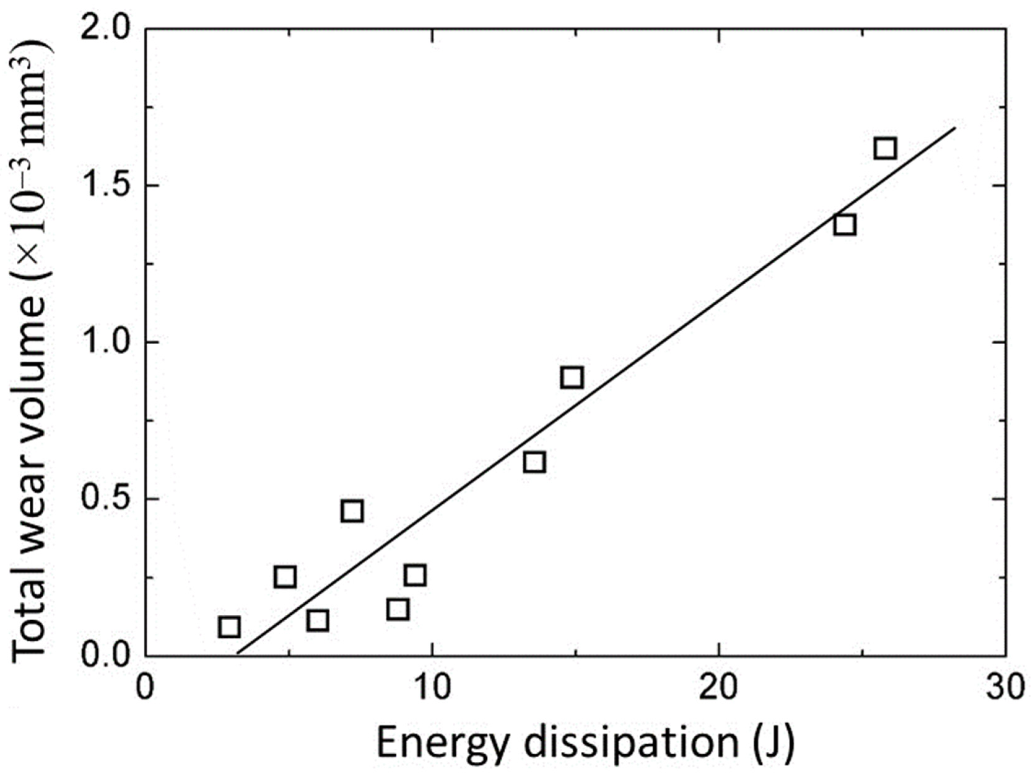
3.2. Wear
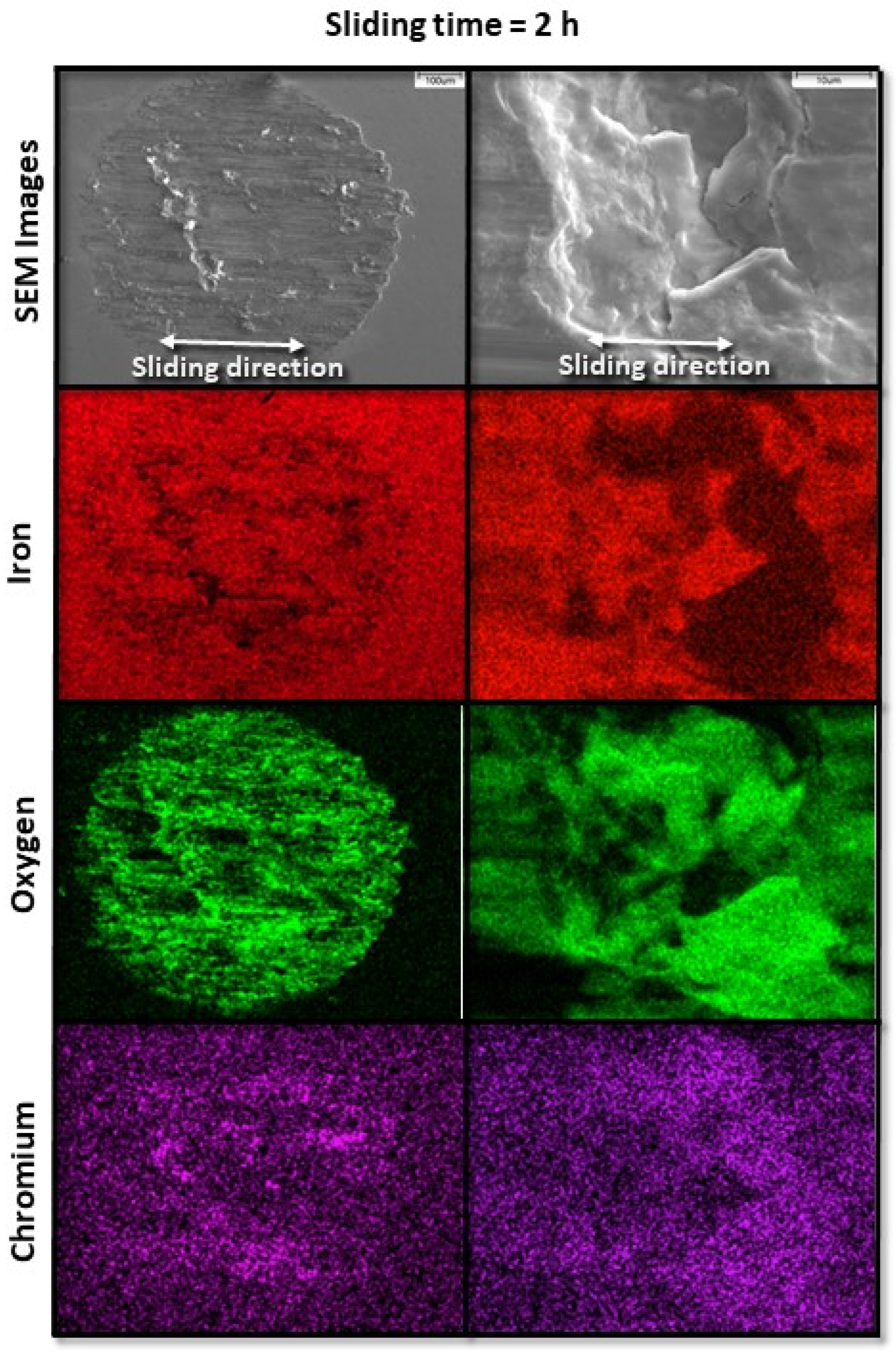
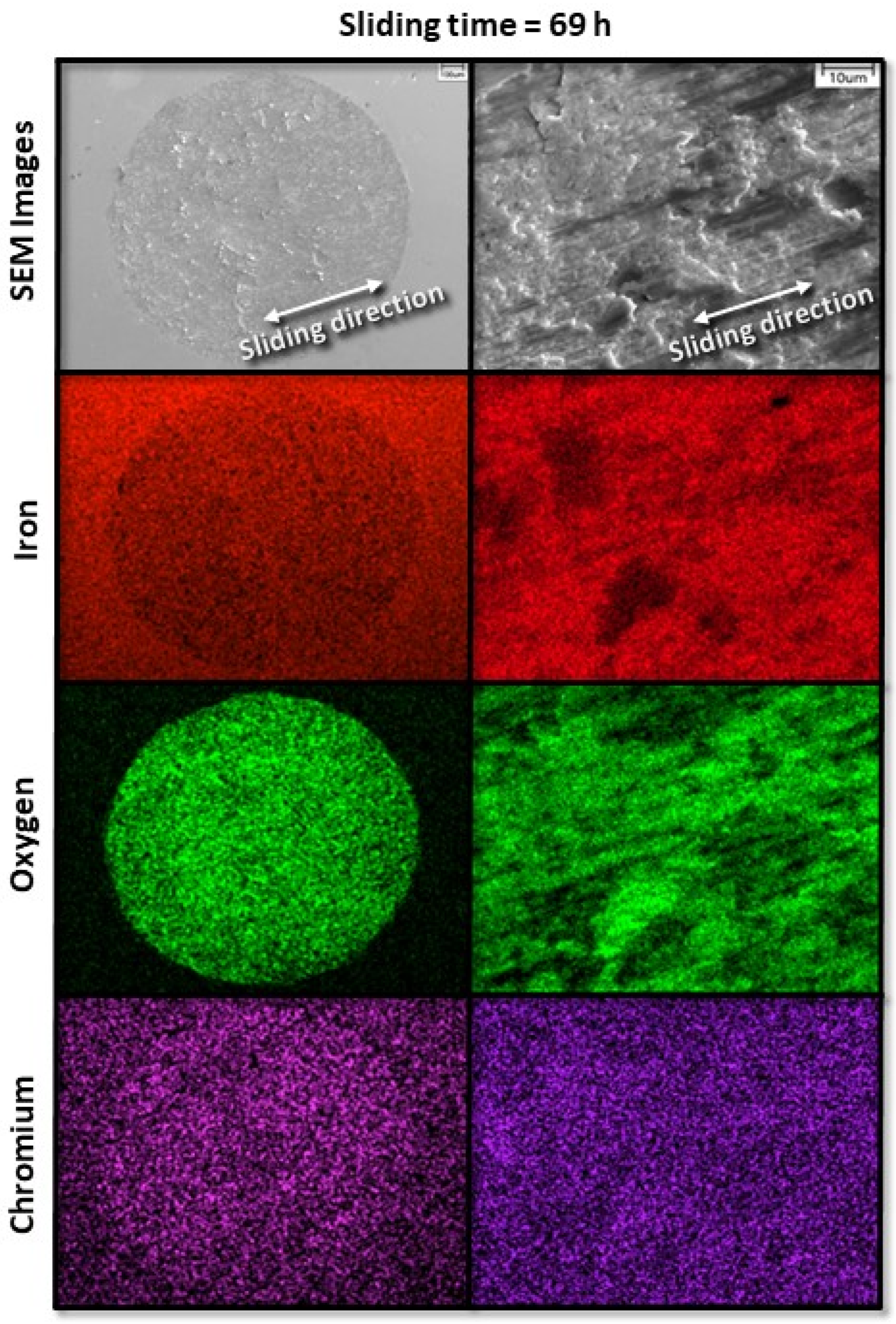
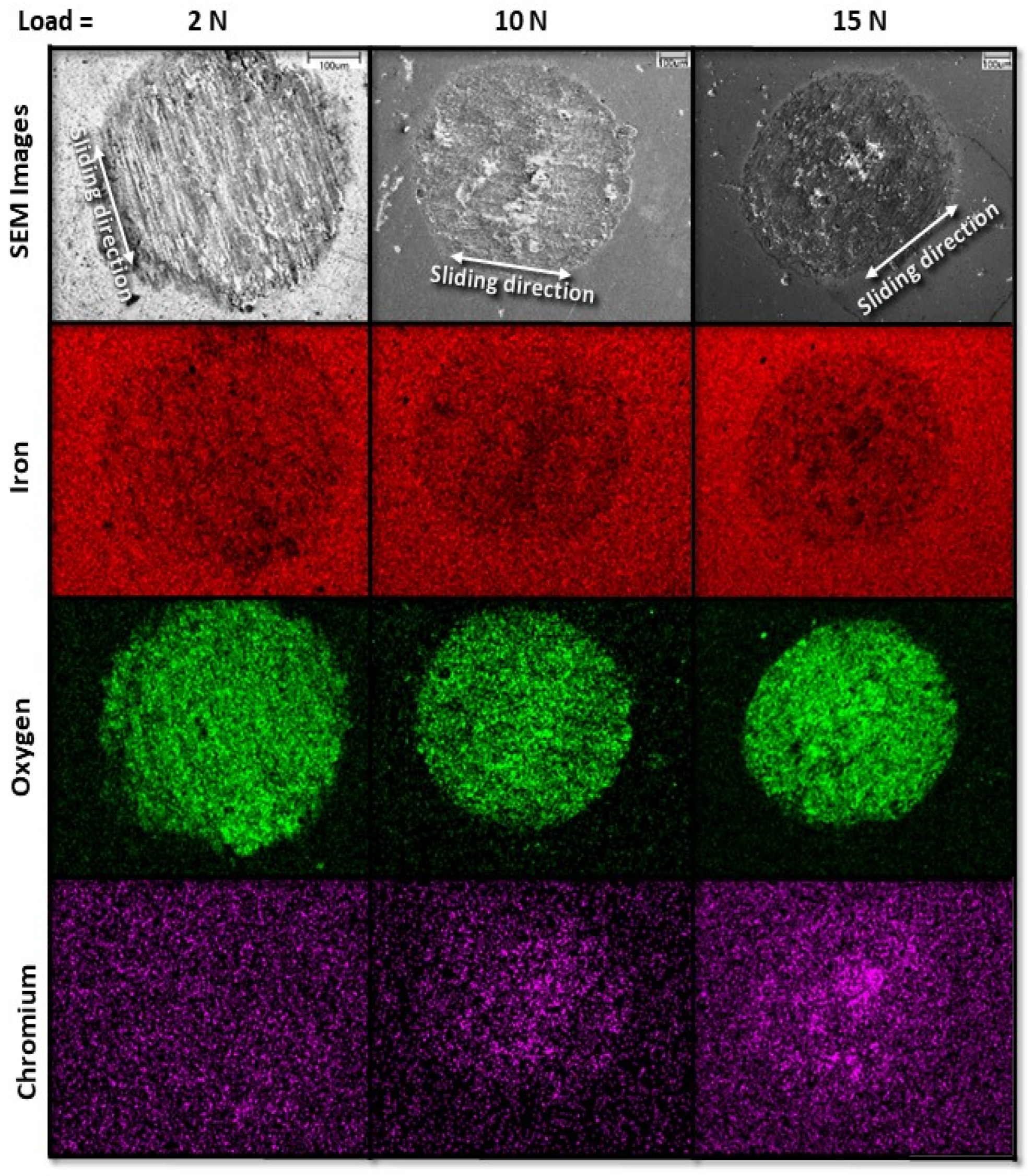
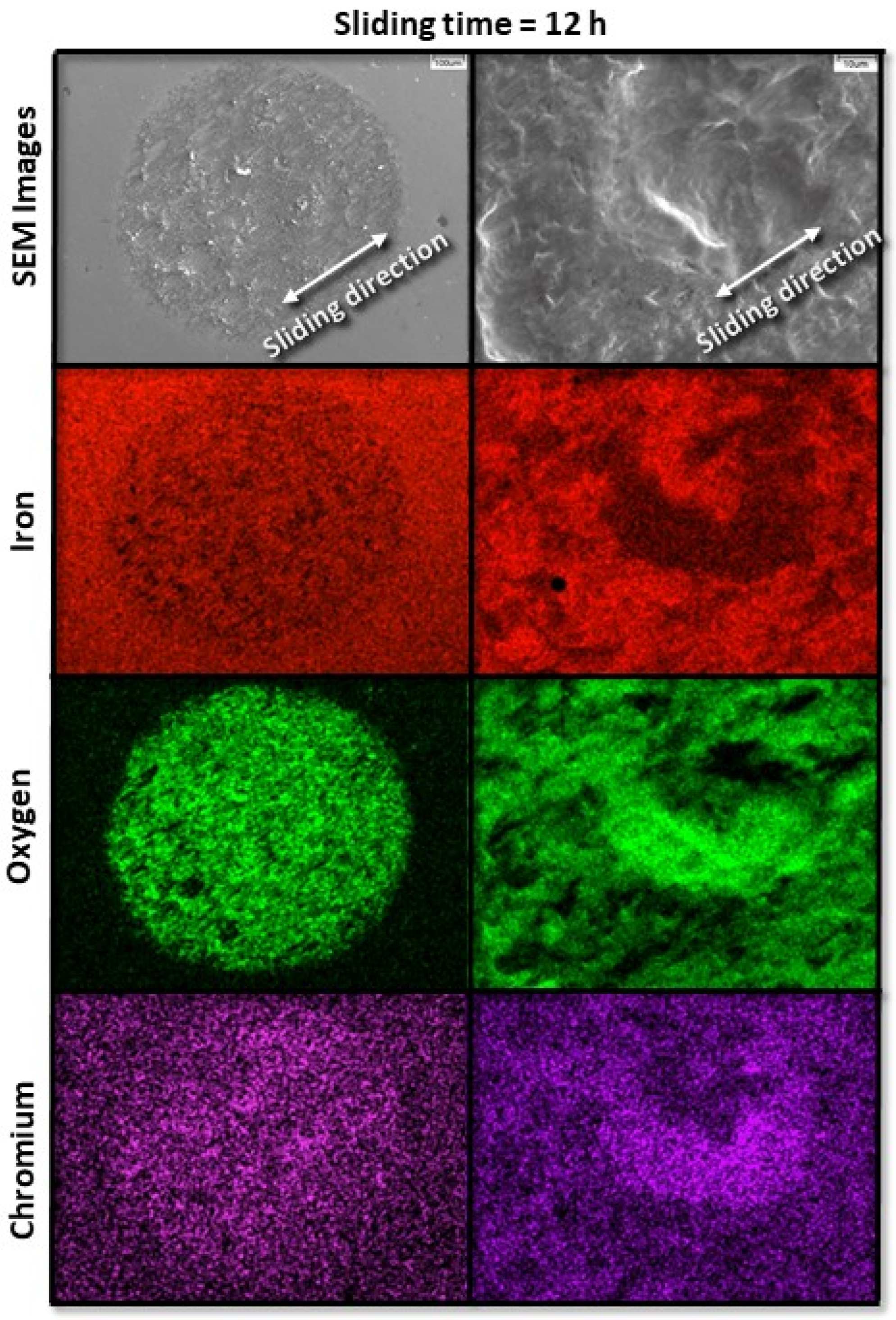
3.3. Surface Wear Characteristics
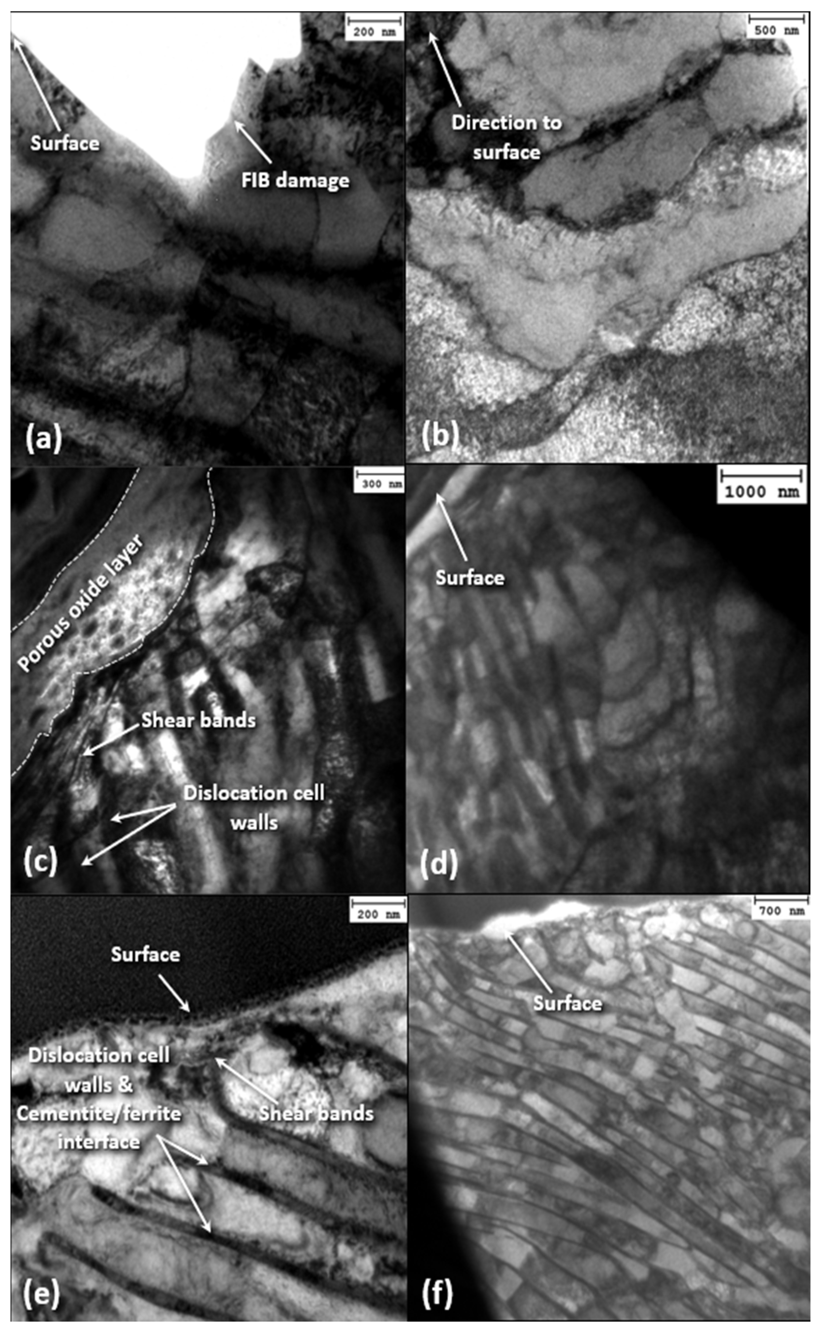
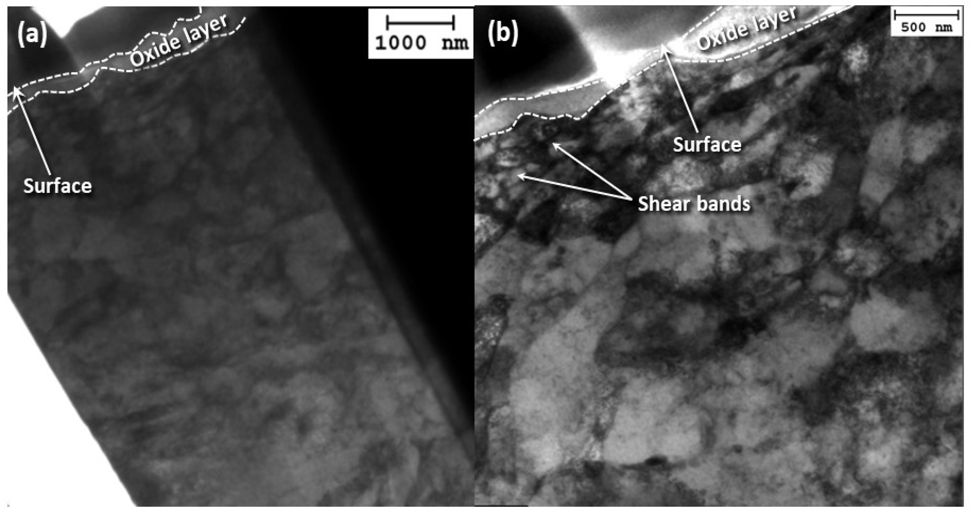
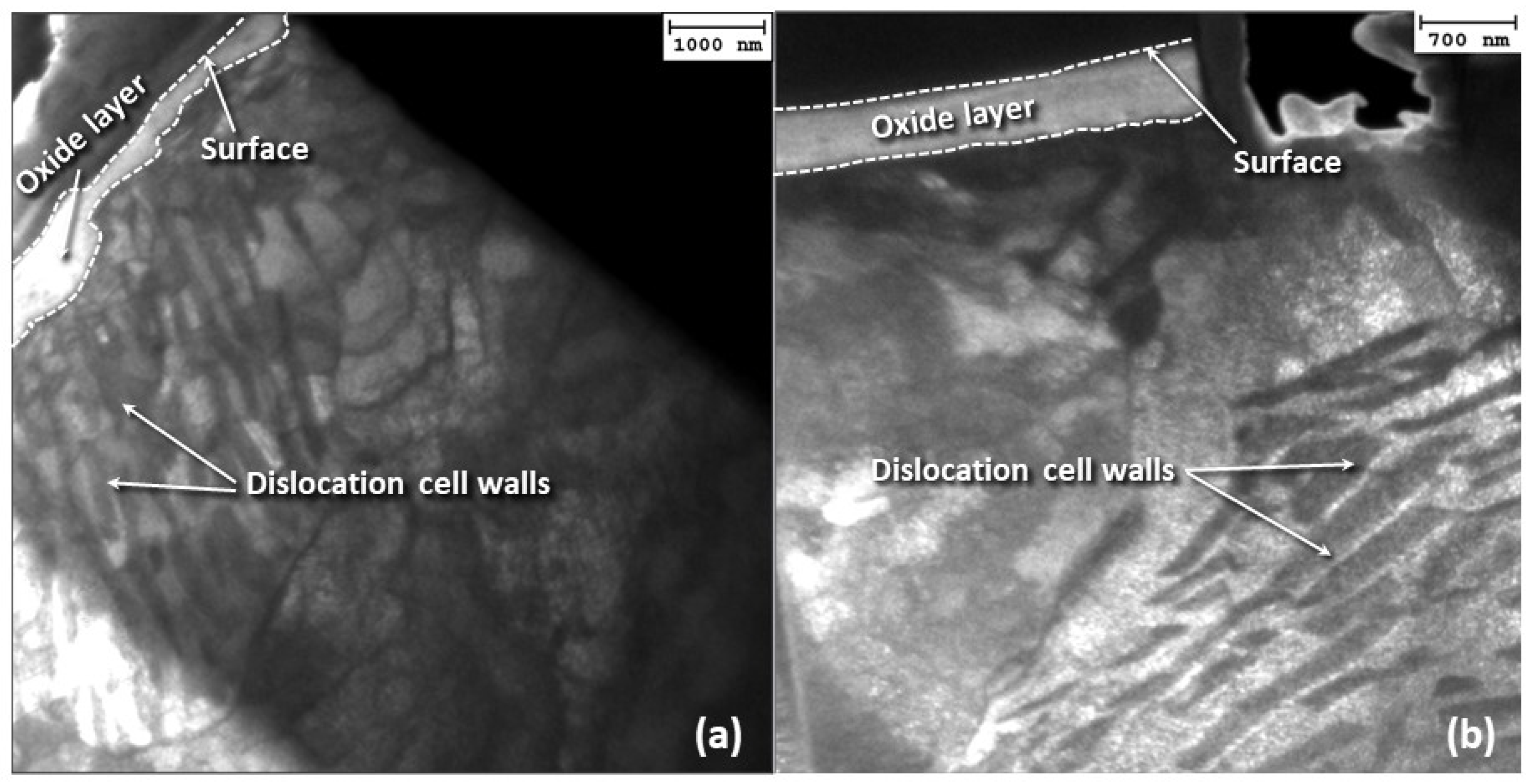
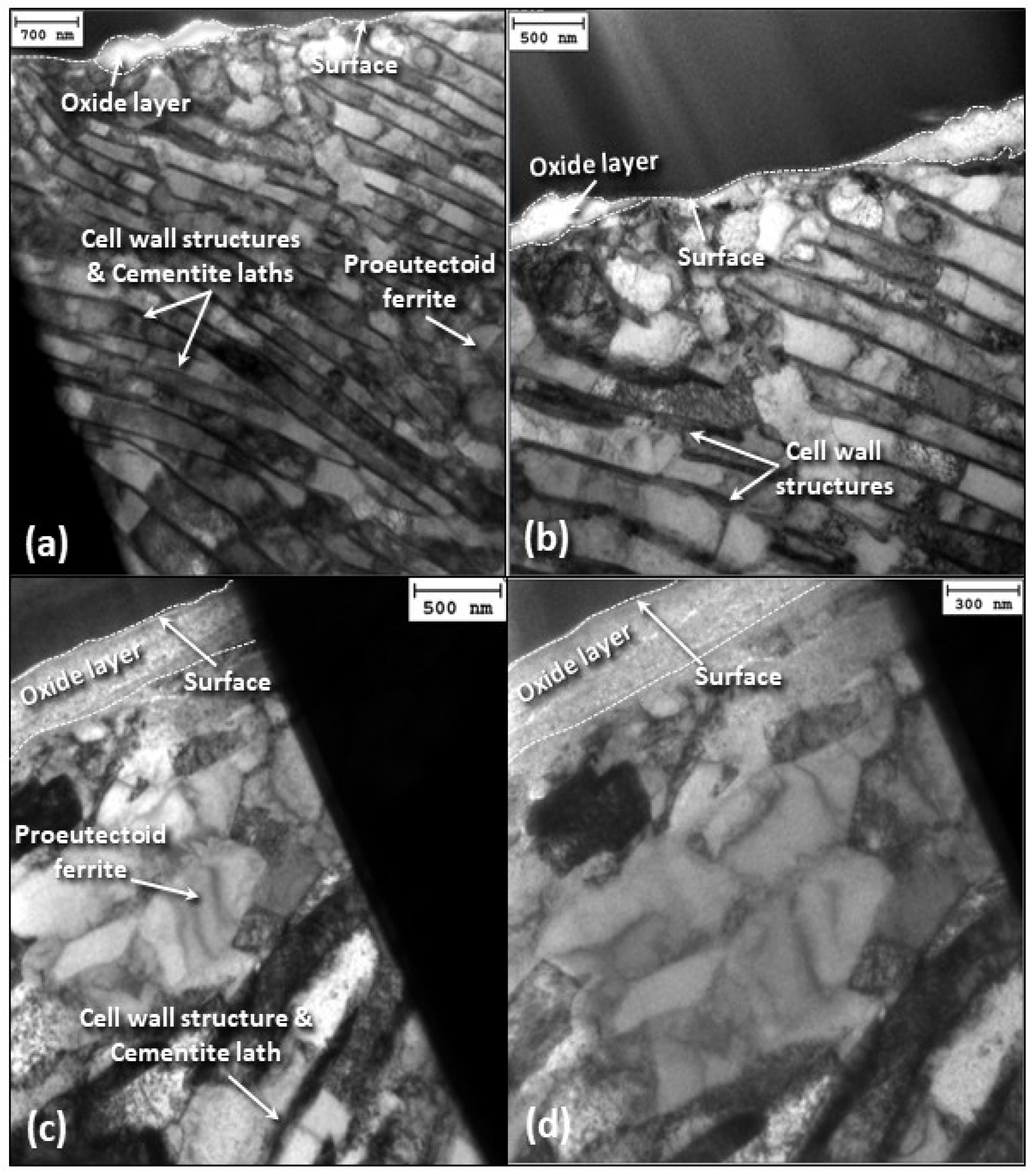
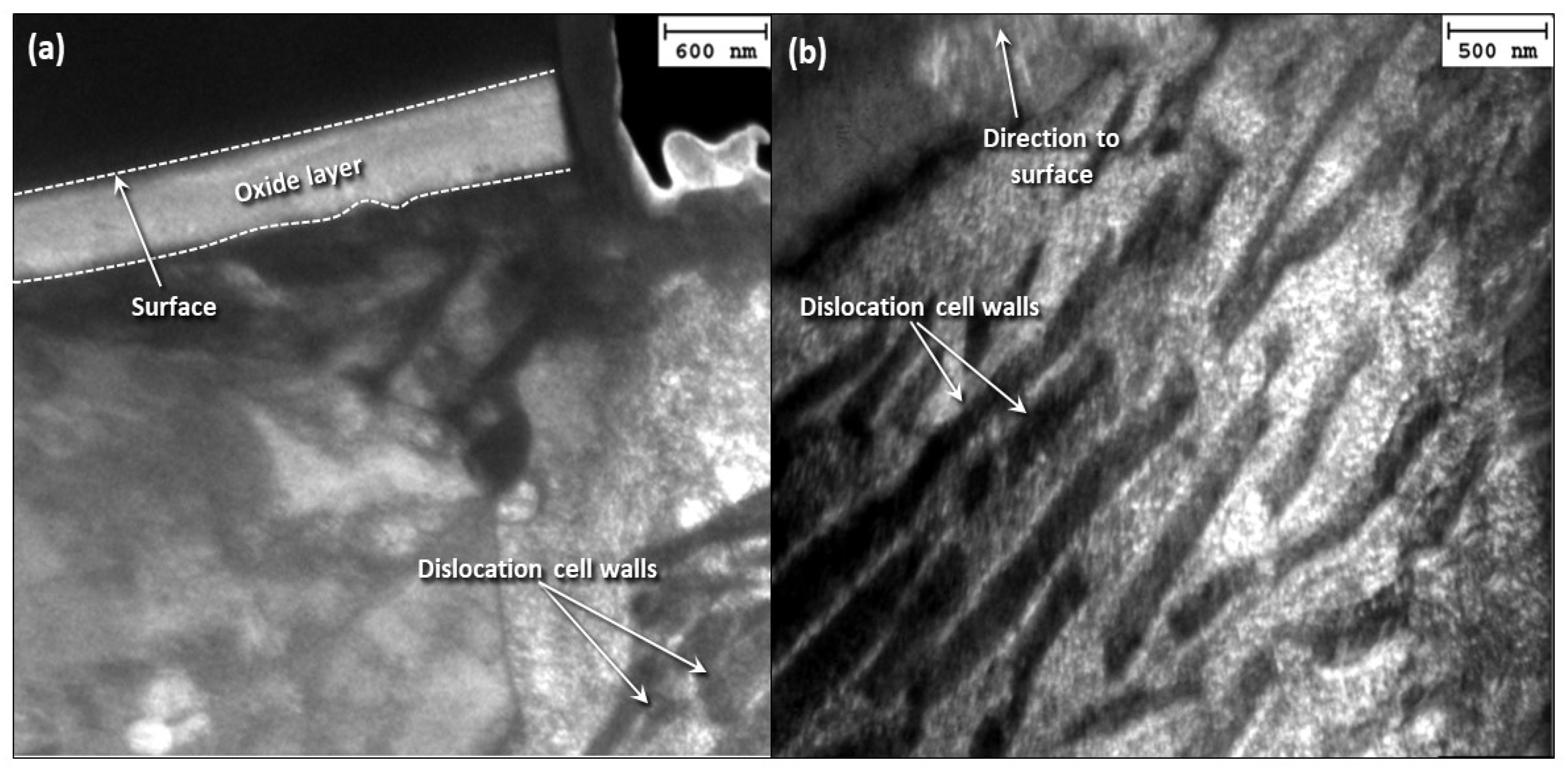
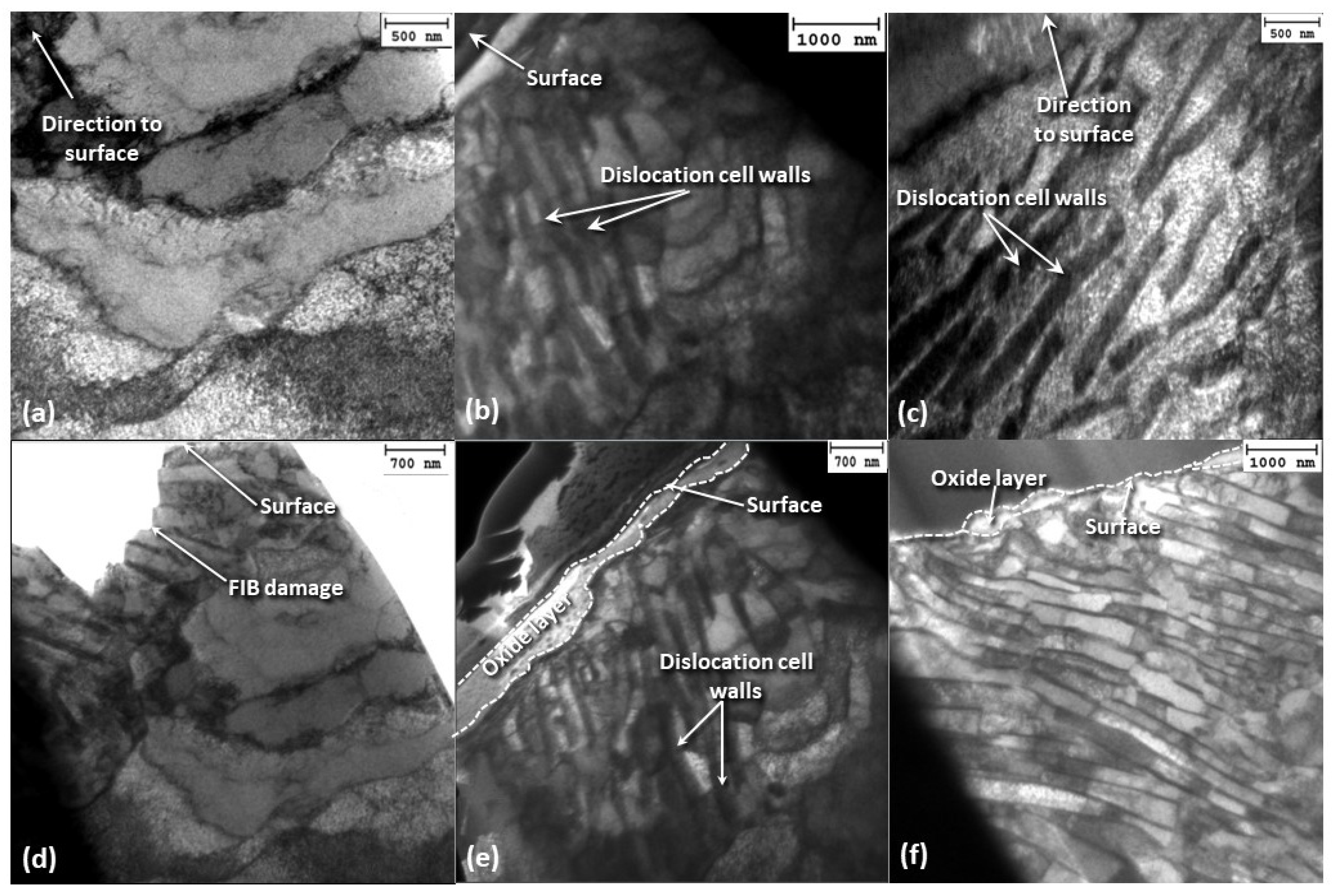
3.4. Subsurface Wear Characteristics
4. Discussion
4.1. Dislocation Cells/Persistent Slip Bands
4.2. Microstructure Evolution
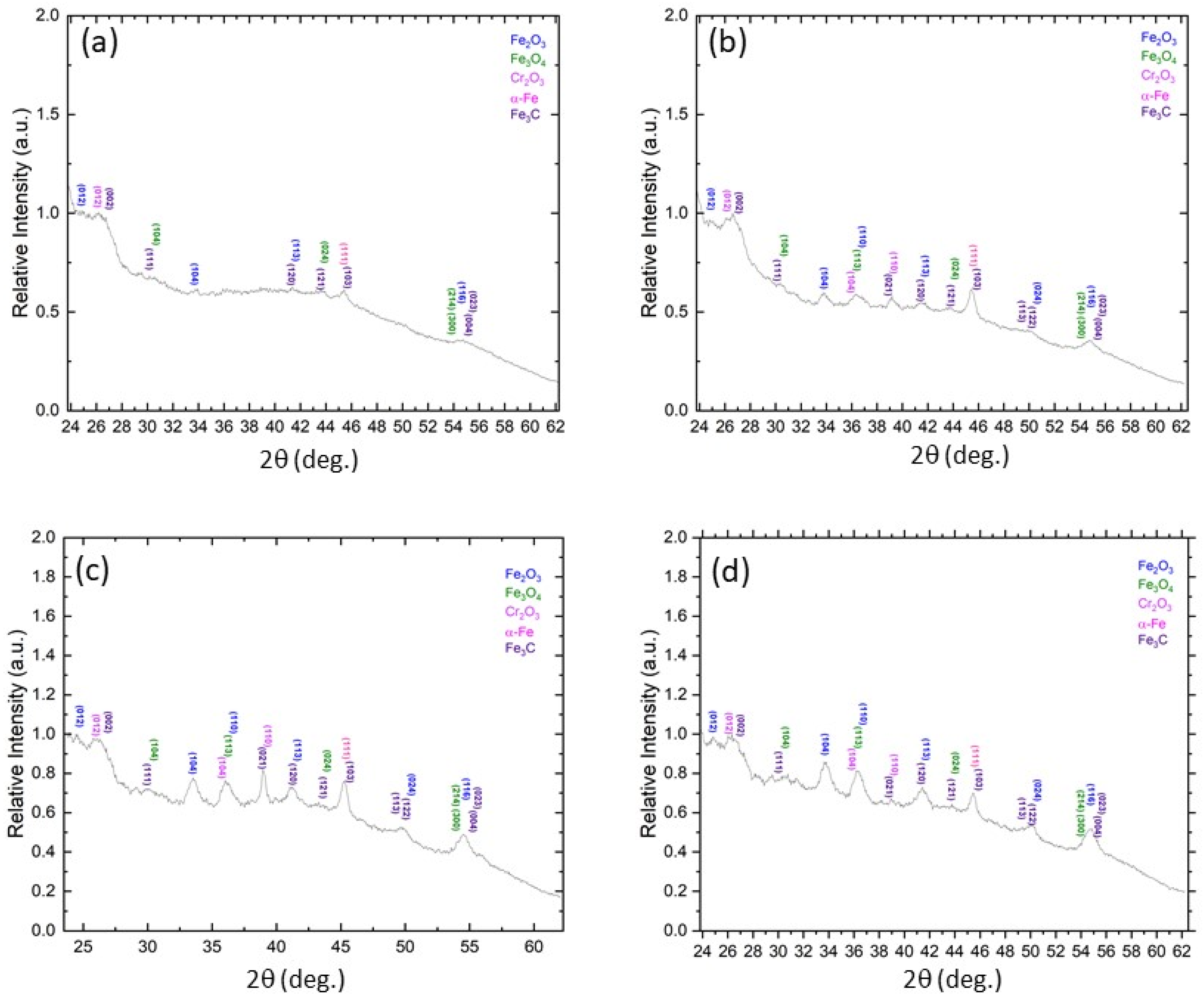
4.3. Oxidative Wear
4.4. Material Transfer
5. Conclusions
Author Contributions
Funding
Institutional Review Board Statement
Informed Consent Statement
Data Availability Statement
Acknowledgments
Conflicts of Interest
References
- Burwell, J.T., Jr. Survey of Possible Wear Mechanisms. Wear 1957, 1, 119–141. [Google Scholar] [CrossRef]
- Kato, K. Classification of Wear Mechanisms/Models. In Wear—Materials, Mechanisms and Practice; Stachowiak, G.W., Ed.; Wiley: Chichester, UK, 2005; pp. 9–20. [Google Scholar]
- Archard, J.F. Contact and Rubbing of Flat Surfaces. J. Appl. Phys. 1953, 24, 981–988. [Google Scholar] [CrossRef]
- Suh, N.P. The Delamination Theory of Wear. Wear 1973, 25, 111–124. [Google Scholar] [CrossRef]
- Davis, J.R. Surface Engineering for Corrosion and Wear Resistance; ASM International: Materials Park, OH, USA, 2001; Chapter 1; pp. 1–10. [Google Scholar]
- Evans, H.E. Stress Effects in High Temperature Oxidation of Metals. Int. Mater. Rev. 1995, 40, 1–40. [Google Scholar] [CrossRef]
- Perez, M. Gibbs–Thomson Effects in Phase Transformations. Scr. Mater. 2005, 52, 709–712. [Google Scholar] [CrossRef]
- Hanlumyuang, Y.; Gordon, P.A.; Neeraj, T.; Chrzan, D.C. Interactions Between Carbon Solutes and Dislocations in bcc Iron. Acta Mater. 2010, 58, 5481–5490. [Google Scholar] [CrossRef]
- Ventelon, L.; Lüthi, B.; Clouet, E.; Proville, L.; Legrand, B.; Rodney, D.; Willaime, F. Dislocation Core Reconstruction Induced by Carbon Segregation in bcc Iron. Phys. Rev. B 2015, 91, 220102. [Google Scholar] [CrossRef]
- Waterhouse, R.B. Fretting Wear. Wear 1984, 100, 107–118. [Google Scholar] [CrossRef]
- Waterhouse, R.B. Fretting Fatigue. Int. Mater. Rev. 1992, 37, 77–98. [Google Scholar] [CrossRef]
- Périer, V.; Dieng, L.; Gaillet, L.; Tessier, C.; Fouvry, S. Fretting-Fatigue Behaviour of Bridge Engineering Cables in a Solution of Sodium Chloride. Wear 2009, 267, 308–314. [Google Scholar] [CrossRef]
- Antler, M. Electrical Effects of Fretting Connector Contact Materials: A Review. Wear 1985, 106, 5–33. [Google Scholar] [CrossRef]
- Qian, L.; Zhou, Z.; Sun, Q.; Yan, W. Nanofretting Behaviors of NiTi Shape Memory Alloy. Wear 2007, 263, 501–507. [Google Scholar] [CrossRef]
- Berthier, Y.; Vincent, L.; Godet, M. Fretting Fatigue and Fretting Wear. Tribol. Int. 1989, 22, 235–242. [Google Scholar] [CrossRef]
- Hurricks, P.L. The Fretting Wear of Mild Steel from 200° to 500°C. Wear 1974, 30, 189–212. [Google Scholar] [CrossRef]
- Basu, B.; Vitchev, R.G.; Vleugels, J.; Celis, J.P.; Van Der Biest, O. Influence of Humidity on the Fretting Wear of Self-Mated Tetragonal Zirconia Ceramics. Acta Mater. 2000, 48, 2461–2471. [Google Scholar] [CrossRef]
- Mary, C.; Fouvry, S.; Martin, J.M.; Bonnet, B. Pressure and Temperature Effects on Fretting Wear Damage of a Cu-Ni-In Plasma Coating versus Ti17 Titanium Alloy Contact. Wear 2011, 272, 18–37. [Google Scholar] [CrossRef]
- Berthier, Y.; Vincent, L.; Godet, M. Velocity Accommodation in Fretting. Wear 1988, 125, 25–38. [Google Scholar] [CrossRef]
- Iwabuchi, A. The Role of Oxide Particles in the Fretting Wear of Mild Steel. Wear 1991, 151, 301–311. [Google Scholar] [CrossRef]
- Jiang, J.; Stott, F.H.; Stack, M.M. The Role of Triboparticulates in Dry Sliding Wear. Tribol. Int. 1998, 31, 245–256. [Google Scholar] [CrossRef]
- Stott, F.H. The Role of Oxidation in the Wear of Alloys. Tribol. Int. 1998, 31, 61–71. [Google Scholar] [CrossRef]
- Landolt, D.; Mischler, S.; Stemp, M. Electrochemical Methods in Tribocorrosion: A Critical Appraisal. Electrochim. Acta 2001, 46, 3913–3929. [Google Scholar] [CrossRef]
- Antler, M. Fretting of Electrical Contacts: An Investigation of Palladium Mated to Other Materials. Wear 1982, 81, 159–173. [Google Scholar] [CrossRef]
- Rybiak, R.; Fouvry, S.; Bonnet, B. Fretting Wear of Stainless Steels under Variable Temperature Conditions: Introduction of a ‘Composite’ Wear Law. Wear 2010, 268, 413–423. [Google Scholar] [CrossRef]
- Komvopoulos, K.; Saka, N.; Suh, N.P. The Significance of Oxide Layers in Boundary Lubrication. ASME J. Tribol. 1986, 108, 502–513. [Google Scholar] [CrossRef]
- Stott, F.H.; Glascott, J.; Wood, G.C. The Sliding Wear of Commercial Fe-12%Cr Alloys at High Temperature. Wear 1985, 101, 311–324. [Google Scholar] [CrossRef]
- Hansen, N. Microstructure and Flow Stress of Cell Forming Metals. Scr. Metal. Mater. 1992, 27, 947–950. [Google Scholar] [CrossRef]
- Yu, Q.; Mishra, R.K.; Morris, J.W., Jr.; Minor, A.M. The Effect of Size on Dislocation Cell Formation and Strain Hardening in Aluminium. Philo. Mag. 2014, 94, 2062–2071. [Google Scholar] [CrossRef]
- Kuhlmann-Wilsdorf, D. Q: Dislocations Structures—How Far from Equilibrium? A: Very Close Indeed. Mater. Sci. Eng. A 2001, 315, 211–216. [Google Scholar] [CrossRef]
- Mughrabi, H. Dislocation Wall and Cell Structures and Long-Range Internal Stresses in Deformed Metal Crystals. Acta Metal. 1983, 31, 1367–1379. [Google Scholar] [CrossRef]
- Jahanmir, S.; Suh, N.P.; Abrahamson, E.P. Microscopic Observations of the Wear Sheet Formation by Delamination. Wear 1974, 28, 235–249. [Google Scholar] [CrossRef]
- Kubaschewski, O.; Hopkins, B.E. Oxidation of Metals and Alloys, 2nd ed.; Butterworths: London, UK, 1962. [Google Scholar]
- Hauffe, K. Oxidation of Metals; Plenum Press: New York, NY, USA, 1965. [Google Scholar]
- Bruckman, A.; Simkovich, G. Concerning the Mechanism of Scale Growth due to Cation Diffusion in Fe2O3 and CuS. Corros. Sci. 1972, 12, 595–601. [Google Scholar] [CrossRef]
- Quinn, T.F.J.; Winer, W.O. An Experimental Study of the “Hot-Spots” Occurring During the Oxidational Wear of Tool Steel on Sapphire. ASME J. Tribol. 1987, 109, 315–319. [Google Scholar] [CrossRef]
- Hong, H.; Winer, W.O. A Fundamental Tribological Study of Ti/Al2O3 Contact in Sliding Wear. ASME J. Tribol. 1989, 111, 504–509. [Google Scholar] [CrossRef]
- Bogdanovich, P.N.; Tkachuk, D.V. Temperature Distribution over Contact Area and “Hot Spots” in Rubbing Solid Contact. Tribol. Int. 2006, 39, 1355–1360. [Google Scholar] [CrossRef]
- Sakrani, S.B.; Sullivan, J.L. Iron Oxide Films in Tribological Surfaces of Alloy Steel. In Proceedings of the 3rd International Conference on Thin Film Physics and Applications, Shanghai, China, 15–17 April 1997; Zhou, X., Wang, Y., Chen, Y.-X., Mao, S., Eds.; SPIE: Bellingham, WA, USA, 1998; Volume 3175, pp. 175–179. [Google Scholar]
- Rabinowicz, E. Friction and Wear of Materials, 2nd ed.; Wiley: New York, NY, USA, 2013. [Google Scholar]
- Komvopoulos, K. Adhesive Wear. In Handbook of Lubrication and Tribology, Volume II: Theory and Design, 2nd ed.; Bruce, R.W., Ed.; CRC Press: Boca Raton, FL, USA, 2012; Chapter 7; pp. 7-1–7-21. [Google Scholar]


| Element | Steel Composition (wt%) | |
|---|---|---|
| A216 Carbon Steel | 410 Stainless Steel | |
| Carbon | 0.25–0.3 | <0.15 |
| Chromium | 0.5 | 11.5–13.5 |
| Manganese | 0.7–1.2 | <1.0 |
| Phosphorous | 0.035 | <0.04 |
| Sulfur | 0.035 | <0.03 |
| Silicon | 0.6 | <1.0 |
Disclaimer/Publisher’s Note: The statements, opinions and data contained in all publications are solely those of the individual author(s) and contributor(s) and not of MDPI and/or the editor(s). MDPI and/or the editor(s) disclaim responsibility for any injury to people or property resulting from any ideas, methods, instructions or products referred to in the content. |
© 2024 by the authors. Licensee MDPI, Basel, Switzerland. This article is an open access article distributed under the terms and conditions of the Creative Commons Attribution (CC BY) license (https://creativecommons.org/licenses/by/4.0/).
Share and Cite
Maich, A.A.; Gronsky, R.; Komvopoulos, K. Microstructure Evolution and Fretting Wear Mechanisms of Steels Undergoing Oscillatory Sliding Contact in Dry Atmosphere. Materials 2024, 17, 1737. https://doi.org/10.3390/ma17081737
Maich AA, Gronsky R, Komvopoulos K. Microstructure Evolution and Fretting Wear Mechanisms of Steels Undergoing Oscillatory Sliding Contact in Dry Atmosphere. Materials. 2024; 17(8):1737. https://doi.org/10.3390/ma17081737
Chicago/Turabian StyleMaich, Alyssa A., Ronald Gronsky, and Kyriakos Komvopoulos. 2024. "Microstructure Evolution and Fretting Wear Mechanisms of Steels Undergoing Oscillatory Sliding Contact in Dry Atmosphere" Materials 17, no. 8: 1737. https://doi.org/10.3390/ma17081737
APA StyleMaich, A. A., Gronsky, R., & Komvopoulos, K. (2024). Microstructure Evolution and Fretting Wear Mechanisms of Steels Undergoing Oscillatory Sliding Contact in Dry Atmosphere. Materials, 17(8), 1737. https://doi.org/10.3390/ma17081737