
Experimental Investigation on Diamond Band Saw Processing of Resin Mineral Composites


Abstract
:1. Introduction
2. Materials and Methods
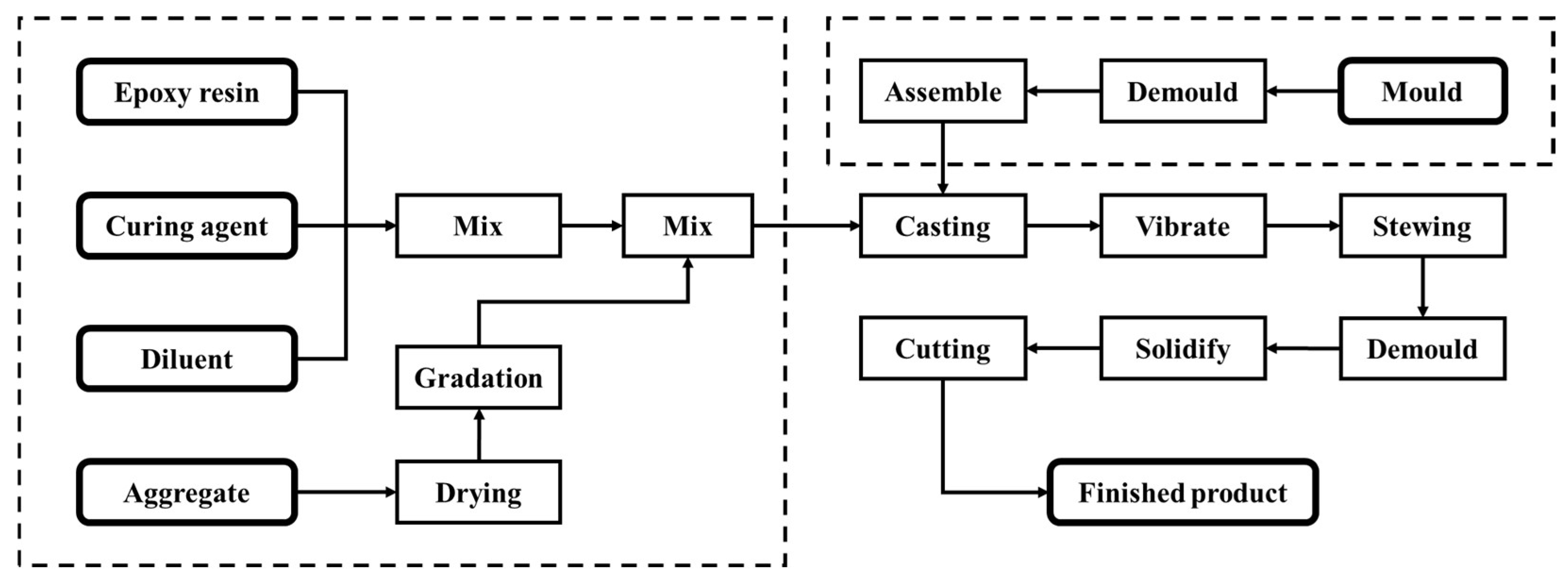
2.1. Materials
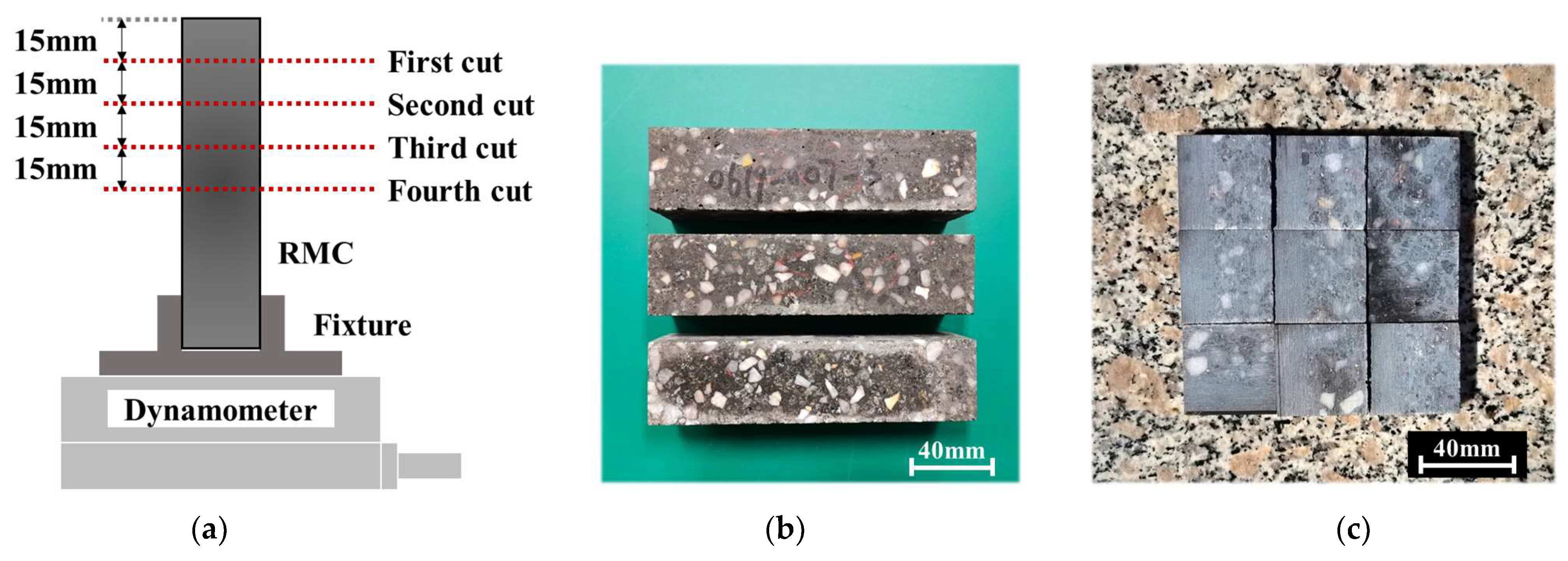
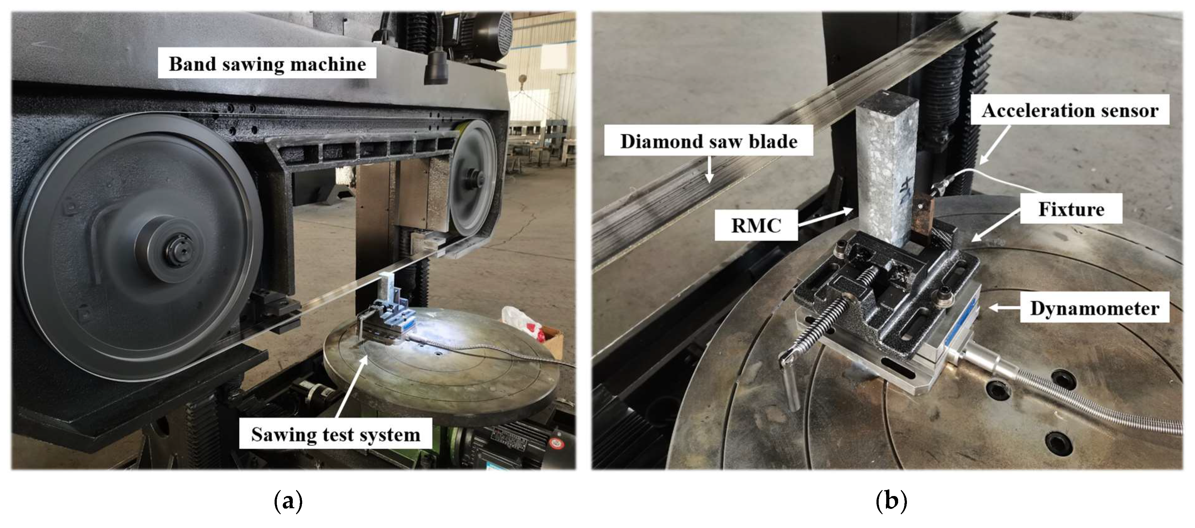
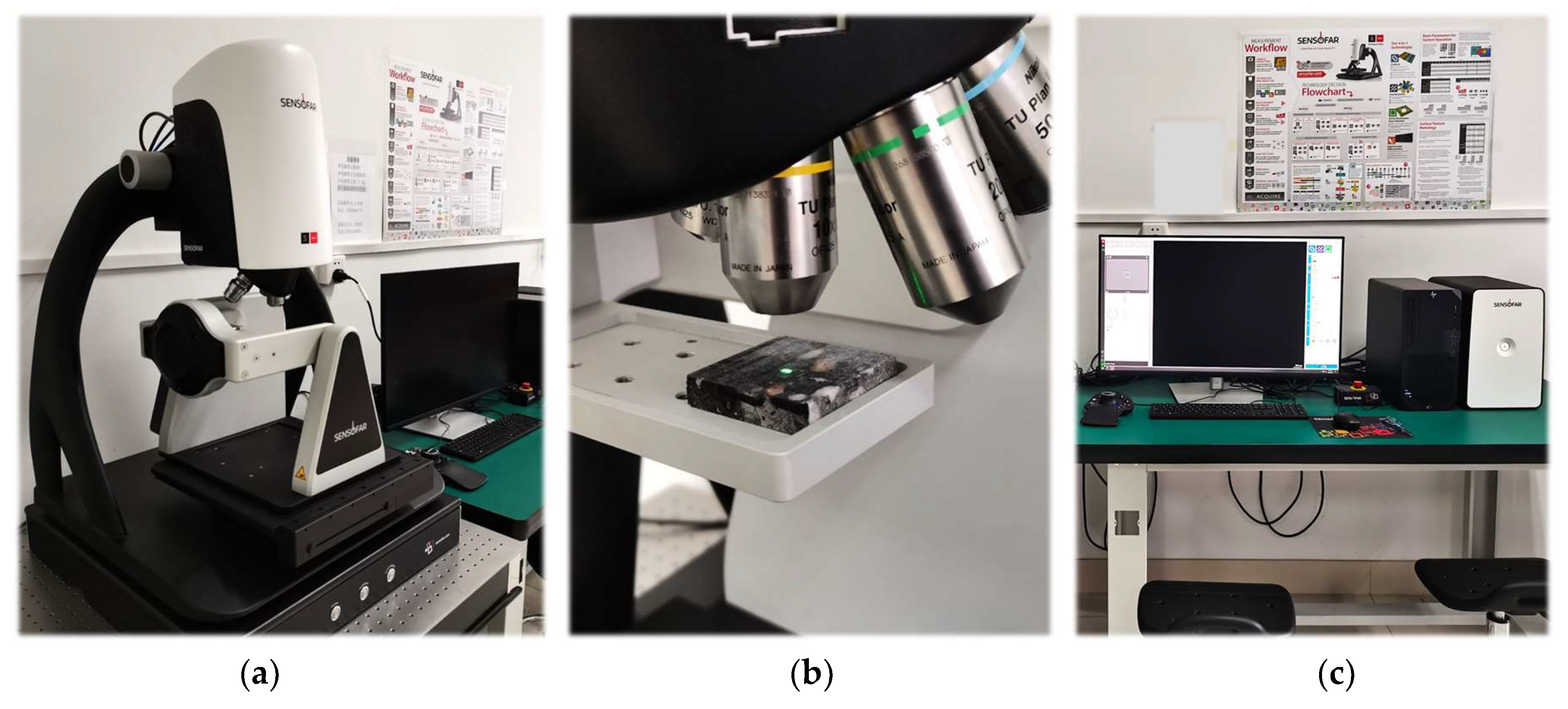
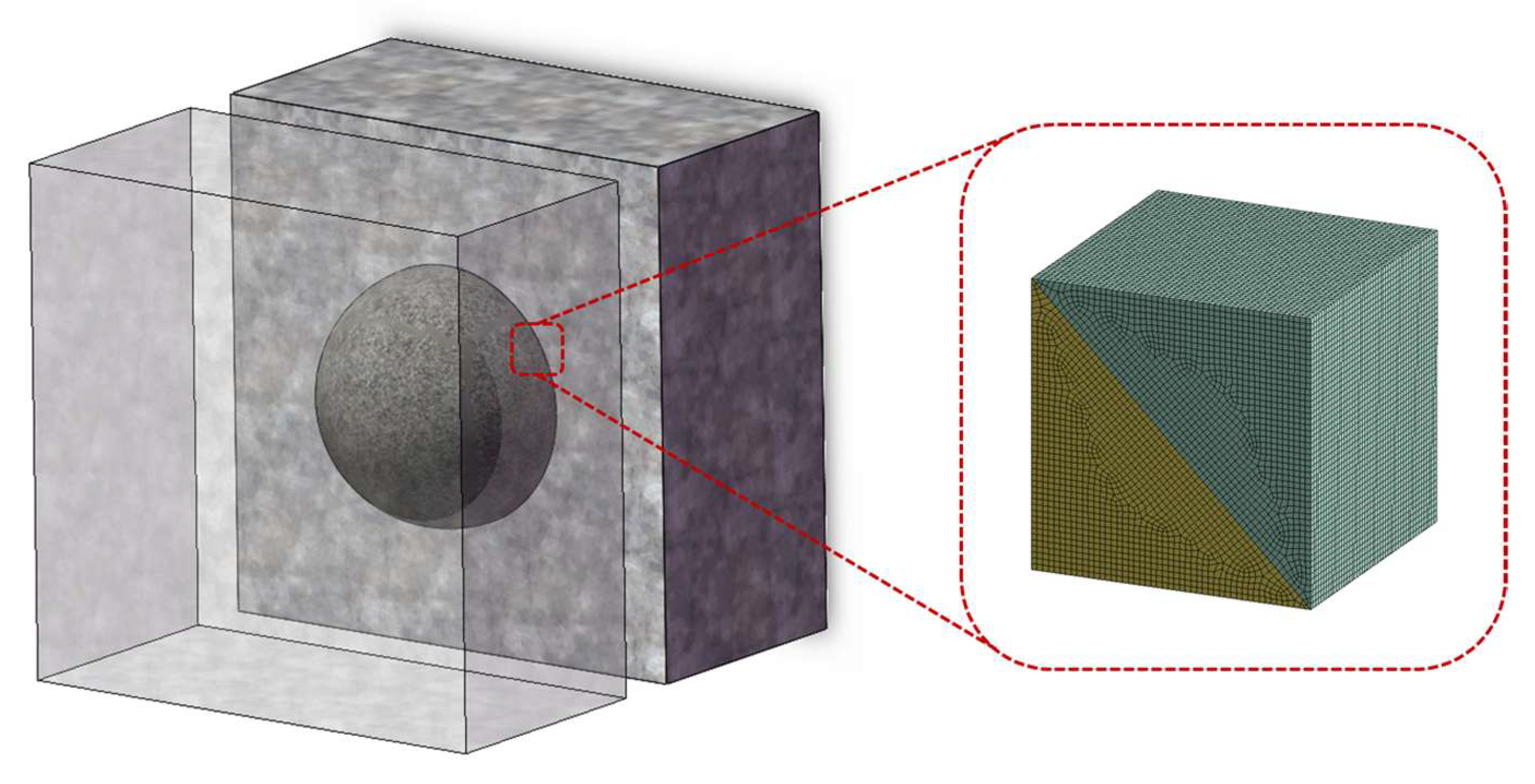
2.2. Experimental Method
3. Results
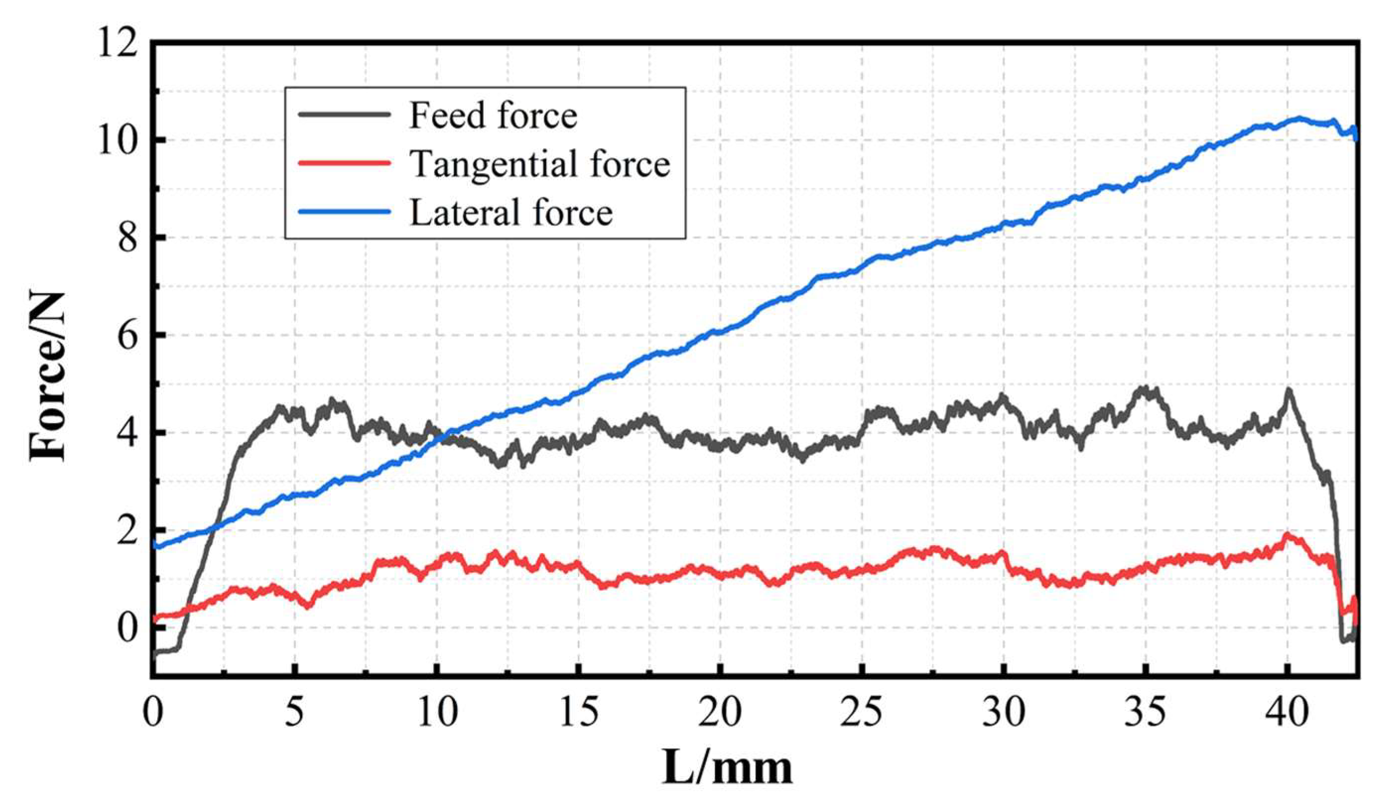
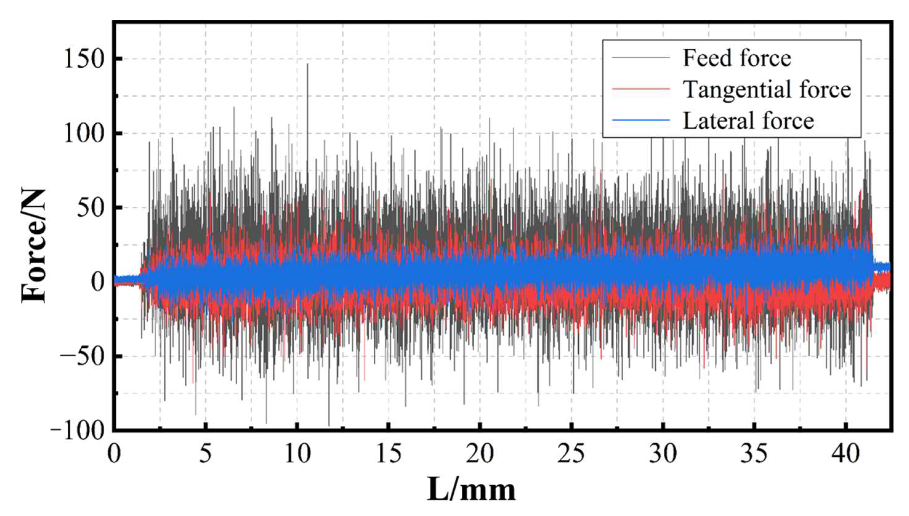
3.1. Sawing Force Characteristics
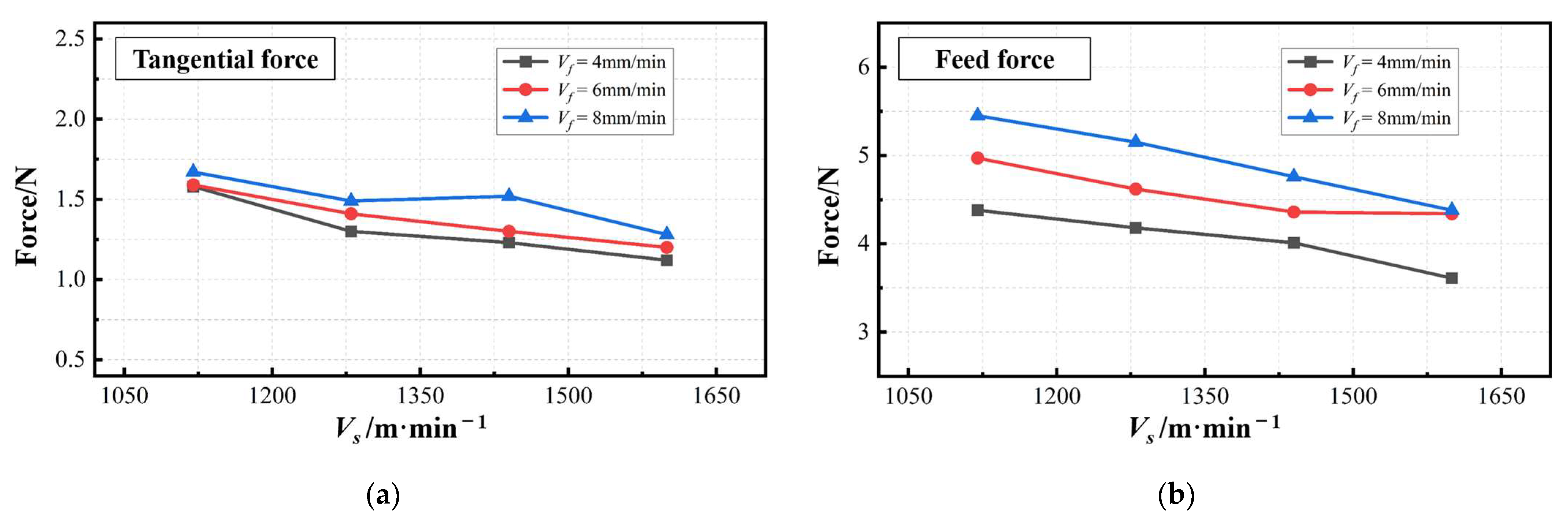
3.1.1. Characteristics of Tangential Force and Feed Force
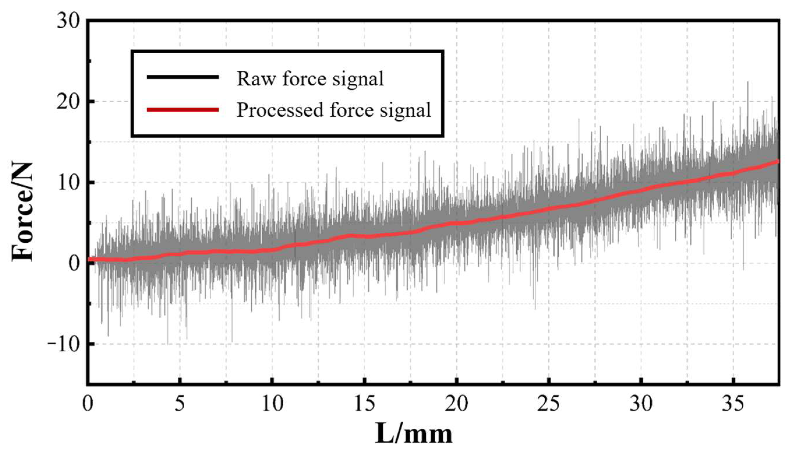
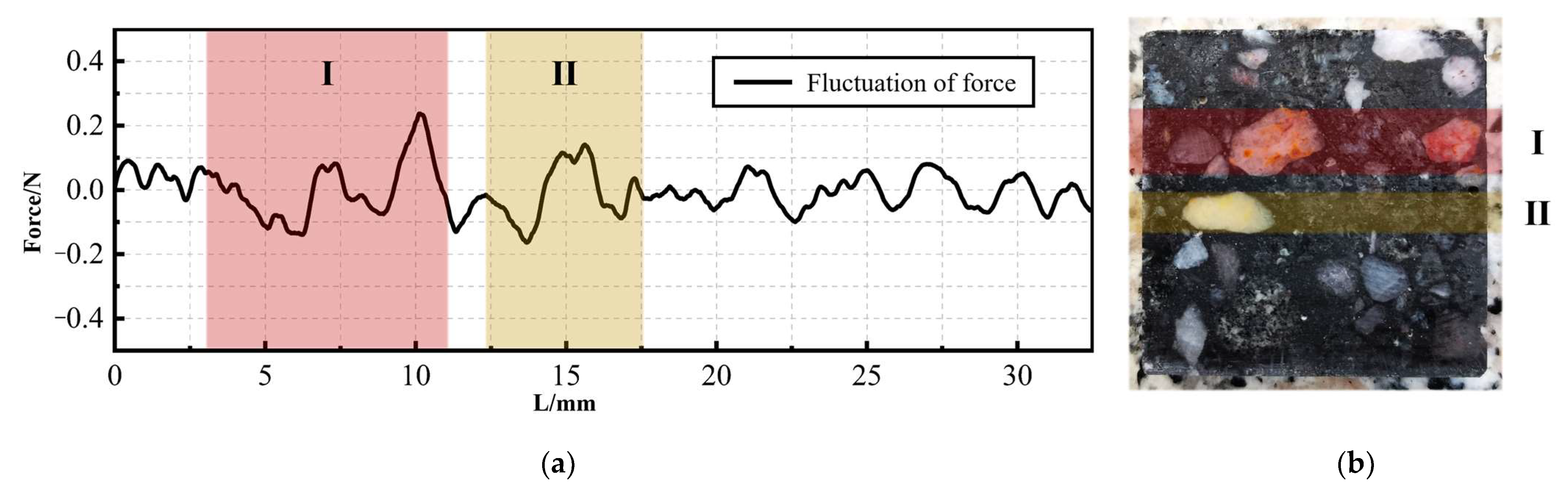
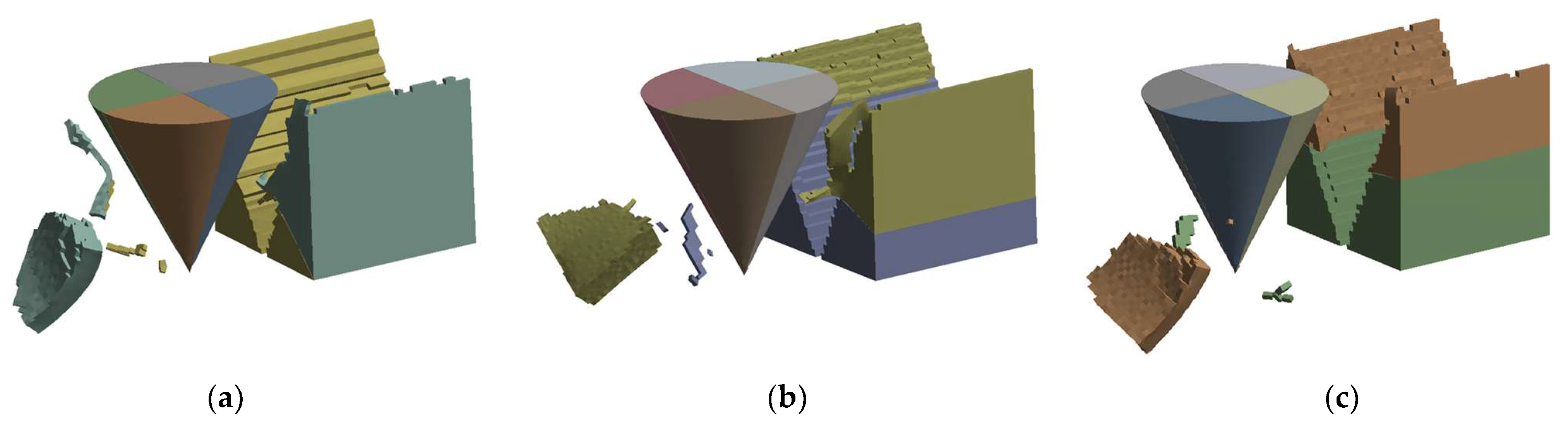
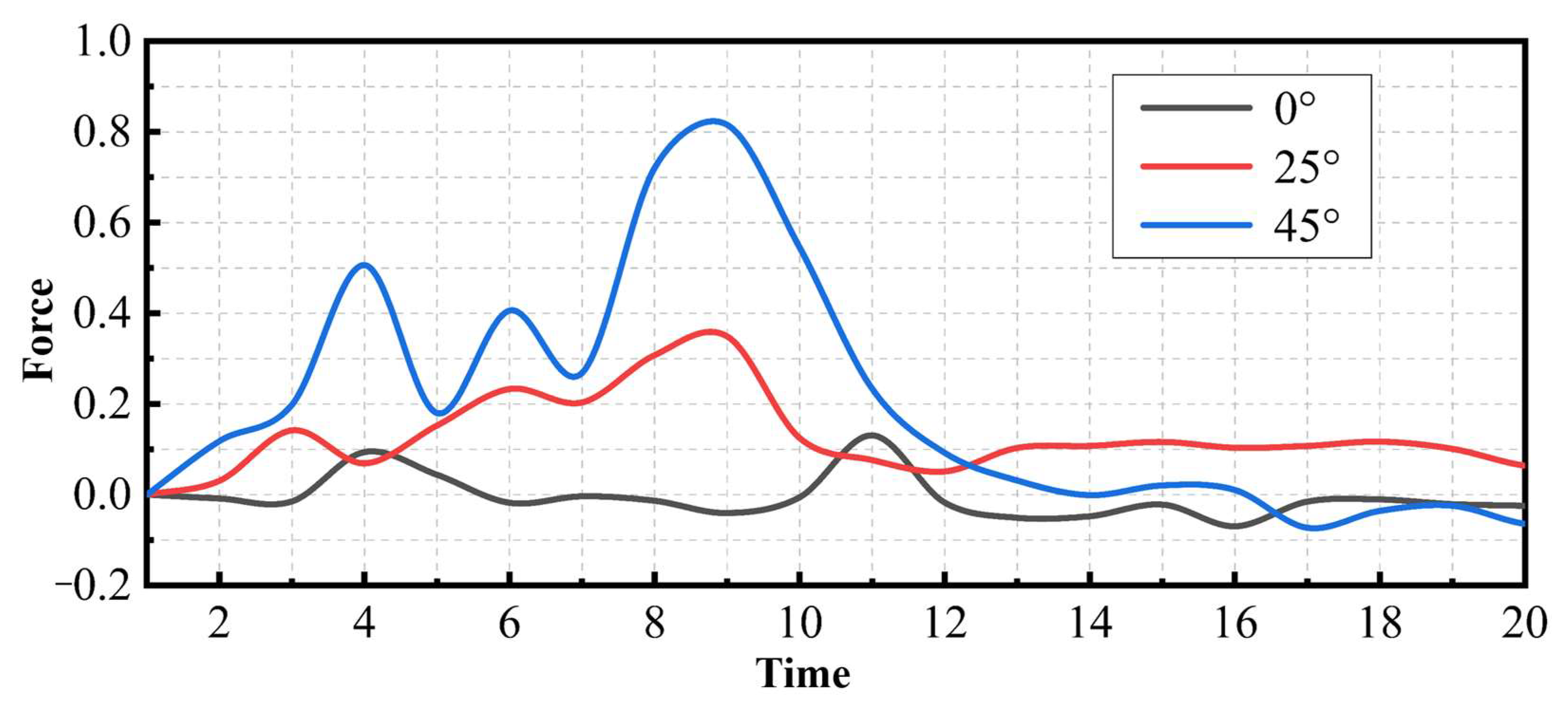
3.1.2. Characteristics of Lateral Force
3.2. Processed Surface Topography
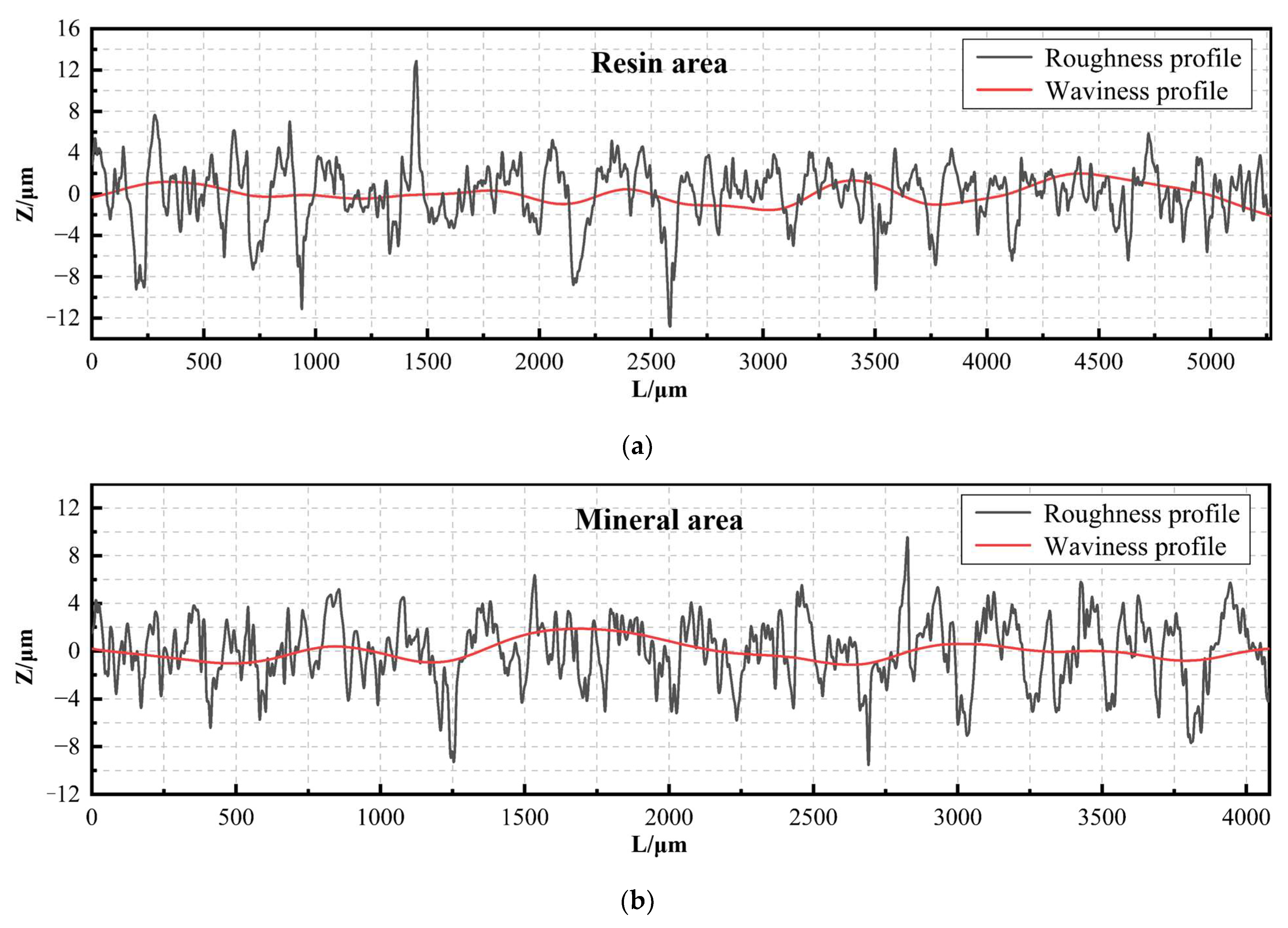
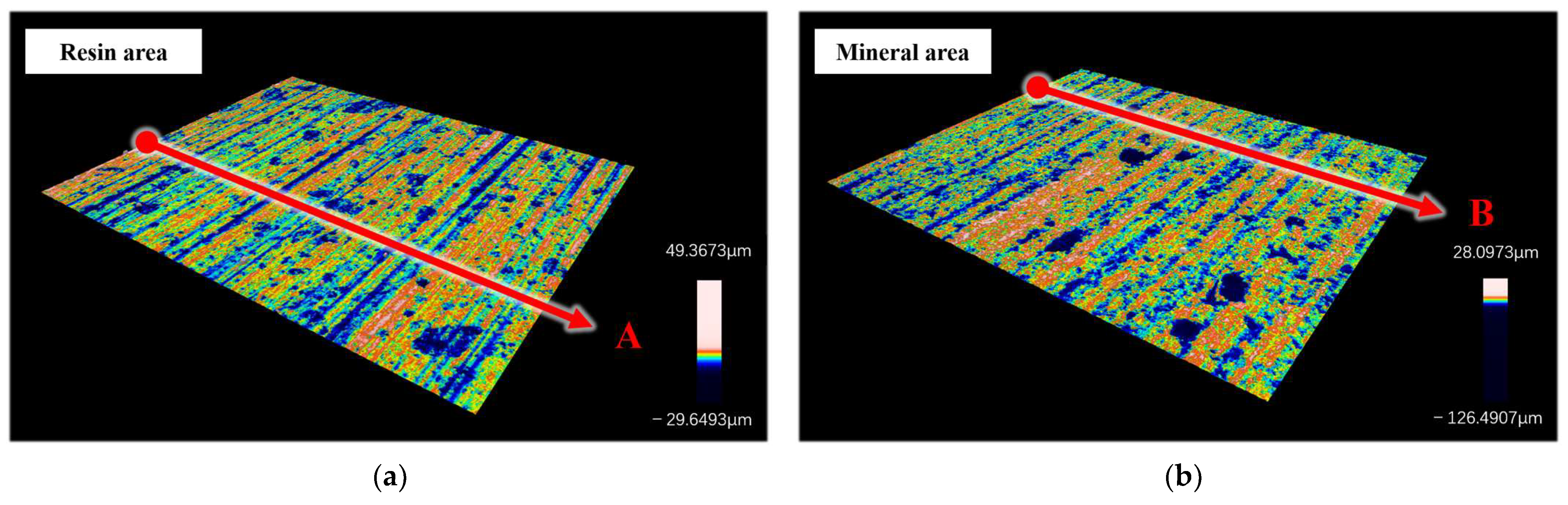
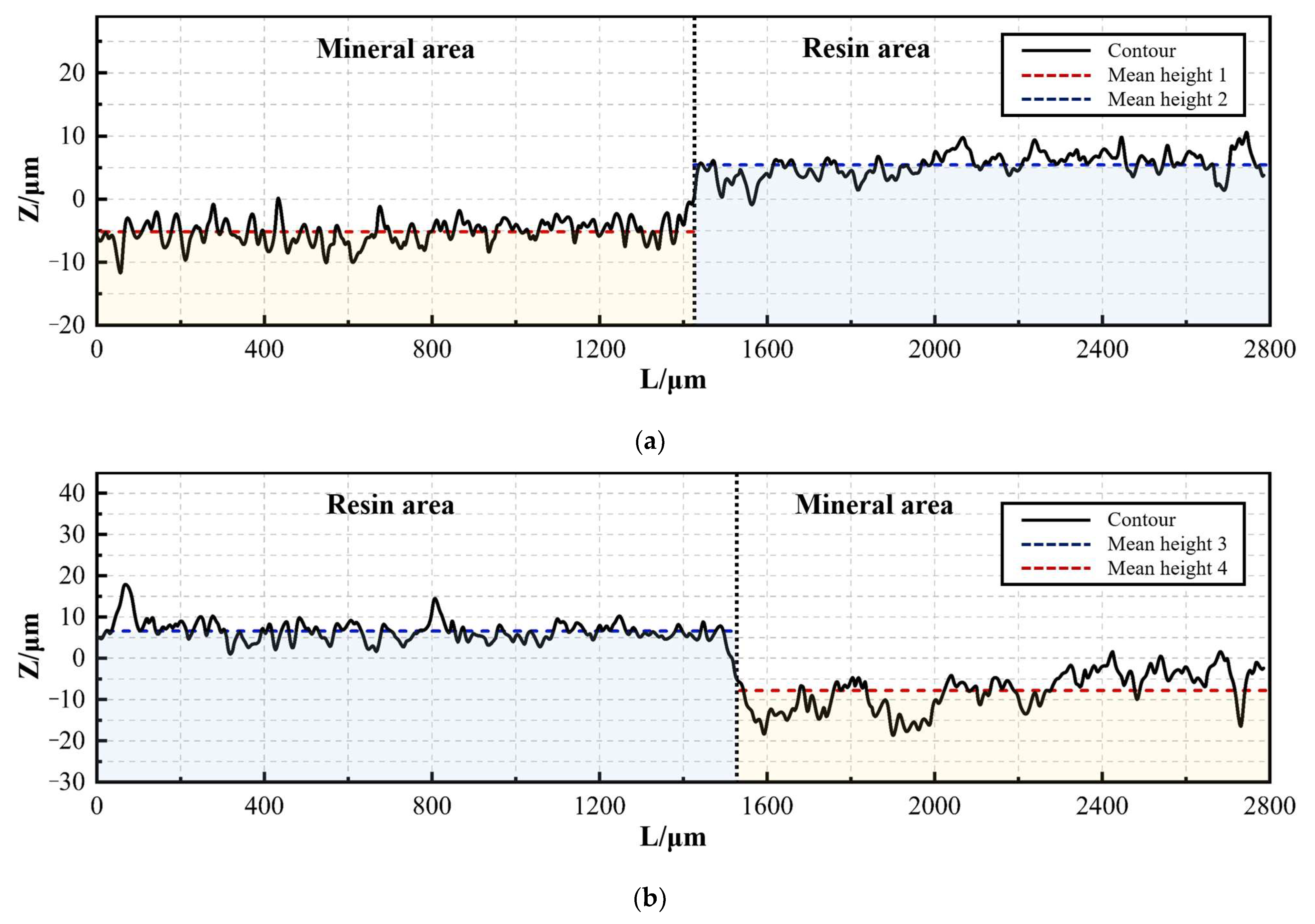
3.2.1. Surface Topography of a Single Material Type Area
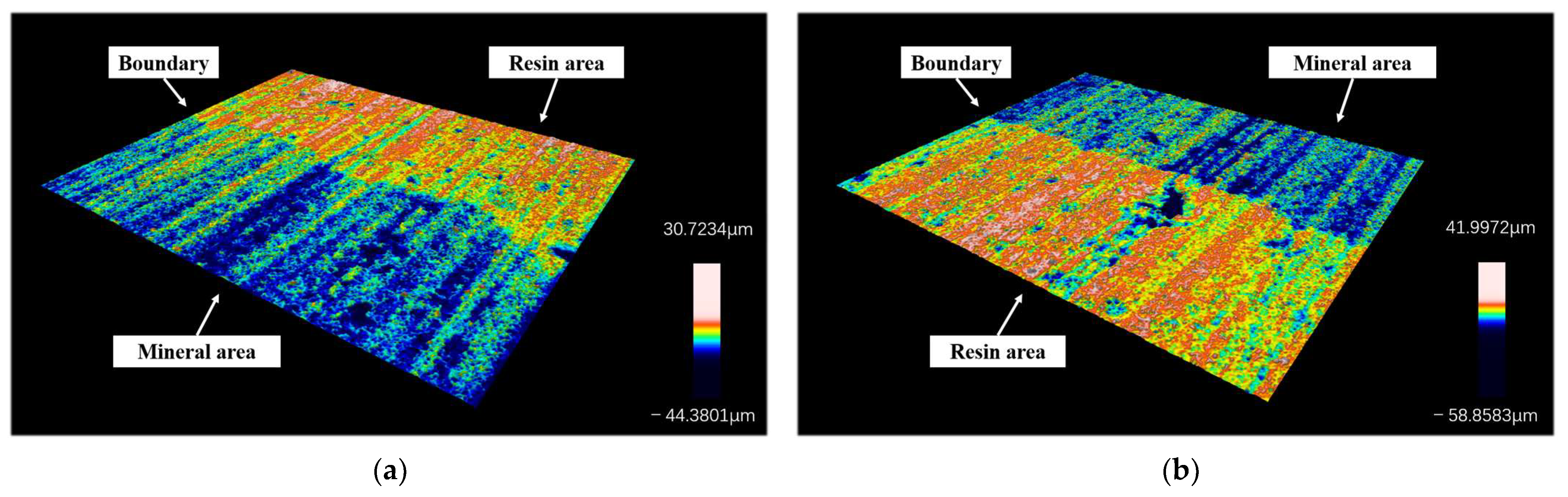
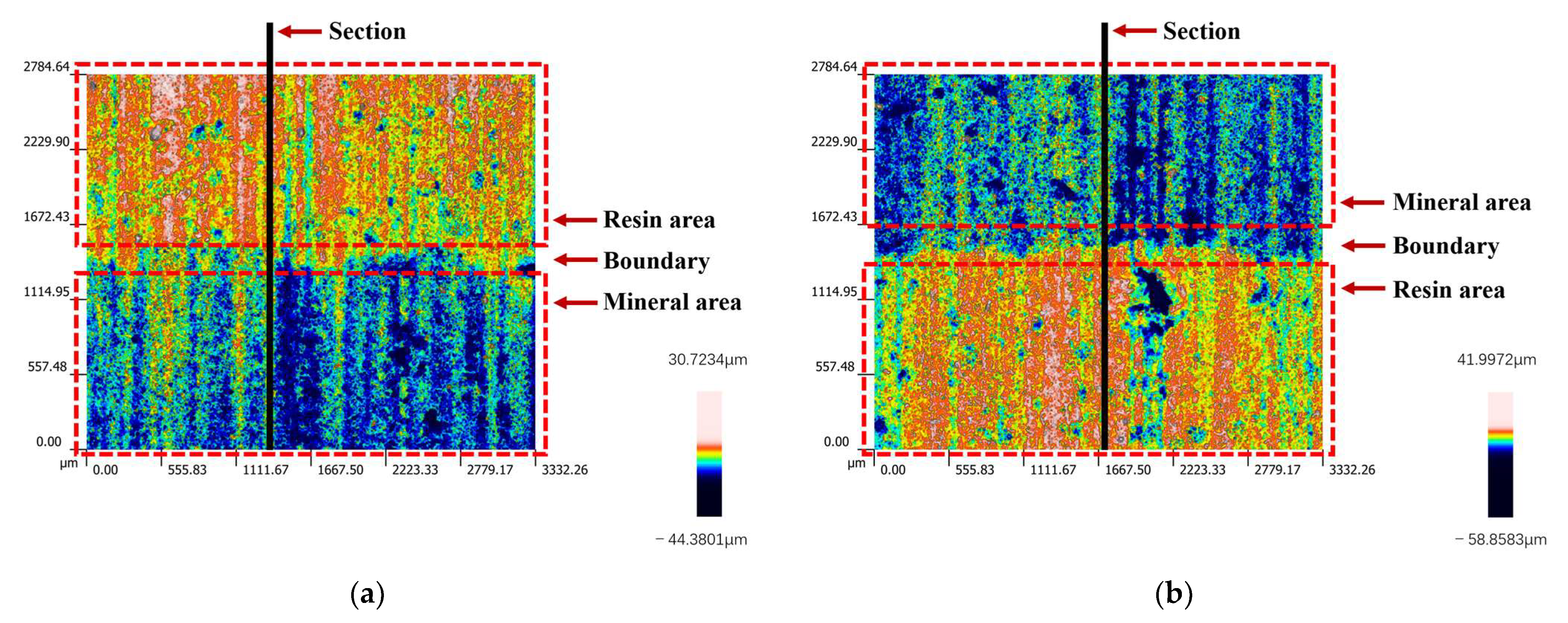
3.2.2. Surface Morphology of Resin–Mineral Interface
4. Discussion
5. Conclusions
Author Contributions
Funding
Institutional Review Board Statement
Informed Consent Statement
Data Availability Statement
Conflicts of Interest
References
- Rakic, A.; Zivanovic, S.; Dimic, Z.; Knezevic, M. Digital Twin Control of Multi-Axis Wood CNC Machining Center Based on LinuxCNC. Bioresources 2021, 16, 1115–1130. [Google Scholar] [CrossRef]
- Svoboda, O.; Bach, P.; Liotto, G.; Wang, C. Definitions and correlations of 3D volumetric positioning errors of CNC machining centers. In Proceedings of the IMTS 2004 Manufacturing Conference, Chicago, IL, USA, 8–10 September 2004. [Google Scholar]
- Yemelyanov, N.V.; Yemelyanova, I.V.; Zubenko, V.L. Improving machining accuracy of cnc machines with innovative design methods. IOP Conf. Ser. Mater. Sci. Eng. 2018, 327, 042028. [Google Scholar] [CrossRef]
- Guo, C.; Zhu, L.; Li, W.; Li, Y. Research on Mixed Fiber Reinforced Resin Mineral Composites. Eng. Plast. Appl. 2016, 44, 62–67. [Google Scholar]
- Ajami, A.; Bahari, M.; Hassanpour-Kashani, A.; Abed-Kahnamoui, M.; Savadi-Oskoee, A.; Azadi-Oskoee, F. Shear bond strengths of composite resin and giomer to mineral trioxide aggregate at different time intervals. J. Clin. Exp. Dent. 2017, 9, e906–e911. [Google Scholar] [CrossRef] [PubMed]
- Yan, K.; Zuo, J.; Hong, Y. Study on Dynamic Characteristics of Resin mineral Composite Grinding Machine Bed. Equip. Manuf. Technol. 2017, 10, 210–213. [Google Scholar]
- Zhang, C.; Zhang, J.; Ren, X.; Zhang, J. Mechanical Properties of Mo Fiber-reinforced Resin Mineral Composites with Different Mass Ratio of Resin and Hardener. J. Wuhan Univ. Technol. 2019, 34, 383–390. [Google Scholar] [CrossRef]
- Aneli, J.; Shamanuri, L.; Bakradze, N. Improvement of the Properties of Polymer Composites by Mineral Basalt Modified with Tetraethoxysilane. In Advances in Manufacturing Processes, Intelligent Methods and Systems in Production Engineering; Springer: Cham, Switzerland, 2022. [Google Scholar] [CrossRef]
- Huang, Z.; Zhang, Y.; Jiang, Y. Comparison on forming quality and static strength for self-piercing riveting joints of laminated plates with different sandwich materials and AA5052 aluminum alloy. Forg. Stamp. Technol. 2022, 47, 87–94. [Google Scholar] [CrossRef]
- Qi, Z.; Ge, E.; Yang, J.; Li, F.; Jin, S. Influence mechanism of multi-factor on the diameter of the stepped hole in the drilling of CFRP/Ti stacks. Int. J. Adv. Manuf. Technol. 2021, 113, 923–933. [Google Scholar] [CrossRef]
- Sasahara, H.; Sukegawa, Y.; Yamada, Y. CFRP machining capability by a circular saw. Precis. Eng. 2018, 52, 291–299. [Google Scholar] [CrossRef]
- Upadhyaya, R.V.; Suntharavadivel, T.G. Bonding behaviour of epoxy resin over mineral composite in FRP retrofit. Int. J. Civ. Eng. Technol. 2018, 9, 362–371. [Google Scholar]
- Radhakrishnan, S.; Rao, A.; Shenoy, R.; BS, S. Comparative Evaluation of Tensile Bond Strength and Shear Bond Strength of Mineral Trioxide Aggregate with Composite Resin and Resin Modified Glass Ionomer. Indian J. Public Health Res. Dev. 2019, 10, 156. [Google Scholar] [CrossRef]
- Khalimonenko, A.D.; Pompeev, K.P.; Timofeev, T.Y. Method of calculating intermediate diametral sizes and allowances for designing technology of manufacture of details. In Proceedings of the International Conference on Actual Issues of Mechanical Engineering, Tomsk, Russia, 27–29 July 2017. [Google Scholar] [CrossRef]
- Hu, X.; Sun, W. Designs for electrical control system of diamond band saw cutting machine. Diam. Abras. Eng. 2015, 35, 71–75. [Google Scholar]
- Qing, J.; Lin, F.; Peng, S.; Xiao, L.; Chen, C.; Zhang, L.; Pan, X. Study of the Uniformity of Ultra-Thin Diamond Band Saw Plating. Superhard Mater. Eng. 2016, 28, 5–8. [Google Scholar]
- Van Der, P.E. Band Saw with Diamond Abrasive Teeth. U.S. Patent 2,442,153A, 18 March 2024. [Google Scholar]
- Kang, J.; Zhang, J.; Duan, Z.; Zhang, H. Modeling for prediction of sawing force based on the maximum undeformed chip distribution in the granite sawing. Int. J. Adv. Manuf. Technol. 2023, 124, 111–126. [Google Scholar] [CrossRef]
- Lin, Y.; Yang, G.; Huang, X. Thin-layer Micro-element Method for Cohesive Soil Passive Earth Pressure Determination on Retaining Walls. J. Highw. Transp. Res. Dev. 2012, 6, 24–31. [Google Scholar] [CrossRef]
- Jung, J.H.; Na, Y.S.; Cho, K.M.; Dimiduk, D.M.; Choi, Y.S. Microcompression Behaviors of Single Crystals Simulated by Crystal Plasticity Finite Element Method. Metall. Mater. Trans. A Phys. Metall. Mater. Sci. 2015, 46, 4834–4840. [Google Scholar] [CrossRef]
- Zhu, Z.; Gao, Y. Study on surface roughness and morphology of diamond wire as-sawn sapphire crystal wafers. Int. J. Adv. Manuf. Technol. 2023, 125, 2077–2090. [Google Scholar] [CrossRef]
- Gupta, A.; Chen, C.C.A.; Hsu, H.W. Study on diamond wire wear, surface quality, and subsurface damage during multi-wire slicing of c-plane sapphire wafer. Int. J. Adv. Manuf. Technol. 2019, 100, 1801–1814. [Google Scholar] [CrossRef]
- ISO 21920-1:2022; Geometrical Product Specifications—Surface Texture: Profile. ISO: Berlin, Germany, 2022.
- Yang, H.; Feng, P.; Zhang, J.; Zhang, X.; Wang, J. Toward understanding the mechanism in ultrasonic cutting of silica aerogel composites using a bionic micro-serrated tool. J. Manuf. Process. 2023, 101, 480–500. [Google Scholar] [CrossRef]
- Wang, K.; Zhang, J.; Kang, J.; Zhang, H. Analysis of diamond wear morphology and segment wear evolution during the process of hard granite sawing. Int. J. Refract. Met. Hard Mater. 2023, 110, 106040. [Google Scholar] [CrossRef]
- Seeholzer, L.; Süssmaier, S.; Kneubühler, F.; Wegener, K. Experimental investigation of the machining characteristics in diamond wire sawing of unidirectional CFRP. Int. J. Adv. Manuf. Technol. 2021, 117, 2197–2212. [Google Scholar] [CrossRef] [PubMed]
- Zhang, Y.; Zhang, J.; Zheng, Y. The thermal expansion behaviour of carbon fiber-reinforced resin mineral composite postcured under various temperatures. J. Reinf. Plast. Compos. 2016, 36, 505–518. [Google Scholar] [CrossRef]
- Yin, J.; Zhang, J.; Zhang, Y.; Li, G. Influence of Aggregate Moisture Content on the Mechanical Properties of Resin Mineral Composite. In Proceedings of the International Conference on Chemical, Material and Food Engineering, Kunming, China, 25–26 July 2015. [Google Scholar] [CrossRef]
- Krilek, J.; Kuvik, T.; Kováč, J.; Melicherčík, J. Research on the Side Deflection of the Saw Band of a Joinery Band Saw Influenced by the Selected Technical and Technological Factors. Manag. Syst. Prod. Eng. 2020, 28, 148–153. [Google Scholar] [CrossRef]
- Mikaeil, R.; Ozcelik, Y.; Ataei, M.; Shaffiee Haghshenas, S. Application of harmony search algorithm to evaluate performance of diamond wire saw. J. Min. Environ. 2019, 10, 27–36. [Google Scholar] [CrossRef]
- Gao, J.G.; Jiang, Z.F.; Shen, D.J. Different Working Parameters of Biomass Processing with the Band Saw out, the Impact of Vibration Frequency and the Rate of Tooth. In Proceedings of the 3rd Annual International Conference on Advanced Material Engineering (AME 2017), Shanghai, China, 14–16 April 2017. [Google Scholar] [CrossRef]
- Gisario, A.; Kazarian, M.; Martina, F.; Mehrpouya, M. Metal additive manufacturing in the commercial aviation industry: A review. J. Manuf. Syst. 2019, 53, 124–149. [Google Scholar] [CrossRef]
- Kirmani, M.H.; Ramachandran, J.; Arias-Monje, P.J.; Gulgunje, P.; Kumar, S. The effects of processing and carbon nanotube type on the impact strength of aerospace-grade bismaleimide based nanocomposites. Polym. Eng. Sci. 2022, 62, 1187–1196. [Google Scholar] [CrossRef]
- Das, S.; Pandivelan, C. Grinding characteristics during ultrasonic vibration assisted grinding of alumina ceramic in selected dry and MQL conditions. Mater. Res. Express 2020, 7, 085404. [Google Scholar] [CrossRef]
- Chaudhari, A.; Yusufzai, M.Z.K.; Vashista, M. Grindability study of hard to cut AISI D2 steel upon ultrasonic vibration-assisted dry grinding. Proc. Inst. Mech. Eng. Part E J. Process Mech. Eng. 2022, 236, 915–925. [Google Scholar] [CrossRef]
- Alzraikat, H.; Taha, N.A.; Qasrawi, D.; Burrow, M.F. Shear bond strength of a novel light cured calcium silicate based-cement to resin composite using different adhesive systems. Dent. Mater. J. 2016, 35, 881–887. [Google Scholar] [CrossRef]
- Atilla, D.; Kiral, B.G. Dynamic mechanical behavior of composite materials reinforced by graphene and huntite minerals. Mater. Test. 2021, 63, 1090–1096. [Google Scholar] [CrossRef]


| Aggregate Type | Compressive Strength (MPa) | Flexure Strength (MPa) | Density (g/cm3) |
|---|---|---|---|
| Jinan blue granite | 202.43 | 29.04 | 3.071 |
| Quartz stone | 141.52 | 22.85 | 2.674 |
| Processing Condition No. | 1-1 | 1-2 | 1-3 | 2-1 | 2-2 | 2-3 | 3-1 | 3-2 | 3-3 | 4-1 | 4-2 | 4-3 |
|---|---|---|---|---|---|---|---|---|---|---|---|---|
| Sawing speed (m/min) | 1600 | 1600 | 1600 | 1440 | 1440 | 1440 | 1280 | 1280 | 1280 | 1120 | 1120 | 1120 |
| Feed speed (mm/min) | 4 | 6 | 8 | 4 | 6 | 8 | 4 | 6 | 8 | 4 | 6 | 8 |
| Tangential force (N) | 1.12 | 1.20 | 1.28 | 1.23 | 1.30 | 1.52 | 1.30 | 1.41 | 1.49 | 1.58 | 1.59 | 1.67 |
| Feed force (N) | 3.61 | 4.34 | 4.38 | 4.01 | 4.36 | 4.76 | 4.18 | 4.62 | 5.15 | 4.38 | 4.97 | 5.45 |
| Processing Condition No. | 1-1 | 1-2 | 1-3 | 2-1 | 2-2 | 2-3 | 3-1 | 3-2 | 3-3 | 4-1 | 4-2 | 4-3 |
|---|---|---|---|---|---|---|---|---|---|---|---|---|
| Sawing speed (m/min) | 1600 | 1600 | 1600 | 1440 | 1440 | 1440 | 1280 | 1280 | 1280 | 1120 | 1120 | 1120 |
| Feed speed (mm/min) | 4 | 6 | 8 | 4 | 6 | 8 | 4 | 6 | 8 | 4 | 6 | 8 |
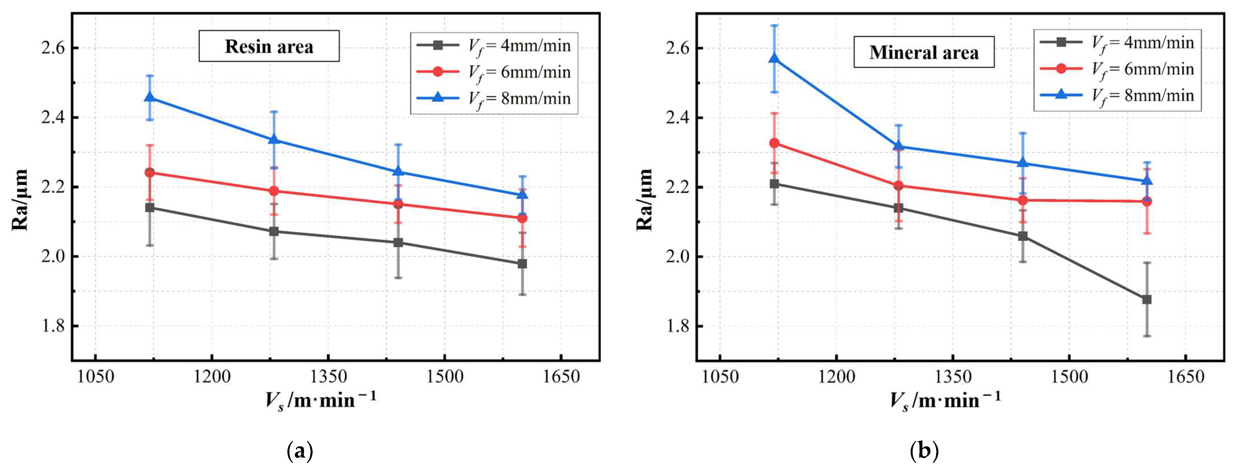
| Resin area roughness (Ra) | 1.979 | 2.110 | 2.176 | 2.040 | 2.150 | 2.243 | 2.072 | 2.188 | 2.334 | 2.140 | 2.241 | 2.456 |
| Mineral area roughness (Ra) | 1.877 | 2.159 | 2.217 | 2.059 | 2.162 | 2.268 | 2.140 | 2.204 | 2.317 | 2.209 | 2.326 | 2.568 |
| Processing Condition No. | 1-1 | 1-2 | 1-3 | 2-1 | 2-2 | 2-3 | 3-1 | 3-2 | 3-3 | 4-1 | 4-2 | 4-3 |
|---|---|---|---|---|---|---|---|---|---|---|---|---|
| Height difference (μm) | 11.70 | 13.47 | 12.17 | 11.54 | 12.05 | 14.84 | 10.26 | 12.64 | 13.74 | 13.07 | 12.22 | 13.19 |
Disclaimer/Publisher’s Note: The statements, opinions and data contained in all publications are solely those of the individual author(s) and contributor(s) and not of MDPI and/or the editor(s). MDPI and/or the editor(s) disclaim responsibility for any injury to people or property resulting from any ideas, methods, instructions or products referred to in the content. |
© 2024 by the authors. Licensee MDPI, Basel, Switzerland. This article is an open access article distributed under the terms and conditions of the Creative Commons Attribution (CC BY) license (https://creativecommons.org/licenses/by/4.0/).
Share and Cite
Sun, J.; Zhang, J.; Gu, W.; Long, Y.; Guo, C. Experimental Investigation on Diamond Band Saw Processing of Resin Mineral Composites. Materials 2024, 17, 1814. https://doi.org/10.3390/ma17081814
Sun J, Zhang J, Gu W, Long Y, Guo C. Experimental Investigation on Diamond Band Saw Processing of Resin Mineral Composites. Materials. 2024; 17(8):1814. https://doi.org/10.3390/ma17081814
Chicago/Turabian StyleSun, Jiahao, Jianhua Zhang, Weizhou Gu, Yunfang Long, and Chuanxin Guo. 2024. "Experimental Investigation on Diamond Band Saw Processing of Resin Mineral Composites" Materials 17, no. 8: 1814. https://doi.org/10.3390/ma17081814
APA StyleSun, J., Zhang, J., Gu, W., Long, Y., & Guo, C. (2024). Experimental Investigation on Diamond Band Saw Processing of Resin Mineral Composites. Materials, 17(8), 1814. https://doi.org/10.3390/ma17081814