

Study on Molten Pool Flow and Porosity Defects in Laser–Tungsten Inert Gas (TIG) Welding of 4J36 Invar Steel


Abstract

1. Introduction
2. Materials and Methods
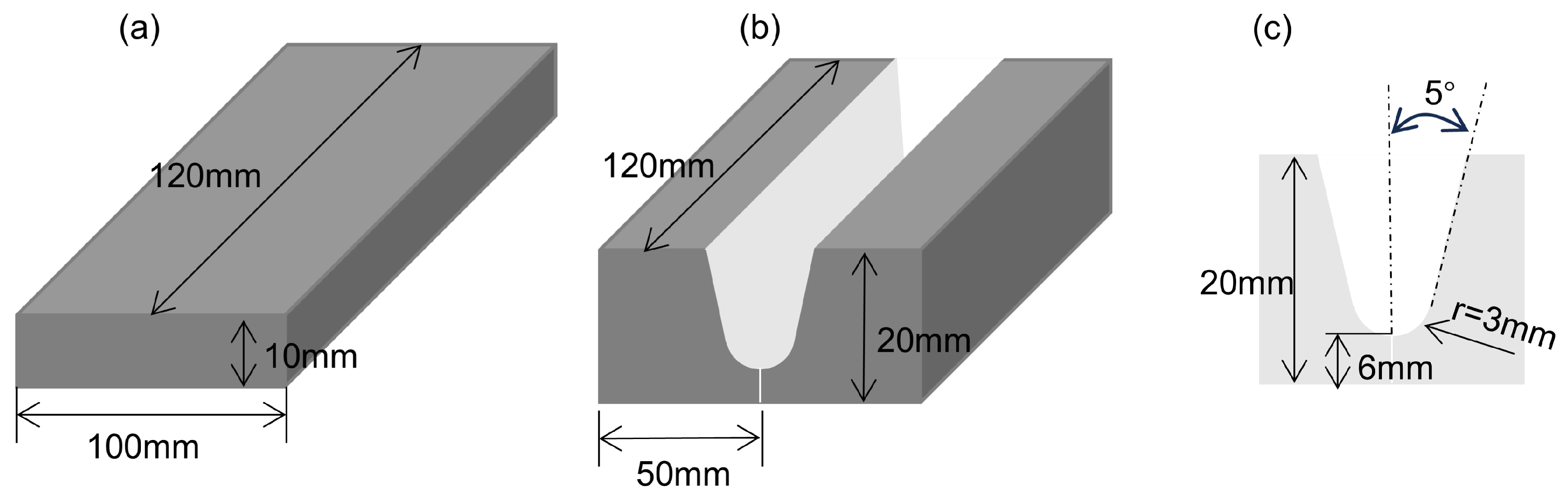
2.1. Materials
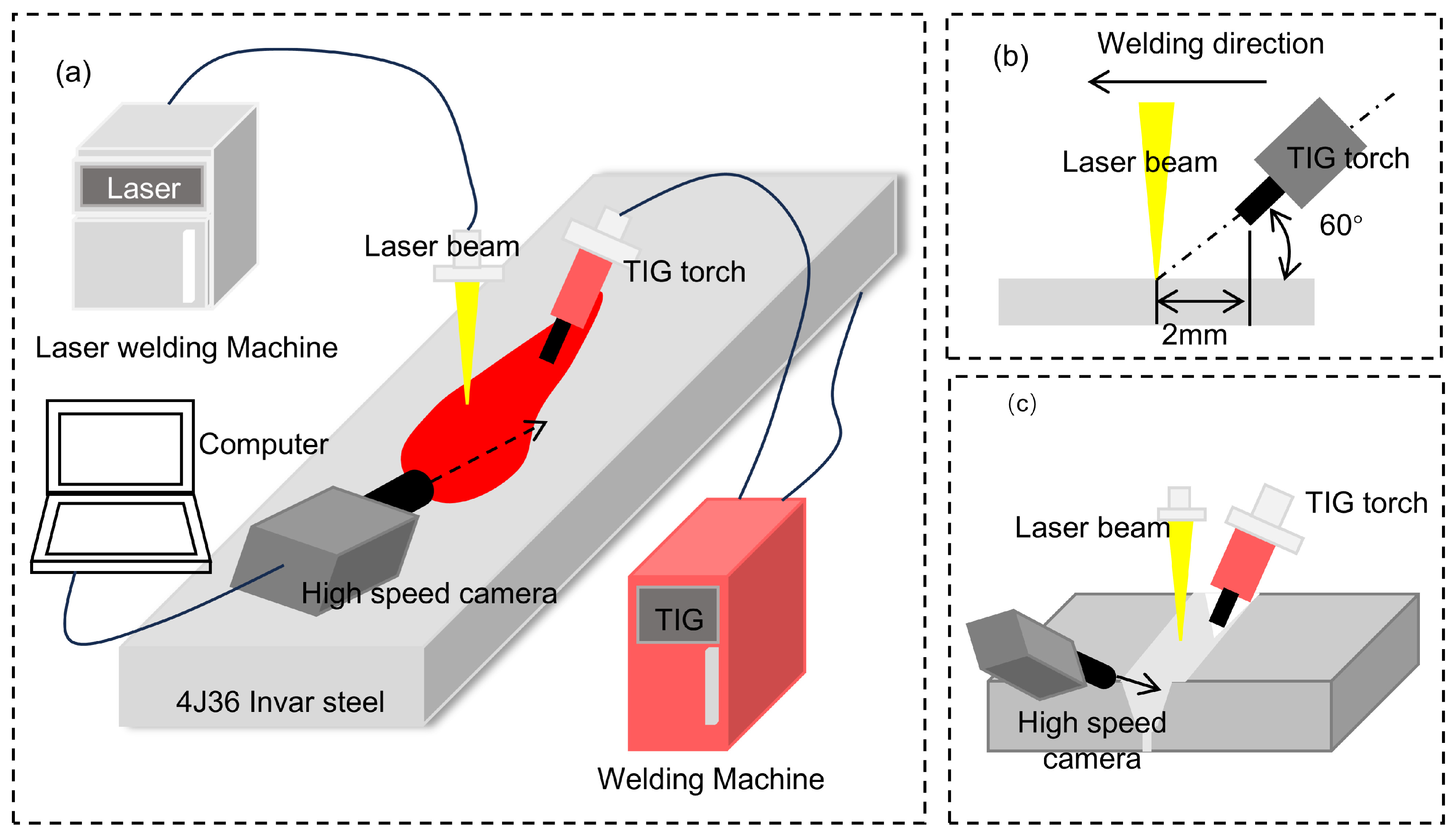
2.2. Methods
2.3. Molten Pool Numerical Simulation Analysis
2.3.1. Basic Assumptions
- (1)
- The liquid metal in the computational domain is an incompressible Newtonian fluid in laminar flow.
- (2)
- The influence of shielding gas and metal transfer is neglected during the welding process.
- (3)
- The driving forces in the molten pool mainly include the recoil pressure, surface tension, buoyancy, gravity, arc pressure, and electromagnetic force.
2.3.2. Control Equations
- (1)
- The mass conservation equation is
- (2)
- The conservation of momentum equation is
- (1)
- The conservation of energy equation is
2.3.3. Boundary Condition
- (1)
- Initial conditions are
- (2)
- Boundary conditions
2.3.4. Model Setup
2.3.5. Material Properties
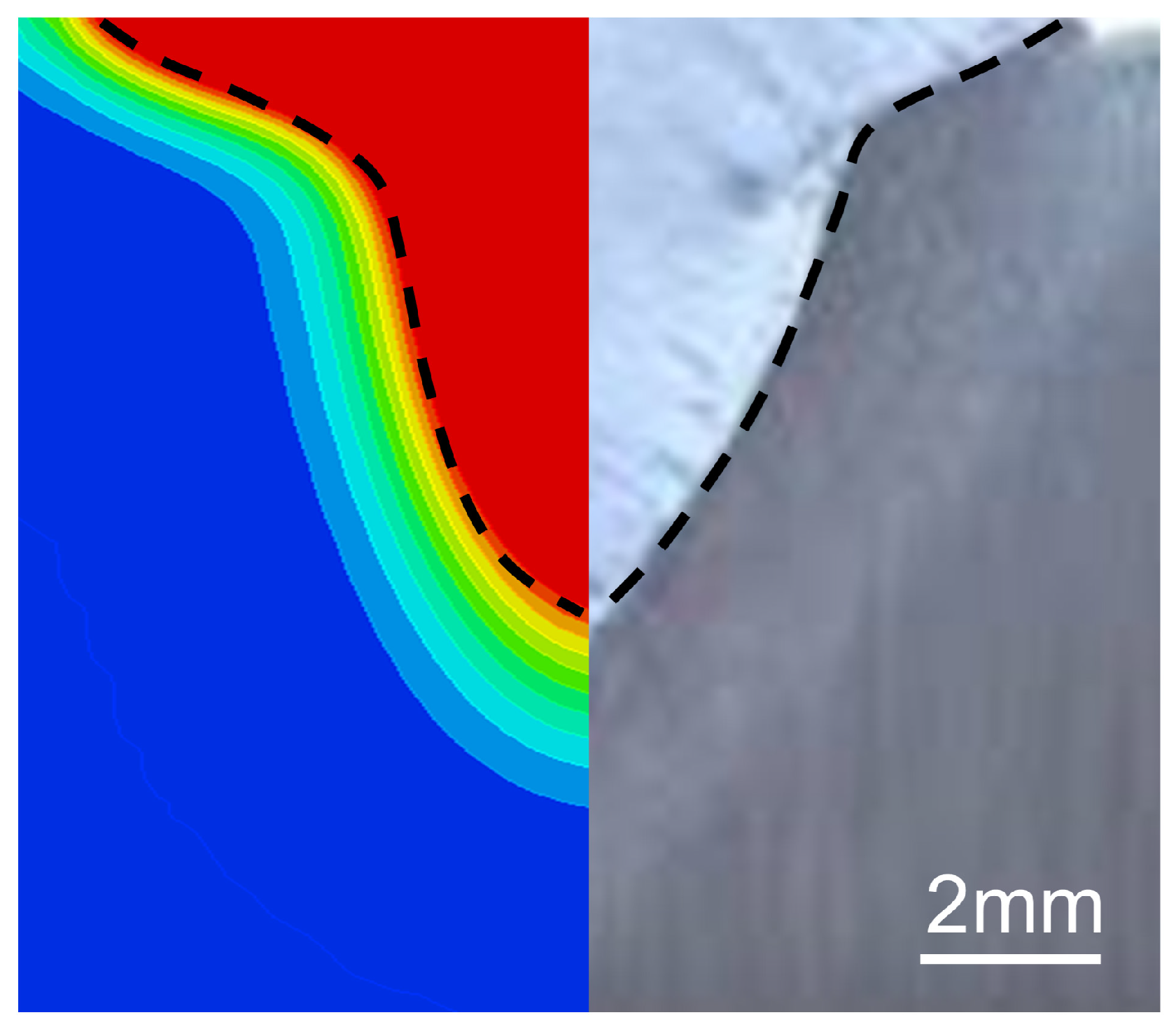
2.3.6. Model Validation
3. Results
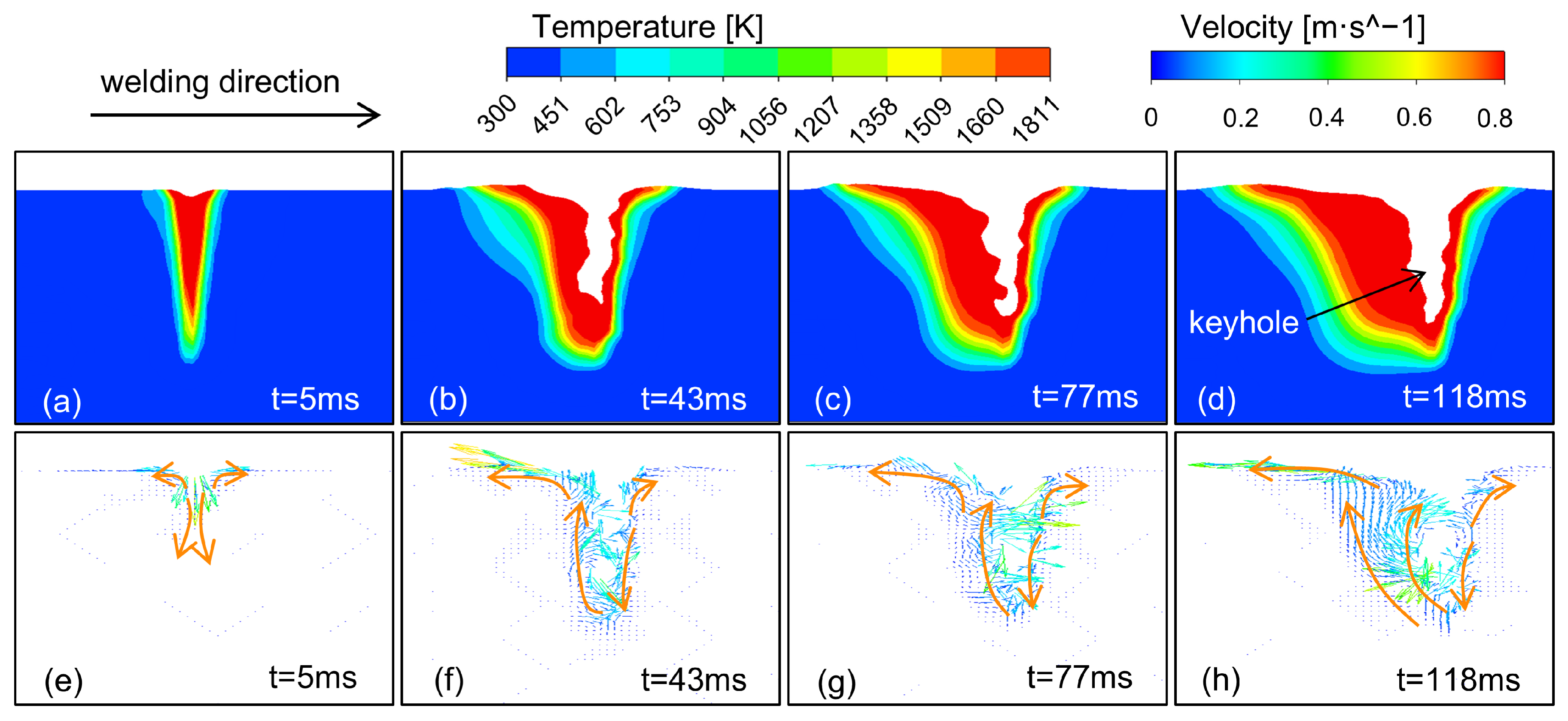
3.1. Flow Behavior of Molten Pool
3.2. Mechanism of Porosity Formation
3.2.1. Influence of the Molten Pool Dynamics Behavior
3.2.2. The Influence of 4J36 Invar Steel Material Properties
3.2.3. Influence of Welding Process Parameters
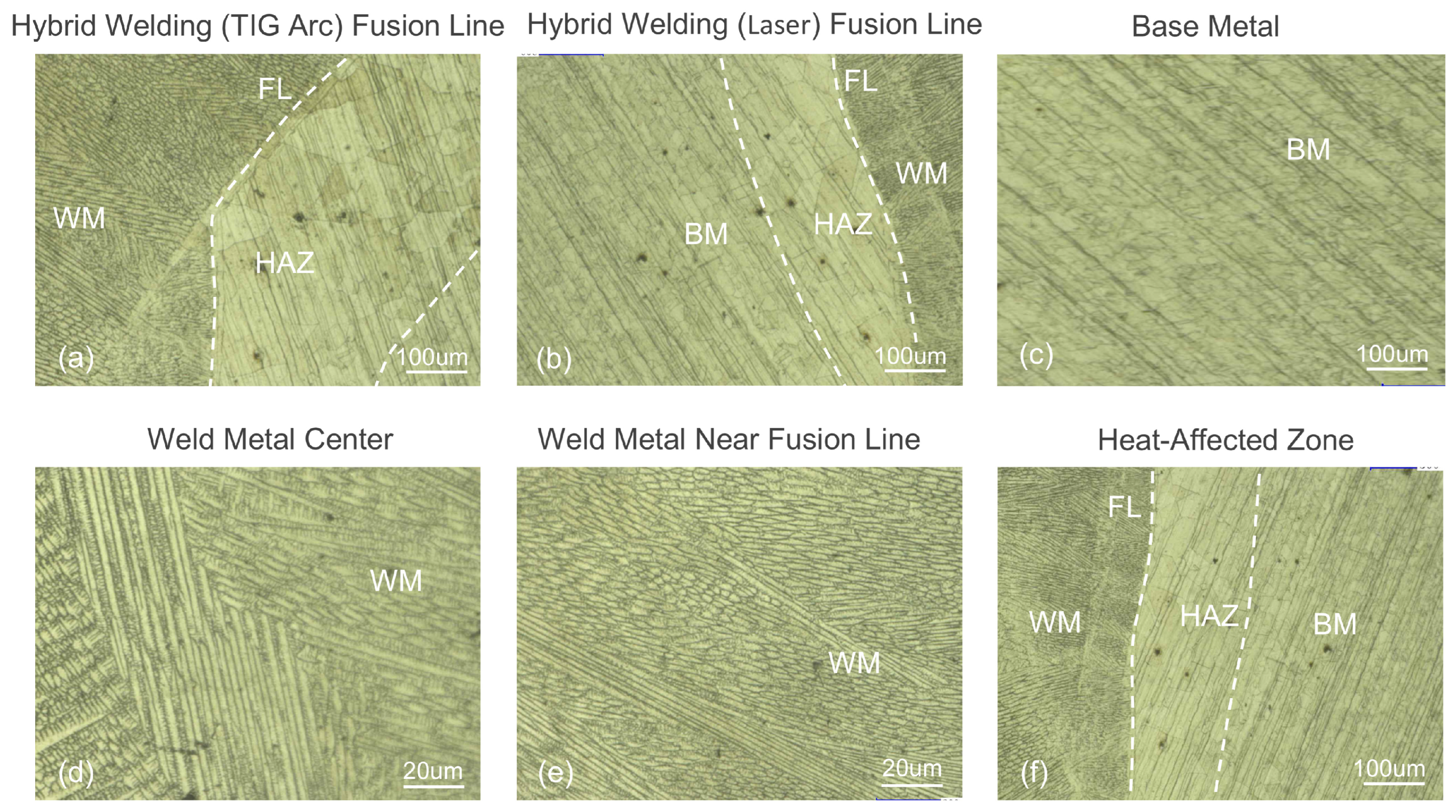
3.3. Microstructure Analysis of Invar Steel Laser–TIG Hybrid Welded Joint
3.4. Porosity Inhibition Measures
- (1)
- The base metal must be thoroughly cleaned prior to welding. Surface oil, grease, and other contaminants are first removed with organic solvents such as acetone, alcohol, and others. Then, the surface oxides are removed by sanding with a stainless steel wire brush or sandpaper. Finally, the surface is thoroughly cleaned again of oil, grease, dust, or other organic contaminants with organic solvents such as acetone, alcohol, and others. The base metal surface must be maintained in a completely dry condition prior to welding to prevent moisture retention. The cooling rate of the molten pool can be effectively reduced through preheating treatment of the base metal.
- (2)
- When the laser power is increased from 4 kW to 8 kW, the enhanced heat input significantly increases the penetration depth and enlarges the keyhole size. However, when the laser power exceeds 6 kW, it tends to induce keyhole instability. Therefore, maintaining the power within the 4–6 kW range is recommended. When the welding speed decreases from 3 m/min to 0.3 m/min, the prolonged thermal interaction promotes molten pool flow expansion. However, the welding speed exceeding 1.5 m/min increases porosity defects. Thus, an optimal speed range of 0.5–1.5 m/min is recommended. Increasing the welding current from 100 A to 200 A widens the keyhole and enhances molten pool fluidity. Furthermore, maintaining the current within the 150–200 A range effectively mitigates the risk of keyhole collapse. The coordinated optimization of multiple parameters enables a stabilized welding process.
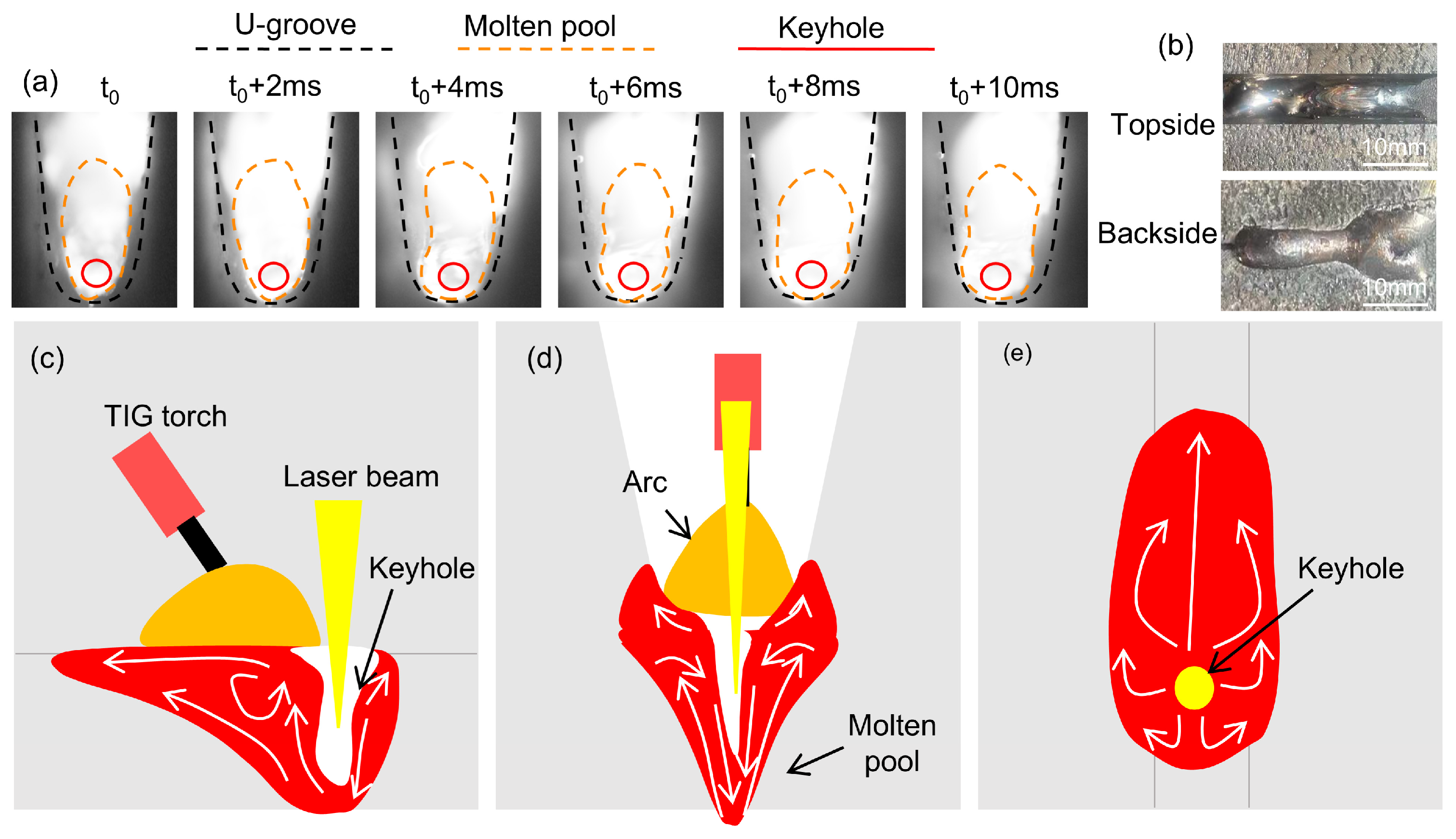
3.5. Flow Behavior of Molten Pool in U-Groove
3.6. Influence of Process Parameters on Flow Behavior of Molten Pool in U-Groove
4. Conclusions
- (1)
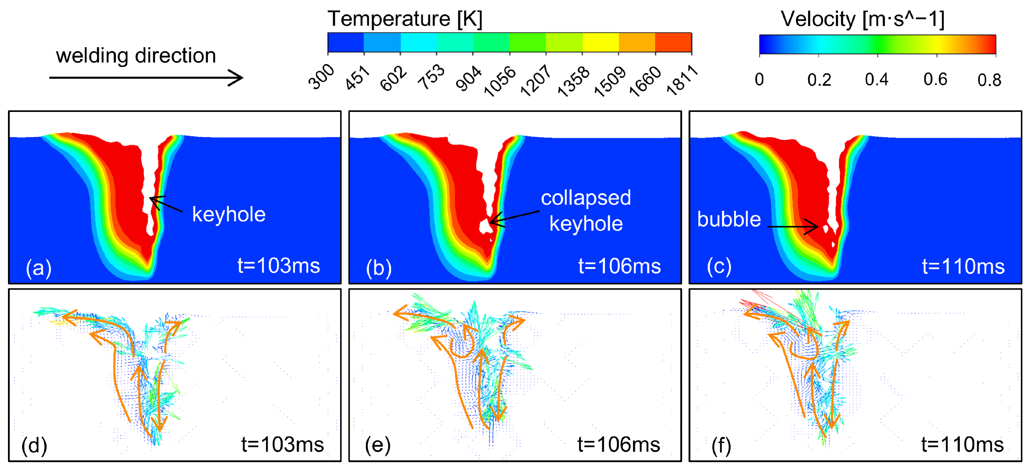
- The formation of porosity defects is primarily associated with the instability of the keyhole and the rapid solidification behavior of the molten pool. When the keyhole collapses under the action of surface tension, the gas inside is wrapped by the liquid metal, thus forming bubbles. While some bubbles escape upon the re-establishment of the keyhole, others remain trapped and migrate within the molten pool. Furthermore, the rapid solidification and high surface tension of the 4J36 Invar steel molten pool significantly impede bubble escape, ultimately forming porosity defects.
- (2)
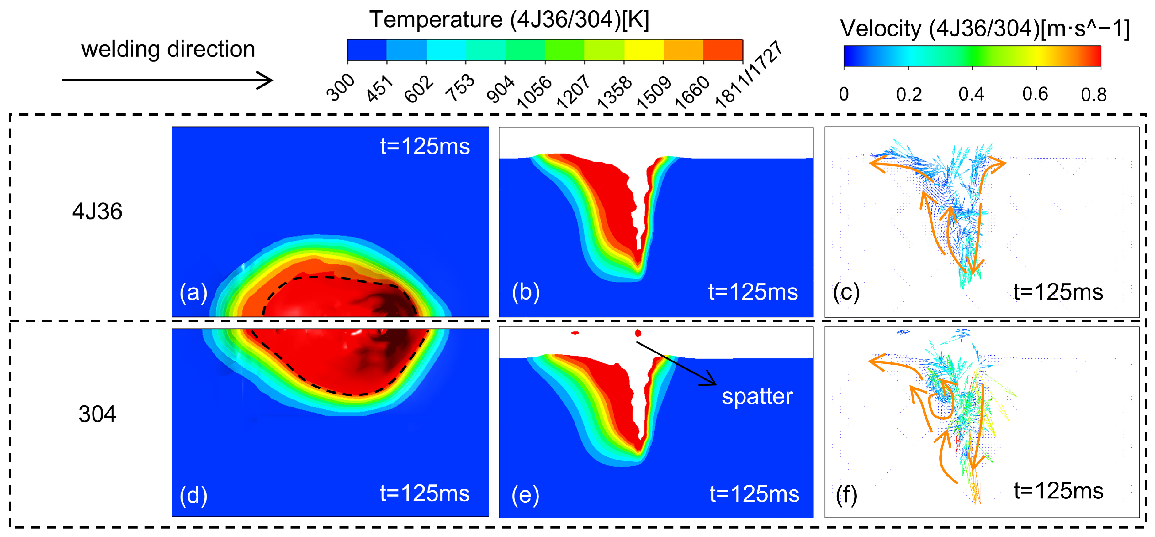
- The formation of porosity defects is influenced by the stability of the keyhole, the flow behavior of the molten pool, and the inherent properties of the material. Keyhole collapse is the cause of bubble generation. The flow of the molten pool is driven by recoil pressure, surface tension, and the Marangoni effect. Flow behavior influences the migration and escape of bubbles. Moreover, the fluidity of the molten pool of 4J36 Invar steel is poor, which further exacerbates the tendency of bubble retention and porosity formation. Due to its high tension and low fluidity, the 4J36 Invar steel molten pool exhibits a higher risk of porosity defects than 304 stainless steel.
- (3)
- When the laser power is increased from 4 kW to 8 kW, the enhanced heat input significantly increases the penetration depth and enlarges the keyhole size. However, when the laser power exceeds 6 kW, it tends to induce keyhole instability. When the welding speed decreases from 3 m/min to 0.3 m/min, the prolonged thermal interaction promotes molten pool flow expansion. However, the welding speed exceeding 1.5 m/min increases porosity defects. Increasing the welding current from 100 A to 200 A widens the keyhole and enhances molten pool fluidity.
- (4)
- The main measure to suppress porosity defects is the optimization of process parameters. To achieve a balance between molten pool fluidity and keyhole stability, the laser power, welding speed, and welding current are maintained at 4–6 kW, 0.5–1.0 m/min, and 150–170 A, respectively. The surface of the base material can also be cleaned to reduce the source of impurity gases, and the base material can be preheated to reduce the cooling rate of the molten pool.
Author Contributions
Funding
Institutional Review Board Statement
Informed Consent Statement
Data Availability Statement
Conflicts of Interest
References
- Li, Y.; Wang, F.; Liu, H.; Yang, L.; Zhang, P.; Wang, Y.; Li, H. Effect of surface roughness on the performances of laser-welded Invar 36 alloy joints. Opt. Laser Technol. 2023, 162, 109307. [Google Scholar] [CrossRef]
- Liu, H.; Liu, P.; Tian, Q.; Dong, Z.; Chen, Y.; Guo, X. Microstructure and Mechanical Properties of Fe-36Ni Alloy Prepared by a Two-Step Hydrogen Reduction Process. JOM 2023, 76, 969–975. [Google Scholar] [CrossRef]
- Nayak, K.C.; Choi, H.; Lee, K.-B. Thermal expansion behavior of nitrogen-processed Al6061/SiC composites. J. Mater. Sci. 2024, 59, 18473–18487. [Google Scholar] [CrossRef]
- Zheng, S.; Sokoluk, M.; Yao, G.; de Rosa, I.; Li, X. Fe–Ni Invar alloy reinforced by WC nanoparticles with high strength and low thermal expansion. SN Appl. Sci. 2019, 1, 172. [Google Scholar] [CrossRef]
- Zhu, S.; Niu, B.; Chang, Z.; Long, B.; Yin, F.; Ouyang, L.; Xie, L.; Jiang, Z. Analysis of the thermal expansion and mechanical properties of laser cladding of Invar alloy. Int. J. Adv. Manuf. Technol. 2024, 132, 245–264. [Google Scholar] [CrossRef]
- Aldalur, E.; Suárez, A.; Veiga, F. Thermal expansion behaviour of Invar 36 alloy parts fabricated by wire-arc additive manufacturing. J. Mater. Res. Technol. 2022, 19, 3634–3645. [Google Scholar] [CrossRef]
- Huang, G.; He, G.; Gong, X.; He, Y.; Liu, Y.; Huang, K. Additive manufacturing of Invar 36 alloy. J. Mater. Res. Technol. 2024, 30, 1241–1268. [Google Scholar] [CrossRef]
- Sharma, R.; Mishra, A.; Nath, A.; Sarkar, S. Progress in Metallurgical and Mechanical Aspects of Complex Alloying and Composite Systems in Metal Additive Manufacturing. Trans. Indian Natl. Acad. Eng. 2024, 9, 269–291. [Google Scholar] [CrossRef]
- Sood, A.; Schimmel, J.; Ferreira, V.M.; Bosman, M.; Goulas, C.; Popovich, V.; Hermans, M.J.M. Directed energy deposition of Invar 36 alloy using cold wire pulsed gas tungsten arc welding: Effect of heat input on the microstructure and functional behaviour. J. Mater. Res. Technol. 2023, 25, 6183–6197. [Google Scholar] [CrossRef]
- Huang, G.; He, G.; Peng, X.; He, Y.; Chen, H.; Huang, K.; Liu, Y. Effect of processing parameters on the microstructure, mechanical properties and thermal expansion behavior of Invar 36 alloy manufactured by laser powder bed fusion. Mater. Sci. Eng. A 2024, 897, 146329. [Google Scholar] [CrossRef]
- Su, Y.; Yang, X.; Wu, D.; Meng, T.; Li, W.; Feng, W.; Vairis, A. Optimizing welding sequence of TIG cross-joint of Invar steel using residual stresses and deformations. J. Manuf. Process. 2023, 105, 232–245. [Google Scholar] [CrossRef]
- Zhou, Y.; Cheng, L.; Li, Y.; Wang, J.; Zhan, X. Interfacial microstructure evolution and mechanical properties in laser welded Invar alloy/TC4 dissimilar joints. Intermetallics 2024, 166, 108171. [Google Scholar] [CrossRef]
- Gao, Q.; Yan, T.; Ling, W.; Bu, H.; Zhan, X.; Shen, H. Effect of vapor/plasma-liquid flow behavior on the keyhole oscillation in laser-MIG hybrid welding of Invar alloy. Opt. Laser Technol. 2021, 140, 107054. [Google Scholar] [CrossRef]
- Gouzman, I.; Grossman, E.; Verker, R.; Atar, N.; Bolker, A.; Eliaz, N. Advances in Polyimide-Based Materials for Space Applications. Adv. Mater. 2019, 31, 1807738. [Google Scholar] [CrossRef]
- Yan, T.; Zhan, X.; Gao, Q.; Wang, F.; Ling, W. Influence of laser power on molten pool flow field of laser-MIG hybrid welded Invar alloy. Opt. Laser Technol. 2021, 133, 106539. [Google Scholar] [CrossRef]
- Liu, L.; Yang, H.; Tao, X.; Cheng, Z. Study on the coupling characteristics of laser-TIG hybrid heat source with different offsets. Int. J. Adv. Manuf. Technol. 2024, 134, 2337–2351. [Google Scholar] [CrossRef]
- Obidigbo, C.; Tatman, E.-P.; Gockel, J. Processing parameter and transient effects on melt pool geometry in additive manufacturing of Invar 36. Int. J. Adv. Manuf. Technol. 2019, 104, 3139–3146. [Google Scholar] [CrossRef]
- Zhu, B.; Zhao, Z.; Zou, J.; Wang, Z.; Yan, Z.; Xie, S.; Wu, Q. The influence of the arrangement for fiber laser and TIG on the hybrid welding process. Opt. Laser Technol. 2024, 174, 110564. [Google Scholar] [CrossRef]
- Liu, Q.; Wu, D.; Wang, Q.; Zhang, P.; Yan, H.; Sun, T.; Zeng, J.; Yan, M.; Liu, Z.; Li, R. Research Status of Stability in Dynamic Process of Laser-Arc Hybrid Welding Based on Droplet Transfer Behavior: A Review. Coatings 2023, 13, 205. [Google Scholar] [CrossRef]
- Bazzi, A.; Slock, D.T.M.; Meilhac, L. A Newton-type Forward Backward Greedy method for multi-snapshot compressed sensing. In Proceedings of the 2017 51st Asilomar Conference on Signals, Systems, and Computers, Pacific Grove, CA, USA, 29 October–1 November 2017; pp. 1178–1182. [Google Scholar]
- Chen, S.; Luo, S.; Yu, H.; Geng, H.; Xu, G.; Li, R.; Tian, Y. Effect of beam defocusing on porosity formation in laser-MIG hybrid welded TA2 titanium alloy joints. J. Manuf. Process. 2020, 58, 1221–1231. [Google Scholar] [CrossRef]
- Liu, P.; Huang, L.; Gan, L.; Lei, Y. Effect of plate thickness on weld pool dynamics and keyhole-induced porosity formation in laser welding of Al alloy. Int. J. Adv. Manuf. Technol. 2020, 111, 735–747. [Google Scholar] [CrossRef]
- Sohail, M.; Han, S.-W.; Na, S.-J.; Gumenyuk, A.; Rethmeier, M. Characteristics of weld pool behavior in laser welding with various power inputs. Weld. World 2014, 58, 269–277. [Google Scholar] [CrossRef]
- Li, R.; Wang, T.; Wang, C.; Yan, F.; Shao, X.; Hu, X.; Li, J. A study of narrow gap laser welding for thick plates using the multi-layer and multi-pass method. Opt. Laser Technol. 2014, 64, 172–183. [Google Scholar] [CrossRef]
- Park, J.-H.; Kim, S.-H.; Moon, H.-S.; Kim, M.-H.; Cho, D.-W. Effect of process parameters on root pass welding and analysis of microstructure in V-groove pulsed gas metal arc welding for mild steel. Int. J. Adv. Manuf. Technol. 2020, 109, 1969–1985. [Google Scholar] [CrossRef]
- Jia, H.; Cao, L.; Fu, S.; Wen, H.; Ma, G. Numerical simulation and experiment for the dynamic behavior of molten pool in ultrasonic-assisted MIG welding. Int. J. Heat Mass Transf. 2023, 215, 124469. [Google Scholar] [CrossRef]
- Ma, C.; Li, Y.; Cheng, L.; Zhao, Y.; Wang, J.; Zhan, X. Numerical analysis of gravity-induced coupling dynamics of keyhole and molten pool in laser welding. Int. J. Therm. Sci. 2024, 201, 108987. [Google Scholar] [CrossRef]
- Sun, Q.; Liu, Y.; Qian, X.; Tao, Y.; Liu, C.; Tang, X.; Sun, Q. The wetting and stirring behavior of molten pool in narrow gap AMF-GTAW by numerical and experimental analysis. J. Mater. Res. Technol. 2023, 26, 4835–4847. [Google Scholar] [CrossRef]
- Bai, X.; Colegrove, P.; Ding, J.; Zhou, X.; Diao, C.; Bridgeman, P.; roman Hönnige, J.; Zhang, H.; Williams, S. Numerical analysis of heat transfer and fluid flow in multilayer deposition of PAW-based wire and arc additive manufacturing. Int. J. Heat Mass Transf. 2018, 124, 504–516. [Google Scholar] [CrossRef]
- Cho, D.-W.; Cho, W.-I.; Na, S.-J. Modeling and simulation of arc: Laser and hybrid welding process. J. Manuf. Process. 2014, 16, 26–55. [Google Scholar] [CrossRef]
- Duggirala, A.; Kalvettukaran, P.; Acherjee, B.; Mitra, S. Numerical simulation of the temperature field, weld profile, and weld pool dynamics in laser welding of aluminium alloy. Optik 2021, 247, 167990. [Google Scholar] [CrossRef]
- Gong, J.; Huang, Y.; Yang, M.; Li, L.; Zhang, Z.; He, P. Numerical simulation analysis of pore suppression behavior in vacuum laser lap welding of Ta10W alloy. Opt. Laser Technol. 2025, 183, 112403. [Google Scholar] [CrossRef]
- Li, X.; Hu, Z.; Lai, J.; Gao, W.; Gong, M.; Zhang, C.; Gao, M. A new understanding of laser-arc plasma interaction of hybrid welding based on arc layering behaviors. J. Manuf. Process. 2023, 88, 125–133. [Google Scholar] [CrossRef]
- Shi, L.; Jiang, L.; Gao, M. Numerical research on melt pool dynamics of oscillating laser-arc hybrid welding. Int. J. Heat Mass Transf. 2022, 185, 122421. [Google Scholar] [CrossRef]
- Ai, Y.; Liu, X.; Huang, Y.; Yu, L. Numerical analysis of the influence of molten pool instability on the weld formation during the high speed fiber laser welding. Int. J. Heat Mass Transf. 2020, 160, 120103. [Google Scholar] [CrossRef]
- Cai, C.; He, Y.; Xie, J.; Yu, J.; Xu, L.; Chen, Z.; Li, Z.; Wang, E.; Chen, H. Porosity suppression mechanism analysis in narrow-gap oscillating laser-MIG hybrid welding of aluminum alloys based on keyhole stability and molten pool flow behavior. J. Mater. Res. Technol. 2024, 32, 502–518. [Google Scholar] [CrossRef]
- Zhou, Y.; Wang, J.; Zhao, Y.; Cheng, L.; Zhan, X. Numerical analysis of coupling dynamics of keyhole and molten pool in vertical-up laser mirror welding of 2219 aluminum alloy. Int. J. Therm. Sci. 2023, 192, 108390. [Google Scholar] [CrossRef]
- Li, Y.; Li, Y.; Feng, Y.; Zhang, Y.; Li, S.; Zhang, X.; Wang, B.; Yang, M. Investigation on the Morphology and Formation Mechanism of Porosity in Different Heat Source Regions of Nickel-Based Alloy Laser Hybrid Welding. J. Mater. Eng. Perform. 2023, 33, 6432–6441. [Google Scholar] [CrossRef]
- Tanaka, K.; Yamaguchi, T. Direct observation of bubble generation processes inside a molten pool during laser cladding. Surf. Coat. Technol. 2022, 447, 128831. [Google Scholar] [CrossRef]


| Ni | C | Si | Mn | P | S | Fe |
|---|---|---|---|---|---|---|
| 35.0–37.0 | ≤0.05 | ≤0.3 | ≤0.6 | ≤0.02 | ≤0.02 | the rest |
| Welding Parameters of 10 mm Thick Invar Steel | |||||
|---|---|---|---|---|---|
| Serial Number | Laser Power (KW) | Welding Speed (m/min) | Welding Current (A) | Defocusing Amount (mm) | Shielding Gas Flow Rate (L/min) |
| 1 | 6 | 1.2 | 100 | 0 | 20 |
| Welding parameters of 20 mm thick Invar steel | |||||
| 1 | 6 | 1 | 150 | 0 | 20 |
| 2 | 5 | 1 | 150 | 0 | 20 |
| 3 | 4 | 1 | 150 | 0 | 20 |
| 4 | 5 | 1.2 | 150 | 0 | 20 |
| 5 | 5 | 1 | 170 | 0 | 20 |
| Material Properties | Unit | Numerical Size (4J36) | Numerical Size (304) |
|---|---|---|---|
| Solid-phase line temperature | K | 1727 | 1727 |
| Liquid-phase line temperature | K | 1811 | 1723 |
| Evaporation temperature | K | 3200 | 3000 |
| Surface tension | N·m−1 | 1.2 | 1.0 |
| Density | kg·m−3 | 8130 | 6910 |
| Latent heat of fusion | J·kg−1 | 2.74 × 10⁵ | 2.7 × 10⁵ |
| Kinematic viscosity | kg·m−1·s−1 | 0.006 | 0.006 |
| Solid-phase thermal conductivity | W·m−1·K−1 | 19 | 22 |
| Liquid-phase thermal conductivity | W·m−1·K−1 | 70 | 34 |
| Solid-phase specific heat capacity | J·kg−1·K−1 | 880 | 720 |
| Specific heat capacity of the liquid phase | J·kg−1·K−1 | 920 | 800 |
| Serial Number | Laser Power (KW) | Welding Speed (m/min) | Welding Current (A) |
|---|---|---|---|
| 1 | 4/6/8 | 3 | 150 |
| 2 | 4 | 0.3/1.5/3 | 100 |
| 3 | 6 | 1.2 | 100/150/200 |
Disclaimer/Publisher’s Note: The statements, opinions and data contained in all publications are solely those of the individual author(s) and contributor(s) and not of MDPI and/or the editor(s). MDPI and/or the editor(s) disclaim responsibility for any injury to people or property resulting from any ideas, methods, instructions or products referred to in the content. |
© 2025 by the authors. Licensee MDPI, Basel, Switzerland. This article is an open access article distributed under the terms and conditions of the Creative Commons Attribution (CC BY) license (https://creativecommons.org/licenses/by/4.0/).
Share and Cite
Wu, S.; Zhao, F.; Wang, P.; Gong, S.; Wu, Z. Study on Molten Pool Flow and Porosity Defects in Laser–Tungsten Inert Gas (TIG) Welding of 4J36 Invar Steel. Materials 2025, 18, 1824. https://doi.org/10.3390/ma18081824
Wu S, Zhao F, Wang P, Gong S, Wu Z. Study on Molten Pool Flow and Porosity Defects in Laser–Tungsten Inert Gas (TIG) Welding of 4J36 Invar Steel. Materials. 2025; 18(8):1824. https://doi.org/10.3390/ma18081824
Chicago/Turabian StyleWu, Sen, Fei Zhao, Pengfei Wang, Shuili Gong, and Zhisheng Wu. 2025. "Study on Molten Pool Flow and Porosity Defects in Laser–Tungsten Inert Gas (TIG) Welding of 4J36 Invar Steel" Materials 18, no. 8: 1824. https://doi.org/10.3390/ma18081824
APA StyleWu, S., Zhao, F., Wang, P., Gong, S., & Wu, Z. (2025). Study on Molten Pool Flow and Porosity Defects in Laser–Tungsten Inert Gas (TIG) Welding of 4J36 Invar Steel. Materials, 18(8), 1824. https://doi.org/10.3390/ma18081824