
Silanized Graphene Oxide/Glass Fiber-Modified Epoxy Composite with Excellent Anti-Corrosion and Mechanical Properties as Offshore Oil Platform Safety Signs

Abstract
1. Introduction
2. Materials and Methods
2.1. Materials
2.2. Preparation of KGO/KGF/EP Composites
2.2.1. Preparation of Graphene Oxide
2.2.2. Preparation of KGO
2.2.3. Preparation of KGF
2.2.4. Preparation of KGO/KGF/EP Materials
2.3. Characterization
2.4. Corrosion Resistance Test of the Composite Materials
2.5. Test of Mechanical Properties of Composite Materials
- (1)
- Tensile property test (tensile strength, tensile elastic modulus, elongation at break)
- (2)
- Adhesion
- (3)
- Water absorption
2.6. Numerical Simulation of Wind Load Resistance of Composite Materials
2.7. Statistical Analysis
3. Results and Discussion
3.1. FTIR Analysis
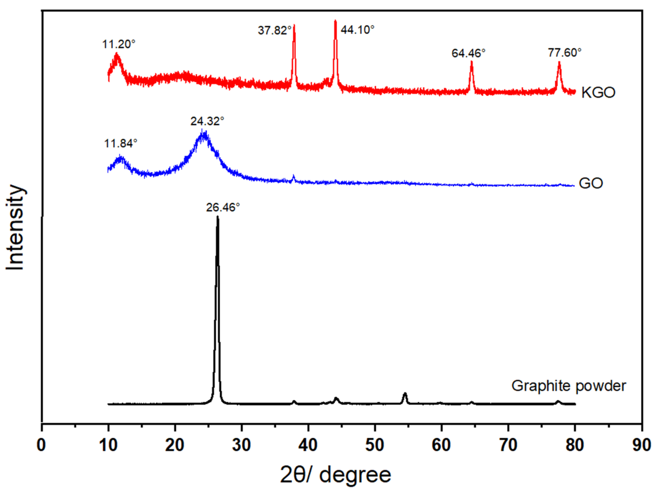
3.2. XRD Analysis
3.3. Thermogravimetric Analysis (TGA)
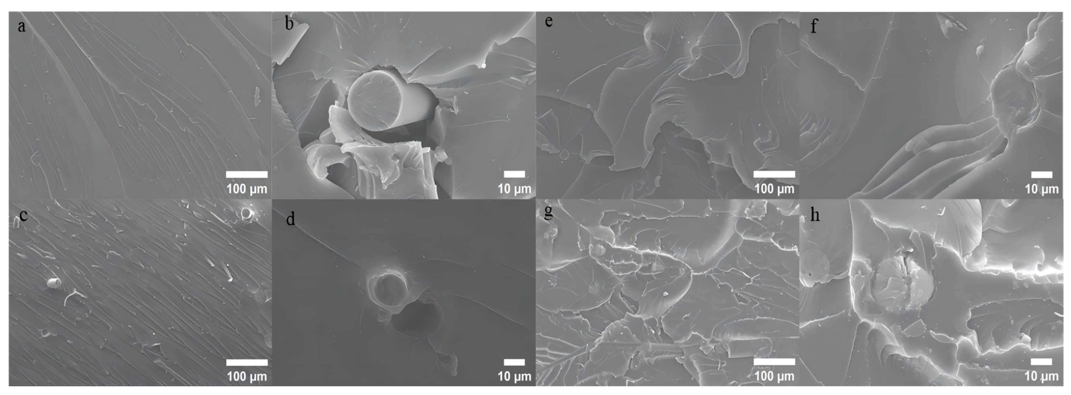
3.4. Morphology Analysis of Composites
3.5. Corrosion Resistance and Mechanical Properties of Composite Materials
3.5.1. Effect of KGO on Water Absorption of Composites
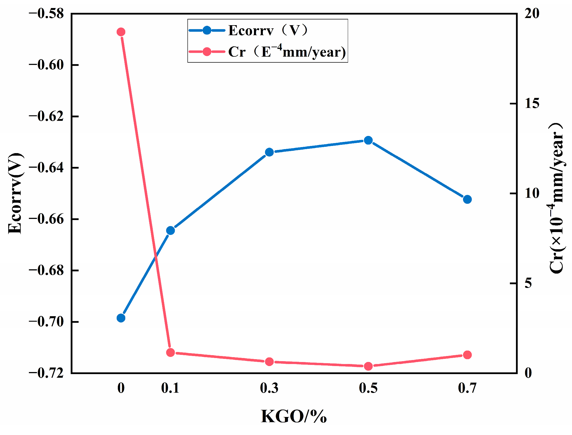
3.5.2. Effect of KGO on Corrosion Resistance of Composite Materials
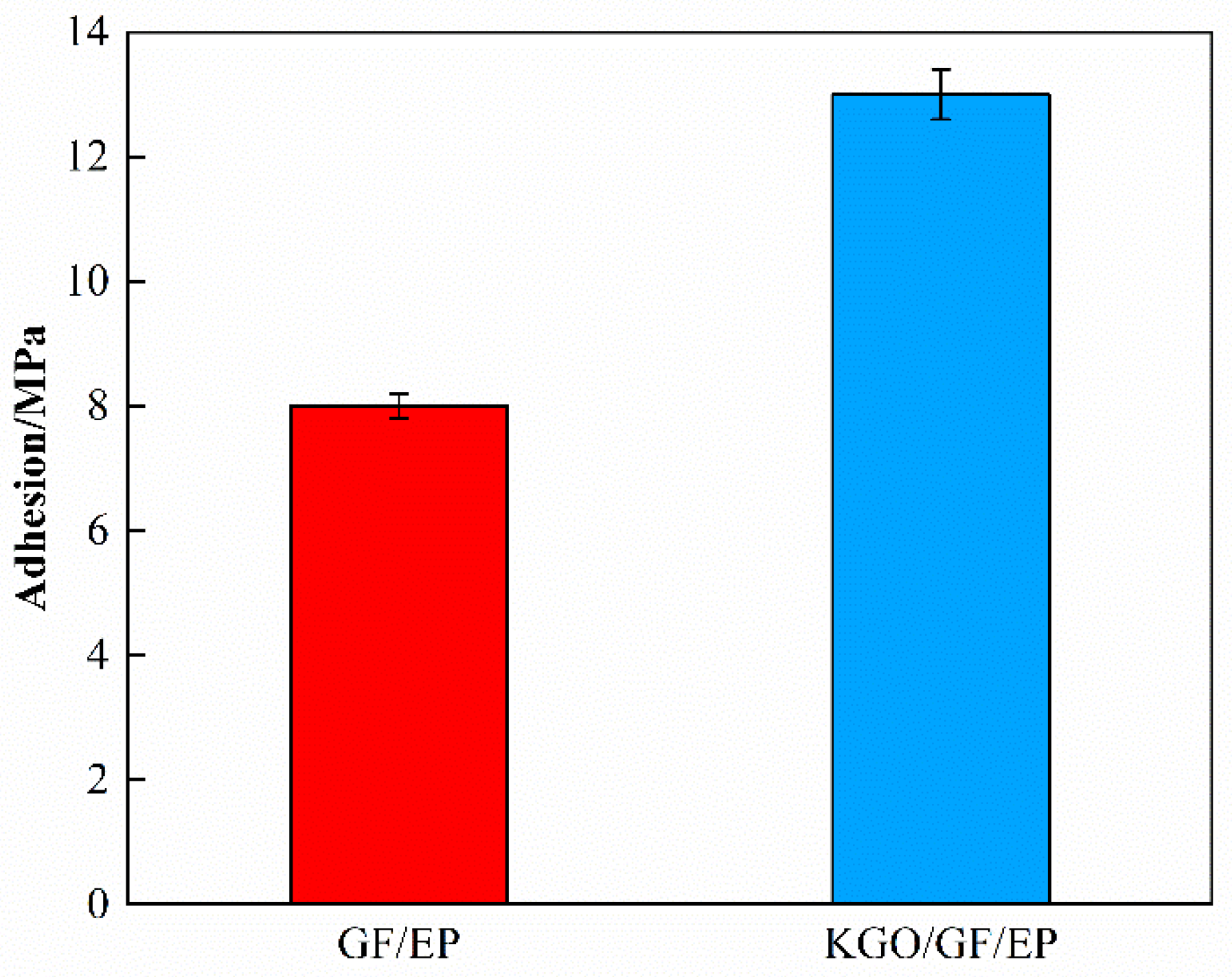
3.5.3. Effect of KGO on Adhesion Property of Composite Materials
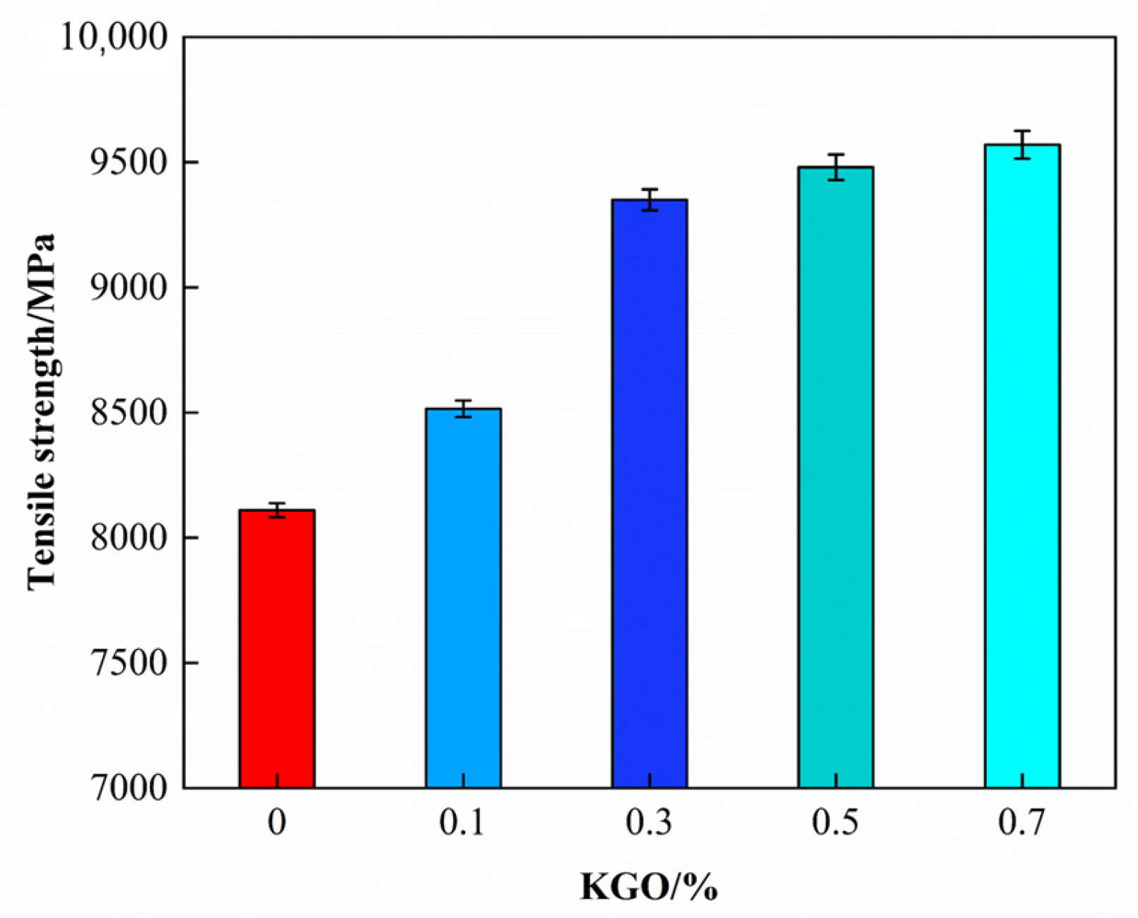
3.5.4. Effect of KGO on Mechanical Properties of Composites
3.6. Study on Mechanical Properties of Composite Materials by KGF
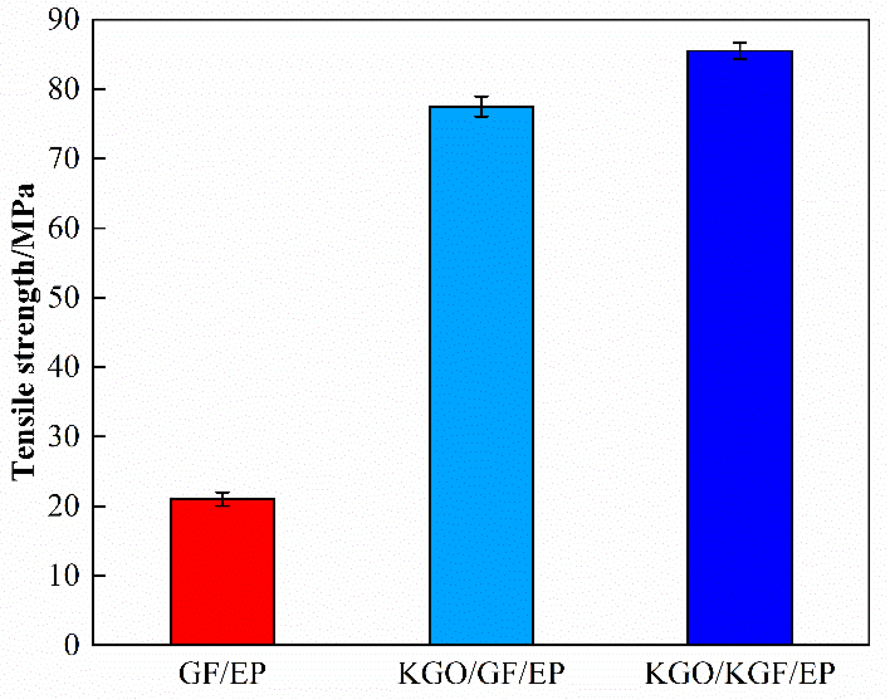
3.6.1. Tensile Strength Test Results
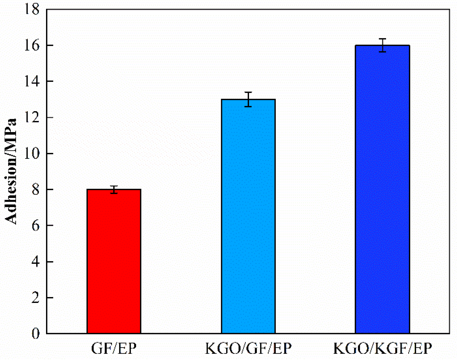
3.6.2. Adhesion Test Results
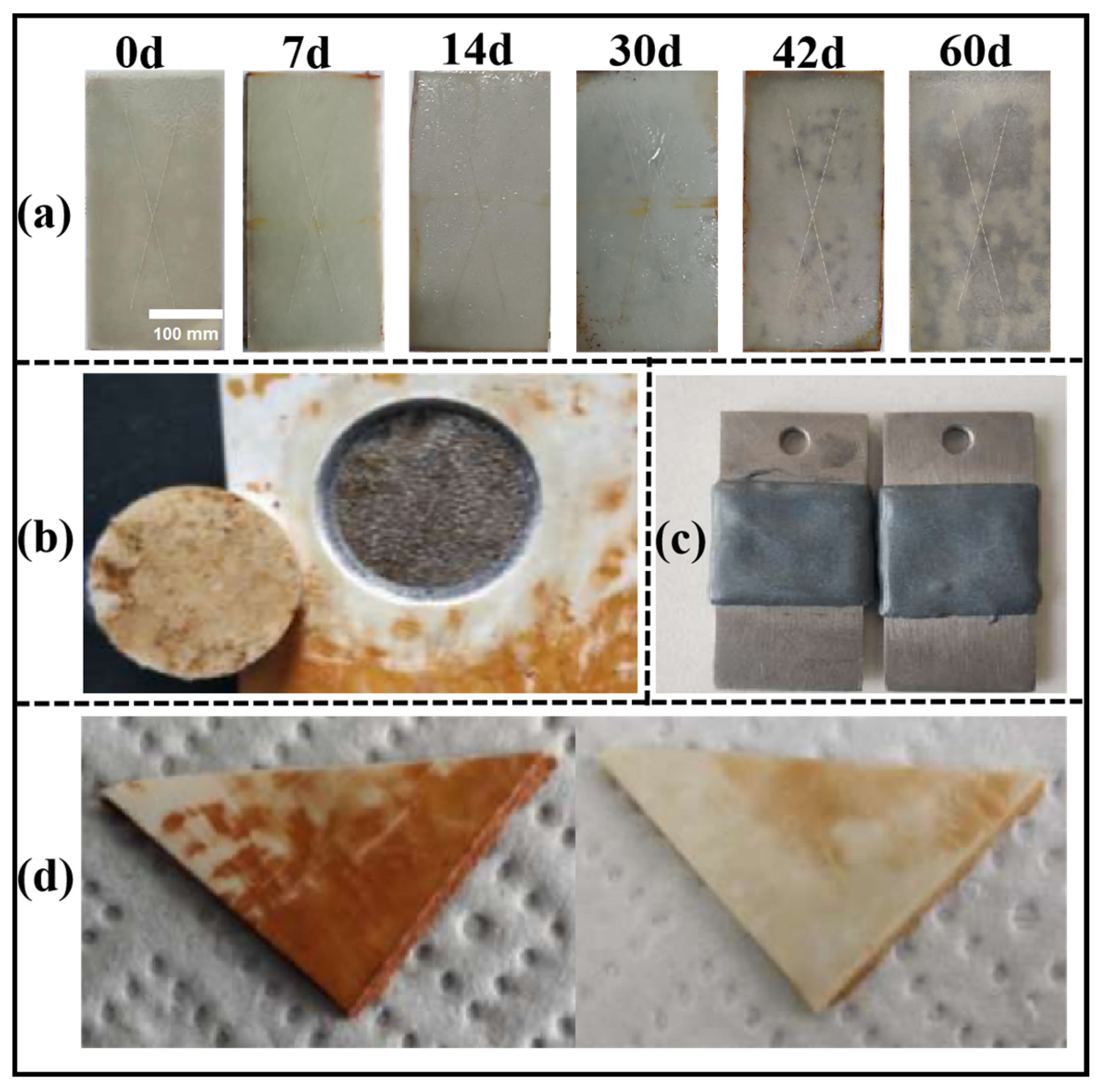
3.7. Test Results of Anticorrosive Properties of KGO/KGF/EP Composites

3.8. Numerical Simulation of Wind Load
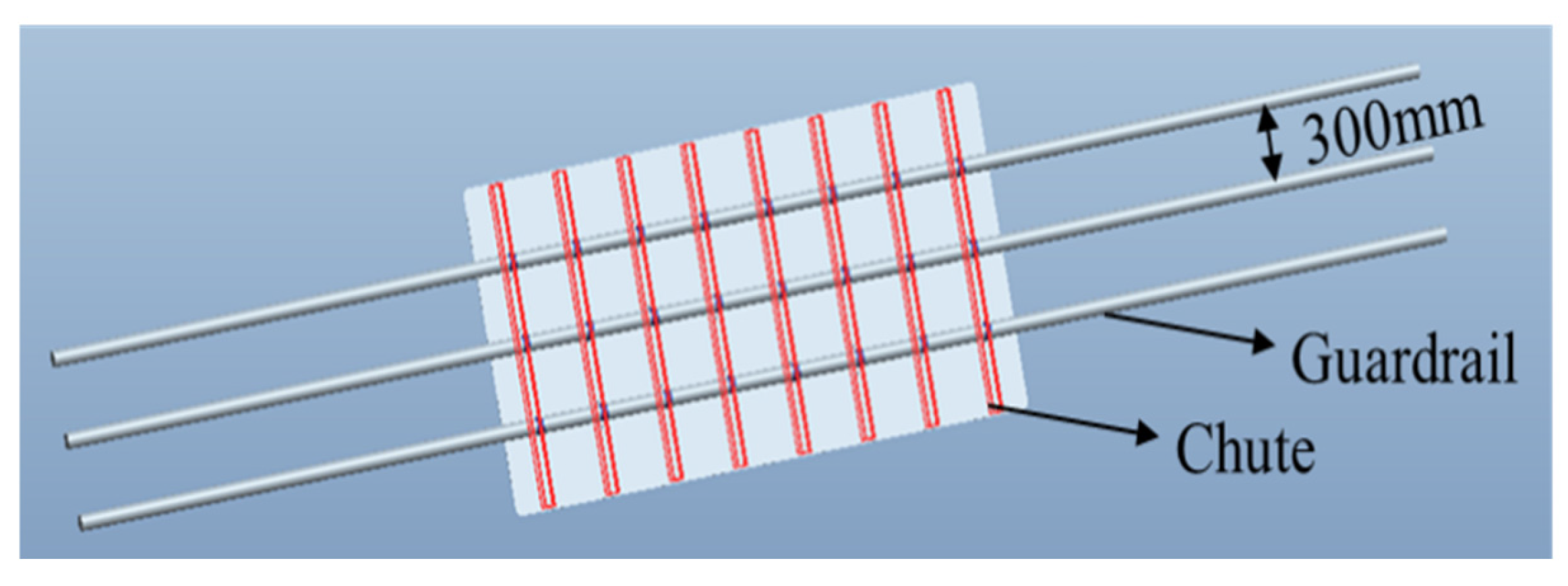
3.8.1. The Establishment of Numerical Simulation
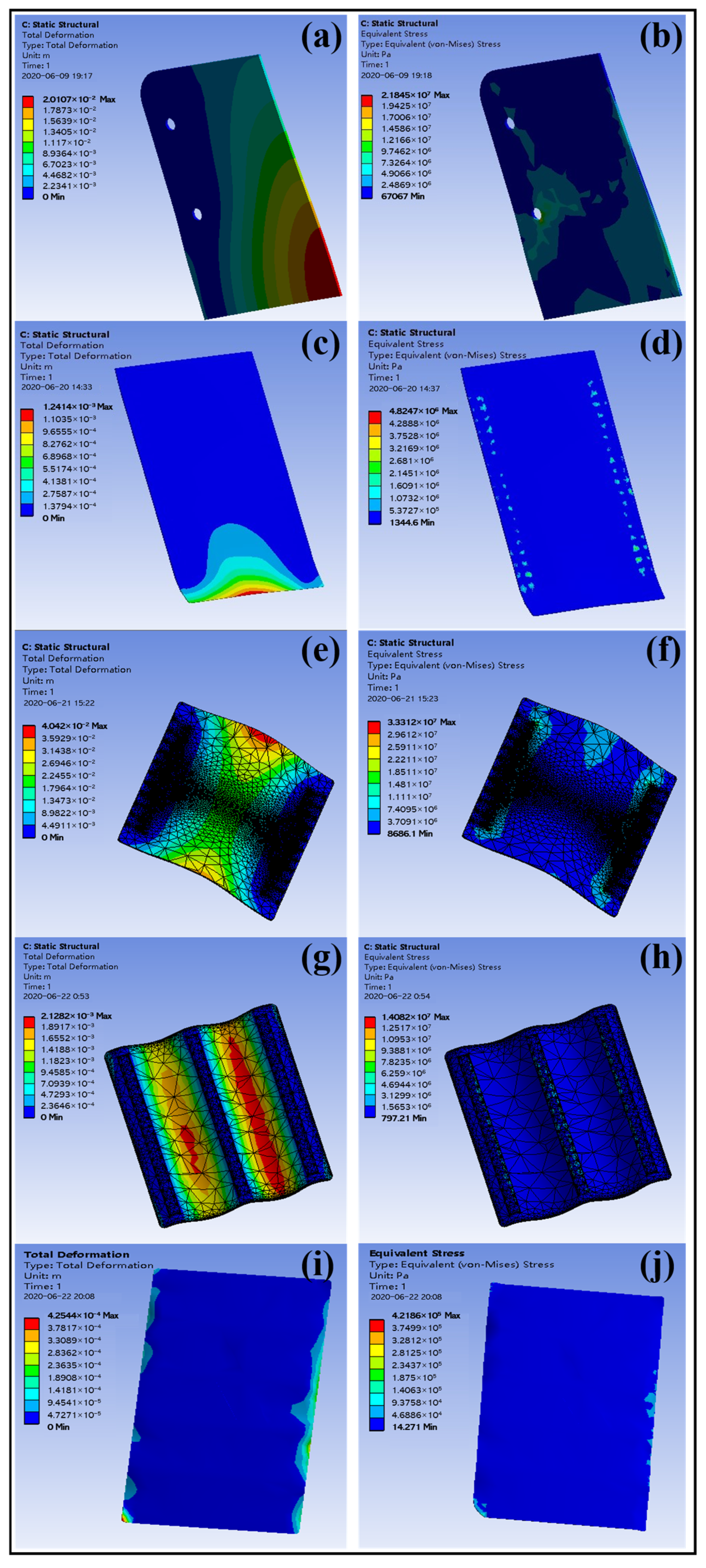
3.8.2. Fluid Dynamics Simulation Results and Data Analysis
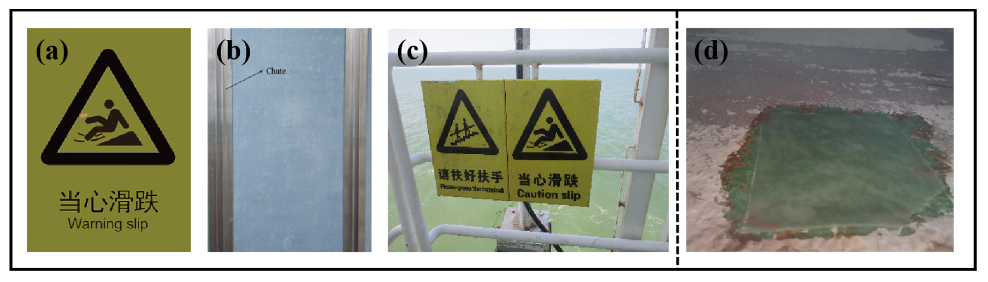
3.9. Practical Application of Composite Materials
4. Conclusions
Author Contributions
Funding
Institutional Review Board Statement
Informed Consent Statement
Data Availability Statement
Conflicts of Interest
References
- Liu, Y.; Chen, Y.; Zhao, H.; Teng, C. Characterization, dielectric properties, and mechanical properties of cyanate epoxy composites modified by KH550-AlOOH@GO. J. Mater. Sci. Mater. Electron. 2021, 32, 8890–8902. [Google Scholar] [CrossRef]
- Pourhashem, S.; Rashidi, A.; Vaezi, M.R.; Bagherzadeh, M.R. Excellent corrosion protection performance of epoxy composite coatings filled with amino-silane functionalized graphene oxide. Surf. Coat. Technol. 2017, 317, 1–9. [Google Scholar] [CrossRef]
- Zhou, T.; Zhang, J.; Zhao, J.; Qu, W.; Li, X.; Li, S.; Xing, B.; Fu, Y. In-situ grafted graphene oxide-based waterborne epoxy curing agent for reinforcement corrosion protection of waterborne epoxy coating. Surf. Coat. Technol. 2021, 412, 127043. [Google Scholar] [CrossRef]
- Parhizkar, N.; Shahrabi, T.; Ramezanzadeh, B. A new approach for enhancement of the corrosion protection properties and interfacial adhesion bonds between the epoxy coating and steel substrate through surface treatment by covalently modified amino functionalized graphene oxide film. Corros. Sci. 2017, 123, 55–75. [Google Scholar] [CrossRef]
- He, Y.; Chen, C.; Xiao, G.; Zhong, F.; Wu, Y.; He, Z. Improved corrosion protection of waterborne epoxy/graphene coating by combining non-covalent and covalent bonds. React. Funct. Polym. 2019, 137, 104–115. [Google Scholar] [CrossRef]
- Xiong, L.; Yu, M.; Li, Y.; Kong, X.; Li, S.; Liu, J. Modified salicylaldehyde@ZIF-8/graphene oxide for enhancing epoxy coating corrosion protection property on AA2024-T3. Prog. Org. Coat. 2020, 142, 105562. [Google Scholar] [CrossRef]
- Pourhashem, S.; Vaezi, M.R.; Rashidi, A.; Bagherzadeh, M.R. Distinctive roles of silane coupling agents on the corrosion inhibition performance of graphene oxide in epoxy coatings. Prog. Org. Coat. 2017, 111, 47–56. [Google Scholar] [CrossRef]
- Chen, Y.; Ren, B.; Gao, S.; Cao, R. The sandwich-like structures of polydopamine and 8-hydroxyquinoline coated graphene oxide for excellent corrosion resistance of epoxy coatings. J. Colloid Interface Sci. 2020, 565, 436–448. [Google Scholar] [CrossRef]
- Wu, W.; Xu, Y.; Wu, H.; Chen, J.; Li, M.; Chen, T.; Hong, J.; Dai, L. Synthesis of modified graphene oxide and its improvement on flame retardancy of epoxy resin. J. Appl. Polym. Sci. 2019, 137, 47710. [Google Scholar] [CrossRef]
- Fazli-Shokouhi, S.; Nasirpouri, F.; Khatamian, M. Polyaniline-modified graphene oxide nanocomposites in epoxy coatings for enhancing the anticorrosion and antifouling properties. J. Coat. Technol. Res. 2019, 16, 983–997. [Google Scholar] [CrossRef]
- Zhuowei, Z.; Meng, Z.; Wenjie, Z.; Jianfeng, H.; Heqing, F. Anti-corrosion epoxy/modified graphene oxide/glass fiber composite coating with dual physical barrier network. Prog. Org. Coat. 2022, 167, 106823. [Google Scholar] [CrossRef]
- Mehmet, B.; Mohamad, A.; Ahmet, E. A comparative study on the tensile and impact properties of Kevlar, carbon, and S-glass/epoxy composites reinforced with SiC particles. Mater. Res. Express 2018, 5, 025301. [Google Scholar] [CrossRef]
- Rahman, M.M.; Zainuddin, S.; Hosur, M.V.; Malone, J.E.; Salam, M.B.A.; Kumar, A.; Jeelani, S. Improvements in mechanical and thermo-mechanical properties of e-glass/epoxy composites using amino functionalized MWCNTs. Compos. Struct. 2012, 94, 2397–2406. [Google Scholar] [CrossRef]
- Matykiewicz, D. Hybrid Epoxy Composites with Both Powder and Fiber Filler: A Review of Mechanical and Thermomechanical Properties. Materials 2020, 13, 1802. [Google Scholar] [CrossRef]
- GB/T 1733-1993; Paints—Test Method for Water Resistance of Films. Standards Press of China: Beijing, China, 1993.
- GB/T 9274-1988; Paints and Varnishes—Determination of Resistance to Liquid Media. Standards Press of China: Beijing, China, 1988.
- GB/T 1771-2007; Paints and Varnishes—Determination of Resistance to Neutral Salt Spray. Standards Press of China: Beijing, China, 2007.
- GB/T 1447-2005; Fiber-Reinforced Plastics Composites—Determination of Tensile Properties. Standards Press of China: Beijing, China, 2005.
- GB/T 1446-2005; Fiber-Reinforced Plastics Composites—General Rules for Test Methods. Standards Press of China: Beijing, China, 2005.
- GB/T 5210-2006; Paints and Varnishes—Pull-Off Test for Adhesion. Standards Press of China: Beijing, China, 2006.
- ASTM D570-98(2005); Standard Test Method for Water Absorption of Plastics. ASTM International: West Conshohocken, PA, USA, 2005.
- Kazemi, F.; Asgarkhani, N.; Shafighfard, T.; Jankowski, R.; Yoo, D.-Y. Machine-Learning Methods for Estimating Performance of Structural Concrete Members Reinforced with Fiber-Reinforced Polymers. Arch. Comput. Methods Eng. 2024, 32, 571–603. [Google Scholar] [CrossRef]
- Ashori, A.; Fallah, A.; Ghiyasi, M.; Rabiee, M. Reinforcing effects of functionalized graphene oxide on glass fiber/epoxy composites. Polym. Compos. 2017, 39, E2324–E2333. [Google Scholar] [CrossRef]
- Versaci, M.; Laganà, F.; Morabito, F.C.; Palumbo, A.; Angiulli, G. Adaptation of an Eddy Current Model for Characterizing Subsurface Defects in CFRP Plates Using FEM Analysis Based on Energy Functional. Mathematics 2024, 12, 2854. [Google Scholar] [CrossRef]
- Hass, J.; de Heer, W.A.; Conrad, E.H. The growth and morphology of epitaxial multilayer graphene. J. Phys. Condens. Matter 2008, 20, 323202. [Google Scholar] [CrossRef]
- Chang, K.-C.; Hsu, M.-H.; Lu, H.-I.; Lai, M.-C.; Liu, P.-J.; Hsu, C.-H.; Ji, W.-F.; Chuang, T.-L.; Wei, Y.; Yeh, J.-M.; et al. Room-temperature cured hydrophobic epoxy/graphene composites as corrosion inhibitor for cold-rolled steel. Carbon 2014, 66, 144–153. [Google Scholar] [CrossRef]
- Wu, L.-K.; Zhang, J.-T.; Hu, J.-M.; Zhang, J.-Q. Improved corrosion performance of electrophoretic coatings by silane addition. Corros. Sci. 2012, 56, 58–66. [Google Scholar] [CrossRef]
- Bakhshandeh, E.; Jannesari, A.; Ranjbar, Z.; Sobhani, S.; Saeb, M.R. Anti-corrosion hybrid coatings based on epoxy–silica nano-composites: Toward relationship between the morphology and EIS data. Prog. Org. Coat. 2014, 77, 1169–1183. [Google Scholar] [CrossRef]
- SH/T 3022-2019; Design Standard for Corrosion Resistance of Coatings for Petrochemical Equipment and Pipelines. China Petrochemical Press: Beijing, China, 2019.


| Raw Material | Mass Fraction (wt.%) |
|---|---|
| Epoxy resin | 45~70 |
| Photoinitiator UVI16992 | 0.08~0.35 |
| Infiltrating agent | 0.1~0.5 |
| Magnesia paste | 0.2~0.5 |
| Aluminum hydroxide | 10~20 |
| Quartz powder | 10~20 |
| Modified glass fiber | 12 |
| Modified graphene oxide | 0.5 |
| Sample | Wt. (KGO)/% | Weight of Sample Before Immersion/mg | Weight of Sample After Immersion/mg | Water Absorption Rate/% |
|---|---|---|---|---|
| 1 | 0 | 250.5 ± 0.12 | 263.4 ± 0.25 | 5.15 ± 0.20 |
| 2 | 0.1% | 233.4 ± 0.15 | 245.4 ± 0.30 | 5.14 ± 0.22 |
| 3 | 0.3% | 258.9 ± 0.10 | 270.2 ± 0.18 | 4.36 ± 0.15 |
| 4 | 0.5% | 369.7 ± 0.20 | 383.2 ± 0.35 | 3.65 ± 0.12 |
| 5 | 0.7% | 272.3 ± 0.18 | 284.5 ± 0.28 | 4.48 ± 0.18 |
| Signboard Specification (mm × mm) | Fixed Mode (Chute Width 60 mm) | Deformation (mm) | Stress (MPa) | Allowable Stress (MPa) |
|---|---|---|---|---|
| 500 × 350 | Two side chutes fixed | 20.1 | 21.8 | Longitudinal tensile strength × 0.6 (Safety factor) = 85.6 × 0.6 = 51.4 |
| 600 × 450 | Two side chutes fixed | 1.24 | 48.2 | |
| 900 × 600 | Two side chutes fixed | 40.4 | 33.3 | |
| 1100 × 900 | The three chutes are evenly distributed | 2.13 | 14.08 | |
| 2400 × 1200 | The three chutes are evenly distributed | 0.425 | 42.2 |
Disclaimer/Publisher’s Note: The statements, opinions and data contained in all publications are solely those of the individual author(s) and contributor(s) and not of MDPI and/or the editor(s). MDPI and/or the editor(s) disclaim responsibility for any injury to people or property resulting from any ideas, methods, instructions or products referred to in the content. |
© 2025 by the authors. Licensee MDPI, Basel, Switzerland. This article is an open access article distributed under the terms and conditions of the Creative Commons Attribution (CC BY) license (https://creativecommons.org/licenses/by/4.0/).
Share and Cite
Lv, G.; Xiao, P.; Su, Y.; Liu, X. Silanized Graphene Oxide/Glass Fiber-Modified Epoxy Composite with Excellent Anti-Corrosion and Mechanical Properties as Offshore Oil Platform Safety Signs. Materials 2025, 18, 1920. https://doi.org/10.3390/ma18091920
Lv G, Xiao P, Su Y, Liu X. Silanized Graphene Oxide/Glass Fiber-Modified Epoxy Composite with Excellent Anti-Corrosion and Mechanical Properties as Offshore Oil Platform Safety Signs. Materials. 2025; 18(9):1920. https://doi.org/10.3390/ma18091920
Chicago/Turabian StyleLv, Guanglei, Peng Xiao, Yuhua Su, and Xinmei Liu. 2025. "Silanized Graphene Oxide/Glass Fiber-Modified Epoxy Composite with Excellent Anti-Corrosion and Mechanical Properties as Offshore Oil Platform Safety Signs" Materials 18, no. 9: 1920. https://doi.org/10.3390/ma18091920
APA StyleLv, G., Xiao, P., Su, Y., & Liu, X. (2025). Silanized Graphene Oxide/Glass Fiber-Modified Epoxy Composite with Excellent Anti-Corrosion and Mechanical Properties as Offshore Oil Platform Safety Signs. Materials, 18(9), 1920. https://doi.org/10.3390/ma18091920