
Utilizing Fly Ash from Coal-Fired Power Plants to Join ZrO2 and Crofer by Reactive Air Brazing


Abstract
:1. Introduction
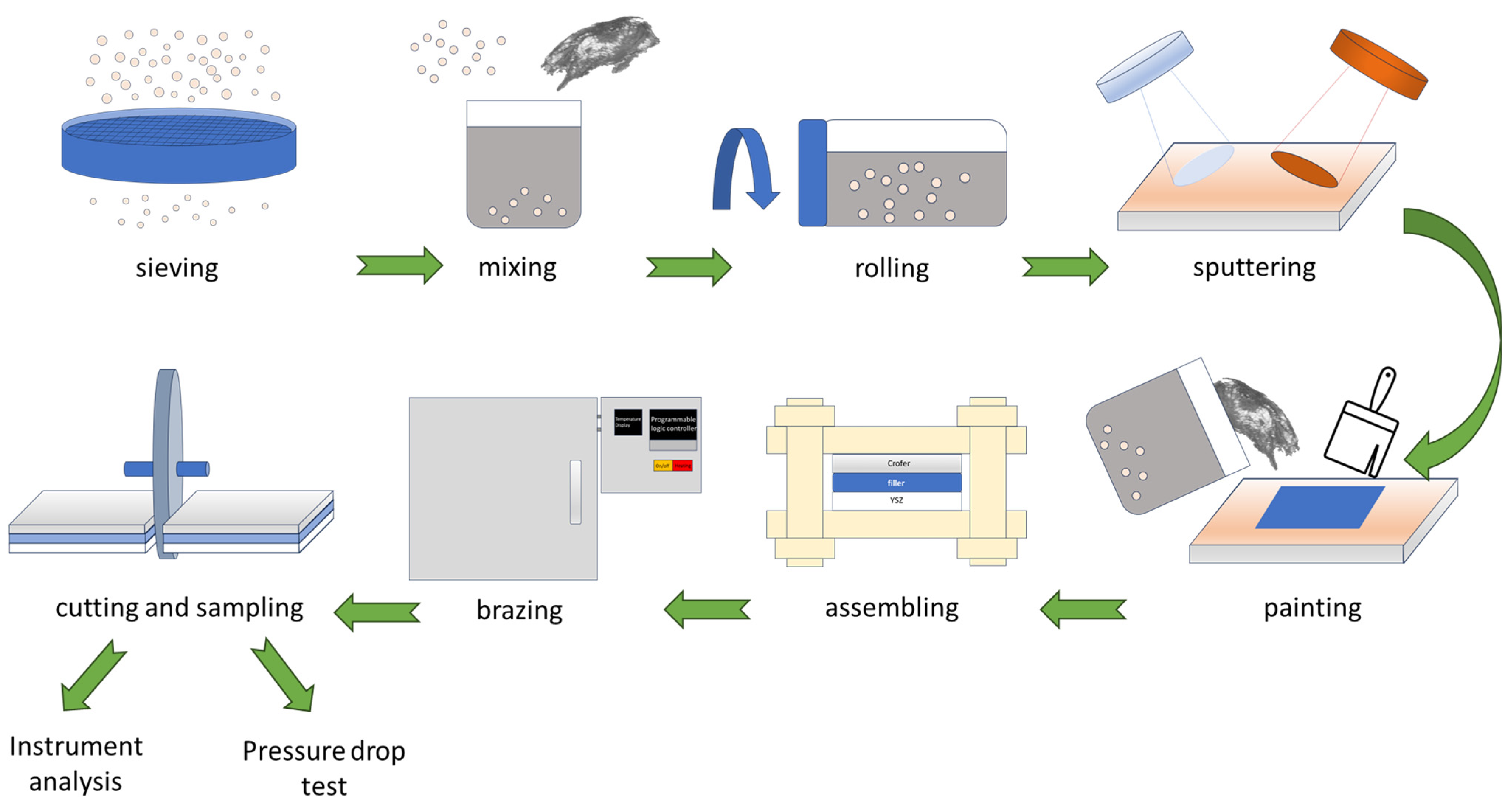
2. Materials and Experimental Procedures
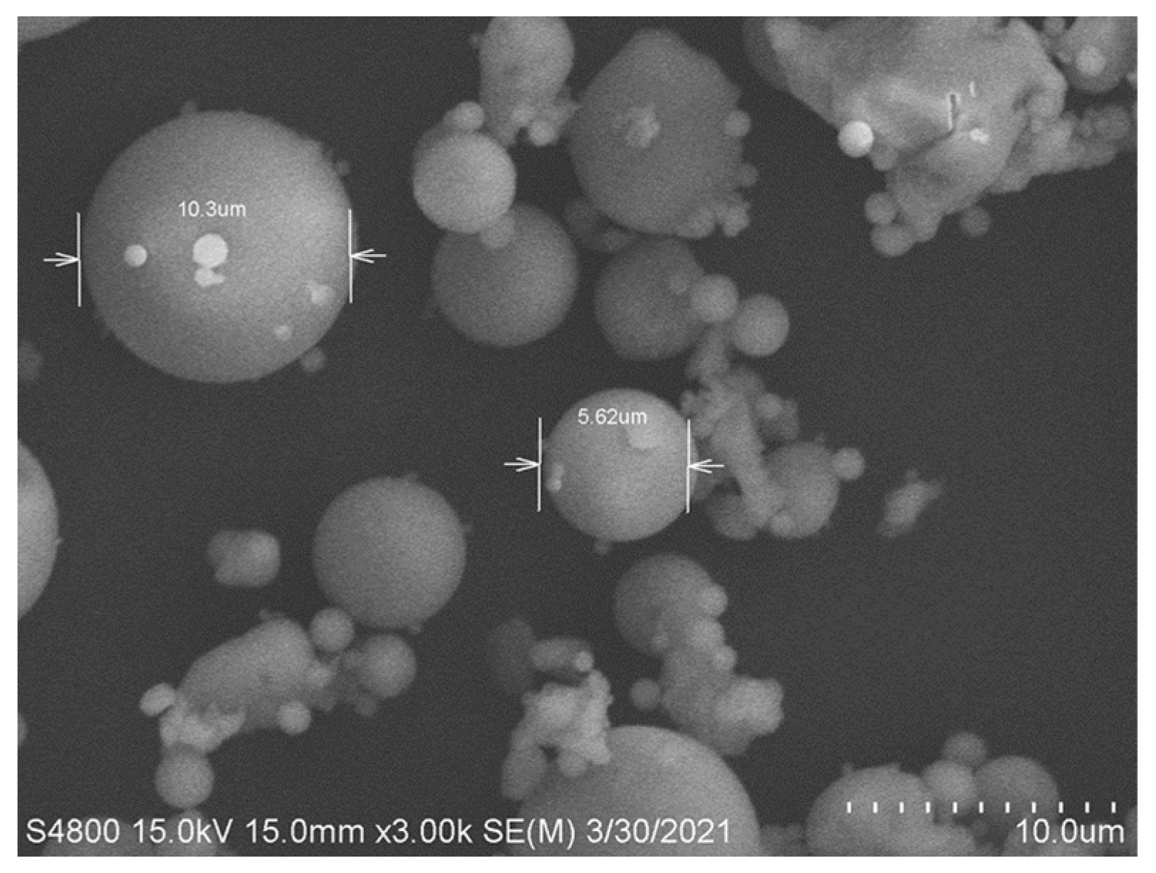
2.1. Materials
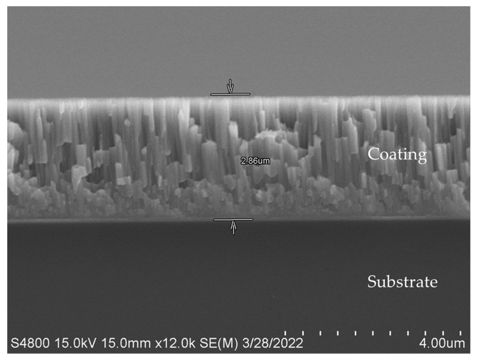
2.2. Sputtering of Two Substrates
2.3. Sample Preparation and Analyses After Brazing
2.4. Airtight Test
3. Results and Discussion
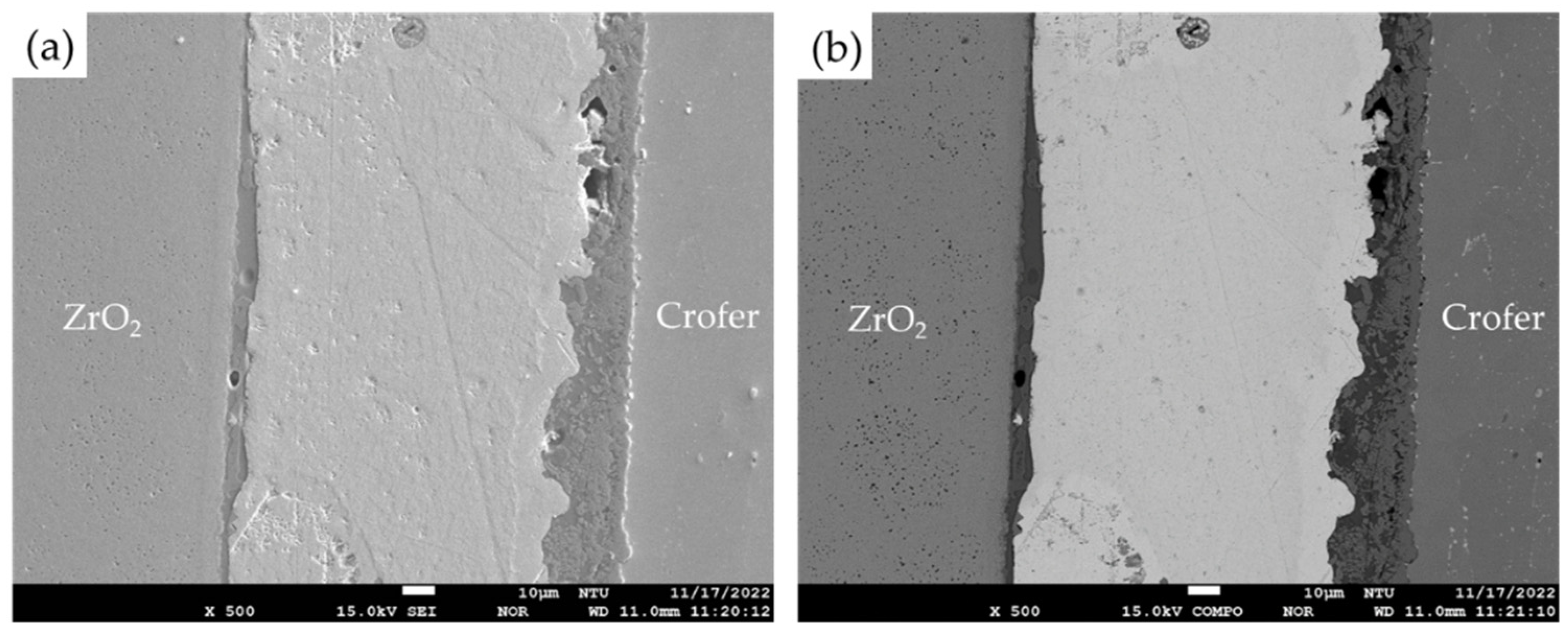
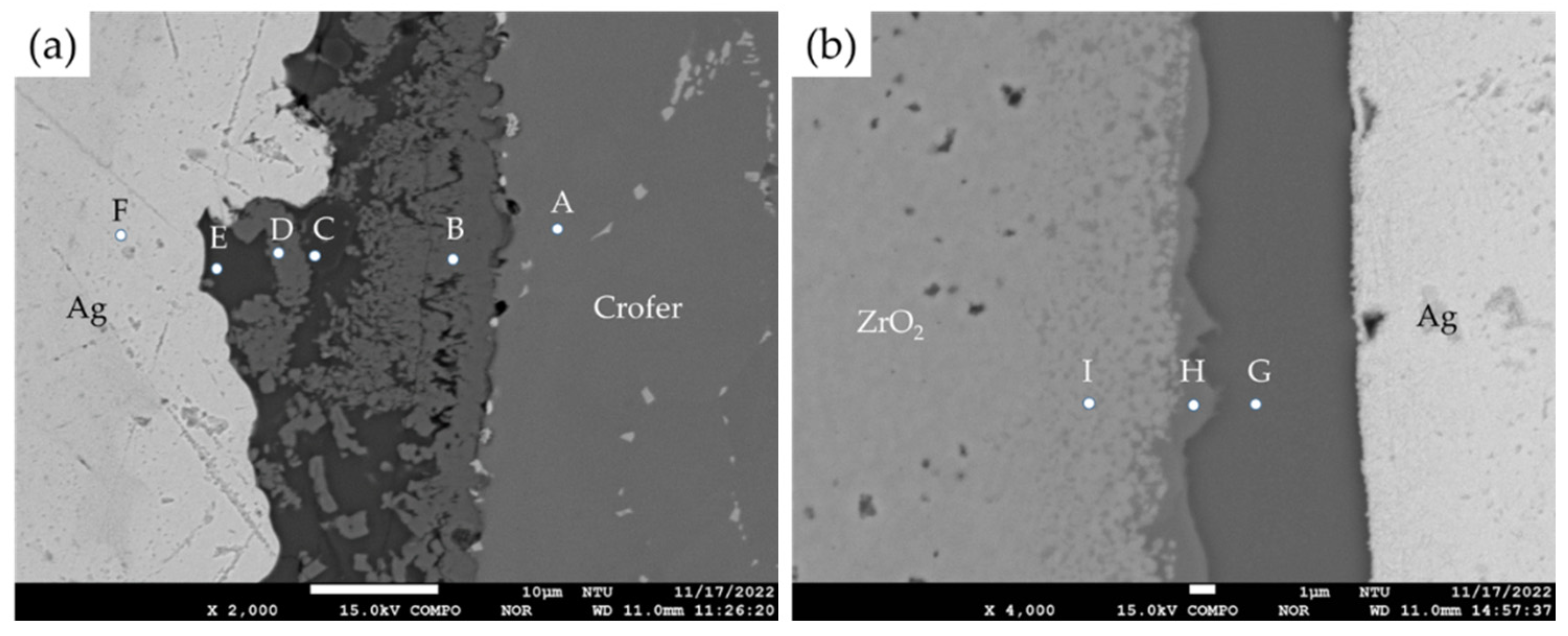
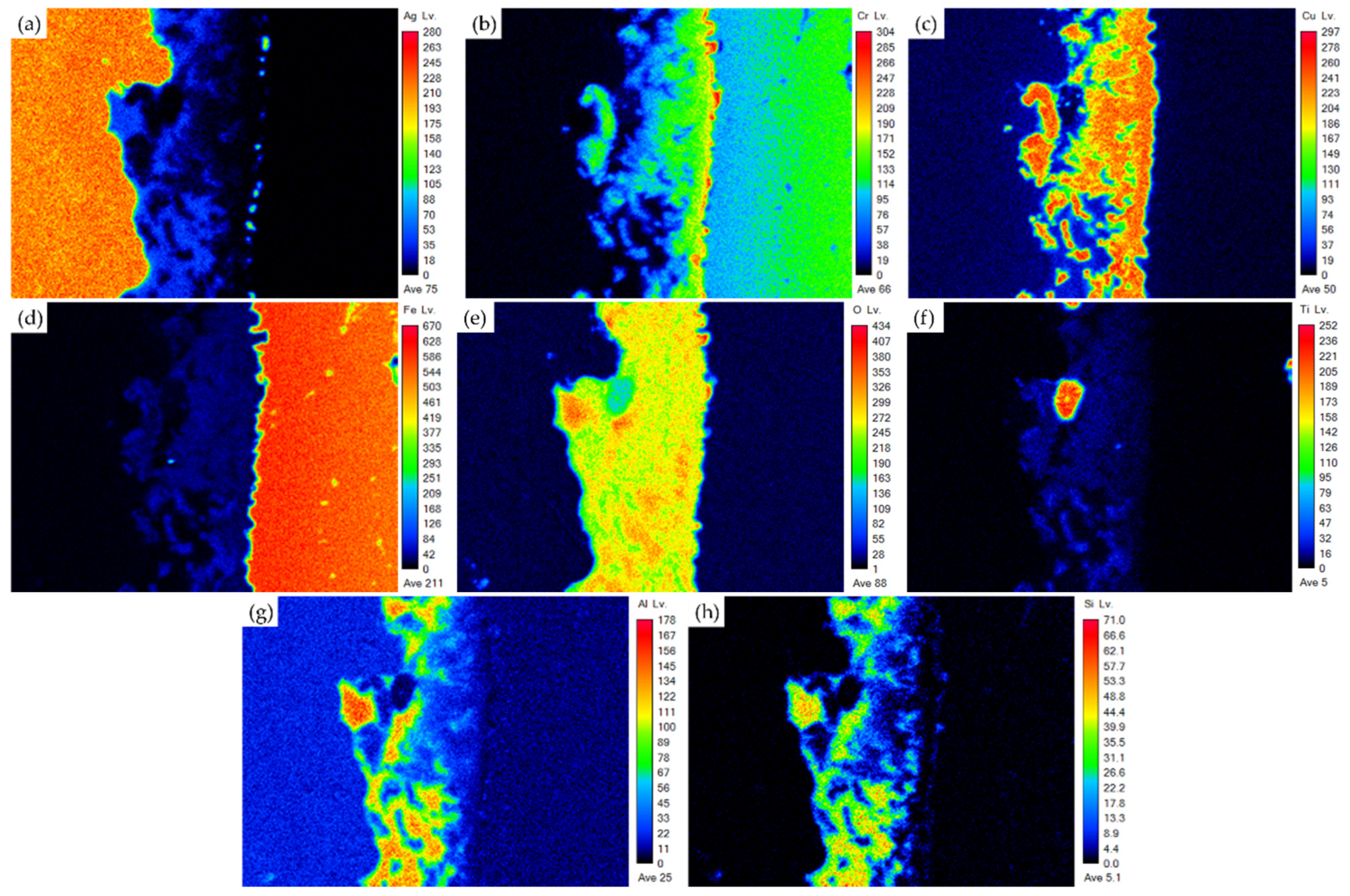
3.1. Microstructural Observation of the RAB Joint with 5 wt% Fly Ash Addition
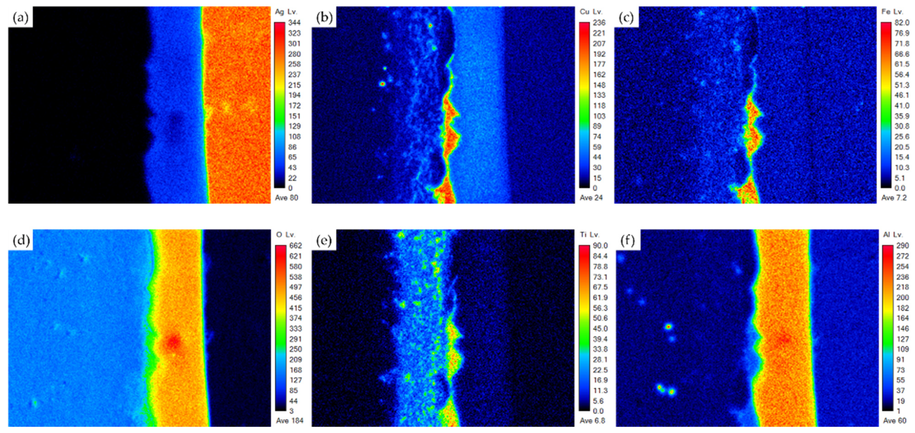
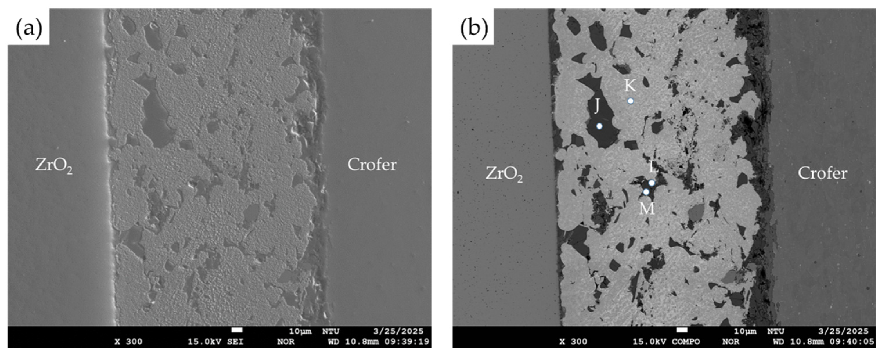
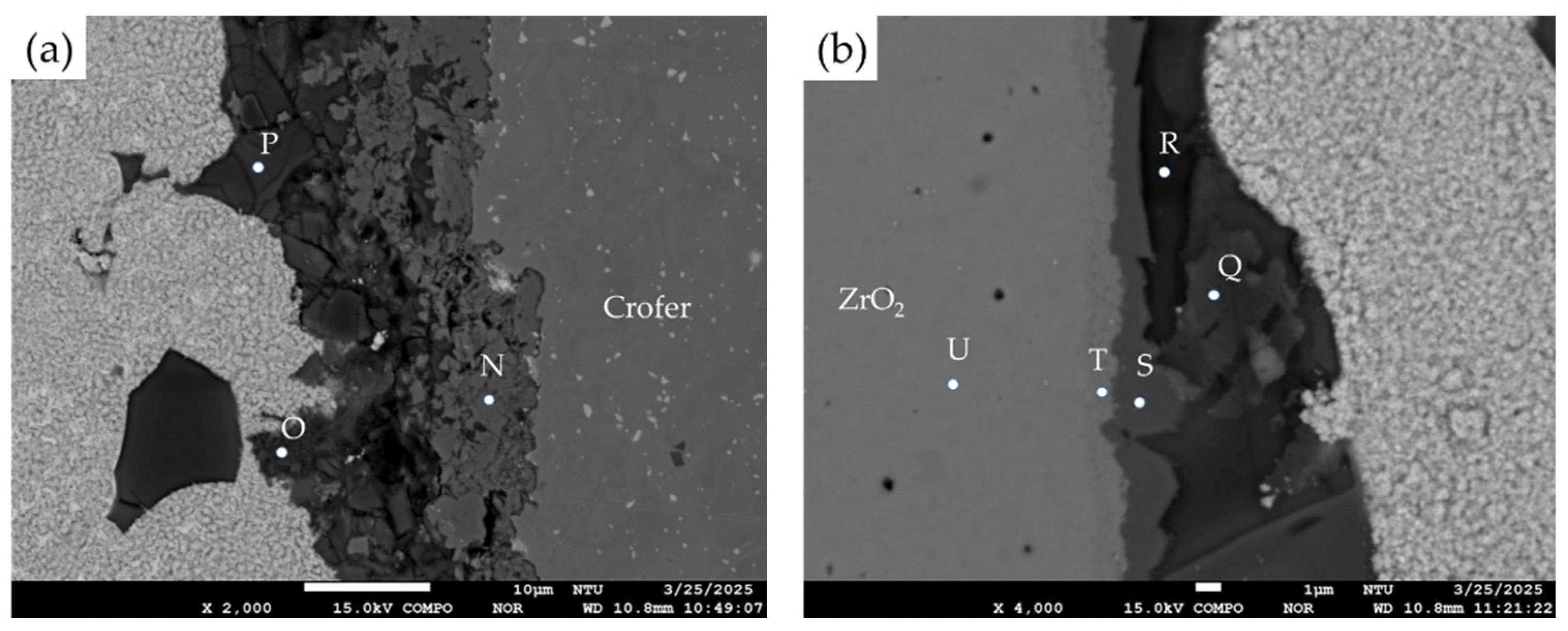
3.2. Microstructural Observation of the RAB Joint with 10 wt% Fly Ash Addition
3.3. Airtightness Test of the Air-Brazed Joint
4. Conclusions
- The Ag-rich phase dominates the brazed zone in the 5% fly ash RAB joint. The interfacial reaction layers contain the oxidation of the Cu-Ti coating layer, Crofer alloy, and the Si/Al-rich oxides from the fly ash particles. Good bonding among the ZrO2, Ag-rich braze with 5 wt% fly ash and Crofer alloy was achieved in the experiment.
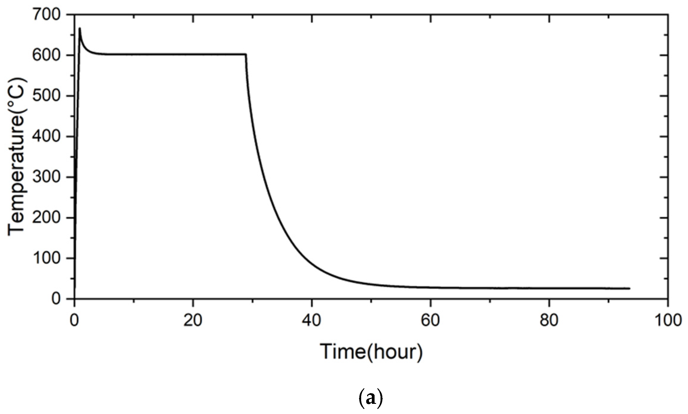
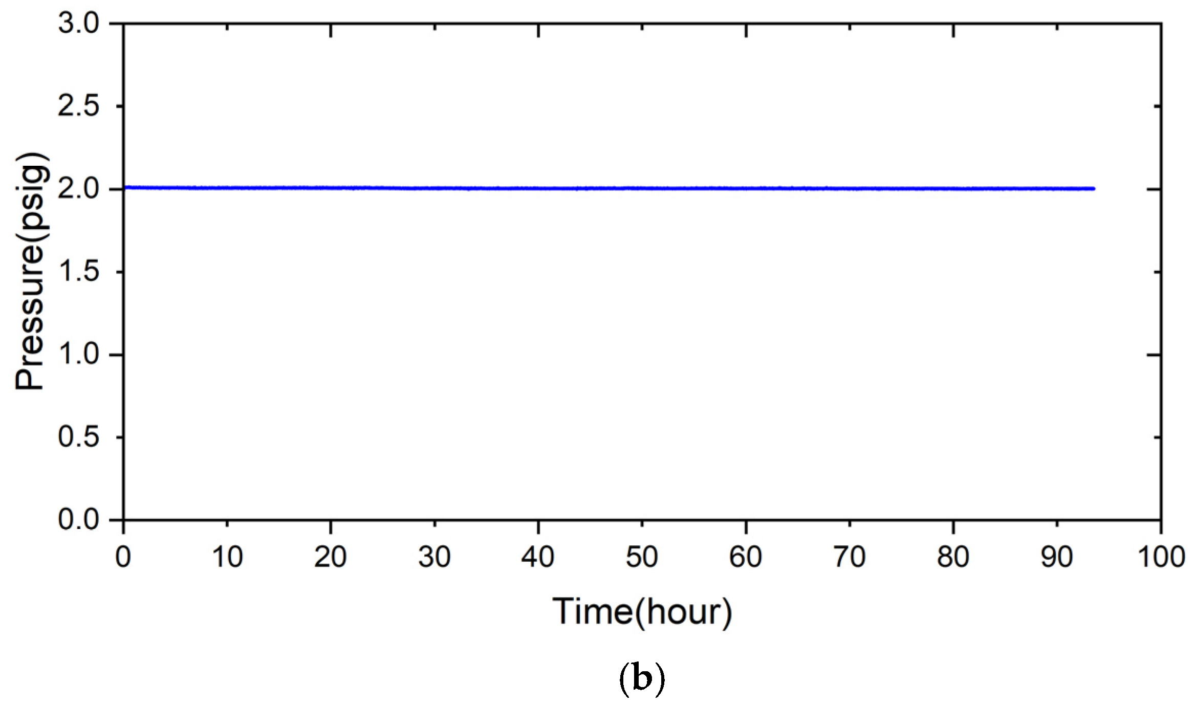
- The 5% fly ash RAB joint maintained airtightness for 280 h under 2 psig helium at room temperature. When the test temperature was raised to 600 °C for 24 h, the pressure of the joint assembly still did not drop. After the test was performed at 700 °C for 24 h, the pressure of the joint assembly decreased slightly, with a pressure drop slope of 8.14 × 10⁻⁴ psig/h.
- When the fly ash addition was increased to 10 wt%, the joint assembly was no longer leak-free at room temperature. There were many visible voids and cracks in the brazed zone and at both interfaces, ZrO2/braze and braze/Crofer. A high volume fraction of the fly ash particles results in many brittle Si/Al-rich oxides in the joint after RAB, and the fracture of these oxides significantly deteriorates the airtightness of the joint.
- Compared with the reactive air brazed joint using Ag paste without fly ash, the brazed joint with 5 wt% fly ash Ag-rich filler paste demonstrated comparable performance in the airtightness test. Furthermore, adding fly ash into the Ag-based paste presents the advantages of promoting sustainability and recycling waste materials.
Author Contributions
Funding
Institutional Review Board Statement
Informed Consent Statement
Data Availability Statement
Acknowledgments
Conflicts of Interest
References
- International Energy Agency. Coal 2024 Analysis and Forecast to 2027. 2024. Available online: https://www.iea.org/reports/coal-2024 (accessed on 1 March 2025).
- Arpita, B.; Sharon, P.; Aiswarya, A.M.; Arash, A.; Melanie, S.; Sorakrich, T. Physical, chemical, and geotechnical properties of coal fly ash: A global review. Case Stud. Constr. Mater. 2019, 11, e00263. [Google Scholar] [CrossRef]
- Banda, M.F.; Matabane, D.L.; Munyengabe, A. A phytoremediation approach for the restoration of coal fly ash polluted sites: A review. Heliyon 2024, 10, e40741. [Google Scholar] [CrossRef]
- Kelechi, S.E.; Adamu, M.; Uche, O.A.U.; Okokpujie, I.P.; Ibrahim, Y.E.; Obianyo, I.I. A comprehensive review on coal fly ash and its application in the construction industry. Cogent Eng. 2022, 9, 2114201. [Google Scholar] [CrossRef]
- Van der Merwe, E.M.; Prinsloo, L.C.; Mathebula, C.L.; Swart, H.C.; Coetsee, E.; Doucet, F.J. Surface and bulk characterization of an ultrafine South African coal fly ash with reference to polymer applications. Appl. Surf. Sci. 2014, 317, 73–83. [Google Scholar] [CrossRef]
- Liang, J.; Tang, Z.; Qi, F.; Jiang, W.; Lao, X.; Miao, L.; Tang, H.; Liu, J.; Bao, Z. Preparation of foam ceramics from solid wastes: A study on the relationship between firing regime and properties by grey system theory. J. Mater. Res. Technol. 2023, 26, 58–70. [Google Scholar] [CrossRef]
- Wei, M.; Liu, S.; Zhou, Y.; An, S.; Sun, X. Preparation and properties of CaO-Al2O3-SiO2-Fe2O3 system foam ceramics from fly ash and steel slag. Ceram. Int. 2025, 51, 11672–11683. [Google Scholar] [CrossRef]
- Bayat, O. Characterisation of Turkish fly ashes. Fuel 1998, 77, 1059–1066. [Google Scholar] [CrossRef]
- Nyale, S.M.; Babajide, O.O.; Birch, G.D.; Böke, N.; Petrik, L.F. Synthesis and characterization of coal fly ash-based foamed geopolymer. Procedia Environ. Sci. 2013, 18, 722–730. [Google Scholar] [CrossRef]
- Wang, S. Quantitative kinetics of pozzolanic reactions in coal/cofired biomass fly ashes and calcium hydroxide (CH) mortars. Constr. Build. Mater. 2014, 51, 364–371. [Google Scholar] [CrossRef]
- Lothenbach, B.; Scrivener, K.; Hooton, R.D. Supplementary cementitious materials. Cem. Concr. Res. 2011, 41, 1244–1256. [Google Scholar] [CrossRef]
- Luo, Y.; Wu, Y.; Ma, S. Utilization of coal fly ash in China: A mini-review on challenges and future directions. Environ. Sci. Pollut. Res. 2021, 28, 18727–18740. [Google Scholar] [CrossRef]
- Lu, X.; Liu, B.; Zhang, Q.; Wen, Q.; Wang, S.; Xiao, K.; Zhang, S. Recycling of coal fly ash in building materials: A review. Minerals 2022, 13, 25. [Google Scholar] [CrossRef]
- Vilakazi, A.Q.; Ndlovu, S.; Chipise, L.; Shemi, A. The recycling of coal fly ash: A review on sustainable developments and economic considerations. Sustainability 2022, 14, 1958. [Google Scholar] [CrossRef]
- Gollakota, A.R.K.; Volli, V.; Munagapati, V.S.; Wen, J.C.; Shu, C.M. Synthesis of novel ZSM-22 zeolite from Taiwanese coal fly ash for the selective separation of Rhodamine 6G. J. Mater. Res. Technol. 2020, 9, 15381–15393. [Google Scholar] [CrossRef]
- Zhang, B.; Maloney, D.; Harun, N.F.; Zhou, N.; Pezzini, P.; Medam, A.; Hovsapian, R.; Bayham, S.; Tucker, D. Rapid load transition for integrated solid oxide fuel cell—Gas turbine (SOFC-GT) energy systems: A demonstration of the potential for grid response. Energy Convers Manag. 2022, 258, 115544. [Google Scholar] [CrossRef]
- Wang, S.; Ma, J.; Li, W.; Khayatnezhad, M.; Rouyendegh, B.D. An optimal configuration for hybrid SOFC, gas turbine, and Proton Exchange Membrane Electrolyzer using a developed Aquila Optimizer. Int. J. Hydrogen Energy 2022, 47, 8943–8955. [Google Scholar] [CrossRef]
- Selvam, K.; Komatsu, Y.; Sciazko, A.; Kaneko, S.; Shikazono, N. Thermodynamic analysis of 100% system fuel utilization solid oxide fuel cell (SOFC) system fueled with ammonia. Energy Convers. Manag. 2021, 249, 114839. [Google Scholar] [CrossRef]
- Singh, R.N. High-temperature seals for solid oxide fuel cells (SOFC). J. Mater. Eng. Perform. 2006, 15, 422–426. [Google Scholar] [CrossRef]
- Lessing, P.A. A review of sealing technologies applicable to solid oxide electrolysis cells. J. Mater. Sci. 2007, 42, 3465–3476. [Google Scholar] [CrossRef]
- Wang, S.F.; Hsu, Y.F.; Liao, Y.L.; Yang, Y.J.; Jasiński, P. Physical and sealing properties of BaO–Al2O3–SiO2–CaO–V2O5 glasses for solid oxide fuel cell applications. Int. J. Hydrogen Energy 2022, 47, 10044–10055. [Google Scholar] [CrossRef]
- Fergus, J.W. Sealants for solid oxide fuel cells. J. Power Sources 2005, 147, 46–57. [Google Scholar] [CrossRef]
- Liu, W.; Sun, X.; Khaleel, M.A. Predicting Young’s modulus of glass/ceramic sealant for solid oxide fuel cell considering the combined effects of aging, micro-voids and self-healing. J. Power Sources 2008, 185, 1193–1200. [Google Scholar] [CrossRef]
- Kerstan, M.; Rüssel, C. Barium silicates as high thermal expansion seals for solid oxide fuel cells studied by high-temperature X-ray diffraction (HT-XRD). J. Power Sources 2011, 196, 7578–7584. [Google Scholar] [CrossRef]
- Caron, N.; Bianchi, L.; Méthout, S. Development of a functional sealing layer for SOFC applications. J. Therm. Spray Technol. 2008, 17, 598–602. [Google Scholar] [CrossRef]
- Darsell, J.T.; Weil, K.S. High temperature strength of YSZ joints brazed with palladium silver copper oxide filler metals. Int. J. Hydrogen Energy 2011, 36, 4519–4524. [Google Scholar] [CrossRef]
- Hardy, J.S.; Kim, J.Y.; Thomsen, E.C.; Weil, K.S. Improved wetting of mixed ionic/electronic conductors used in electrochemical devices with ternary air braze filler metals. J. Electrochem. Soc. 2007, 154, 32. [Google Scholar] [CrossRef]
- Kiebach, R.; Engelbrecht, K.; Grahl-Madsen, L.; Sieborg, B.; Chen, M.; Hjelm, J.; Norrman, K.; Chatzichristodoulou, C.; Hendriksen, P.V. An Ag based brazing system with a tunable thermal expansion for the use as sealant for solid oxide cells. J. Power Sources 2016, 315, 339–350. [Google Scholar] [CrossRef]
- Xin, C.; Liu, W.; Li, N.; Yan, J.; Shi, S. Metallization of Al2O3 ceramic by magnetron sputtering Ti/Mo bilayer thin films for robust brazing to Kovar alloy. Ceram. Int. 2016, 42, 9599–9604. [Google Scholar] [CrossRef]
- Huang, L.W.; Wu, Y.Y.; Shiue, R.K. The effect of oxygen pressure in active brazing 8YSZ and Crofer 22H alloy. J. Mater. Res. Technol. 2021, 10, 1382–1388. [Google Scholar] [CrossRef]
- Huang, L.W.; Shiue, R.K.; Liu, C.K.; Cheng, Y.N.; Lee, R.Y.; Tsay, L.W. Vacuum brazing of metalized YSZ and crofer alloy using 72Ag-28Cu filler foil. Materials 2022, 15, 939. [Google Scholar] [CrossRef]
- Zhou, X.; Sun, K.; Yan, Y.; Le, S.; Zhang, N.; Sun, W.; Wang, P. Investigation on silver electric adhesive doped with Al2O3 ceramic particles for sealing planar solid oxide fuel cell. J. Power Sources 2009, 192, 408–413. [Google Scholar] [CrossRef]
- Si, X.; Cao, J.; Talic, B.; Ritucci, I.; Li, C.; Qi, J.; Feng, J.; Kiebach, R. A novel Ag-based sealant for solid oxide cells with a fully tunable thermal expansion. J. Alloys Compd. 2020, 831, 154608. [Google Scholar] [CrossRef]
- Tucker, M.C.; Jacobson, C.P.; De Jonghe, L.C.; Visco, S.J. A braze system for sealing metal-supported solid oxide fuel cells. J. Power Sources 2006, 160, 1049–1057. [Google Scholar] [CrossRef]
- Chang, S.W.; Shiue, R.K.; Huang, L.W. Zirconia and crofer joint made by reactive air brazing using the silver base paste and Cu-Ti coating layer. Materials 2024, 17, 3822. [Google Scholar] [CrossRef]
- Ye, Y.; Zeng, X.; Qian, W.; Wang, M. Synthesis of pure zeolites from supersaturated silicon and aluminum alkali extracts from fused coal fly ash. Fuel 2008, 87, 1880–1886. [Google Scholar] [CrossRef]
- Massalski, T.B. Binary Alloy Phase Diagrams, 2nd ed.; ASM International: Materials Park, OH, USA, 1992. [Google Scholar]


| Moisture content (%) | 0.11 | |
| Burn reduction (%) | 2.75 | |
| Composition on dry basis (%) | Al2O3 | 22.5 |
| CaO | 4.44 | |
| CuO | <0.02 | |
| Fe2O3 | 6.69 | |
| K2O | 1.12 | |
| MgO | 1.72 | |
| Na2O | 1.10 | |
| SiO2 | 64.1 | |
| TiO2 | 0.94 | |
| V2O5 | <0.03 | |
| Unburned Carbon (%) | 1.96 | |
| Element | Ag | Cu | Cr | Fe | O | Ti | Y | Zr | Si | Al | Alloy/Phase |
|---|---|---|---|---|---|---|---|---|---|---|---|
| A | 0.0 | 0.0 | 23.2 | 73.8 | 0.0 | 0.0 | 0.0 | 0.0 | 0.0 | 0.0 | Crofer substrate |
| B | 0.3 | 24.9 | 21.6 | 1.9 | 48.7 | 0.9 | 0.0 | 0.0 | 0.4 | 0.6 | Cr/Cu-rich oxides |
| C | 1.6 | 0.8 | 0.4 | 0.3 | 63.7 | 19.6 | 0.0 | 0.1 | 9.6 | 2.7 | Ti/Si/Al-rich oxides |
| D | 0.2 | 26.0 | 20.5 | 1.3 | 48.8 | 1.7 | 0.0 | 0.0 | 0.1 | 0.5 | Cr/Cu-rich oxides |
| E | 2.5 | 0.7 | 0.0 | 0.1 | 66.7 | 0.2 | 0.0 | 0.0 | 22.9 | 6.2 | Si/Al-rich oxides |
| F | 99.6 | 0.0 | 0.0 | 0.0 | 0.1 | 0.1 | 0.0 | 0.0 | 0.0 | 0.0 | Ag-rich braze |
| G | 2.5 | 2.4 | 0.0 | 0.2 | 63.1 | 0.3 | 0.0 | 0.0 | 23.3 | 7.8 | Si/Al-rich oxides |
| H | 0.0 | 14.9 | 0.7 | 4.1 | 56.7 | 7.9 | 1.3 | 4.6 | 5.7 | 2.7 | Cu/Fe/Ti/Si-rich oxides |
| I | 0.0 | 0.9 | 0.0 | 0.3 | 62.2 | 2.9 | 1.3 | 31.9 | 0.0 | 0.1 | ZrO2 alloyed with Ti |
| Element/at% | Ag | Cu | Cr | Fe | O | Ti | Y | Zr | Si | Al | Alloy/Phase |
|---|---|---|---|---|---|---|---|---|---|---|---|
| J | 3.5 | 3.5 | 0.0 | 0.5 | 61.8 | 0.7 | 0.0 | 0.0 | 21.9 | 7.8 | Si/Al-rich oxides |
| K | 97.4 | 0.0 | 0.0 | 1.9 | 0.4 | 0.0 | 0.0 | 0.0 | 0.0 | 0.0 | Ag-rich braze |
| L | 0.1 | 55.0 | 0.0 | 0.0 | 44.6 | 0.0 | 0.0 | 0.0 | 0.0 | 0.0 | Cu-rich oxide |
| M | 6.2 | 1.2 | 0.0 | 0.6 | 62.8 | 1.1 | 0.0 | 0.0 | 20.6 | 7.1 | Si/Al-rich oxides |
| N | 3.6 | 18.2 | 11.2 | 2.4 | 48.7 | 1.8 | 0.0 | 0.0 | 8.7 | 4.5 | Cr/Cu-rich oxides |
| O | 5.9 | 3.9 | 0.5 | 8.9 | 53.9 | 0.5 | 0.0 | 0.0 | 14.5 | 11.3 | Si/Al-rich oxides |
| P | 5.9 | 1.1 | 0.0 | 0.3 | 62.2 | 0.3 | 0.0 | 0.0 | 22.0 | 7.8 | Si/Al-rich oxides |
| Q | 6.5 | 2.6 | 0.7 | 0.6 | 53.4 | 0.5 | 0.0 | 0.0 | 26.3 | 9.7 | Si/Al-rich oxides |
| R | 4.8 | 1.4 | 0.0 | 0.5 | 57.7 | 0.5 | 0.0 | 0.0 | 25.0 | 9.5 | Si/Al-rich oxides |
| S | 0.0 | 17.9 | 0.3 | 5.8 | 51.9 | 9.2 | 0.9 | 4.4 | 5.2 | 3.8 | Cu/Fe/Ti/Si-rich oxides |
| T | 0.0 | 0.8 | 0.0 | 0.4 | 58.4 | 2.9 | 1.8 | 35.2 | 0.0 | 0.1 | ZrO2 alloyed with Ti |
| U | 0.0 | 0.0 | 0.0 | 0.0 | 62.5 | 0.0 | 1.8 | 35.4 | 0.0 | 0.0 | ZrO2 substrate |
Disclaimer/Publisher’s Note: The statements, opinions and data contained in all publications are solely those of the individual author(s) and contributor(s) and not of MDPI and/or the editor(s). MDPI and/or the editor(s) disclaim responsibility for any injury to people or property resulting from any ideas, methods, instructions or products referred to in the content. |
© 2025 by the authors. Licensee MDPI, Basel, Switzerland. This article is an open access article distributed under the terms and conditions of the Creative Commons Attribution (CC BY) license (https://creativecommons.org/licenses/by/4.0/).
Share and Cite
Chang, S.-W.; Shiue, R.-K.; Huang, L.-W. Utilizing Fly Ash from Coal-Fired Power Plants to Join ZrO2 and Crofer by Reactive Air Brazing. Materials 2025, 18, 1956. https://doi.org/10.3390/ma18091956
Chang S-W, Shiue R-K, Huang L-W. Utilizing Fly Ash from Coal-Fired Power Plants to Join ZrO2 and Crofer by Reactive Air Brazing. Materials. 2025; 18(9):1956. https://doi.org/10.3390/ma18091956
Chicago/Turabian StyleChang, Shu-Wei, Ren-Kae Shiue, and Liang-Wei Huang. 2025. "Utilizing Fly Ash from Coal-Fired Power Plants to Join ZrO2 and Crofer by Reactive Air Brazing" Materials 18, no. 9: 1956. https://doi.org/10.3390/ma18091956
APA StyleChang, S.-W., Shiue, R.-K., & Huang, L.-W. (2025). Utilizing Fly Ash from Coal-Fired Power Plants to Join ZrO2 and Crofer by Reactive Air Brazing. Materials, 18(9), 1956. https://doi.org/10.3390/ma18091956