
Improved Design of Electroforming Equipment for the Manufacture of Sinker Electrical Discharge Machining Electrodes with Microtextured Surfaces

 ,
,  and
and
Abstract

1. Introduction
2. Materials and Methods
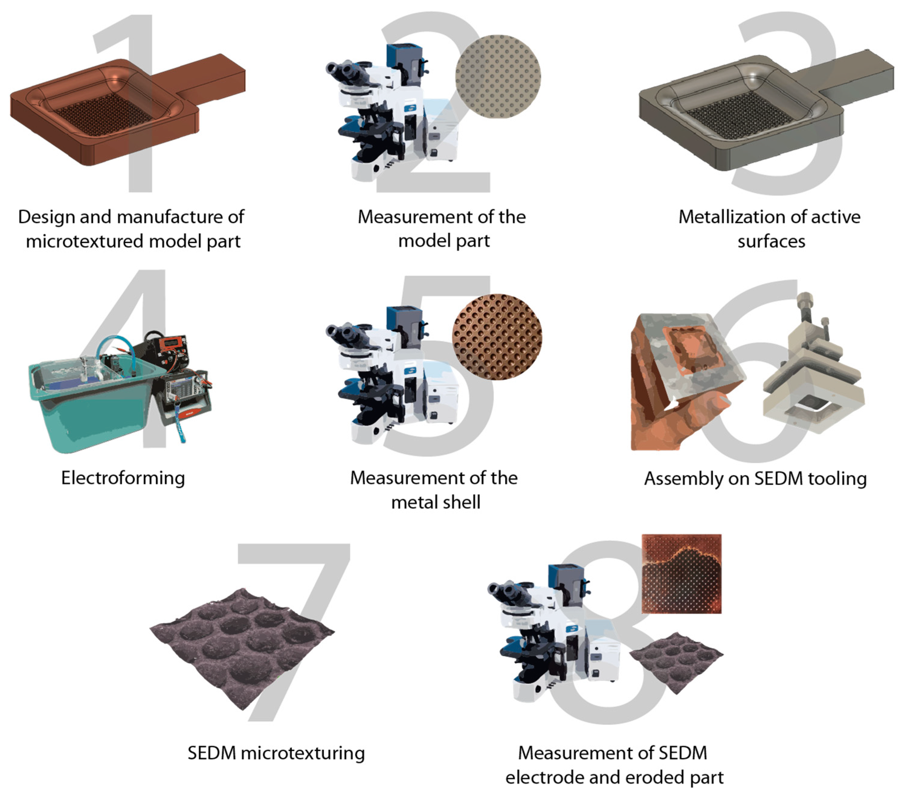
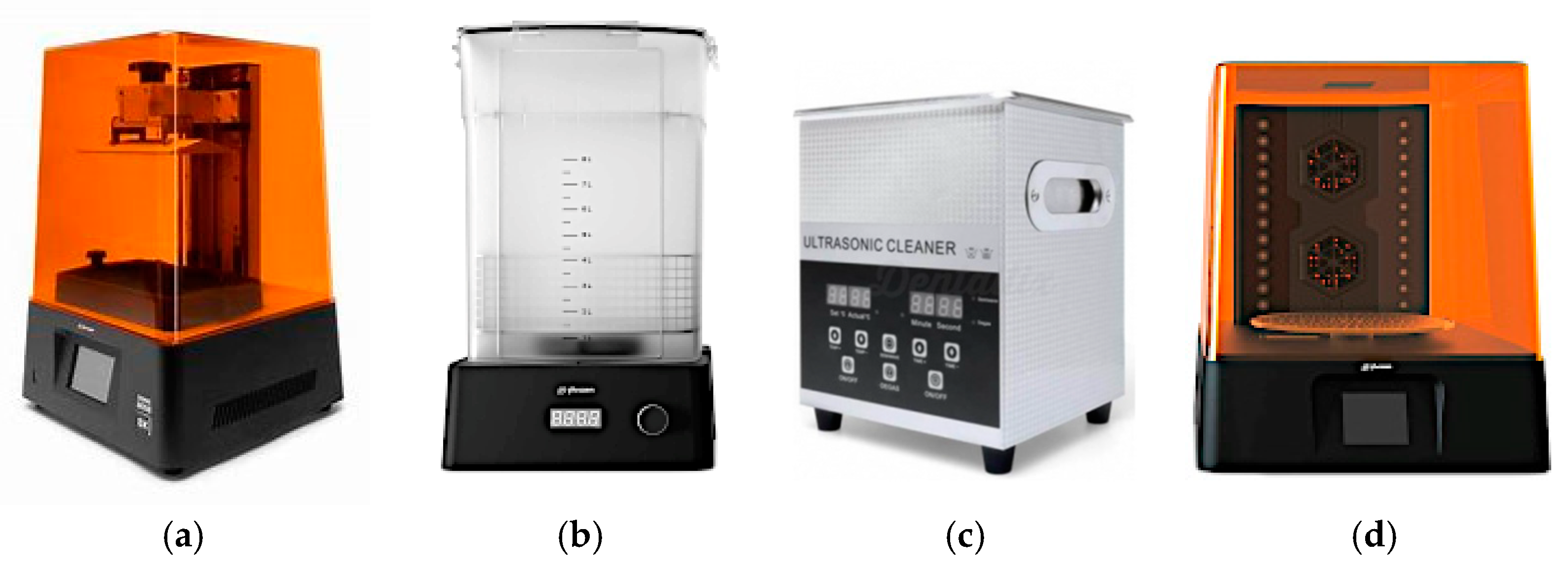
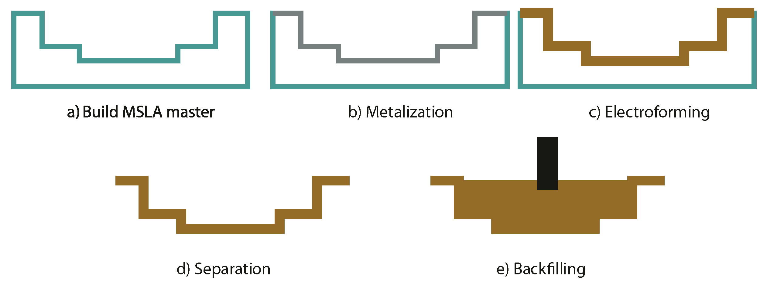
2.1. Design and Fabrication of Functional Models
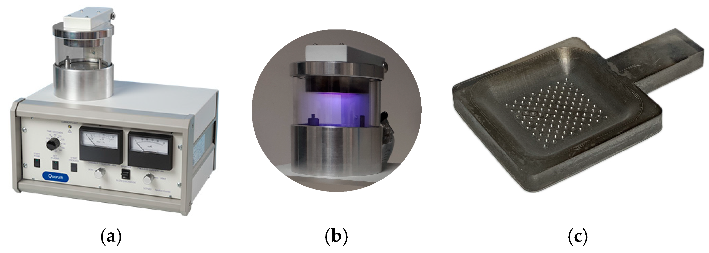
2.2. Sputtering
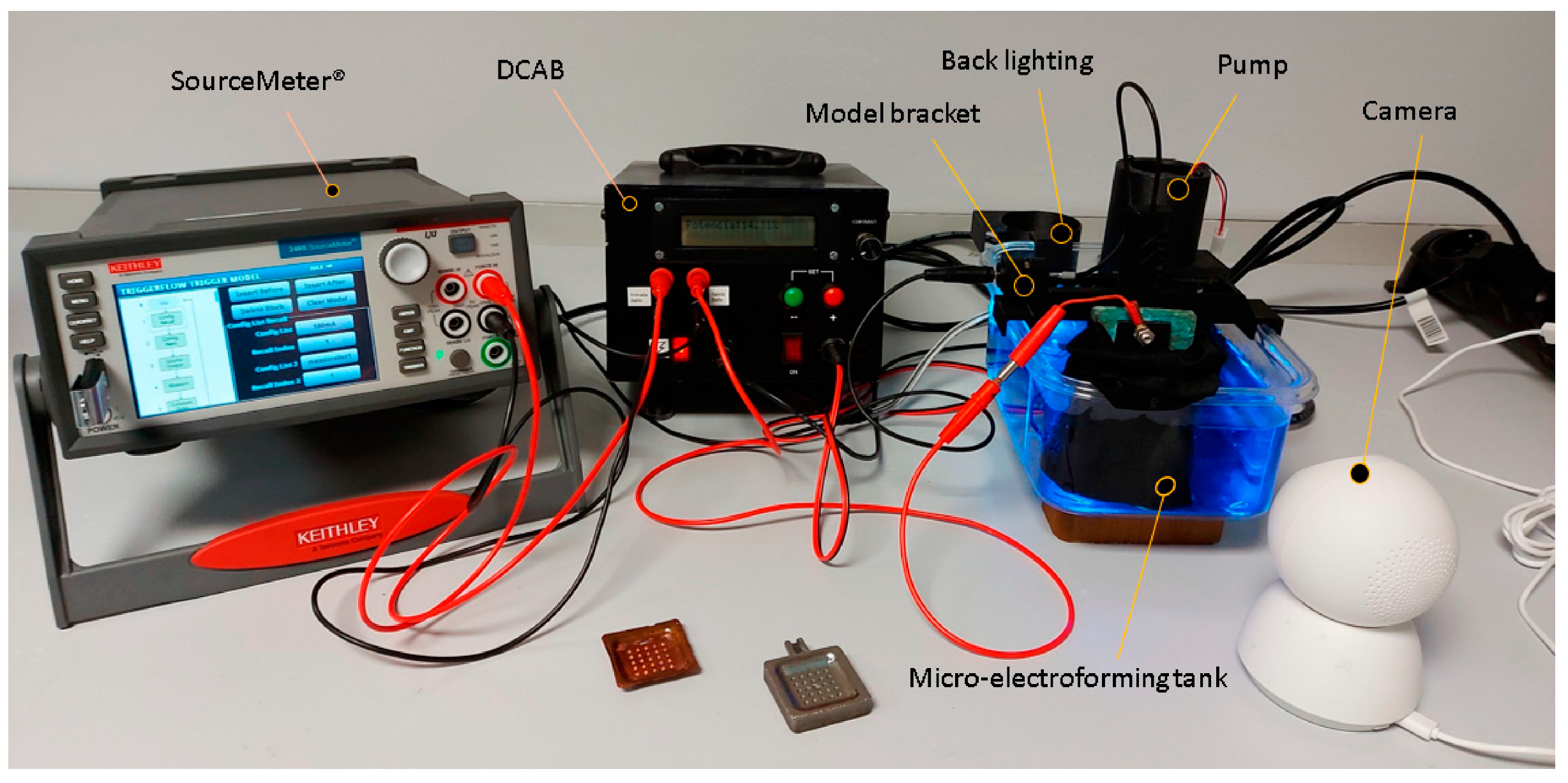
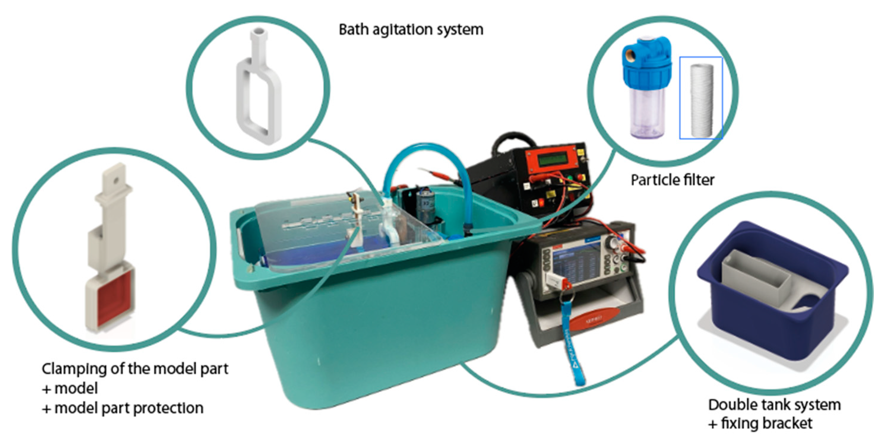
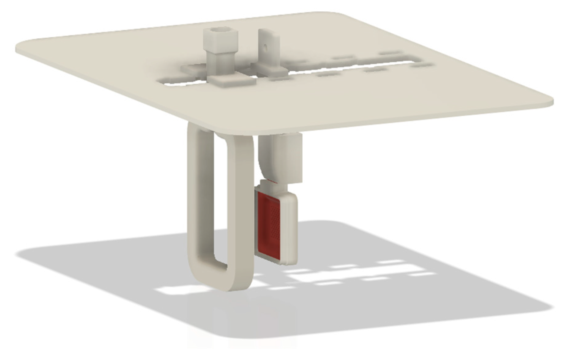
2.3. Electroforming
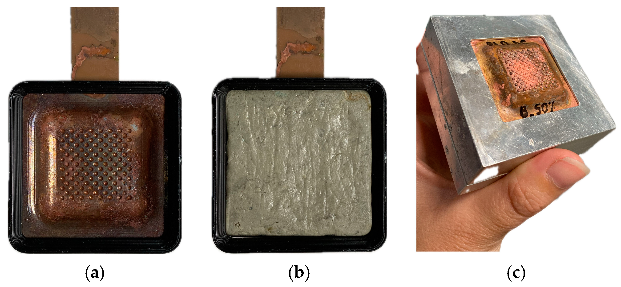
2.4. Use of the Shells as Texturized Tools for SEDM
2.5. Validation Method
3. Results
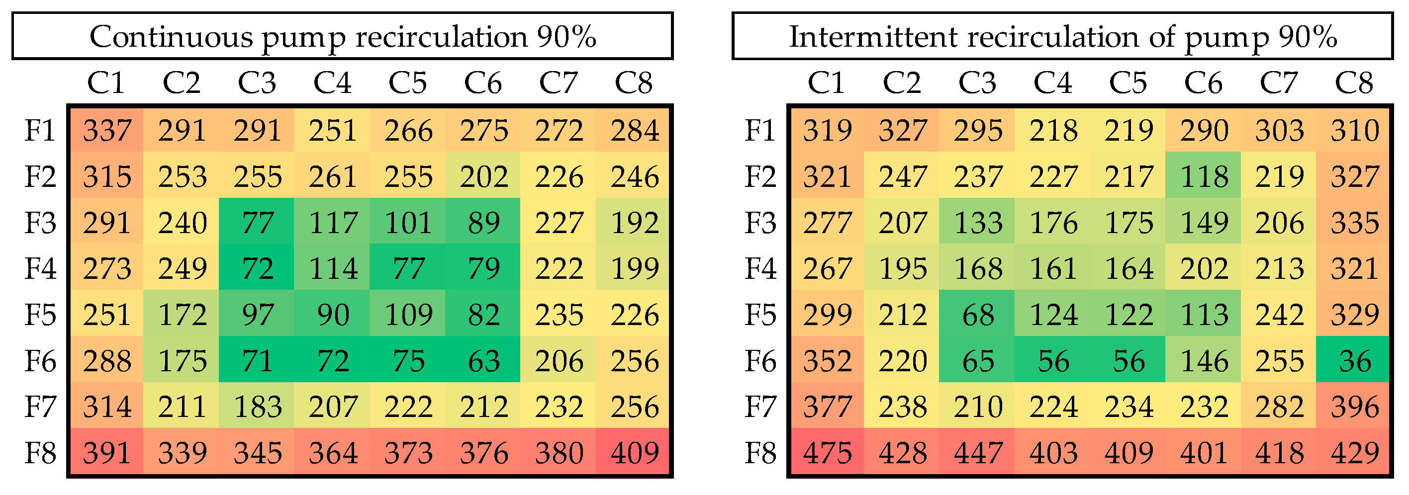
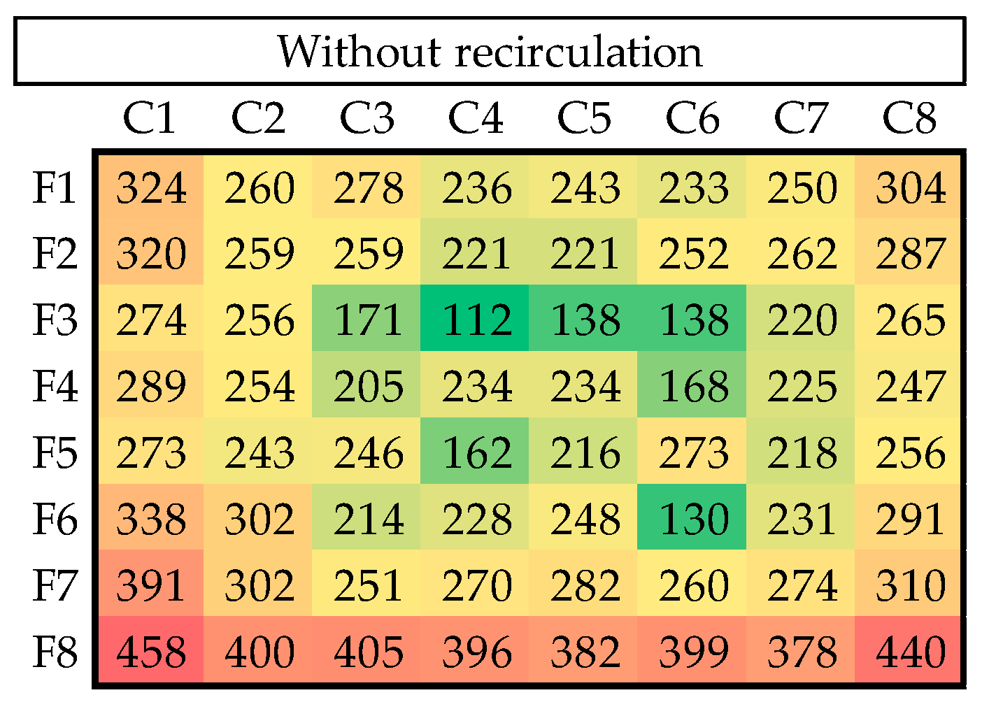
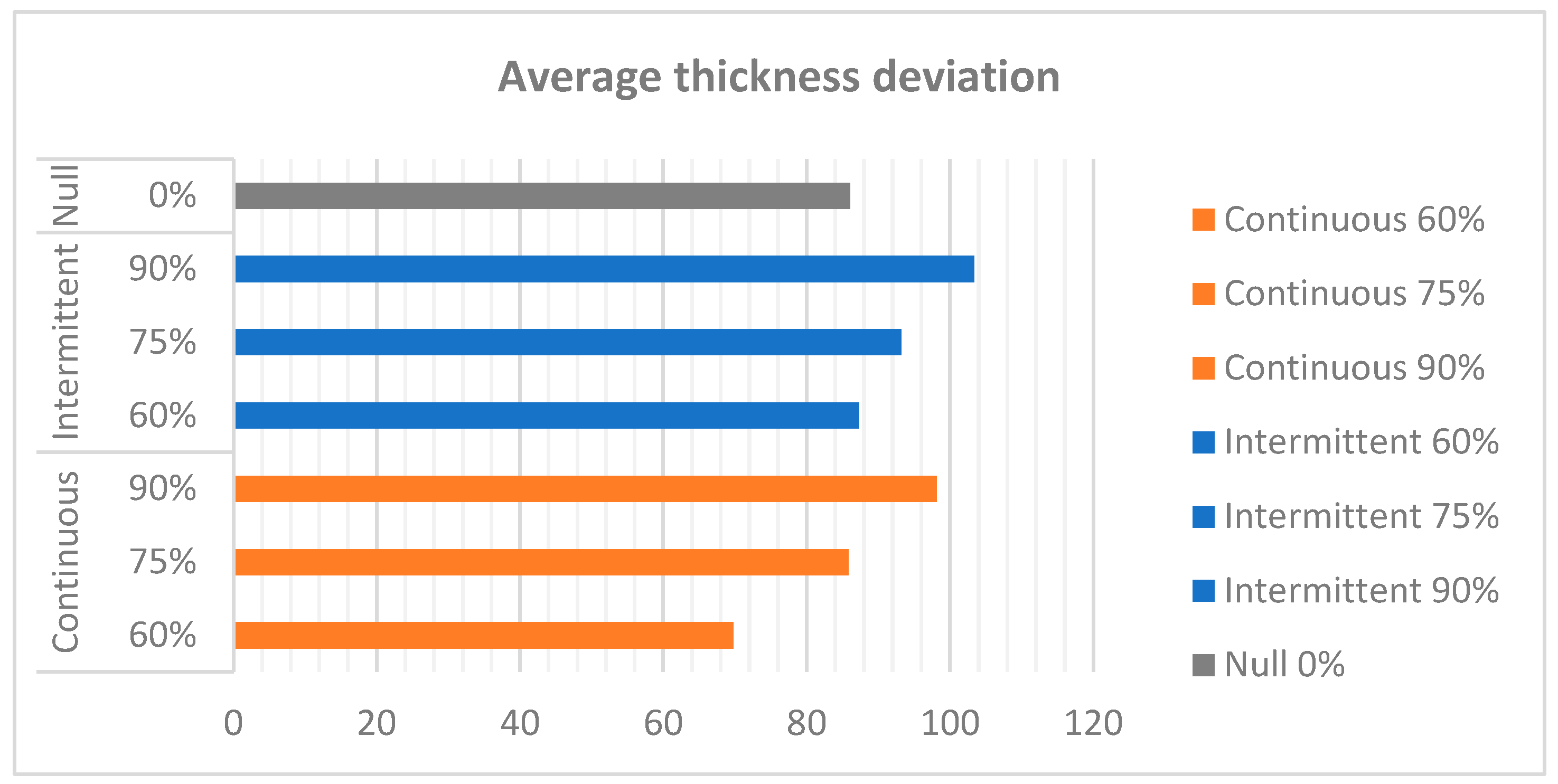
3.1. Analysis of the Impact of Pump Power on Recirculation
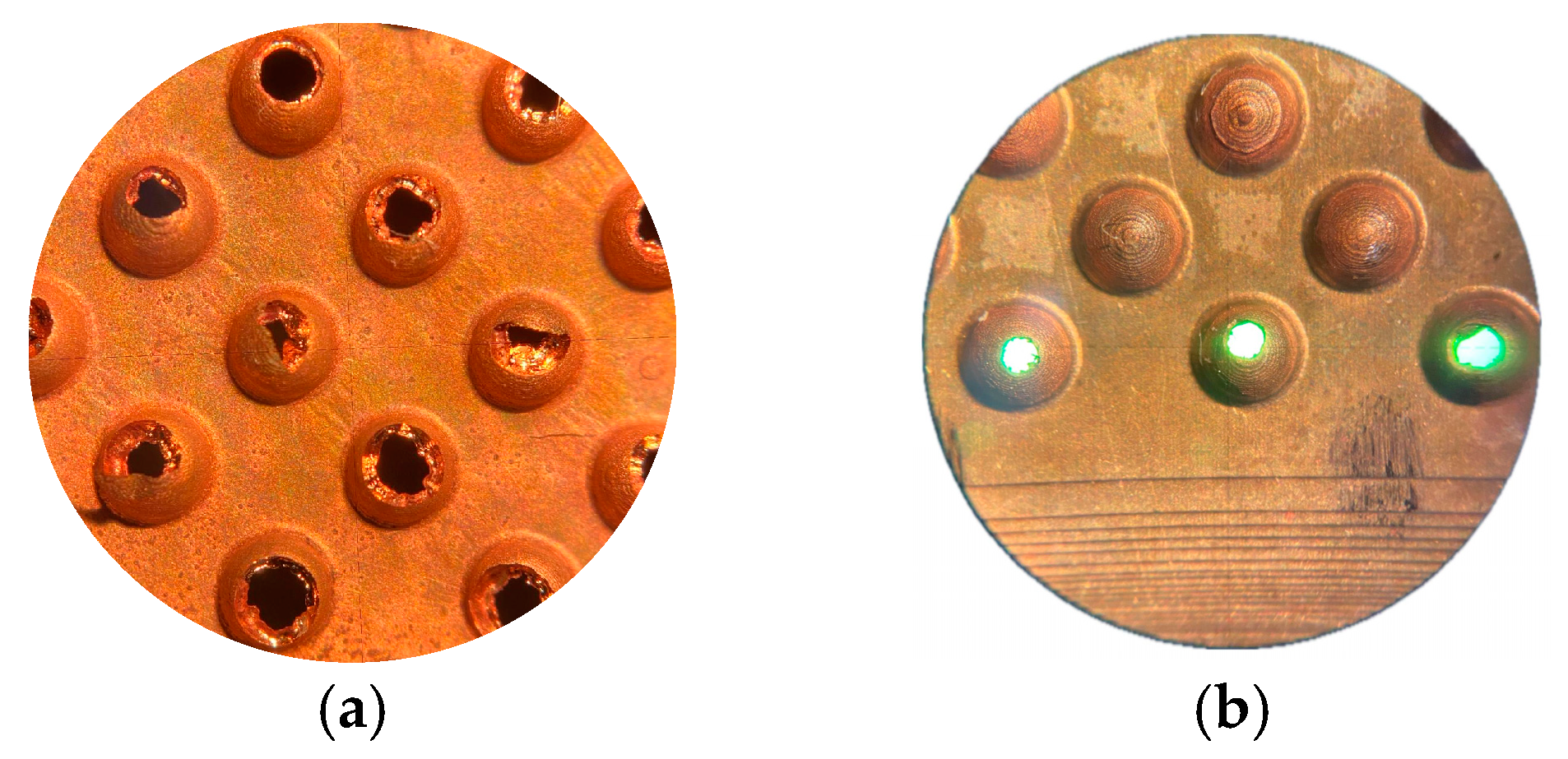
3.2. Electrode Wear Study
4. Discussion
5. Conclusions
Author Contributions
Funding
Institutional Review Board Statement
Informed Consent Statement
Data Availability Statement
Acknowledgments
Conflicts of Interest
Abbreviations
| MSLA | Masked Stereolithography |
| SEDM | Sink Electro-Discharge Machining |
| DCAB | Bath agitation control device |
References
- Szada-Borzyszkowska, M.; Kacalak, W.; Szada-Borzyszkowski, W.; Borkowski, P.J.; Laskowska, D.; Szafraniec, F. Topography of Textured Surfaces Using an Abrasive-Water Jet Technology. Arch. Civ. Mech. Eng. 2024, 24, 226. [Google Scholar] [CrossRef]
- Cheng, Z.; Du, M.; Lai, H.; Zhang, N.; Sun, K. From Petal Effect to Lotus Effect: A Facile Solution Immersion Process for the Fabrication of Super-Hydrophobic Surfaces with Controlled Adhesion. Nanoscale 2013, 5, 2776–2783. [Google Scholar] [CrossRef] [PubMed]
- Nosonovsky, M.; Bhushan, B. Multiscale Friction Mechanisms and Hierarchical Surfaces in Nano- and Bio-Tribology. Mater. Sci. Eng. R Rep. 2007, 58, 162–193. [Google Scholar] [CrossRef]
- Gachot, C.; Rosenkranz, A.; Hsu, S.M.; Costa, H.L. A Critical Assessment of Surface Texturing for Friction and Wear Improvement. Wear 2017, 372–373, 21–41. [Google Scholar] [CrossRef]
- Nasir, F.F.M.; Ghani, J.A.; Zamri, W.F.H.W.; Kasim, M.S. State-of-the-Art Surface Texturing and Methods for Tribological Performance. World Rev. Sci. Technol. Sustain. Dev. 2019, 15, 330. [Google Scholar] [CrossRef]
- Jithin, S.; Shetye, S.S.; Rodrigues, J.J.; Mhetre, K.S.; Mastud, S.A.; Joshi, S.S. Analysis of Electrical Discharge Texturing Using Different Electrode Materials. Adv. Mater. Process. Technol. 2018, 4, 466–479. [Google Scholar] [CrossRef]
- Ali, M.; Banu, A. Electrical Discharge Machining (EDM): A Review. Int. J. Eng. Mater. Manuf. 2016, 1, 3–10. [Google Scholar] [CrossRef]
- García-Martínez, E.; Miguel, V.; Mancebo, Á.; Martínez-Martínez, A. Determination of Cost-Effective Machining Strategies for Rough Pocket Milling of Aluminum by Computer-Aided Manufacturing. Adv. Sci. Technol. 2023, 132, 176–183. [Google Scholar] [CrossRef]
- Hazzan, K.E.; Pacella, M.; See, T.L. Laser Processing of Hard and Ultra-Hard Materials for Micro-Machining and Surface Engineering Applications. Micromachines 2021, 12, 895. [Google Scholar] [CrossRef]
- Yarlagadda, P.K.D.V.; Christodoulou, P.; Subramanian, V.S. Feasibility Studies on the Production of Electro-Discharge Machining Electrodes with Rapid Prototyping and the Electroforming Process. J. Mater. Process. Technol. 1999, 89–90, 231–237. [Google Scholar] [CrossRef]
- Álvarez, J. Estado del arte de las aplicaciones de texturizado y últimas tecnologías. Interempresas. 21 November 2016. Available online: https://www.interempresas.net/MetalMecanica/Articulos/165091-Estado-del-arte-de-las-aplicaciones-de-texturizado-y-ultimas-tecnologias.html (accessed on 11 March 2025).
- Pérez, M.; Carou, D.; Rubio, E.M.; Teti, R. Current Advances in Additive Manufacturing. Procedia CIRP 2020, 88, 439–444. [Google Scholar] [CrossRef]
- Hernández-Castellano, P.M.; Benítez-Vega, A.N.; Díaz-Padilla, N.; Ortega-García, F.; Socorro-Perdomo, P.; Marrero-Alemán, M.D.; Salguero, J. Design and Manufacture of Structured Surfaces by Electroforming. Procedia Manuf. 2017, 13, 402–409. [Google Scholar] [CrossRef]
- Hernández-Pérez, M.; Hernández-Castellano, P.M.; Sánchez-Morales, C.J.; Marrero-Alemán, M.D.; Martinez, J.M.V. Metrological Assessment of Microtextured EDM Electrodes Generated by Additive Manufacturing and Electroforming. Key Eng. Mater. 2023, 960, 47–56. [Google Scholar] [CrossRef]
- Muhye, A. Galvanoplastia: Procesos, Aplicaciones y Ejemplos. Lifeder. Available online: https://www.lifeder.com/galvanoplastia/ (accessed on 10 January 2021).
- Akgün, M. Performance Analysis of Electrode Materials in Electro Discharge Machining of Monel K-500. Surf. Topogr. Metrol. Prop. 2022, 10, 035026. [Google Scholar] [CrossRef]
- Li, Z.; Bai, J.; Tang, J. Micro-EDM Method to Fabricate Three-Dimensional Surface Textures Used as SERS-Active Substrate. Appl. Surf. Sci. 2018, 458, 810–818. [Google Scholar] [CrossRef]
- Hsu, C.Y.; Chen, D.Y.; Lai, M.Y.; Tzou, G.J. EDM Electrode Manufacturing Using RP Combining Electroless Plating with Electroforming. Int. J. Adv. Manuf. Technol. 2008, 38, 915–924. [Google Scholar] [CrossRef]
- Sánchez, C.J.; Hernández, P.M.; Martínez, M.D.; Marrero, M.D.; Salguero, J. Combined Manufacturing Process of Copper Electrodes for Micro Texturing Applications (AMSME). Materials 2021, 14, 2497. [Google Scholar] [CrossRef]
- Alicona, B. InfiniteFocus G6. Fast Measurements for Smooth Surfaces & Offline CAD Planning. Available online: https://www.alicona.com/en/products/infinitefocus/ (accessed on 9 June 2022).
- Permadi, B.; Asroni, A.; Budiyanto, E. Proses elektroplating nikel dengan variasi jarak anoda katoda dan tegangan listrik pada baja ST-41. Turbo J. Program Studi Tek. Mesin 2020, 8, 226–230. [Google Scholar] [CrossRef]
- García, O. Efecto de diferentes parámetros sobre la calidad de las electroformas de níquel Desarrollo y validación de dispositivo para mejorar la uniformidad de espesor. Doctoral Dissertation, Universidad de Las Palmas de Gran Canaria (ULPGC), Las Palmas de Gran Canaria, Spain, 2014. [Google Scholar]
- Yang, G.; Deng, D.; Zhang, Y.; Zhu, Q.; Cai, J. Numerical Optimization of Electrodeposition Thickness Uniformity with Respect to the Layout of Anode and Cathode. Electrocatalysis 2021, 12, 478–488. [Google Scholar] [CrossRef]
- Aisyah, I.S.; Susilo, R.R.; Murjito, M. The Effect of Distance Variation on Electroplating Process of Decorative Nickel-Chrome on the Microstructure, Thickness and Weight of Plating on A36 Steel. AIP Conf. Proc. 2022, 2453, 020013. [Google Scholar] [CrossRef]
- Sun, H.; Wang, X. Numerical Simulation of Nickel Electroforming Process Influenced by Flow Field. In Proceedings of the 10th IEEE International Conference on Nano/Micro Engineered and Molecular Systems, Xi’an, China, 7–11 April 2015; pp. 502–506. [Google Scholar]
- McGeough, J.A.; Rasmussen, H. Analysis of Electroforming with Direct Current. J. Mech. Eng. Sci. 1977, 19, 163–166. [Google Scholar] [CrossRef]
- Chalupa, A.; Warner, J.; Martin, J. Computational Study of Chemical Uniformity Impacts on Electrodeposition. IEEE Trans. Semicond. Manuf. 2024, 37, 238–243. [Google Scholar] [CrossRef]


| Stages | Intensity | Time |
|---|---|---|
| 1 | 100 mA | 1 h |
| 2 | 250 mA | 30 min |
| 3 | 500 mA | 1 h |
| 4 | 750 mA | 1 h |
| 5 | 1 A | 1 h |
| Experiment | Repetition | Pump Power | Recirculation Type |
|---|---|---|---|
| 1 | 3 | 60% | Continuous |
| 2 | 3 | 75% | Continuous |
| 3 | 3 | 90% | Continuous |
| 4 | 3 | 60% | Intermittent |
| 5 | 3 | 75% | Intermittent |
| 6 | 3 | 90% | Intermittent |
| 7 | 3 | 0% | Null |
Disclaimer/Publisher’s Note: The statements, opinions and data contained in all publications are solely those of the individual author(s) and contributor(s) and not of MDPI and/or the editor(s). MDPI and/or the editor(s) disclaim responsibility for any injury to people or property resulting from any ideas, methods, instructions or products referred to in the content. |
© 2025 by the authors. Licensee MDPI, Basel, Switzerland. This article is an open access article distributed under the terms and conditions of the Creative Commons Attribution (CC BY) license (https://creativecommons.org/licenses/by/4.0/).
Share and Cite
Hernández-Pérez, M.; Hernández-Castellano, P.M.; Salguero-Gómez, J.; Sánchez-Morales, C.J. Improved Design of Electroforming Equipment for the Manufacture of Sinker Electrical Discharge Machining Electrodes with Microtextured Surfaces. Materials 2025, 18, 1972. https://doi.org/10.3390/ma18091972
Hernández-Pérez M, Hernández-Castellano PM, Salguero-Gómez J, Sánchez-Morales CJ. Improved Design of Electroforming Equipment for the Manufacture of Sinker Electrical Discharge Machining Electrodes with Microtextured Surfaces. Materials. 2025; 18(9):1972. https://doi.org/10.3390/ma18091972
Chicago/Turabian StyleHernández-Pérez, Mariana, Pedro M. Hernández-Castellano, Jorge Salguero-Gómez, and Carlos J. Sánchez-Morales. 2025. "Improved Design of Electroforming Equipment for the Manufacture of Sinker Electrical Discharge Machining Electrodes with Microtextured Surfaces" Materials 18, no. 9: 1972. https://doi.org/10.3390/ma18091972
APA StyleHernández-Pérez, M., Hernández-Castellano, P. M., Salguero-Gómez, J., & Sánchez-Morales, C. J. (2025). Improved Design of Electroforming Equipment for the Manufacture of Sinker Electrical Discharge Machining Electrodes with Microtextured Surfaces. Materials, 18(9), 1972. https://doi.org/10.3390/ma18091972