
Study on the Seismic Performance of Steel Tube-Reinforced Concrete Columns After Fire on One Side


Abstract
:1. Introduction
2. Establishment of Finite Element Model
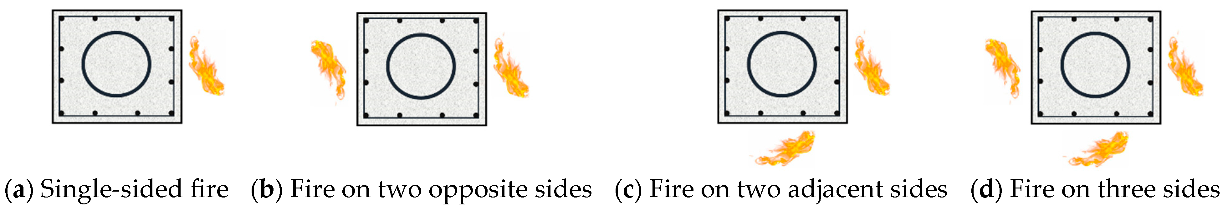
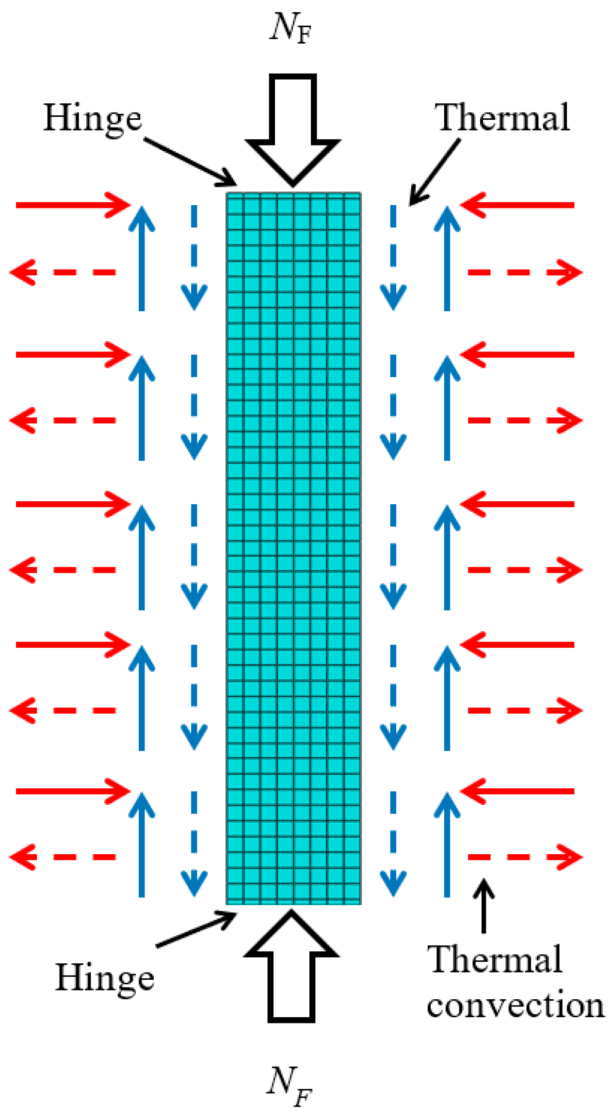
2.1. Stress Analysis Model
2.2. Modeling Method
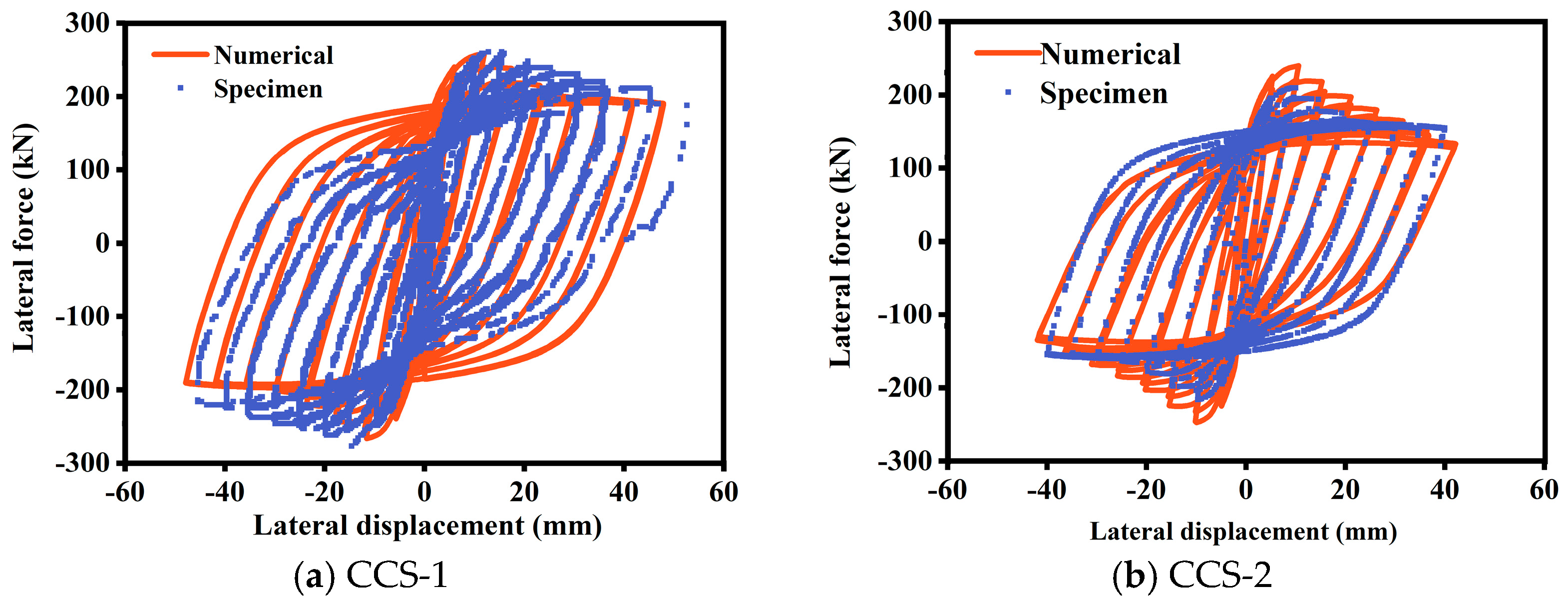
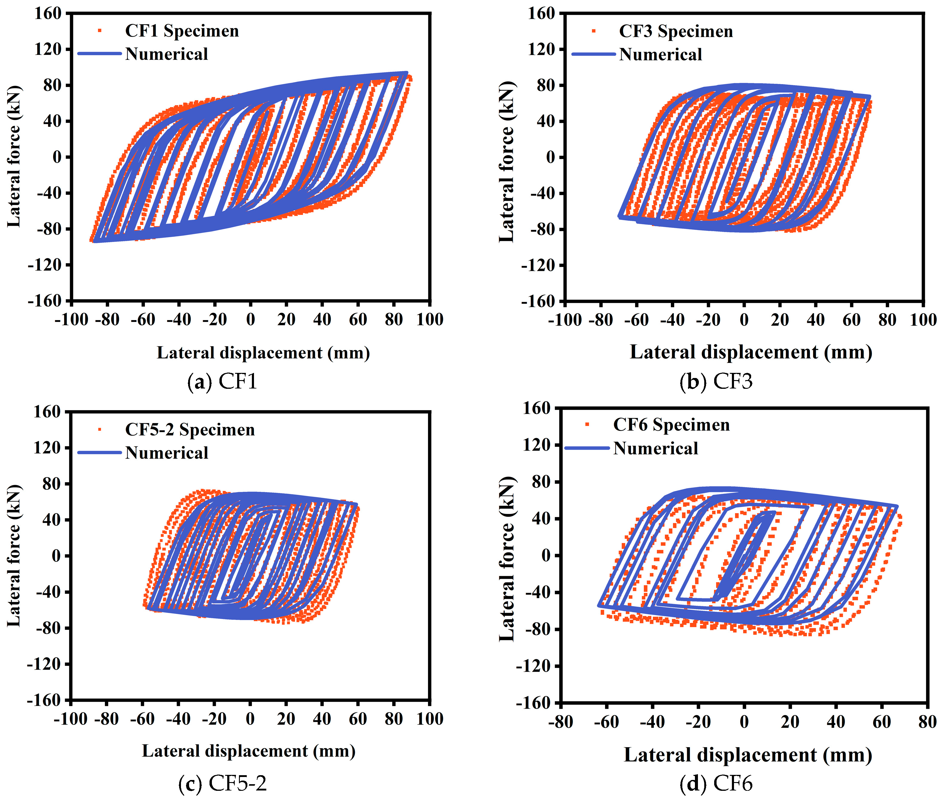
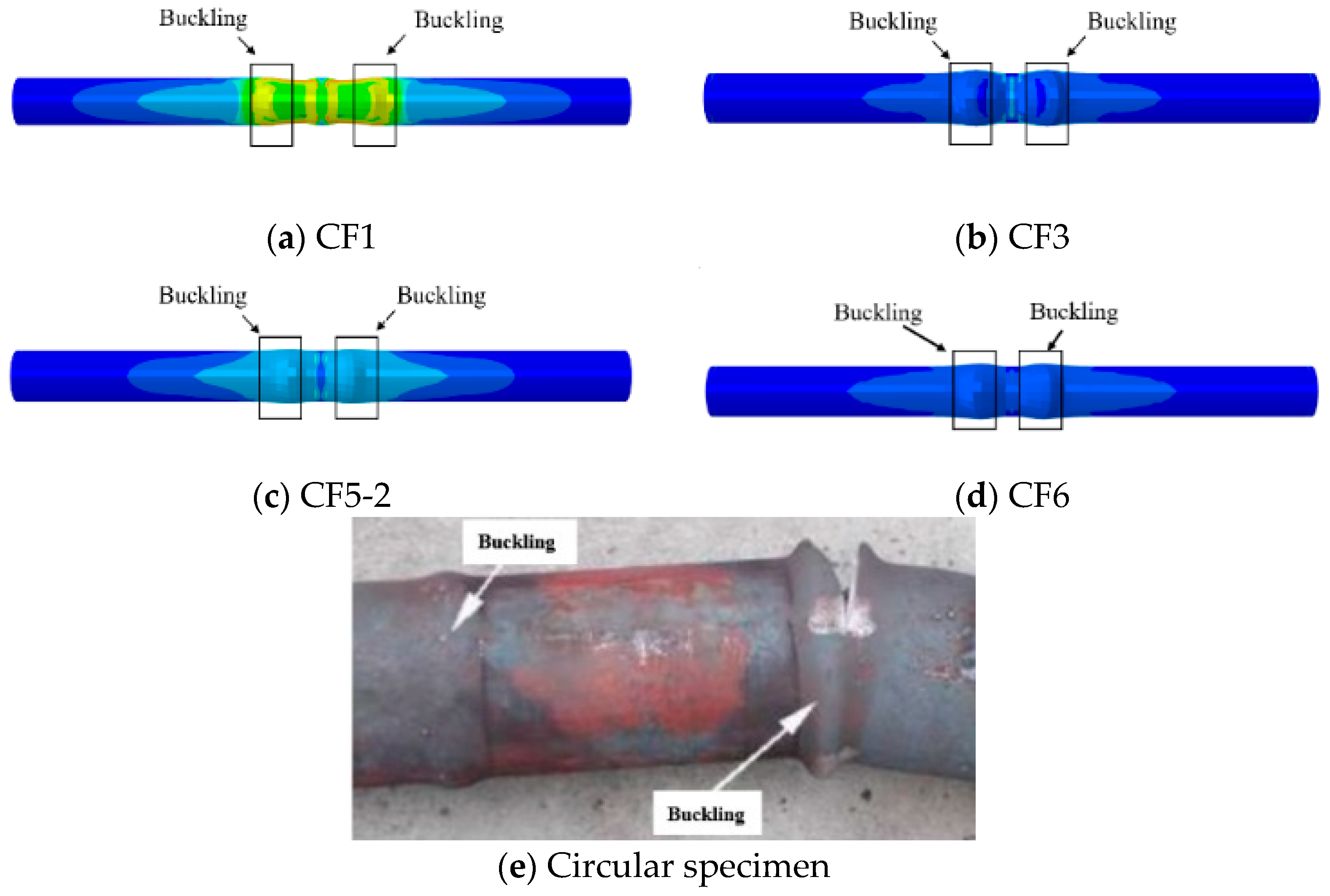
2.3. Verification of Finite Element Model
3. Seismic Mechanism Analysis After Fire on Single Side
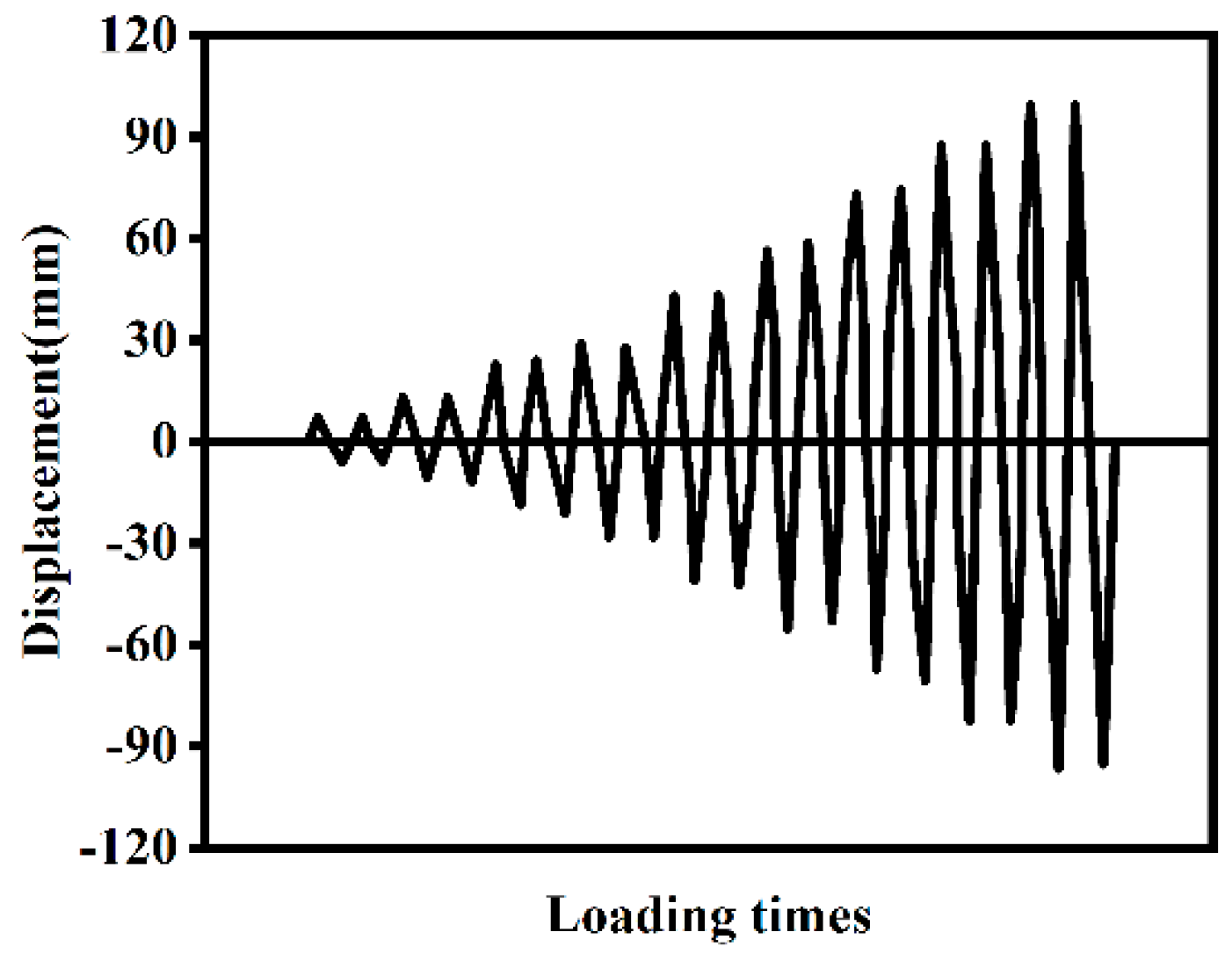
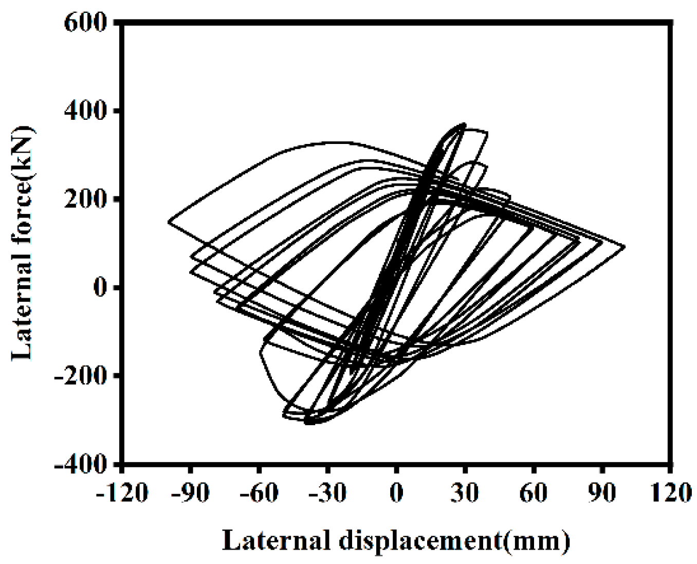
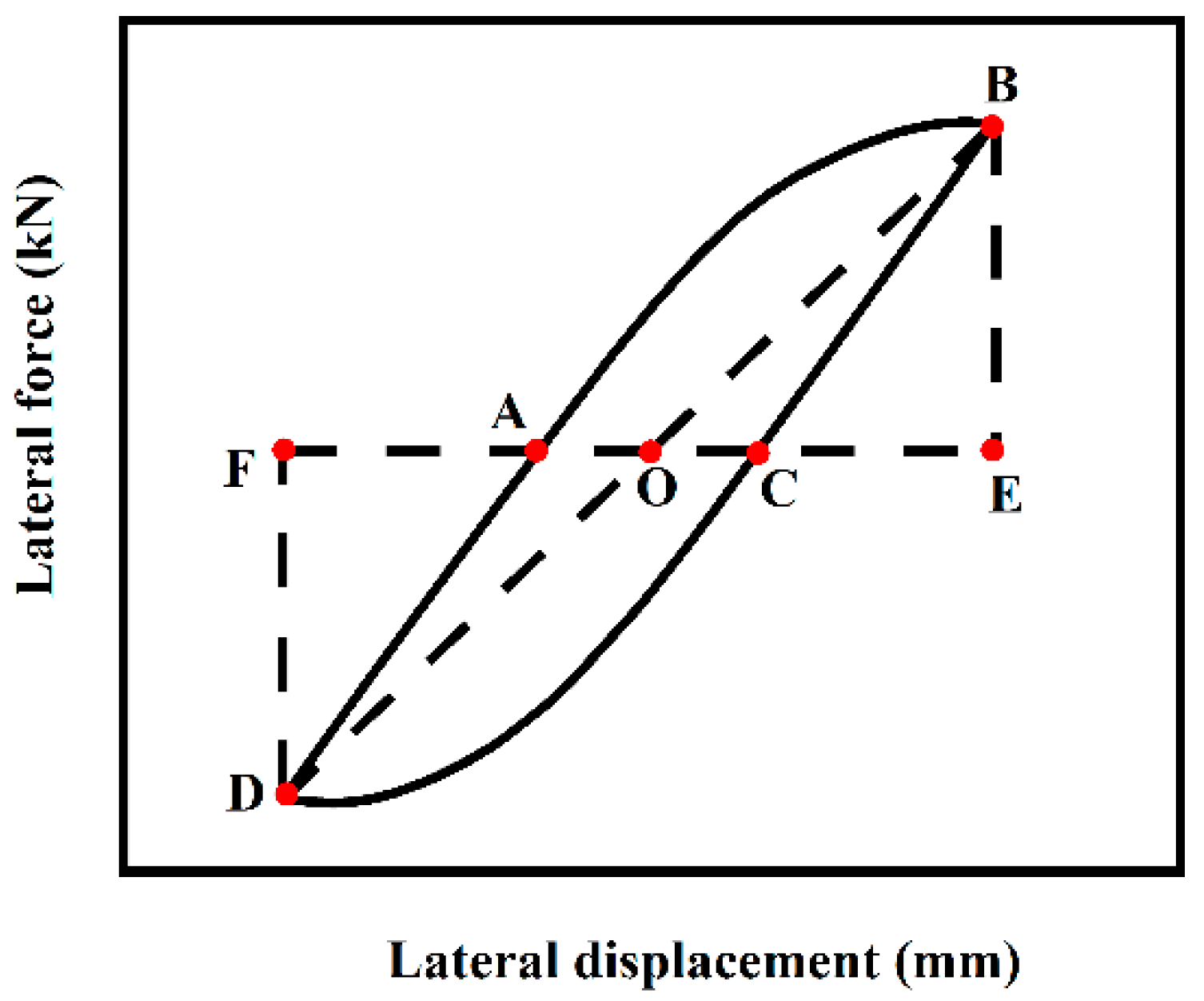
3.1. Hysteresis Curve
- (1)
- O-A Stage: The load-displacement curve exhibits a linear relationship, indicating that the component is in the elastic stage.
- (2)
- A-B Stage: After reaching point A, the component begins to enter the elastoplastic stage as the horizontal displacement increases. The stiffness of the composite column also starts to decline.
- (3)
- B-C Stage: Unloading begins at point B. During this process, the unloading stiffness remains similar to the stiffness in the elastic stage. Part of the cross-section transitions from tension to compression, with the tension zone gradually decreasing and the compression zone expanding. When the external load is reduced to zero, residual strain occurs due to stiffness degradation and residual compressive stress within the composite column.
- (4)
- C-D Stage: After point C, reverse loading begins. The stiffness remains unchanged, but the compression zone of the cross-section continues to expand.
- (5)
- D-E Stage: The composite column enters the elastoplastic stage during reverse loading. As the horizontal displacement increases, the area of the compression zone in the cross-section expands, and the outer reinforced concrete experiences plastic damage, leading to stiffness degradation.
- (6)
- E-F Stage: With repeated unloading and loading cycles, damage accumulates in the outer reinforced concrete, resulting in continuous reductions in strength and stiffness.
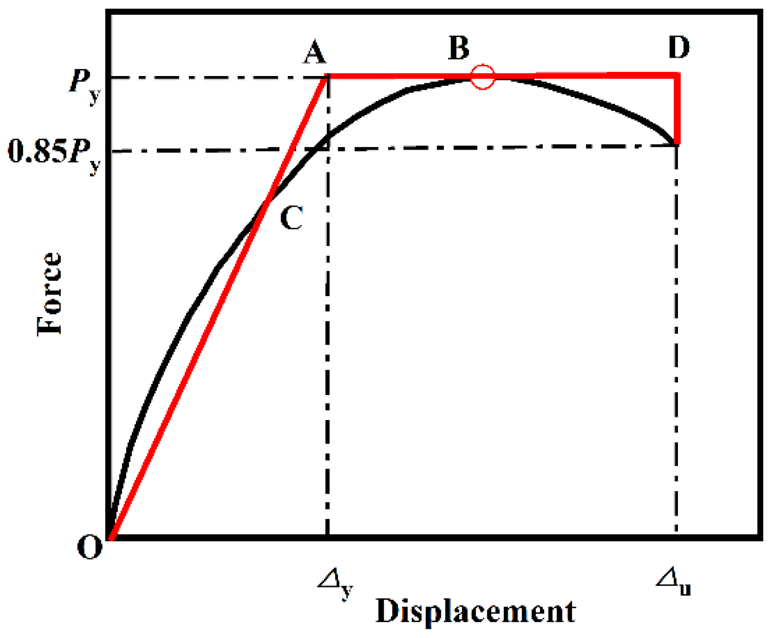
3.2. Skeleton Curve
3.3. Ductility
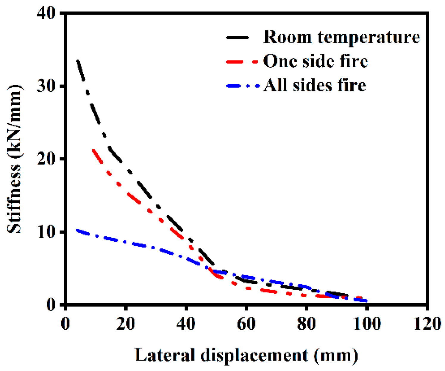
3.4. Stiffness Degradation
- (1)
- The secant stiffness of components under different fire exposure conditions, including unexposed components, decreases as lateral displacement increases. This is primarily due to concrete cracking and the transition into the elastoplastic deformation stage at larger lateral displacements, which reduces the component’s ability to resist deformation.
- (2)
- As the number of fire-exposed surfaces increases, both the initial stiffness and the secant stiffness at the same lateral displacement decrease. Compared to unexposed components, the initial stiffness of components after single-side fire exposure decreases by 24.69%, while that of components exposed to fire on all sides decreases by 69.37%. This reduction is attributed to the degradation of material properties in both steel and concrete after a fire. Specifically, the elastic modulus of steel cannot fully recover to its pre-fire state after cooling, leading to a reduction in the initial stiffness of the components.
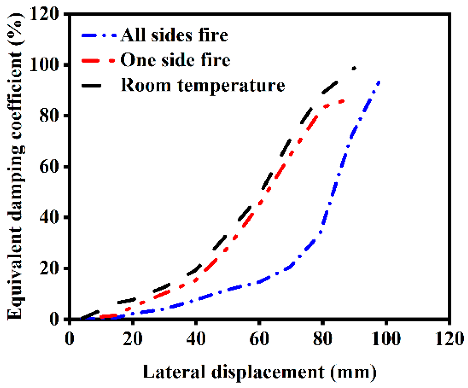
3.5. Energy Dissipation Capacity
- (1)
- In the initial stage of cyclic loading, the structures are primarily in the elastic stage, with small hysteresis loop areas and minimal energy dissipation.
- (2)
- Unexposed components exhibit a higher bearing capacity and relatively fuller hysteresis loops, indicating a superior energy dissipation capacity.
- (3)
- As the number of fire-exposed surfaces increases, the energy dissipation capacity of the components decreases. The energy dissipation capacity of components exposed to fire on one side is slightly reduced compared to unexposed components, while that of components exposed to fire on all sides is significantly reduced. However, when the loading displacement exceeds 80 mm, components exposed to fire on all sides enter the plastic deformation stage under cyclic loading, leading to a notable enhancement in energy dissipation capacity.
4. Parameter Analysis of Seismic Performance
4.1. Ductility
4.1.1. Influence of Heating Time on Ductility
4.1.2. Influence of Slenderness Ratio on Ductility
4.1.3. Influence of Section Size on Ductility
4.1.4. Influence of Core Area Ratio on Ductility
4.1.5. Influence of External Concrete Strength on Ductility
4.1.6. Influence of Reinforcement Ratio on Ductility
4.1.7. Influence of Load Ratio on Ductility
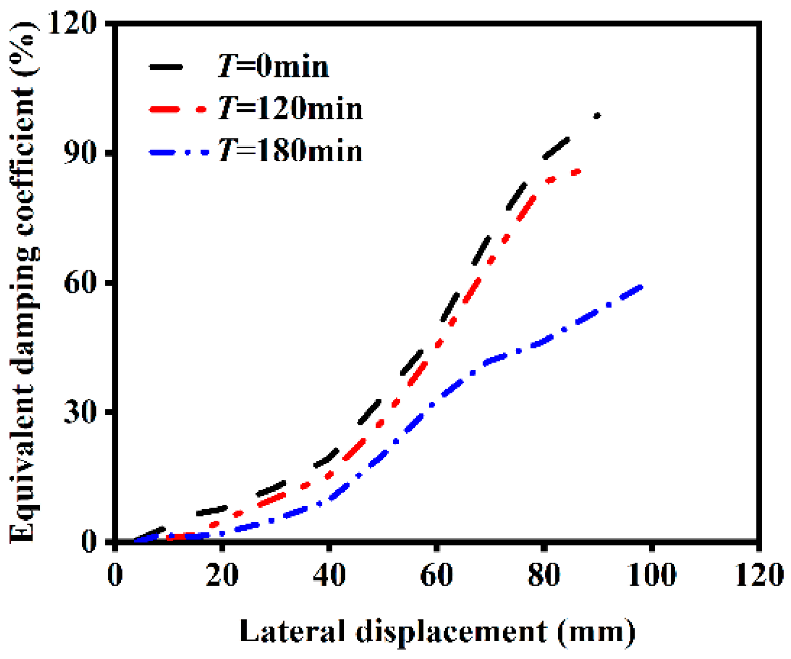
4.2. Energy Dissipation Capacity
4.2.1. Influence of Heating Time
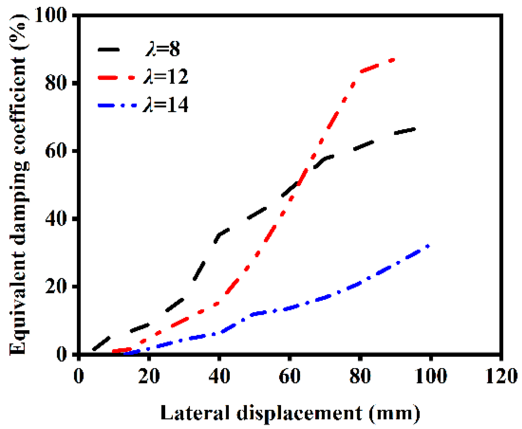
4.2.2. Influence of Slenderness Ratio
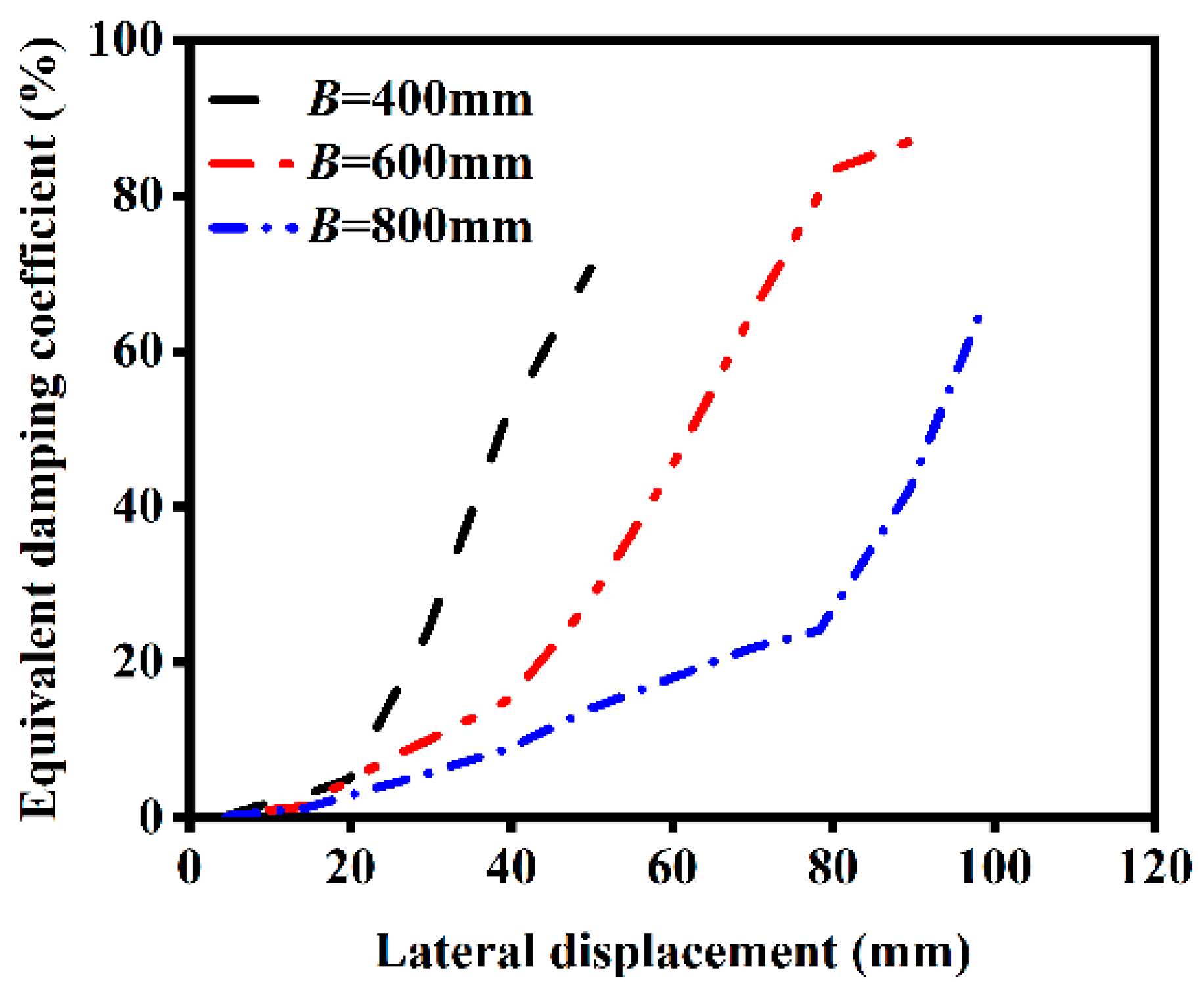
4.2.3. Influence of Section Size
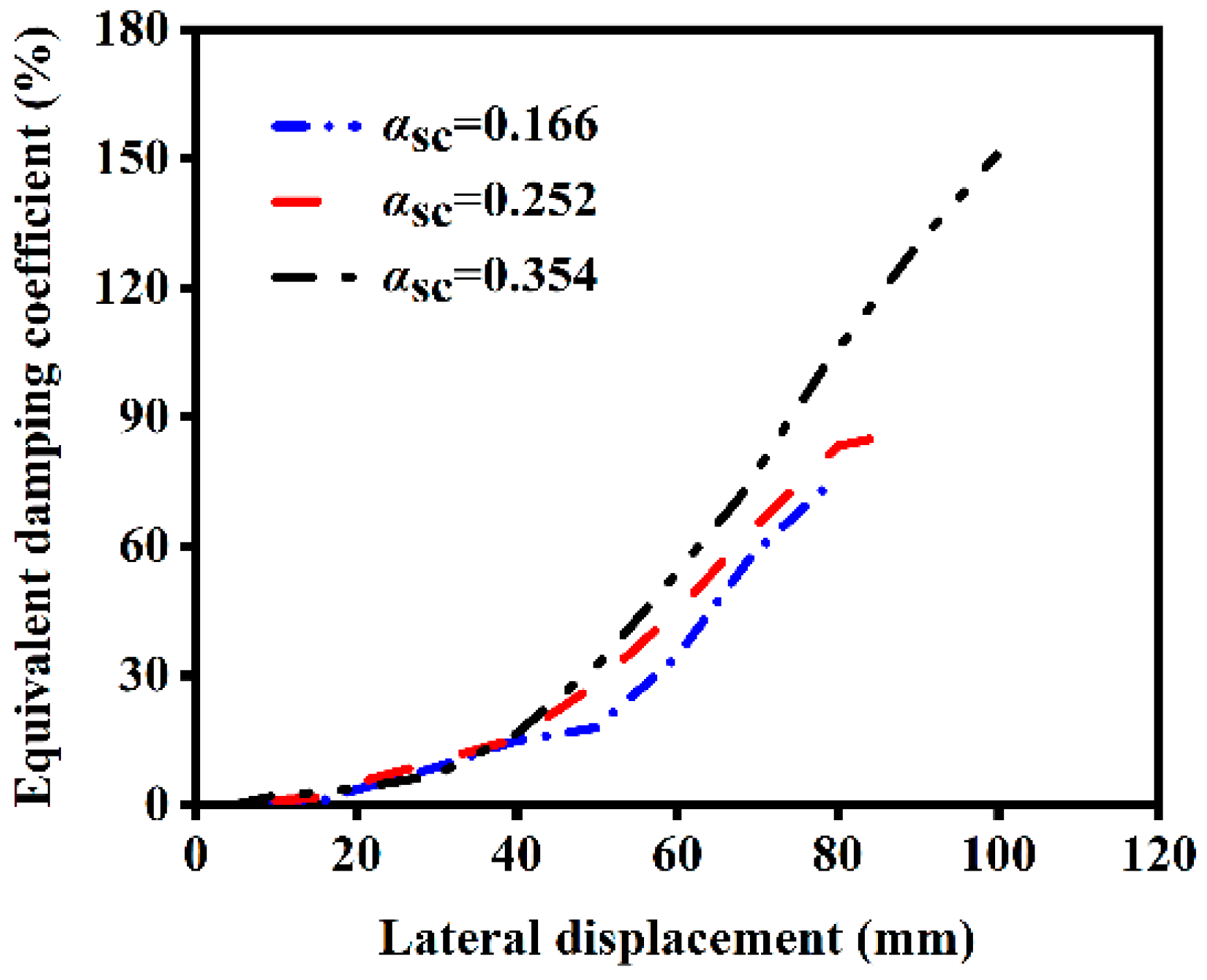
4.2.4. Influence of Core Area Ratio
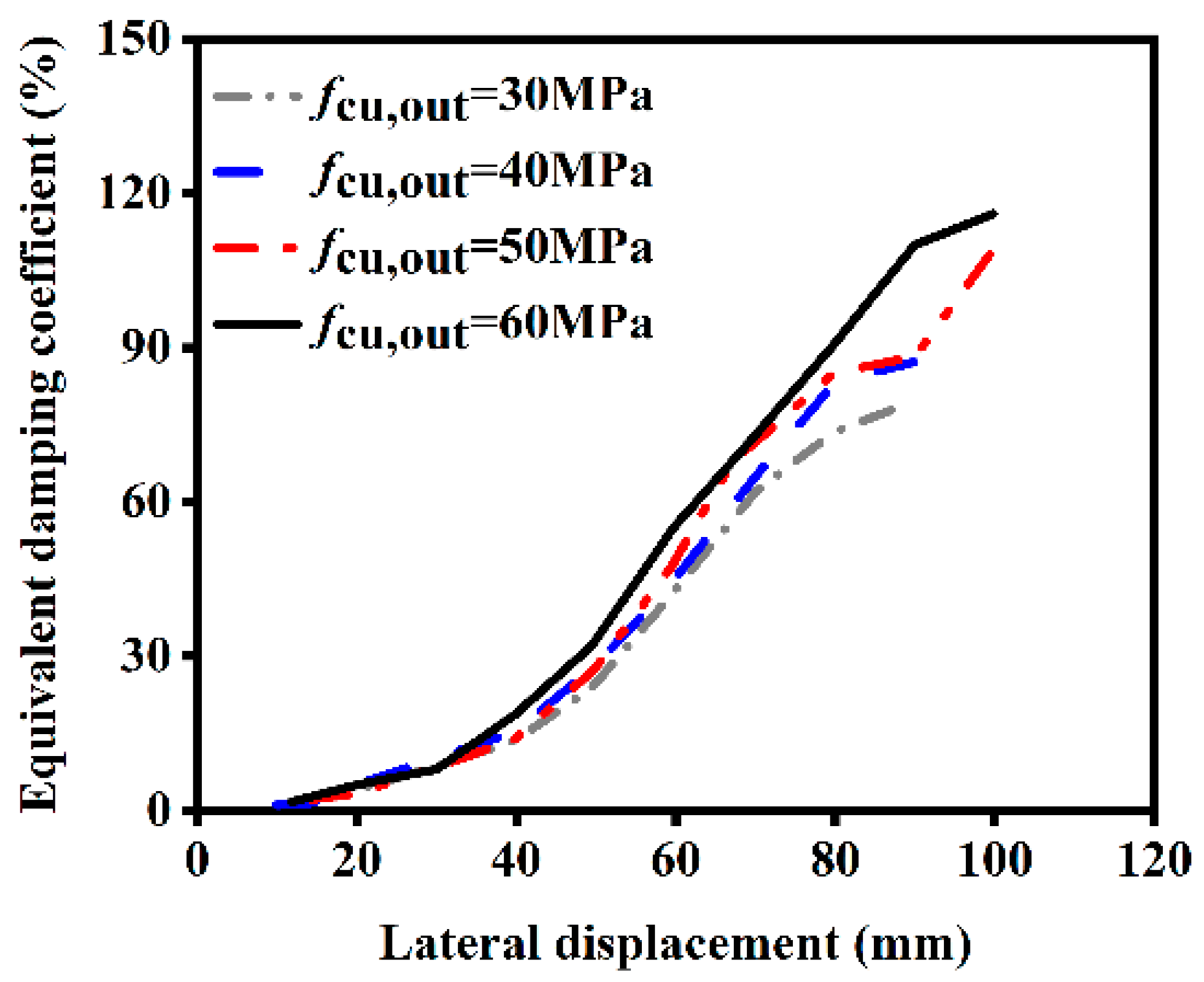
4.2.5. Influence of External Concrete Strength
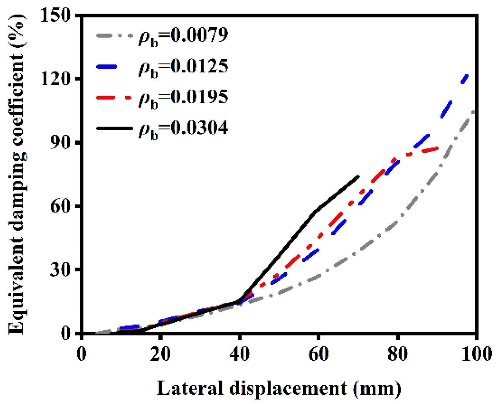
4.2.6. Influence of Reinforcement Ratio
4.2.7. Influence of Load Ratio
5. Conclusions
- The ductility of ST-RC columns exposed to fire on one side will be weakened, and the ductility coefficient will be decreased by 5.62% compared with that of non-fire members, while the ductility coefficient of ST-RC columns exposed to fire on all sides will be decreased by 11.24% compared with that of non-fire members. It can be seen that the ductility of single-sided fire-exposed components is not significant, while the ductility of four-sided fire-exposed components is more significant, about twice that of single-sided fire-exposed components.
- The initial stiffness of members exposed to fire on one side decreased by 24.69% compared with that of non-fire members, while the stiffness of members exposed to fire on all sides decreased by 69.37% compared with that of non-fire members. It can be seen that the greater the fire exposure, the smaller the initial stiffness, because the elastic modulus of the steel cannot be restored to its initial state after the fire.
- The energy dissipation capacity of the component will decay after unilateral fire, and it will continue to increase during the the loading process. When the component enters the plastic deformation stage, the energy dissipation capacity will suddenly increase.
- The heating time, slenderness ratio, section size, core area ratio, and reinforcement ratio are the main factors that affect the ductility of ST-RC columns after fire on one side. The heating time, slenderness ratio, section size, core area ratio, external concrete strength, reinforcement ratio, and load ratio are the main factors that affect the energy dissipation capacity of ST-RC columns after fire on one side.
Author Contributions
Funding
Institutional Review Board Statement
Informed Consent Statement
Data Availability Statement
Conflicts of Interest
References
- Xu, L.; Wang, M.T.; Bao, Y.H.; Wang, W.D. Numerical analysis on structural behaviors of concrete filled steel tube reinforced concrete (CFSTRC) columns subjected to 3-side fire. Int. J. Steel. Struct. 2017, 17, 1515–1528. [Google Scholar] [CrossRef]
- Xu, L.; Liu, Y.B. Concrete Filled Steel Tube Reinforced Concrete (CFSTRC) Columns Subjected to ISO-834 Standard Fire: Experiment. Adv. Struct. Eng. 2013, 16, 1263–1282. [Google Scholar] [CrossRef]
- Zhou, K.; Han, L.H. Experimental performance of concrete-encased CFST columns subjected to full-range fire including heating and cooling. Eng. Struct. 2018, 165, 331–489. [Google Scholar] [CrossRef]
- Simoncelli, M.; Zucca, M.; Stochino, F. Fire Resistance of Steel Rack Frames: Assessment, Reinforcement and Collapse Mitigation Strategies. Fire Technol. 2024, 1664, 1–23. [Google Scholar] [CrossRef]
- Qian, J.R.; Kang, H.Z. Experimental study on seismic behavior of high-strength concrete-filled steel tube composite columns. J. Build. Struct. 2009, 30, 85–93. [Google Scholar] [CrossRef]
- Li, H.; Wang, Z.Y.; Wu, B. Experimental research on mechanism and seismic performance of laminate column with steel tube filled with high-strength concrete. Earthq. Eng. Eng. Dyn. 1999, 19, 27–33. [Google Scholar]
- Moehle, J.P. Seismic analysis, design, and review for tall buildings. Struct. Design Tall Spec. Build. 2006, 15, 495–513. [Google Scholar] [CrossRef]
- Moghaddam, H.; Hajirasouliha, I. Optimum strength distribution for seismic design of tall buildings. Struct. Design Tall Spec. Build. 2008, 17, 331–349. [Google Scholar] [CrossRef]
- Bao, Y.H.; Yang, L. Study on Mechanical Performance of Square Steel Tube-Reinforced Concrete (ST-RC) Columns Subjected to Three Sides Fire. Pro. Steel. Build. Struct. 2023, 25, 43–53+67. [Google Scholar] [CrossRef]
- Yang, L.; Bao, Y.H. Study on mechanical performance of square steel tube-reinforced concrete (ST-RC) columns subjected to one-side fire. Build. Sci. 2023, 39, 43–53. [Google Scholar] [CrossRef]
- Wang, G.; Bao, Y.; Yang, L.; Yu, Y. Analysis of Fire Resistance of Square-Cased Square Steel Tube Reinforced Concrete (ST-RC) Columns. Materials 2021, 14, 5541. [Google Scholar] [CrossRef]
- Xiang, K.; Pan, Y.C.; Zhao, B.; Wang, G. Axially Loaded of Concrete-Encased Concrete Filled Steel Tubular Stub Columns after Fire. J. Southwest. Jiao-tong. Univ. 2017, 52, 1173–1181. [Google Scholar]
- Wu, N.; Tan, K.H. Testing, modelling and design of concentrically-loaded concrete-encased concrete-filled steel tube slender column. J. Constr. Steel. Res. 2023, 203, 107810. [Google Scholar] [CrossRef]
- Yao, Y.; Hu, X.X. Cooling behavior and residual strength of post-fire concrete filled steel tubular columns. J. Constr. Steel. Res. 2015, 112, 282–292. [Google Scholar] [CrossRef]
- Wang, G.X. Research on Seismic Behavior of Steel Tube-Reinforced Concrete (ST-RC) Column After Exposure to Fire. Master’s Thesis, Qinghai University, Xining, China, 2023. [Google Scholar]
- Lama, L.; Gernay, T.; Thai, H.T.; Ngo, T.; Uy, B. Nonlinear analysis and design of high-strength concrete filled steel tubular columns under nonuniform fires. J. Constr. Steel. Res. 2024, 217, 108633. [Google Scholar] [CrossRef]
- Meng, F.Q.; Zhu, M.C.; Clifton, G.C.; Ukanwa, K.U.; Lim, J.B. Performance of square steel-reinforced concrete-filled steel tubular columns subject to non-uniform fire. J. Constr. Steel. Res. 2020, 166, 105909. [Google Scholar] [CrossRef]
- Mao, W.J.; Zhou, K.; Wang, W.D. Investigation on fire resistance of steel-reinforced concrete-filled steel tubular columns subjected to non-uniform fire. Eng. Struct. 2023, 280, 115653. [Google Scholar] [CrossRef]
- Guo, H.C.; Long, X.; Yao, Y. Fire resistance of concrete filled steel tube columns subjected to non-uniform heating. J. Constr. Steel. Res. 2017, 128, 542–554. [Google Scholar] [CrossRef]
- Lyu, X.T.; Zhang, T.; Liu, F.Q.; Liu, Y. Behaviours of stiffened concrete-filled thin-walled square steel tubular stub columns after non-uniform fire exposure. J. Constr. Steel. Res. 2022, 188, 107031. [Google Scholar] [CrossRef]
- Xu, Y.Y.; Chen, Y.X.; Yan, B.; Zhen, R.L.; Luo, Y. Post-fire seismic behaviors of concrete stub columns in different fire exposure cases. J. Vib. Shock 2020, 39, 11–19. [Google Scholar] [CrossRef]
- Lie, T.T. Fire Resistance of Circular Steel Columns Filled with Bar-Reinforced Concrete. J. Struct. Eng.-AESE 1994, 120, 1489–1509. [Google Scholar] [CrossRef]
- Han, L.H. Concrete Filled Steel Tubular Structures-Theory and Practice, 3rd ed.; Science Press: Beijing, China, 2016. [Google Scholar]
- Han, L.H.; Lin, X.K. Tests on Cyclic Behavior of Concrete-Filled Hollow Structural Steel Columns after Exposure to the ISO-834 Standard Fire. J. Struct. Eng.-AESE 2004, 130, 1807–1819. [Google Scholar] [CrossRef]
- Tan, Q.H.; Han, L.H. Post-fire and post-strengthening analysis of steel reinforced concrete columns subject to fire. J. Tsinghua. Univ. 2013, 53, 12–17. [Google Scholar]
- Hu, C.P.; Xu, Y.Y.; Luo, Y.; Zhang, Y.; Lin, B. Analysis of the effect of tensile strength of concrete after high temperature action. J. Huaqiao. Univ. 2014, 35, 196–201. [Google Scholar]
- Xu, N.; Xu, B.; Zeng, X.; Jiang, Z.; Chen, J.M. Dynamic Load-Displacement Behavior of Rc Shear Walls under Different Loading Rates: Tests and Simulations. Adv. Mater. Res. 2011, 163–167, 1780–1785. [Google Scholar] [CrossRef]
- Li, W.; Han, L.H. Seismic performance of CFST column to steel beam joints with RC slab: Analysis. J. Constr. Steel. Res. 2011, 67, 127–139. [Google Scholar] [CrossRef]
- ISO 834-1; Fire Resistance Tests-Elements of Building Construction: Part 1. International Organization for Standardization: Geneva, Switzerland, 1999.
- ECCS-Technical Committee 3—Fire Safety of Steel Structures. Calculation of the Fire Resistance of Centrally Loaded Composite Steel-Concrete Columns Exposed to the Standard Fire. technical note. 1988.
- GB 50936-2014; Technical Code for Concrete Filled Steel Tubular Structures. China Architecture & Building Press: Beijing, China, 2014.
- T/CECS 188-2019; Technical Specification for Steel Tube-Reinforced Concrete Column Structures. China Architecture & Building Press: Beijing, China, 2019.
- Bao, Y.H.; Tang, C.; Yu, Y. Seismic Performance of Steel Tube-Reinforced Concrete Columns after Exposure to Fire on Two Adjacent Sides. Int. J. Struct. Stab. Dy. in press. 2024, 2550189. [Google Scholar] [CrossRef]
- JGJ/T 101-2015; Specification for Seismic Test of Buildings. China Construction Industry Press: Beijing, China, 2015.


| Scheme | Length (mm) | Diameter or Side Length (mm) | Pipe Outer Diameter and Wall Thickness | Reference |
|---|---|---|---|---|
| CCS1 | 1100 | 300 | 168 × 5.76 | Qian [5] |
| CCS2 | 1100 | 300 | 168 × 5.76 | Qian [5] |
| CF1 | 1500 | 133 | 133 × 4.7 | Lin [24] |
| CF3 | 1500 | 133 | 133 × 4.7 | Lin [24] |
| CF5-2 | 1500 | 133 | 133 × 4.7 | Lin [24] |
| CF6 | 1500 | 133 | 133 × 4.7 | Lin [24] |
| B × D × t × L (mm) | e′ | ρb | n | fy (MPa) | αsc | fcu,out | fcu,in |
|---|---|---|---|---|---|---|---|
| 600 × 360 × 10 × 7200 | 0 | 0.01946 | 0.3 | 390 | 0.252 | C40 | C60 |
| Specimens | Ductility Coefficient | Specimens | Ductility Coefficient |
|---|---|---|---|
| T = 0 min | 1.78 | λ = 8 | 2.0 |
| T = 120 min | 1.68 | λ = 14 | 1.45 |
| T = 180 min | 1.58 | αsc = 0.095 | 1.64 |
| B = 400 mm | 1.48 | αsc = 0.166 | 1.68 |
| B = 1000 mm | 1.72 | αsc = 0.354 | 1.81 |
| fcu,out = 30 MPa | 1.66 | ρb = 0.0079 | 1.62 |
| fcu,out = 50 MPa | 1.7 | ρb = 0.0125 | 1.84 |
| fcu,out = 60 MPa | 1.63 | ρb = 0.0304 | 1.63 |
| n = 0.2 | 1.67 | ||
| n = 0.3 | 1.69 | ||
| n = 0.35 | 1.68 |
Disclaimer/Publisher’s Note: The statements, opinions and data contained in all publications are solely those of the individual author(s) and contributor(s) and not of MDPI and/or the editor(s). MDPI and/or the editor(s) disclaim responsibility for any injury to people or property resulting from any ideas, methods, instructions or products referred to in the content. |
© 2025 by the authors. Licensee MDPI, Basel, Switzerland. This article is an open access article distributed under the terms and conditions of the Creative Commons Attribution (CC BY) license (https://creativecommons.org/licenses/by/4.0/).
Share and Cite
Tang, C.; Bao, Y.; Yu, Y. Study on the Seismic Performance of Steel Tube-Reinforced Concrete Columns After Fire on One Side. Materials 2025, 18, 1975. https://doi.org/10.3390/ma18091975
Tang C, Bao Y, Yu Y. Study on the Seismic Performance of Steel Tube-Reinforced Concrete Columns After Fire on One Side. Materials. 2025; 18(9):1975. https://doi.org/10.3390/ma18091975
Chicago/Turabian StyleTang, Chong, Yanhong Bao, and Yang Yu. 2025. "Study on the Seismic Performance of Steel Tube-Reinforced Concrete Columns After Fire on One Side" Materials 18, no. 9: 1975. https://doi.org/10.3390/ma18091975
APA StyleTang, C., Bao, Y., & Yu, Y. (2025). Study on the Seismic Performance of Steel Tube-Reinforced Concrete Columns After Fire on One Side. Materials, 18(9), 1975. https://doi.org/10.3390/ma18091975