Article

Advanced Fault Detection in Power Transformers Using Improved Wavelet Analysis and LSTM Networks Considering Current Transformer Saturation and Uncertainties

by
Qusay Alhamd
,
Mohsen Saniei
*,
Seyyed Ghodratollah Seifossadat
and
Elaheh Mashhour
Department of Electrical Engineering, Faculty of Engineering, Shahid Chamran University of Ahvaz, Ahvaz 61357-43337, Iran
*
Author to whom correspondence should be addressed.
Algorithms 2024, 17(9), 397; https://doi.org/10.3390/a17090397
Submission received: 31 July 2024 / Revised: 27 August 2024 / Accepted: 5 September 2024 / Published: 6 September 2024

Abstract

:
Power transformers are vital and costly components in power systems, essential for ensuring a reliable and uninterrupted supply of electrical energy. Their protection is crucial for improving reliability, maintaining network stability, and minimizing operational costs. Previous studies have introduced differential protection schemes with harmonic restraint to detect internal transformer faults. However, these schemes often struggle with computational inaccuracies in fault detection due to neglecting current transformer (CT) saturation and associated uncertainties. CT saturation during internal faults can produce even harmonics, disrupting relay operations. Additionally, CT saturation during transformer energization can introduce a DC component, leading to incorrect relay activation. This paper introduces a novel feature extracted through advanced wavelet transform analysis of differential current. This feature, combined with differential current amplitude and bias current, is used to train a deep learning system based on long short-term memory (LSTM) networks. By accounting for existing uncertainties, this system accurately identifies internal transformer faults under various CT saturation and measurement uncertainty conditions. Test and validation results demonstrate the proposed method’s effectiveness and superiority in detecting internal faults in power transformers, even in the presence of CT saturation, outperforming other recent modern techniques.

1. Introduction

1.1. Research Importance

Power transformers are essential and costly assets in high-voltage substations; their unexpected failure can significantly undermine the reliability of the power system. Consequently, safeguarding these transformers is of paramount importance. One of the fundamental protection schemes employed is differential protection, which operates by comparing the transformer’s incoming and outgoing currents. To address the issue of CT saturation and prevent erroneous relay operations, percent differential protection has been developed. This scheme is further enhanced with harmonic restraint to maintain relay stability during the transformer’s energization process [1]. Despite these advancements, there remains a potential risk of incorrect relay activation in scenarios involving external faults coupled with severe CT saturation. Moreover, CT saturation during internal faults can introduce even harmonics into the differential current, which can hinder the relay’s proper functioning. To mitigate these challenges, continuous improvements and innovations in protection schemes are necessary, ensuring they can accurately distinguish between fault conditions and normal operating anomalies, thereby enhancing the overall reliability and stability of the power system [2]. The following subsection will analyze the most recent state-of-the-art research conducted in recent years in this field.

1.2. Research Literature Review

A significant body of research has been dedicated to improving the performance of differential protection schemes, with the goal of enhancing the accuracy of internal fault detection amid various operating conditions of transformers. Various methods have been proposed where internal fault detection is performed based on features extracted from the differential current in the time domain [3]. Advanced intelligent techniques have also been developed for internal fault detection, relying on pattern recognition methodologies. These techniques incorporate various classifiers, such as artificial neural networks [4,5,6], probabilistic neural networks [7,8], support vector machines [9], and neuro-fuzzy systems [10], as the primary detection mechanisms. These intelligent systems necessitate extensive training datasets. Furthermore, determining the optimal parameters for neural networks lacks a standardized approach, which necessitates the employment of optimization algorithms [11]. Several proposed methods utilize signal analysis tools to extract features from the differential current waveform. This approach significantly reduces the volume of input data and enhances the generalization ability of the intelligent algorithms. Among the prevalent signal analysis techniques is the wavelet transform [12,13,14,15], which is widely used in the analysis of differential currents. In wavelet-based methods, selecting the appropriate number of decomposition levels and the mother wavelet typically involves trial and error. The features extracted, particularly from the detail levels, are highly susceptible to noise interference. Similarly, the S-transform method relies on a variable parameter associated with the Gaussian window, influencing the decomposed signals [16,17]. These innovative approaches, which blend advanced signal processing techniques with machine learning algorithms, represent a significant step forward in the field of transformer protection. They offer improved accuracy and reliability in fault detection, thereby contributing to the overall stability and efficiency of power systems.
On the other hand, harmonic blocking and harmonic restraint are well-established methods for preventing false tripping caused by inrush currents [18] and are extensively used in commercial relay systems [19,20]. Although harmonic restraint generally offers high reliability, it often lacks security when dealing with inrush currents that have low harmonic content [21]. Furthermore, harmonic restraint can unexpectedly block the relay when energizing a transformer that has a fault, especially if the healthy phases exhibit high harmonic levels [21]. While harmonic cross-blocking enhances security, it suffers from low reliability during the energization of a faulty transformer [21]. For example, during the energization of a faulty transformer, the differential relay may remain blocked for several cycles [22]. Additionally, modern power transformers may exhibit very low second harmonic ratios during energization, posing challenges for harmonic-based protection methods [21]. Therefore, it is imperative to integrate new functionalities into differential protection systems to improve both the security during energization and the reliability of detecting internal faults. Recent advancements have focused on developing new techniques that leverage artificial intelligence and advanced signal processing to address the limitations of traditional differential protection methods [23,24,25]. These innovative approaches aim to enhance the safety and reliability of differential relays during inrush conditions [26,27]. However, many of these methods face challenges, including the need for large training datasets, high computational demands, and a reliance on specific transformer parameters. To overcome these challenges, researchers have proposed various solutions. For instance, some studies have explored the use of machine learning algorithms that can adapt to different operating conditions and transformer characteristics, thereby reducing the dependency on extensive training data and computational resources [28,29]. Additionally, advancements in signal processing techniques, such as wavelet transforms and S-transforms, have shown promise in accurately distinguishing between inrush currents and internal faults, even in the presence of low harmonic content [30,31]. Moreover, hybrid approaches that combine traditional protection methods with modern artificial intelligence techniques are being investigated to provide a balanced solution that enhances both reliability and security. These hybrid methods aim to optimize the performance of differential relays by integrating real-time data analysis and adaptive learning capabilities, which can dynamically adjust to changing system conditions and fault scenarios [32,33]. As a result, while harmonic blocking and restraint techniques have been the cornerstone of differential protection, their limitations necessitate the adoption of advanced technologies. The integration of artificial intelligence and sophisticated signal processing methods holds great potential for improving the accuracy and reliability of transformer protection systems in modern power grids.

1.3. Shortcoming of Previous Research

The shortcomings of the recent state of the art can be categorized as follows:
  • Dependence on Time Domain Features:
-
Susceptibility to Noise: Features extracted from the differential current in the time domain can be highly sensitive to noise [3].
  • Intelligent Techniques for Internal Fault Detection
-
Artificial Neural Networks:
-
Extensive Training Datasets: Large datasets are required for effective training [4,5,6].
-
Parameter Optimization: Lack a standardized approach for determining optimal parameters, necessitating the use of optimization algorithms [11].
-
Probabilistic Neural Networks:
-
Extensive Training Datasets: Also require large training datasets [7,8].
-
Computational Complexity: High computational burden during the training process [11].
-
Support Vector Machines:
-
Data Requirements: Need for extensive training data to achieve high accuracy [9].
-
Neuro-Fuzzy Systems:
-
Complexity: Involve complex training and parameter tuning processes [10].
-
Data Requirements: Necessitate large amounts of training data [10].
  • Signal Analysis Tools
-
Wavelet Transform:
-
Parameter Selection: The number of decomposition levels and the mother wavelet are determined through trial and error, which can be time-consuming [12,13,14,15].
-
Noise Sensitivity: Features extracted from the detail levels are highly susceptible to noise interference [12,13,14,15].
-
S-Transform:
-
Parameter Dependency: The decomposed signals depend on the variable parameter of the Gaussian window, which can affect reliability [16,17].
  • Shortcomings of Harmonic Blocking and Restraint Techniques
-
Harmonic Restraint:
-
Low Security: Often lacks security when dealing with inrush currents that have low harmonic content [21].
-
Unexpected Blocking: Can unexpectedly block the relay during the energization of a faulty transformer, especially with high harmonics in healthy phases [21].
-
Harmonic Cross-Blocking:
-
Low Reliability: Exhibits low reliability during the energization of a faulty transformer [21].
-
Blocking Issues: The differential relay may remain blocked for several cycles during the energization of a faulty transformer [19,20].
-
Modern Transformers:
-
Low Harmonic Ratios: Modern power transformers may exhibit very low second harmonic ratios during energization, challenging harmonic-based methods [21].
  • Challenges with New Techniques
-
Artificial Intelligence and Signal Processing Methods:
-
Large Training Datasets: Many AI methods require extensive training datasets to function effectively [23,24,25].
-
High Computational Demands: These methods can be computationally intensive, making real-time application challenging [23,24,25].
-
Dependency on Transformer Parameters: The performance of these methods often depends on specific transformer parameters [23,24,25].
-
Machine Learning Algorithms:
-
Adaptability: Some studies suggest algorithms that can adapt to different operating conditions and transformer characteristics, but these still require significant computational resources and data [28,29].
-
Advanced Signal Processing Techniques:
-
Wavelet and S-Transforms: Show promise in distinguishing between inrush currents and internal faults but still face issues with noise sensitivity and parameter dependency [30,31].
-
Hybrid Approaches:
-
Balance of Reliability and Security: Aim to combine traditional methods with AI techniques to optimize relay performance, yet these systems can still be complex and require ongoing adjustments to maintain effectiveness [32,33].

1.4. Research Contribution

By studying and analyzing the latest research and identifying their shortcomings, this research offers the following original contributions:
  • Introduction of Advanced Feature Extraction:
    Utilizes wavelet transform analysis to derive novel features from the differential current, significantly enhancing fault detection accuracy.
  • Integration with Deep Learning for Real-Time Application
    Implements long short-term memory (LSTM) networks for training, thereby boosting the system’s capability to accurately identify internal transformer faults in real time.
    Comprehensive Fault Detection:
    Integrates differential current amplitude and bias current in the detection process, resulting in a more robust and reliable fault detection mechanism.
  • Consideration of CT Saturation and Measurement Uncertainty
    Addresses the challenges posed by CT saturation and measurement uncertainties, often overlooked in traditional methods.
  • Improved Relay Operations
    Mitigates issues caused by even harmonics and DC components during CT saturation, thereby reducing the likelihood of incorrect relay activations.
  • Enhanced Reliability and Security
    Demonstrates superior performance in detecting internal faults in power transformers, even under challenging conditions such as CT saturation.

1.5. Research Structure

This paper is organized as follows: The first section provides an overview. Section 2 delves into the conceptual model, while Section 3 presents the mathematical formulation of the proposed method, as well as a flowchart that demonstrates the integration of the LSTM-based deep learning network. Section 4 focuses on the simulation results and their discussion. Finally, Section 5 summarizes the main conclusions derived from this study.

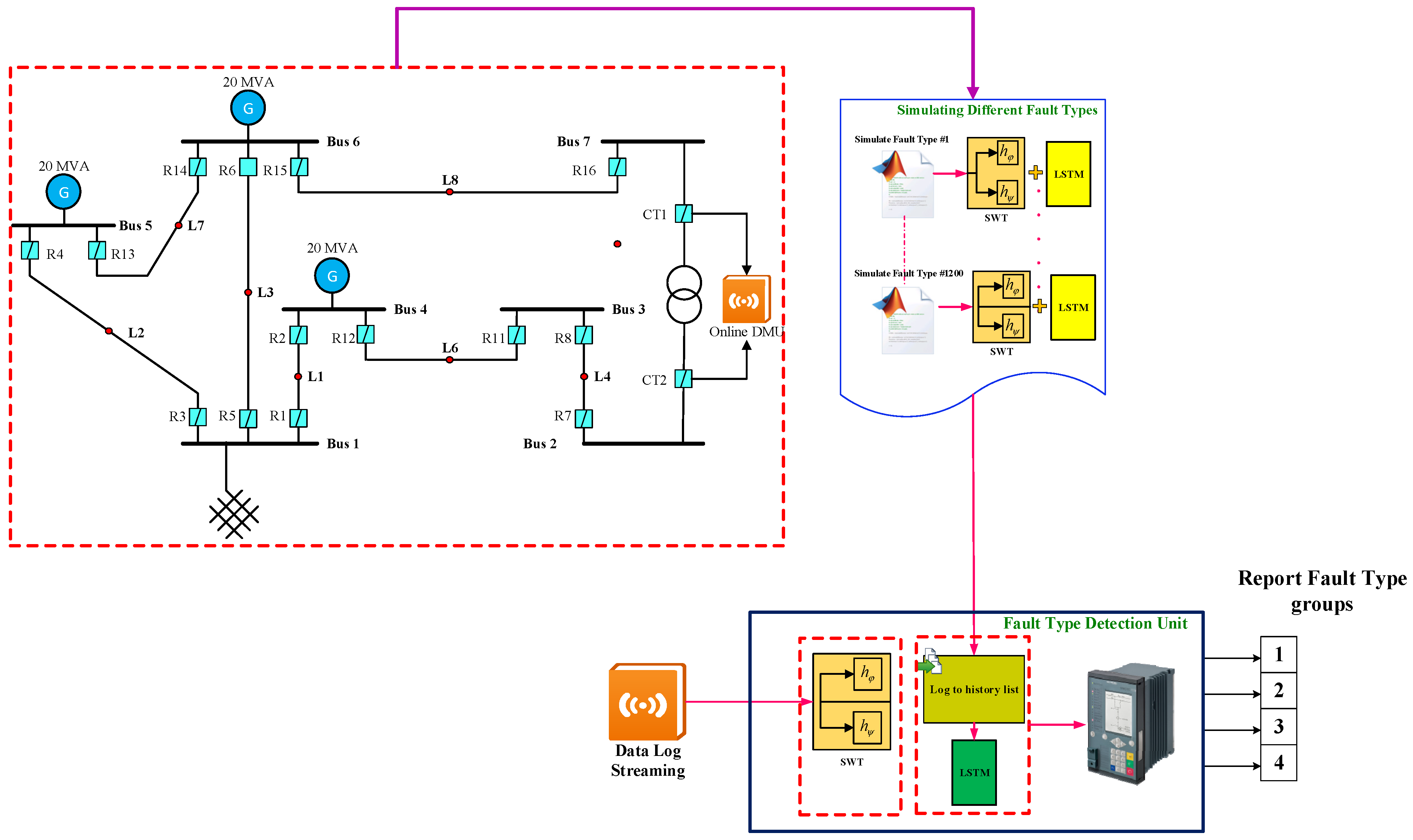
2. Conceptual Model and Problem Procedure

The conceptual design of the proposed intelligent method for identifying and classifying internal electrical faults, external faults during the saturation of CT, and inrush currents in power transformers is shown in Figure 1.
As depicted in this figure, the proposed approach can be implemented on an online platform through the measurement of voltage and current data at the installation site of power transformers within the power grid, even when the measured data are noisy or uncertain. In this design, the internal and external fault currents as well as the inrush currents of power transformers are initially measured by measurement units, which may contain noise or uncertainties. Subsequently, the sampled signals during various events are transferred to MATLAB software for detection and differentiation. At this stage, the features of the sampled signals are determined using advanced wavelet transform. Afterward, the real-time fault detection system, based on the trained advanced long short-term memory (LSTM) neural network, differentiates and identifies the type of fault occurring in the power transformer. The steps for implementing the proposed method are detailed in Algorithm 1 below.
Algorithm 1. Procedure of the Proposed Framework for Internal Fault Detection in Power Transformers
1. Training Stage:
1.1. For k = 1:2000
1.2. If k ≤ 500
1.3. Run the Simulation file for sampling the differential currents of external fault
1.4. SignalVector = Differential currents of external fault
1.5. ElseIf 500 < k ≤ 1000
1.6. Run the Simulation file for sampling the differential currents of inrush current
1.7. SignalVector = Differential currents of inrush current
1.8. ElseIf 1000 < k ≤ 1500
1.9. Run the Simulation file for sampling the differential currents of internal fault without CT saturation
1.10. SignalVector = Differential currents of inrush current internal fault without CT saturation
1.11. ElseIf 1500 < k ≤ 2000
1.12. Run the Simulation file for sampling the differential currents of internal fault with CT saturation
SignalVector = Differential currents of inrush current internal fault with CT saturation
1.13. Call the Improved RTBSWT Function ( x ( t ) )
     S x ( l , k ) = 1 2 l = 0 L 1 h φ ( n ) x ( k L + n + 1 + l ) ,
     w x ( l , k ) = 1 2 l = 0 L 1 h ψ ( n ) x ( k L + n + 1 + l ) ,
1.14. End Call RTBSWT Function
1.15. Call Proposed LSTM Network Function
     i t = σ ( W x i x t + W h i h t 1 + b i )
     f t = σ ( W x f x t + W h f h t 1 + b f )
     c ˜ t = tanh ( W x c x t + W h c h t 1 + b c )
     c t = i t c ˜ t + f t c t 1
     o t = σ ( W x o x t + W h o h t 1 + b o )
     h t = o t tanh ( c t )
1.16. End LSTM Function
1.17. End for (K = 2000)
2. Test and Verification Stage
2.1. Call an unknown differential current ( x ( t ) , y ( t ) )
2.2. Call the Improved RTBSWT Function ( x ( t ) )
2.3. Feature selection of x ( t ) using the 1.13.1 and 1.13.2
2.4. End Call RTBSWT Function
2.5. Call Proposed LSTM Network Function
2.6. y ( t ) = predict the signal type using the trained LSTM Network
2.7. End LSTM Function
2.8. Calculate the RSME ( y ( t ) , y ( t ) )
2.9. End Stage 2

3. Problem Statement and Mathematical Formulation

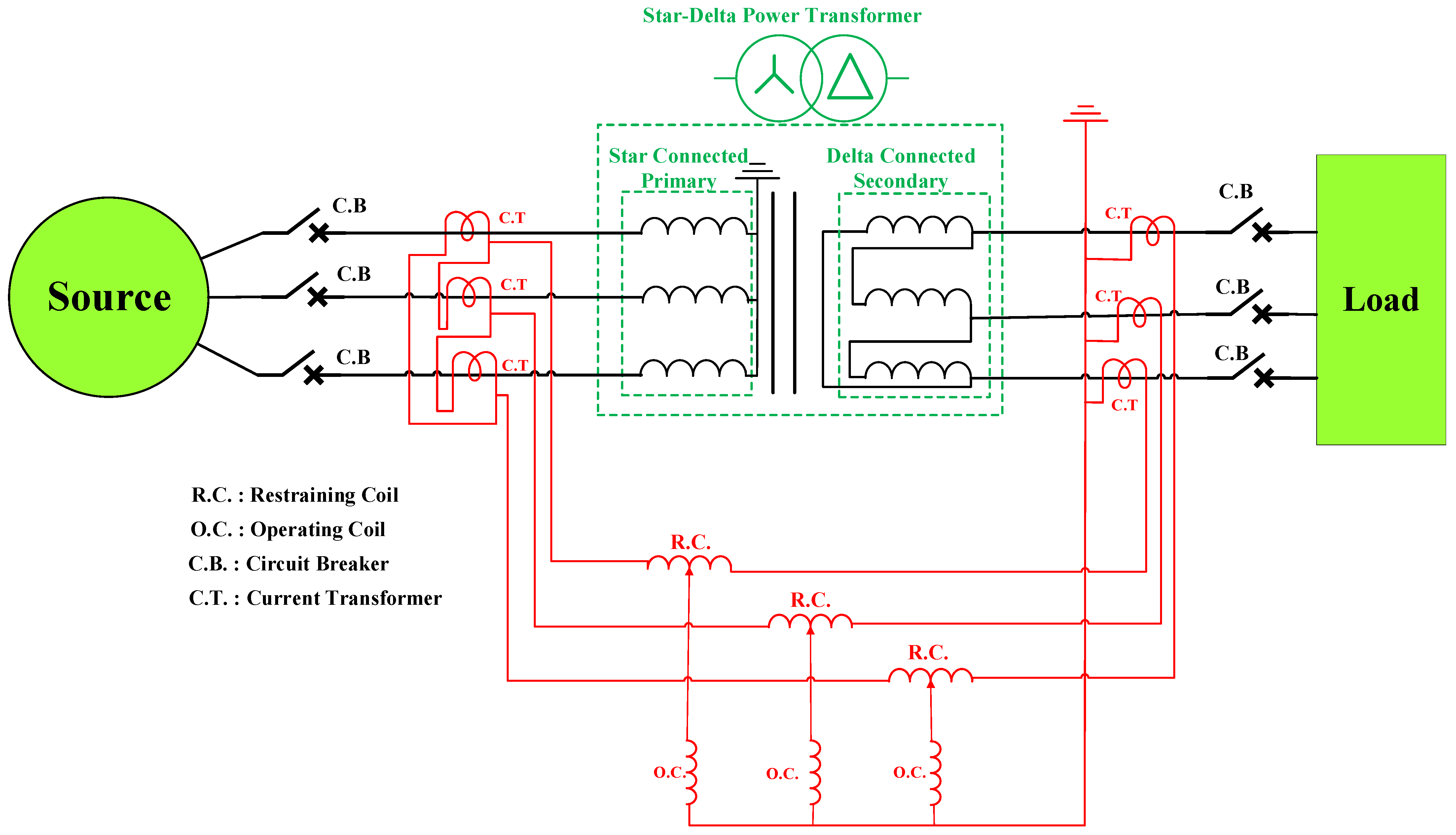
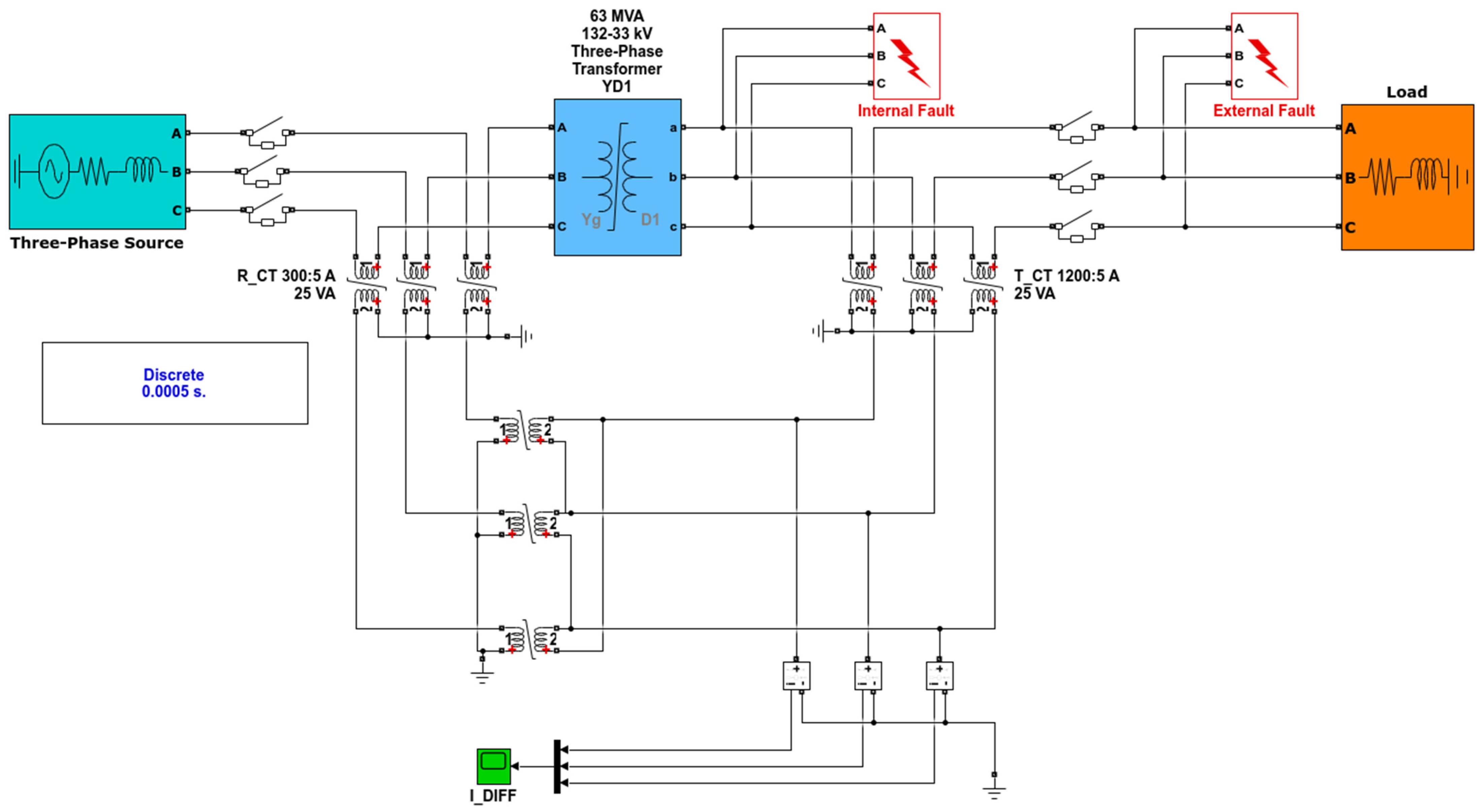
3.1. Structure of Differential Current Measuring

In this part, differential current is generated by employing CTs on both the primary and secondary sides of the power transformer. The correct CT ratio is essential for this setup, and the star-delta connection of the CTs must be precisely configured according to the power transformer’s connection type. Figure 2 shows the structure of the differential current measurement system, including the CT connections and the differential current calculation. This differential current flows through the operating winding of the differential protection relay. During fault conditions, the current passing through the CT can greatly exceed its rated capacity, leading to the saturation of the CT core. Moreover, when a fault occurs, particularly during asymmetrical faults, a DC component can be superimposed on the AC waveform. This DC offset can drive the CT core to saturation. Additionally, the presence of harmonics in the current, caused by nonlinear loads or power electronics, can also contribute to the saturation of the CT core.

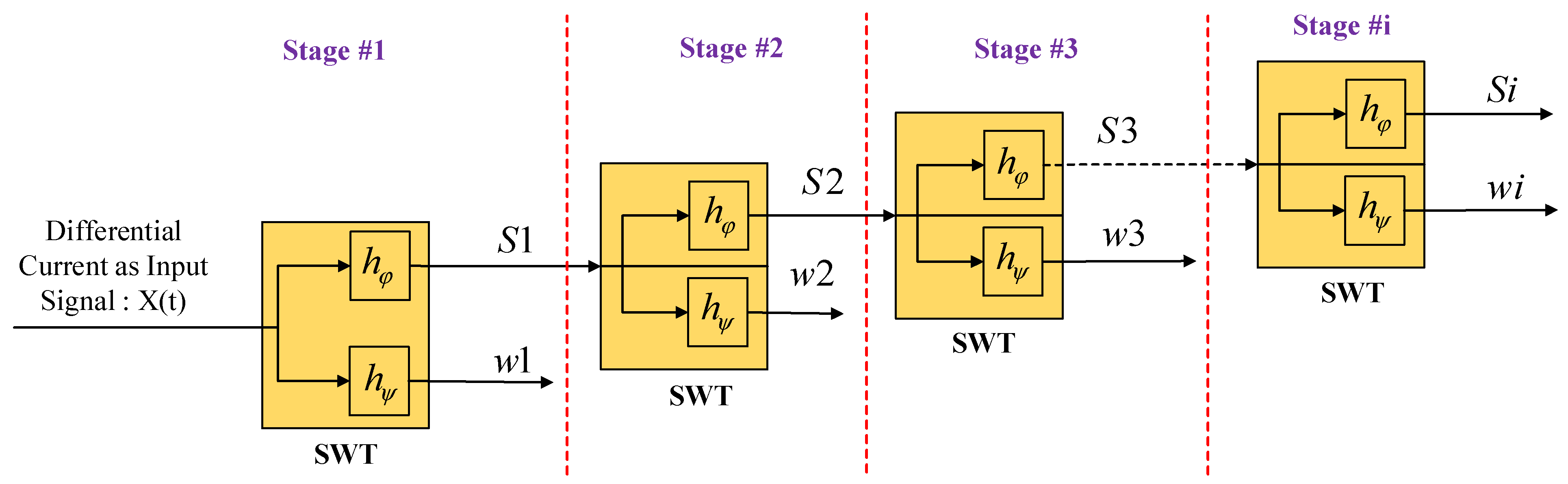
3.2. Wavelet Transform (Stationary State)—SWT

Derived from the DWT, the SWT is a time–frequency decomposition method where the input signal becomes invariant in time without being downsampled by the filters. As a result, the SWT method is better suited for real-time applications because it offers a faster transient detection than the DWT [34]. Figure 3 illustrates the filtering process without the two-fold downsampling.
The SWT’s scaling and wavelet coefficients are defined similarly to the DWT’s:
S j ( k ) = 1 2 n = h φ ( n k ) x j 1 ( n ) ,
w j ( k ) = 1 2 n = h ψ ( n k ) x j 1 ( n ) ,
where j > 1 . The wavelet and scaling coefficients can also be computed at the first decomposition level for a sequence of k f samples using a matrix generated by the SWT’s pyramidal algorithm as follows:
S 1 = 1 2 H φ x
w 1 = 1 2 H ψ x
where the square matrices H φ and H ψ have orders equal to k f . The filter coefficients H φ and H ψ are circularly displaced to form the matrices H φ and H ψ , respectively.
H φ = h φ ( 3 ) 0 0 0 0 h φ ( 0 ) h φ ( 1 ) h φ ( 2 ) h φ ( 2 ) h φ ( 3 ) 0 0 0 0 h φ ( 0 ) h φ ( 1 ) h φ ( 1 ) h φ ( 2 ) h φ ( 3 ) 0 0 0 0 h φ ( 0 ) h φ ( 0 ) h φ ( 1 ) h φ ( 2 ) h φ ( 3 ) 0 0 0 0 0 0 0 0 h φ ( 0 ) h φ ( 1 ) h φ ( 2 ) h φ ( 3 )
H ψ = h ψ ( 3 ) 0 0 0 0 h ψ ( 0 ) h ψ ( 1 ) h ψ ( 2 ) h ψ ( 2 ) h ψ ( 3 ) 0 0 0 0 h ψ ( 0 ) h ψ ( 1 ) h ψ ( 1 ) h ψ ( 2 ) h ψ ( 3 ) 0 0 0 0 h ψ ( 0 ) h φ ( 0 ) h φ ( 1 ) h φ ( 2 ) h φ ( 3 ) 0 0 0 0 0 0 0 0 h ψ ( 0 ) h ψ ( 1 ) h ψ ( 2 ) h ψ ( 3 )
Equations (3) and (4) can therefore be rewritten as follows:
S 1 ( 0 ) S 1 ( 1 ) S 1 ( 2 ) S 1 ( 3 ) S 1 ( k t ) = 1 2 H φ x 1 ( 0 ) x 1 ( 1 ) x 1 ( 2 ) x 1 ( 3 ) x 1 ( k t )
w 1 ( 0 ) w 1 ( 1 ) w 1 ( 2 ) w 1 ( 3 ) w 1 ( k t ) = 1 2 H ψ x 1 ( 0 ) x 1 ( 1 ) x 1 ( 2 ) x 1 ( 3 ) x 1 ( k t )
Equations (7) and (8) state that the first three scaling and wavelet coefficients are calculated from the initial and final signal samples, using the db4 wavelet filter at the first decomposition level. As a result, it is probable that some coefficients exhibit amplitude values that differ from those of the others, indicating a phenomenon called the border effect.

3.2.1. Real-Time Stationary Wavelet Transform (RT-SWT)

In order to compute the scaling and wavelet coefficients, the traditional SWT pyramid algorithm, according to [35], requires all samples of the analyzed signal, which is impractical for real-time applications. In addition, if the signal is circular and periodic, border distortions might happen. Consequently, in the first decomposition level, the RT-SWT computes the scaling S x and wavelet w x coefficients in the manner described below [35]:
S x ( k ) = 1 2 l = 0 L 1 h φ ( l ) x ( k + l L + 1 ) ,
w x ( k ) = 1 2 l = 0 L 1 h ψ ( l ) x ( k + l L + 1 ) ,
where S x and w x can be obtained with just L samples. As a result, in order to produce results comparable to those of SWT, RT-SWT does not require all of the signal samples. The window shifts because a new sample is added to the window and an older sample is removed at each sampling step ( 1 / f s seconds). With the exception of the first L 1 coefficients, which cannot be computed in real time and may present coefficients with border distortions of the signal sliding window, the wavelet coefficients of the main window computed in real time with the RT-SWT algorithm are the same wavelet coefficients calculated by the SWT pyramid algorithm [35].

3.2.2. Improved Wavelet Transform (Real-Time Boundary Stationary)

As previously mentioned, border distortions may result from the RT-SWT’s computation of scaling and wavelet coefficients for periodic and circular signals. In this work, border effects will be implemented to give more information in order to achieve fast fault detection [36].
In the following manner, the first level of the real-time boundary stationary wavelet transform (RTBSWT) scaling and wavelet coefficients related to the current sampling k are calculated by inner products between L samples of the time-domain signal x inside a circular sliding window x with δ k samples and L coefficients of the scaling H φ and wavelet H ψ filters [36]:
S x ( l , k ) = 1 2 l = 0 L 1 h φ ( n ) x ( k L + n + 1 + l ) ,
w x ( l , k ) = 1 2 l = 0 L 1 h ψ ( n ) x ( k L + n + 1 + l ) ,
where the current sampling time, k / f s , is associated with k > Δ k 1 ; the sliding window length is Δ k > L ; the border distortion index is 0 < 1 < L ; and the periodized signal in Δ k samples is x ( k + m ) = x ( k Δ k + m ) with m N .
x is broken down into L scaling and wavelet coefficients, as shown by Equations (11) and (12). These are composed of s ( 0 , k ) = s ( k ) and w ( 0 , k ) = w ( k ) , which correspond to the RT-SWT scaling and wavelet coefficients, and s ( l , k ) and w ( l , k ) with l = 0 , which are L 1 coefficients known as boundary coefficients (coefficients with border distortions).
The boundary coefficients in the RTBSWT algorithm are ascertained using a few last and first samples of the signal sliding window. Since the first transient-affected sample is grouped with samples from steady-state operations, there are notable variations in the magnitudes of SWT coefficients and those computed with border effects. Then, when transients affect a sample, using boundary coefficients rather than the traditional ones may present a highest magnitude, which facilitates the detection of disturbances.

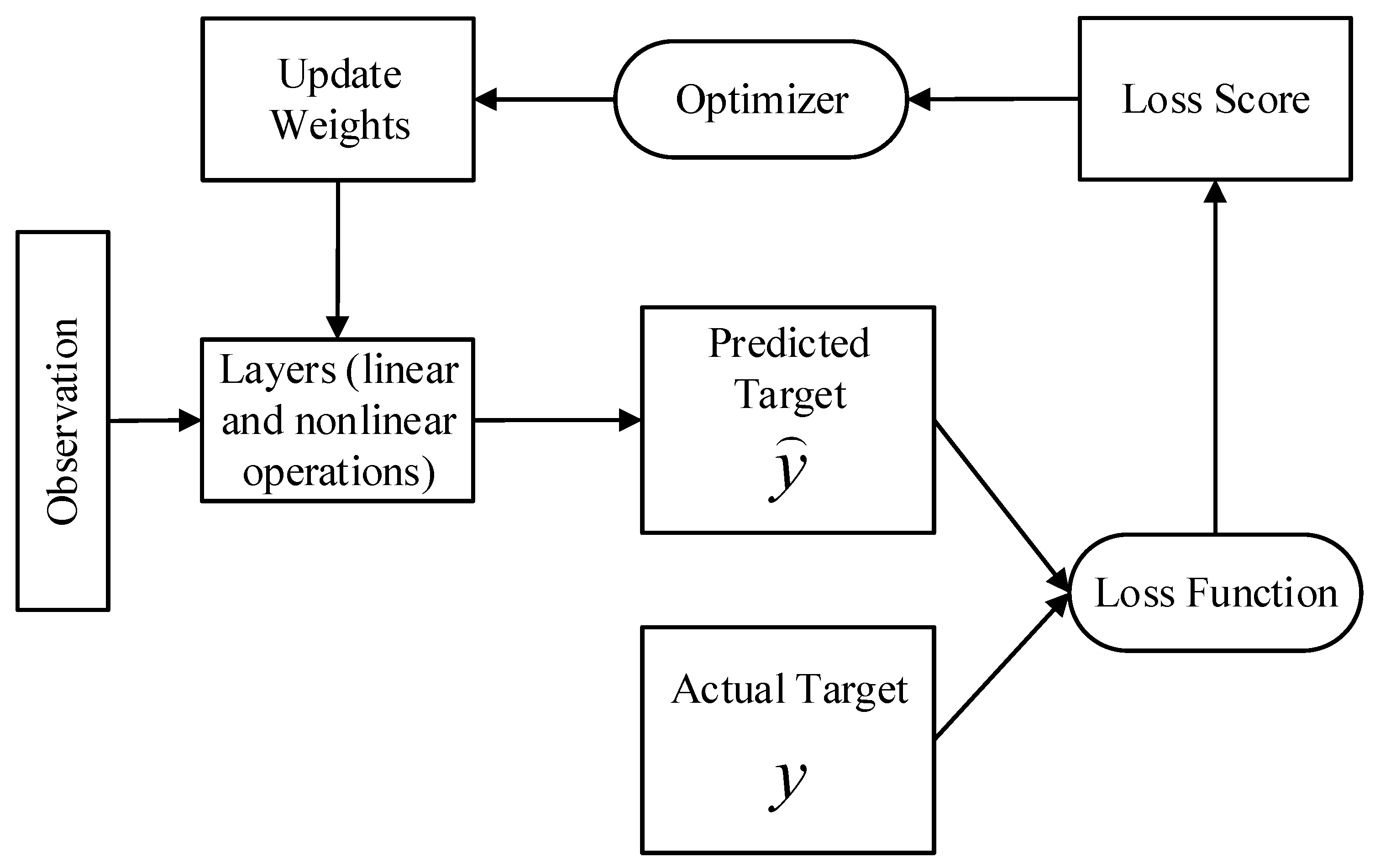
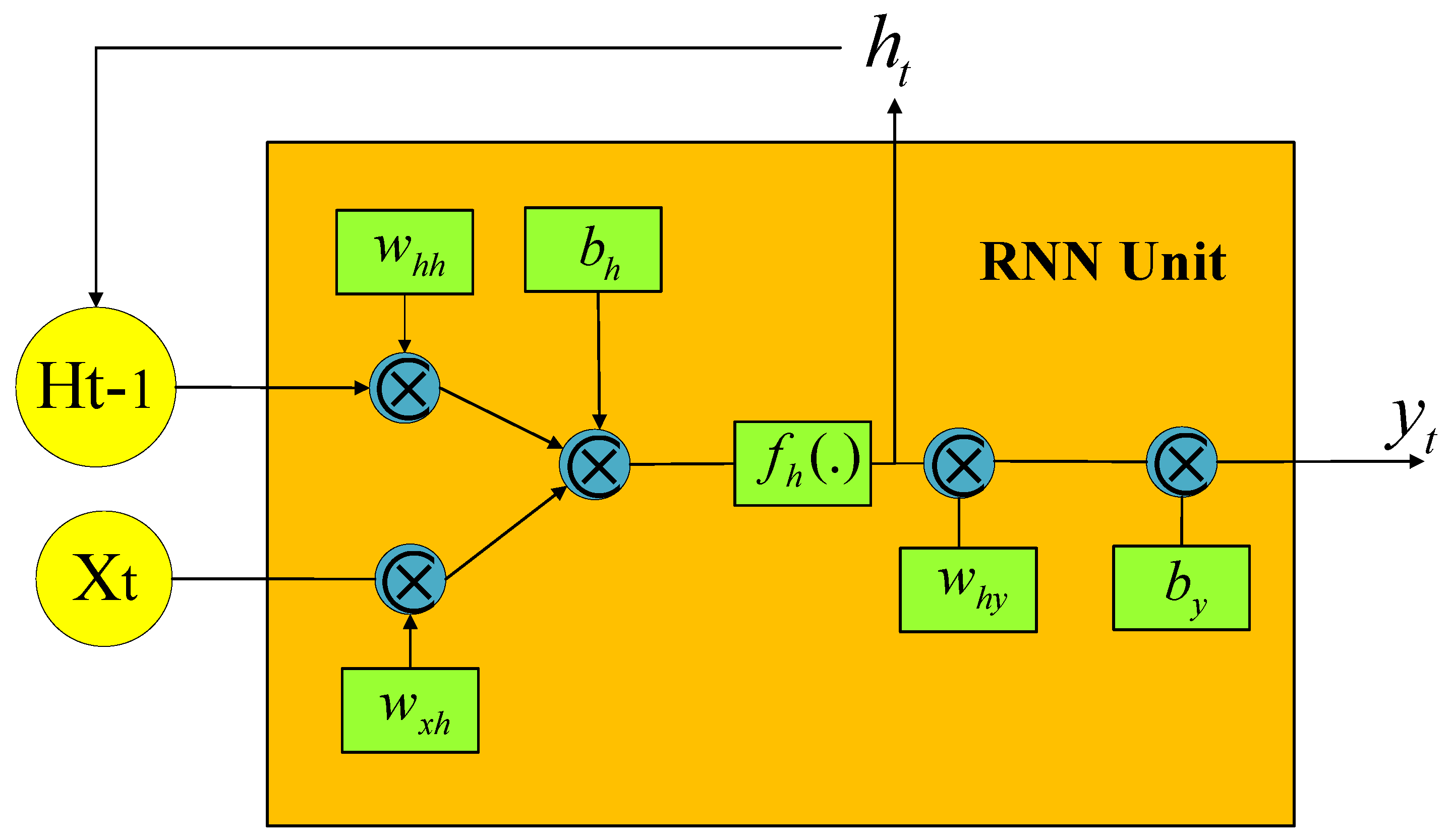
3.3. Enhanced LSTM Neural Network

To implement a meaningful mapping between a set of observations and a response variable, artificial neural networks (ANNs) employ a combination of linear and nonlinear operations. A network’s depth is the number of successive transformation layers that it uses. Using ANNs with multiple layers to implicitly extract underlying patterns from data at progressively higher abstraction levels is the aim of deep learning [37]. Because of this, deep neural networks (DNNs) typically do not need an additional feature extraction step, such as the one used in [38], to estimate the parameters of the sinusoidal model. It is necessary to estimate the weights of the linear operations used in DNN layers during the training phase based on observations, as they are currently unknown. A detailed discussion of the algorithms used to train DNNs can be found elsewhere [39,40]. A schematic representation of this training procedure is shown in Figure 4.
Recurrent neural networks (RNNs) function based on a set of internal states in addition to input observations, which sets them apart from feed-forward networks in a fundamental way [41,42]. The internal states record historical data in sequences that the network has already processed. In other words, the network has a cycle that enables the retention of historical data for a period of time that is dependent on the observations and weights it receives as input rather than being fixed a priori. Therefore, an RNN is a dynamic system capable of learning sequential dependencies extended over time, unlike other common DNN architectures that implement a static input–output mapping. It has therefore been widely utilized for time-series analysis [43].
In this instance, we codify the RNN dynamics. The k × 1 , m × 1 , and L × 1 vectors of input observations, hidden states, and output vectors, respectively, can be represented by the symbols x t , h t , and y t and ( h 1 , h 2 , , h T ) and ( y 1 , y 2 , , y T ) are computed given an input sequence ( x 1 , x 2 , , x T ) by iterating through the following recursive equations for t = 1 , , T [44]:
h t = f h ( W x h x t + W h h h t 1 + b h )
y t = W h y h t + b y
where M × K , M × M , and L × M weight matrices are represented by W x h , W h h , and W h y ; M × 1 and L × 1 bias terms are represented by b h and b y ; and an element-wise nonlinear hidden layer function (such as the logistic sigmoid function) is represented by f h . An illustration of a fundamental RNN unit described by Equations (13) and (14) is shown in Figure 5.
Since a basic RNN unit unfolds over time to become a composite of several nonlinear computational layers, it is already temporally deep [39]. In addition to the temporal depth of an RNN, Pascanu et al. investigated several alternative definitions of depth in RNNs, which allowed for the construction of deep RNNs [40]. Nonetheless, piling several recurrent hidden layers on top of one another is a standard method of defining deep RNNs [40]. In this instance, the output of the layer before it forms the input of that layer. With N hidden layers assumed, the hidden states for layer j are iteratively calculated for j = 1 , , N and t = 1 , , T using the following formula:
h t j = f h ( W h j 1 h j h t j 1 + W h j h j h t 1 j + b h j )
y t = W h N y h t N + b y
where the same hidden layer operates. It is assumed that f h for every layer exists, where h t 0 = x t and h t j represents the state vector of the j t h hidden layer. RNNs have a strong and intuitive structure, but when trained in real-world scenarios, they are unable to capture long-term dependencies. Generally speaking, this situation is related to the vanishing gradient and exploding gradient issues mentioned in [37,43]. More advanced recurrent units, such as enhanced long short-term memory (ELSTM) units and, more recently, gated recurrent units (GRUs), have been proposed to address issues with basic RNNs. In addition to being easier and more effective to train than LSTMs, GRUs have demonstrated performance levels that are comparable to those of LSTM architectures [44]. Formally, a GRU [44] uses the following approximate function to try and implement the hidden layer function f h in Equation (13):
z t = σ ( W x z x t + W h z h t 1 + b z )
r t = σ ( W x r x t + W h r h t 1 + b r )
h ˜ t = tanh ( W x h x t + W h ( h t 1 r t ) + b h )
h t = z t h t 1 + 1 z t h ˜ t
where ⨀ stands for multiplication of elements, The weight matrices M × K , M × K , M × K , and M × M are represented by W x z , W x r , W x h , and W h ; the m × 1 bias terms are represented by b z , b r , and b h ; the M × 1 (update gate) vector and M × 1 (rest gate) vector are represented by Z t and r t , respectively. GRUs can be stacked on top of one another to create a deeper network, much like simple RNN units. Under such circumstances, Equations (17)–(20) are extended to all layers, much like Equation (15). However, the hidden layer function f h in Equation (13) is implemented by the following composite function in the proposed LSTM:
i t = σ ( W x i x t + W h i h t 1 + b i )
f t = σ ( W x f x t + W h f h t 1 + b f )
c ˜ t = tanh ( W x c x t + W h c h t 1 + b c )
c t = i t c ˜ t + f t c t 1
o t = σ ( W x o x t + W h o h t 1 + b o )
h t = o t tanh ( c t )
where b i , b f , b c , and b 0 denote M × 1 bias terms; i t , f t , c t , and o t denote M × 1 (input gate) vector, M × 1 (forget gate) vector, M × 1 (cell state) vector, and M × 1 (output gate) vector, respectively; W x i , W x f , W x c , and W x o denote M × K ; W h i , W h f , W h c , and W h o denote M × M weight matrices. The reason the models up to this point have been referred to as unidirectional RNNs is that only observations x 1 , x 2 , , x t are utilized in order to predict y t ; in other words, information flows from the past to the present and future observations are not utilized in order to predict y t . The bidirectional LSTM neural network that can use data from the “future” to predict y t is proposed in this paper. In this sense, a different set of hidden layers is identified and linked in a different temporal sequence. Formally, the following modification to Equation (13) yields this:
h t f = f h ( W x h f x t + W h h f h t 1 f + b h f )
h t b = f h ( W x h b x t + W h h b h t + 1 b + b h b )
y t = W h y f h t f + W h y b h t b + b y
where W x h f , W h h f , W x h b , W h y b , b h f , b h b , and b y are weight matrices and bias terms that need to be calculated in the right size.
In the current study, the model is trained to minimize the error between the predicted output and the actual labels using a suitable loss function, such as binary cross-entropy loss. Backpropagation through time (BPTT) or alternative optimization algorithms like Adam or RMSprop are used to update the network parameters. Where:
  • y t : Binary coding vector using (0,1) for various types of faults in power transformers.
In this study, different types of faults have been encoded as the output of the proposed LSTM, as shown in Table 1.

4. Result Analysis and Discussion

In the study presented, the proposed framework was tested and validated through a simulation case, illustrated in Figure 6. A comprehensive approach was adopted, incorporating numerous case studies using a blend of simulation techniques, real-world data, and data augmentation methods. This multifaceted strategy allowed the methodology to be validated across various experimental scenarios. Specifically, a simulation model of a 132/33 kV power transformer with a 63 MVA capacity was created, meticulously calibrated to match a real-world counterpart under different fault conditions. Detailed specifications of the transformer under study are provided in Table 2. This calibration enabled the accurate replication of the real transformer’s behavior under diverse operating conditions and fault scenarios. Throughout the process, the measured signals at each simulation step were rigorously compared to ensure consistency with those observed in the real transformer under identical conditions. Additionally, data from multiple sources—including simulated, real-world, and augmented datasets—were integrated to construct a comprehensive training dataset. This approach ensured that the synthesized data authentically reflected real-world transformer operations and fault conditions. The robustness and capability of the model to handle a wide range of experimental data in real-world scenarios were ensured through this thorough and integrative approach, providing a strong foundation for validating and ensuring the reliability of the methodology.
The simulation was designed to emulate a real-world power transformer, considering source phase angles ranging from 0 to 360 degrees to cover all possible transformer switching conditions. Additionally, various load scenarios and multiple cases of internal faults with varying ground resistance were simulated. A total of 2000 cases were gathered through a comprehensive approach that combined simulations with real-world data and data augmentation techniques. These cases were used for training and validating the LSTM network. Data augmentation methods included introducing noise, applying transformations such as scaling and rotation, and generating synthetic samples using techniques like the synthetic minority over-sampling technique (SMOTE). Diverse data sources—simulated, real-world, and augmented data—were integrated to create an extensive training dataset. Throughout this process, it was ensured that the synthesized data accurately represented the underlying distribution of transformer operations and fault conditions. According to the Table 3, the data collection approach systematically explored different scenarios, as detailed in the following points:
  • Running the power system with varying power supply phase angles (0–360°).
  • Modifying fault ground resistance within a range (0.001, 0.01, 0.1, 1, 2, 10, …, 75, 125, 150).
  • Adjusting transformer load from 5 MVA to 33 MVA.
  • Manipulating fault location timing on both the LV side (33 kV) and HV side (132 kV) as per the provided table.
Table 3. Various fault scenarios in the power transformer for training and testing the proposed framework.
CasesPower Source Phase AngleNumber of CasesFault LocationFault Ground ResistanceTransformer Load
Inrush current(0–360°)500---
Internal faults with and without CT saturation(0–360°)500HV and LV(0.001, 0.01, 0.1, …, 75),(5 MVA to 33 MVA)
500HV and LV
External faults under CT saturation(0–360°)250HV(0.001, 0.01, 0.1, …, 75, 125, 150),(5 MVA to 33 MVA)
250LV
Overall, the data collection efforts, with a strong emphasis on simulation, were meticulously conducted to encompass a wide array of scenarios and conditions. This comprehensive approach ensured the robustness and reliability of the study, providing valuable insights into transformer behavior under various operational and fault conditions.

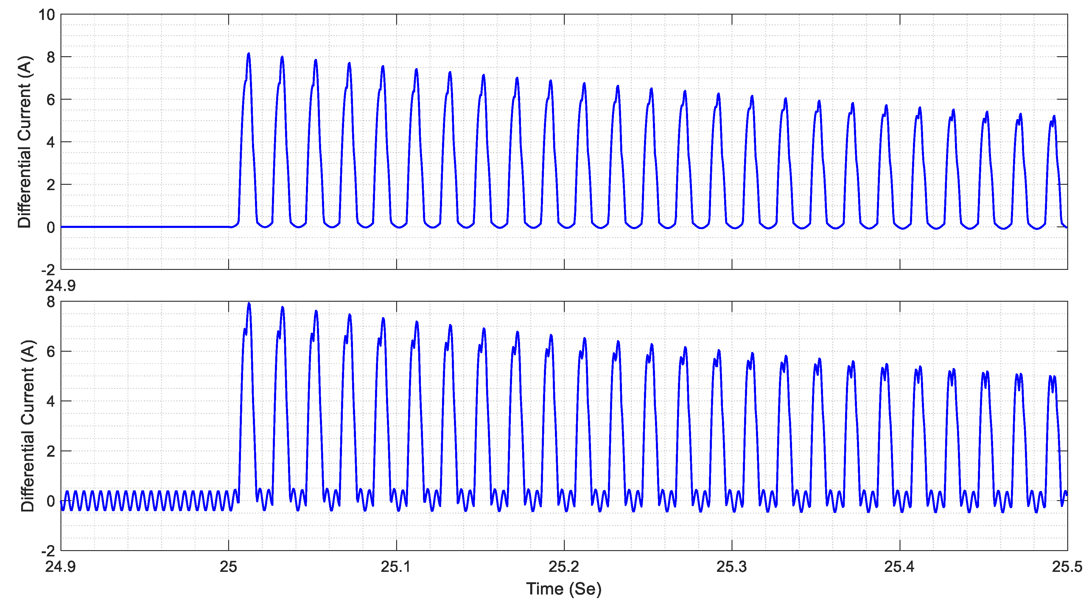
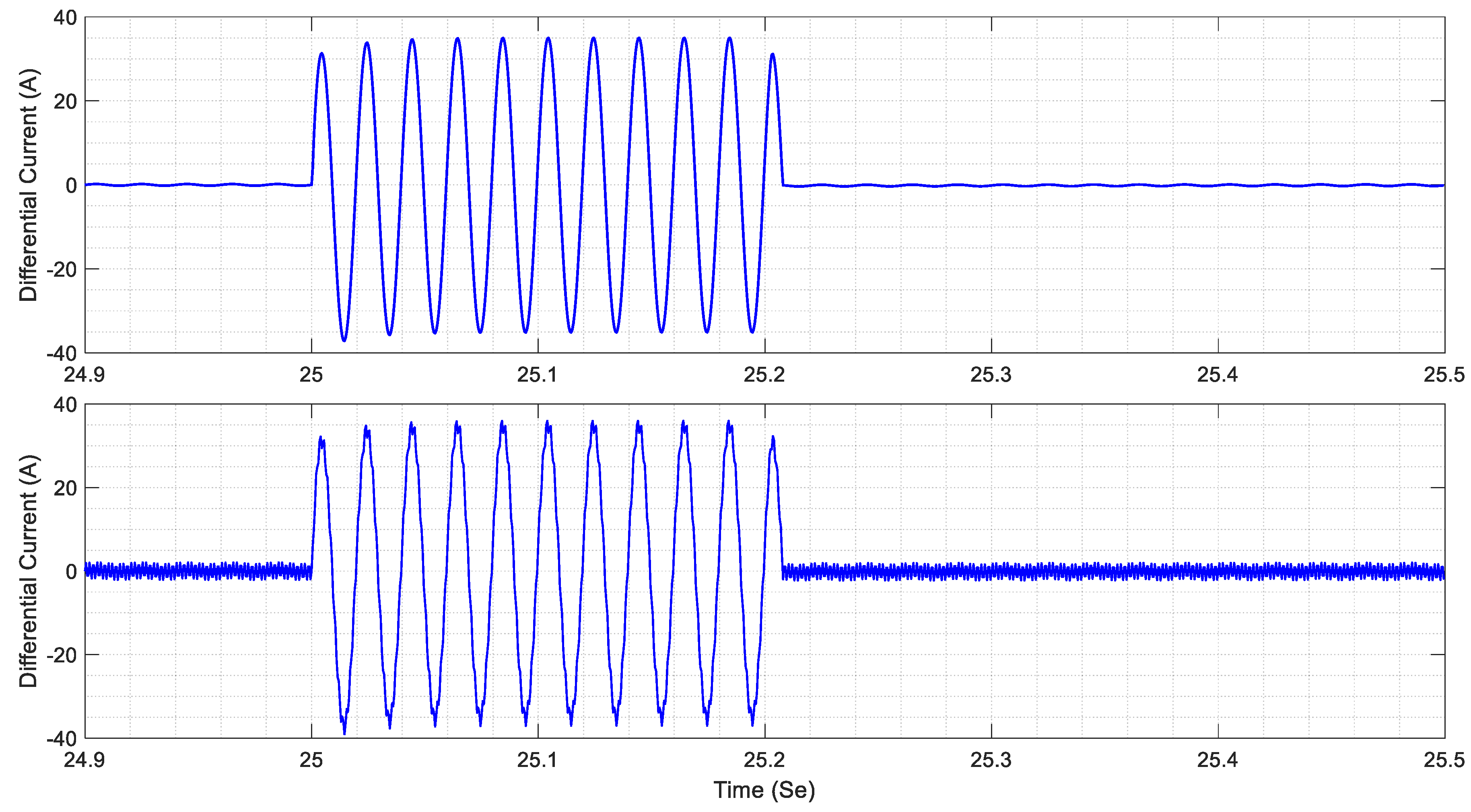
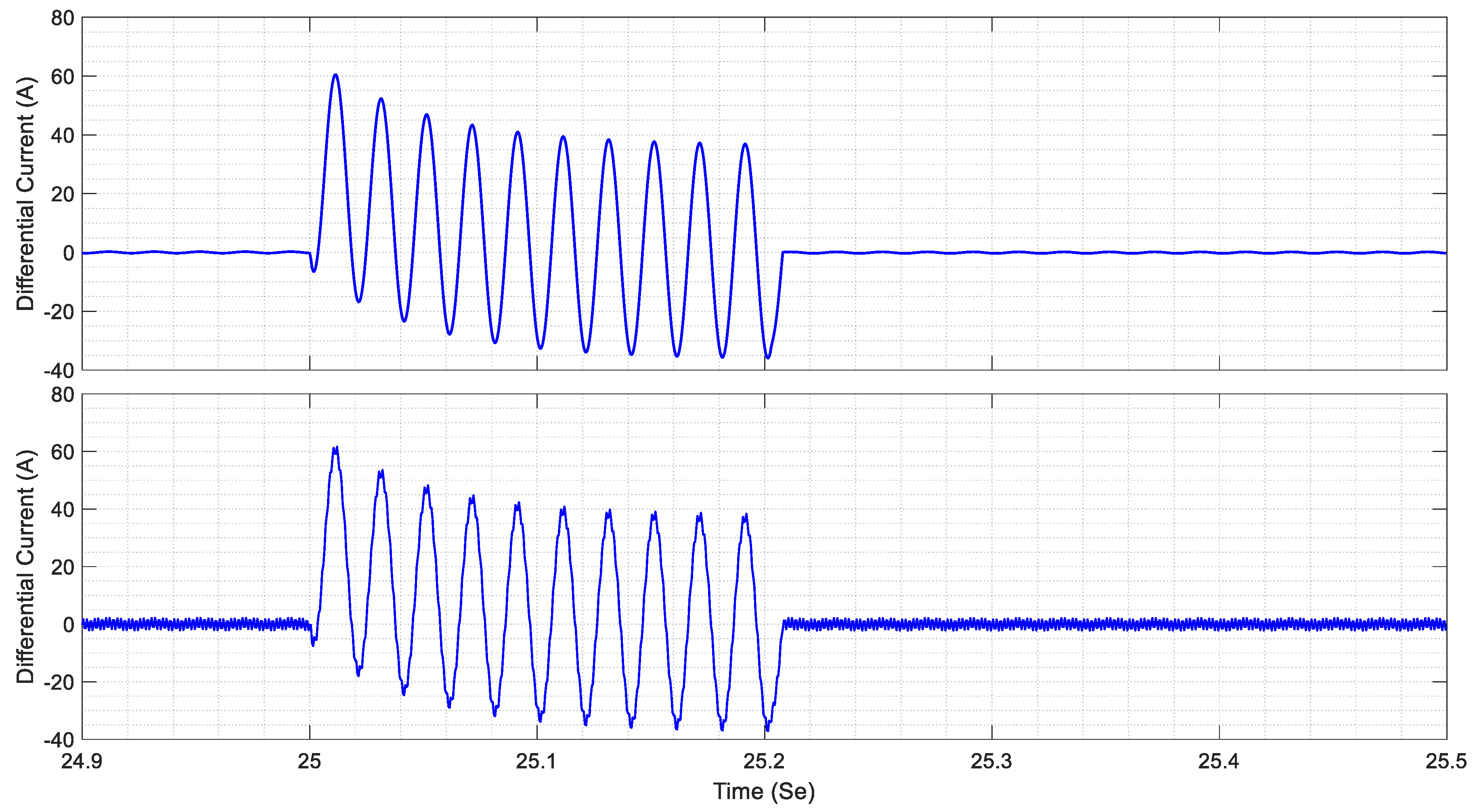
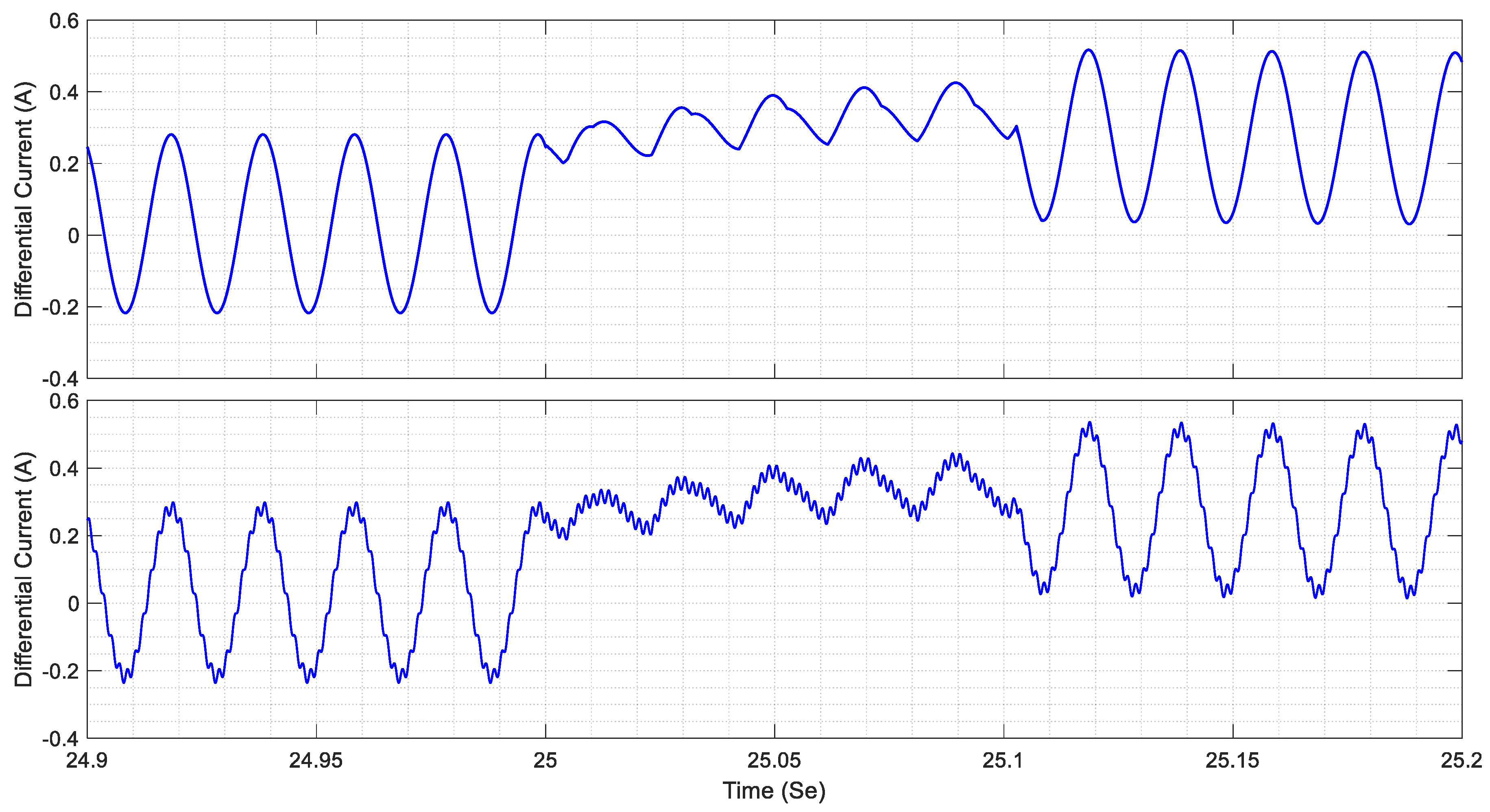
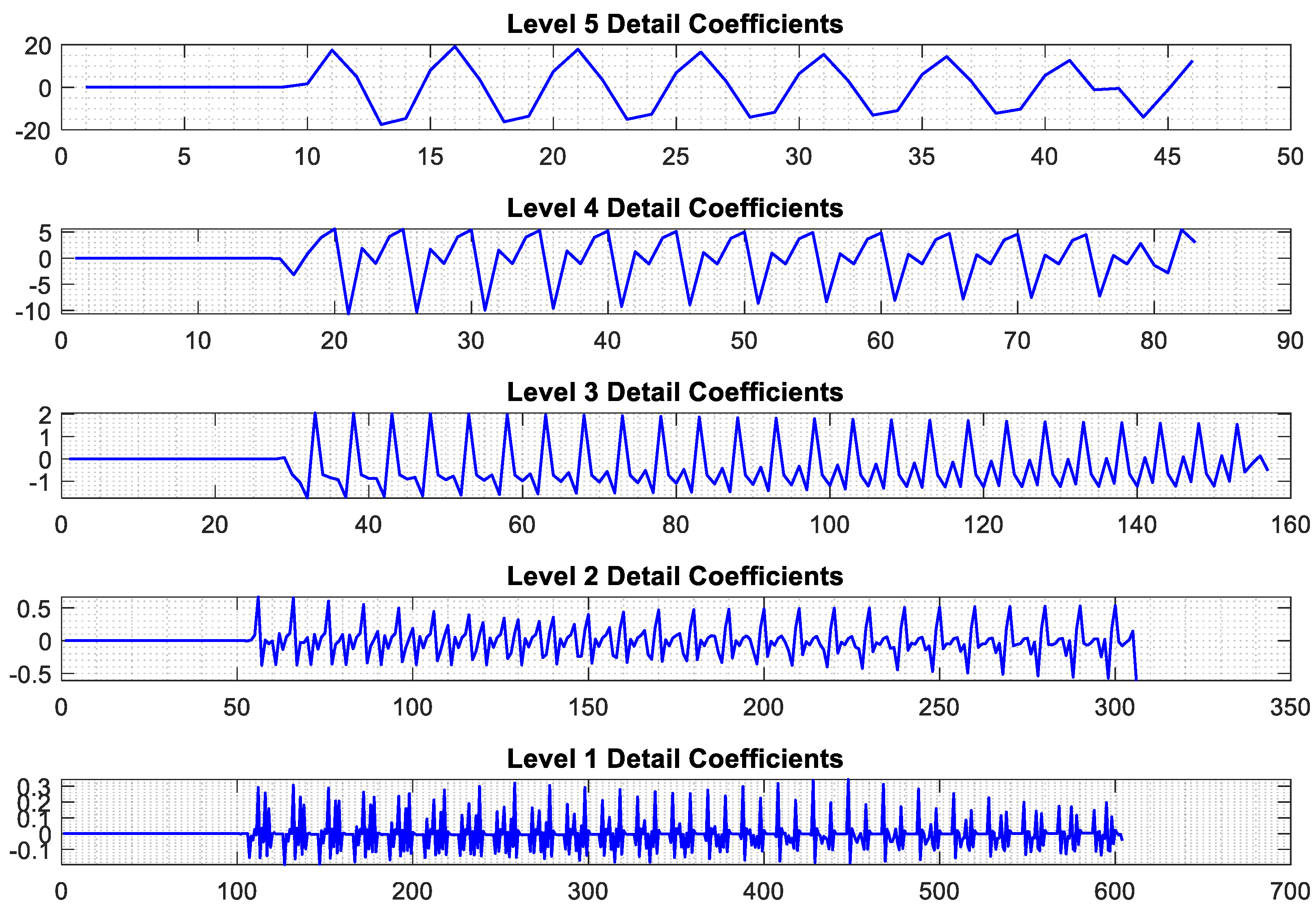
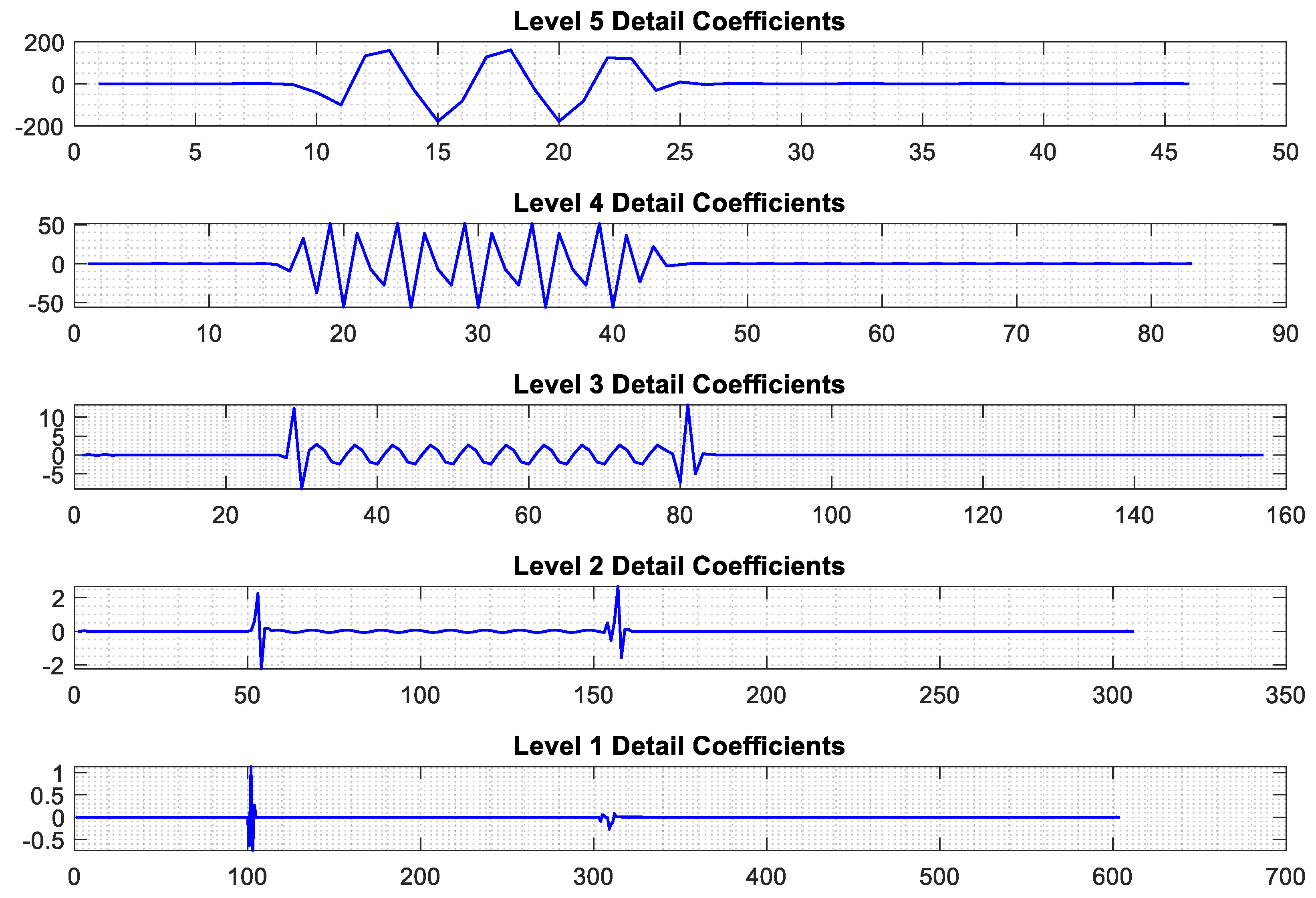
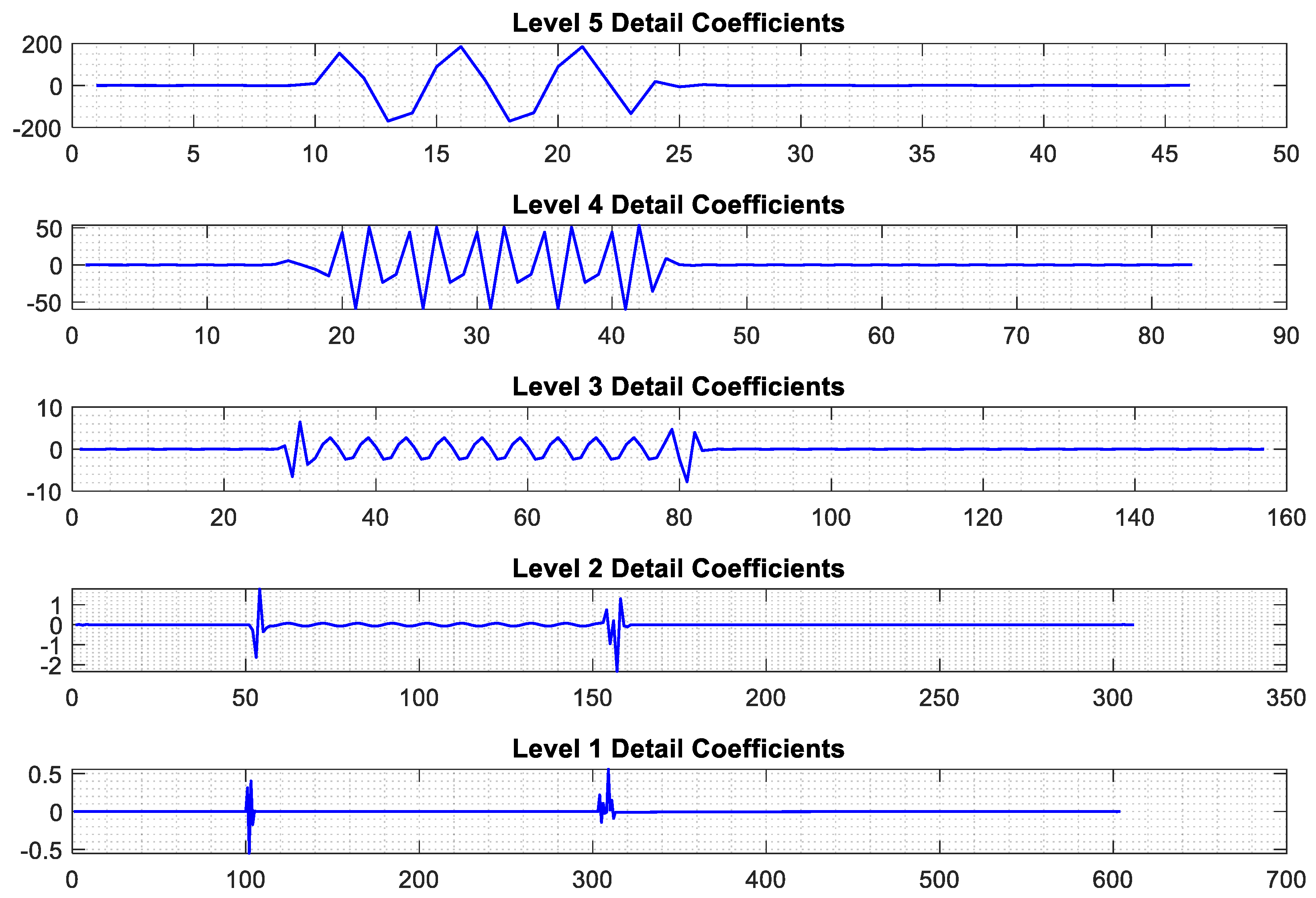
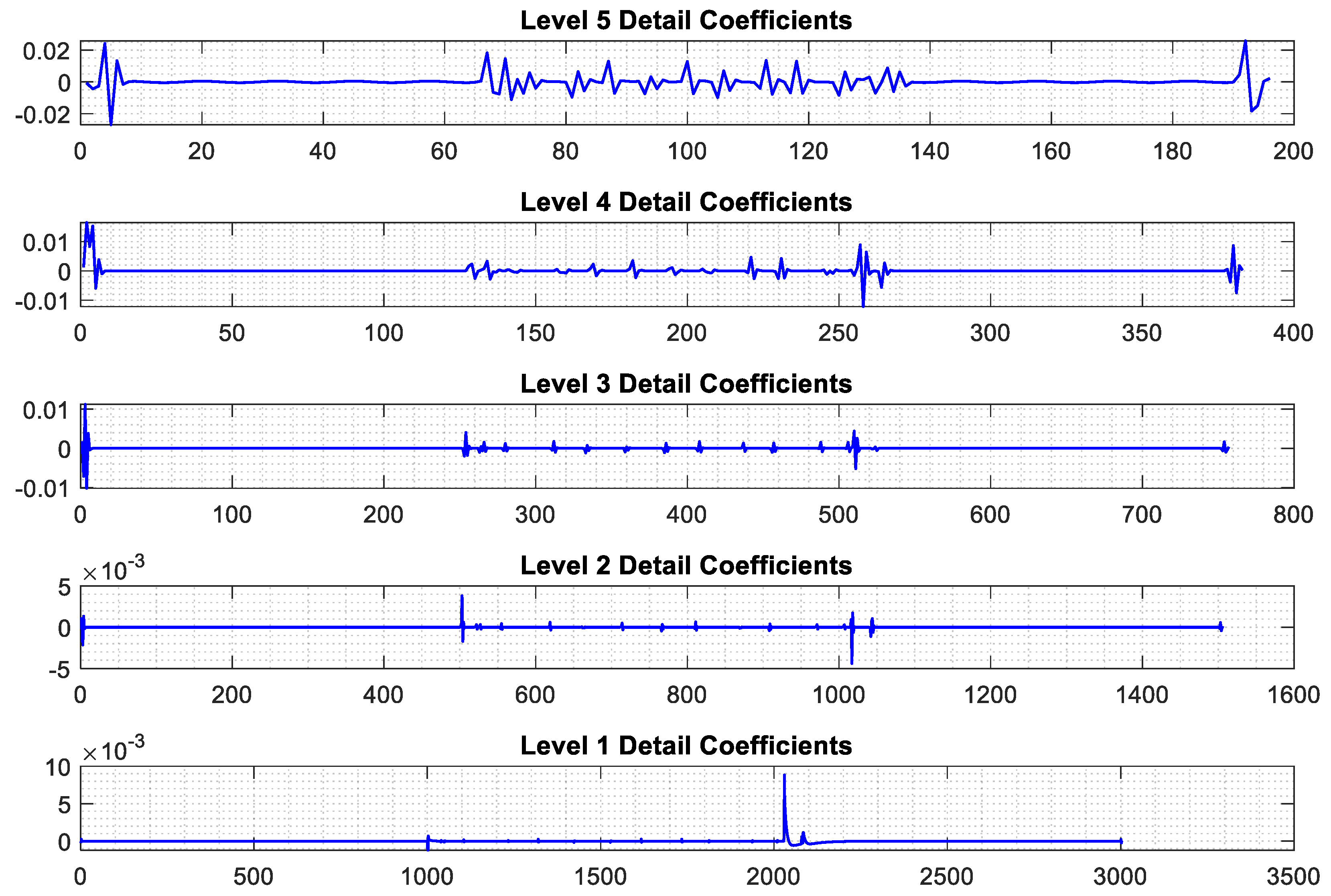
4.1. Feature Extraction Using Improved RBSWT

In this subsection, the feature extraction process for various signal tests of a faulted power transformer is addressed, focusing on external fault with saturation, internal faults, inrush currents, and internal faults occurring simultaneously with CT saturation, as discussed in the previous subsection. Figure 7, Figure 8, Figure 9 and Figure 10 depict these signals both with and without the inclusion of white noise. It should be noted that in the external fault scenario depicted in Figure 10, a three-phase short circuit to ground fault is used to ensure the absolute condition of saturation.
As shown in Figure 7, inrush currents exhibit a rapid increase in magnitude at the onset of space gaps, transitioning either from zero to a significant value or from a specific value back to zero. This abrupt change in current results in smooth ripples along the signal’s length as it swiftly shifts between different states. Upon inspecting the shape of the decomposition details depicted in Figure 11, Figure 12, Figure 13 and Figure 14 both the origin and detail coefficients of each faulted signal reveal discernible features. These features are indicative of distinct characteristics within the signal, which can be effectively captured and utilized for further analysis and diagnosis. On the other hand, the wavelet decomposition of each faulted signal is shown in Figure 11, Figure 12, Figure 13 and Figure 14. These wavelet decompositions can be used for extracting the component levels of the faulted signals. This process allows for a detailed analysis of the signal components, providing valuable insights into the nature and characteristics of each fault.
Additionally, the analysis of these features provides valuable insights into the behavior of the power transformer under various fault conditions. By examining the detail coefficients, one can identify specific patterns and anomalies associated with each type of fault. This information is crucial for developing robust diagnostic tools and improving the reliability of fault detection methods. The detailed examination of inrush currents, external and internal faults, and CT saturation effects allows for a comprehensive understanding of transformer performance and enhances the accuracy of the proposed framework.
It is noteworthy that the settings for differential protection were set up to handle all kinds of external faults, particularly those that arise when CT saturation is present. A wavelet analysis of the current signal was carried out with a ground fault resistance of 0.1 Ω in the event of an external fault involving three-phase and ground faults (ABC-G) outside the protected zone of the power transformer (such as three-phase faults occurring on the load side). In order for the protection mechanisms to be able to respond to and lessen the effects of such faults, it was necessary to precisely identify and characterize the fault conditions.

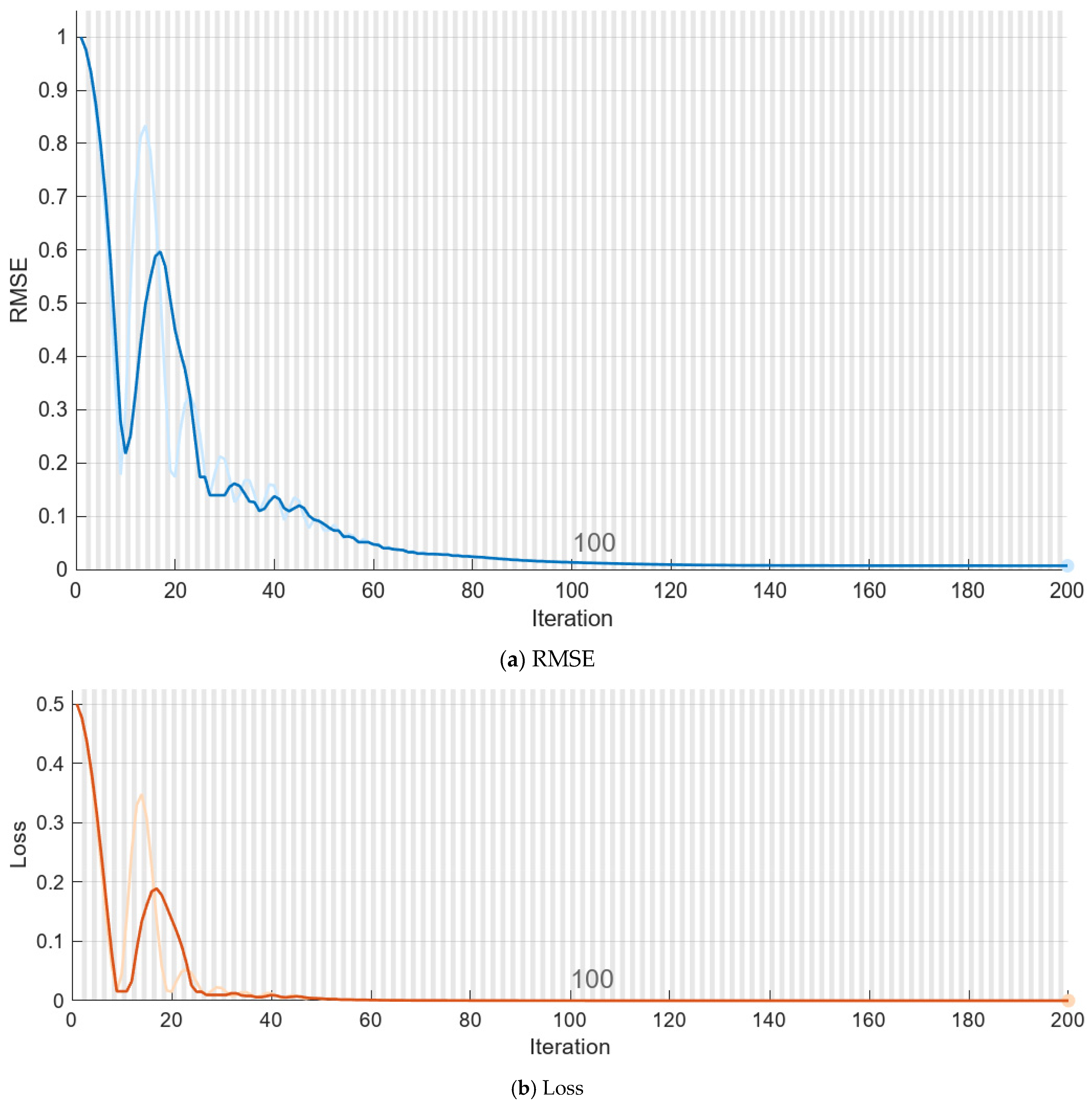
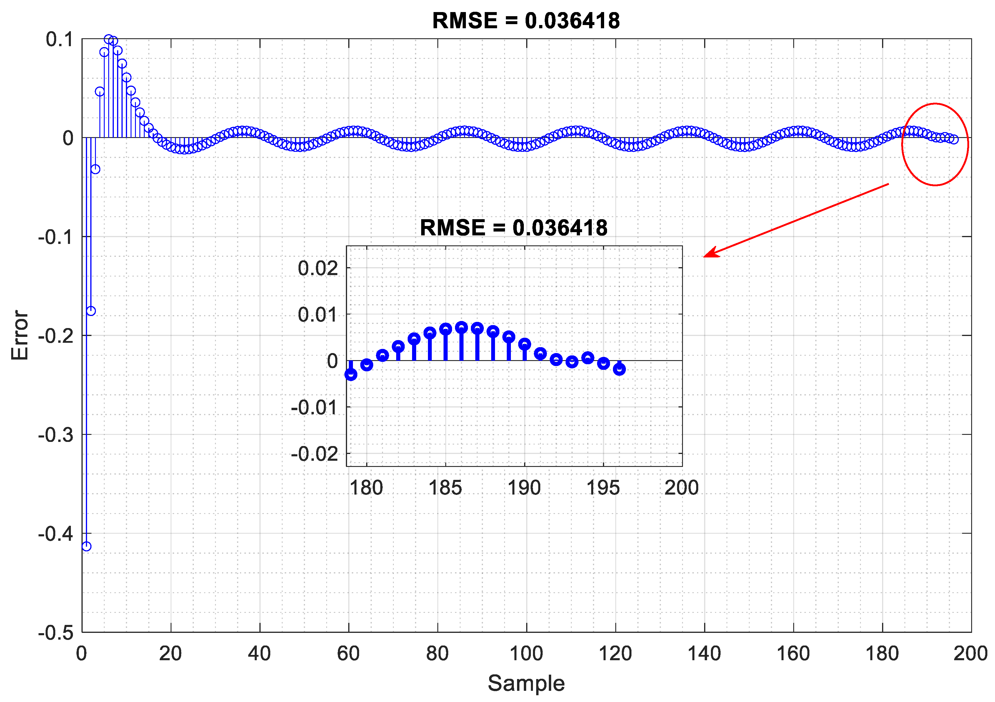
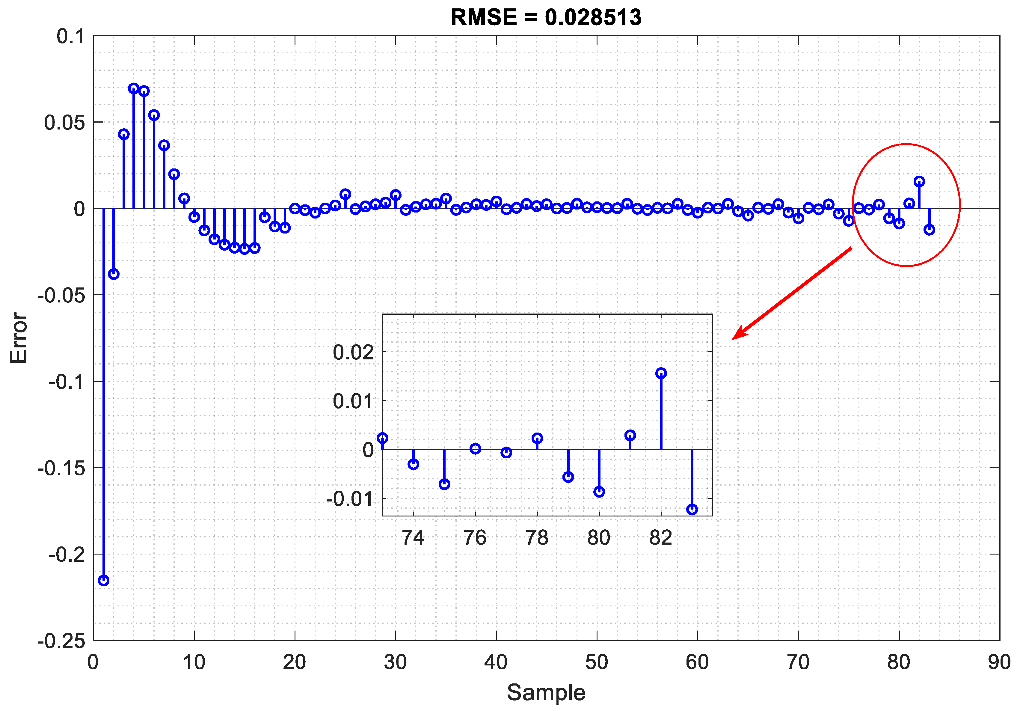
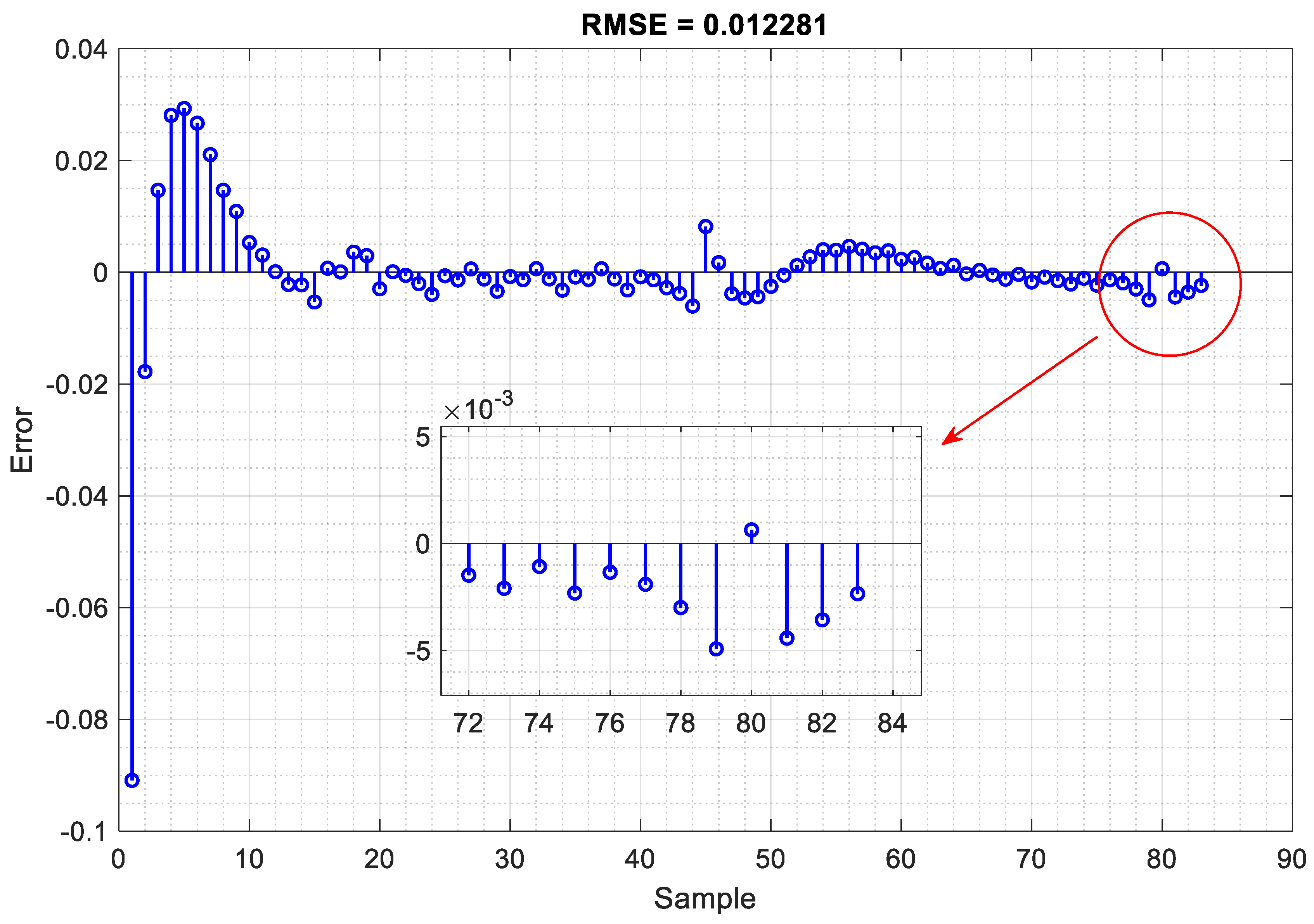
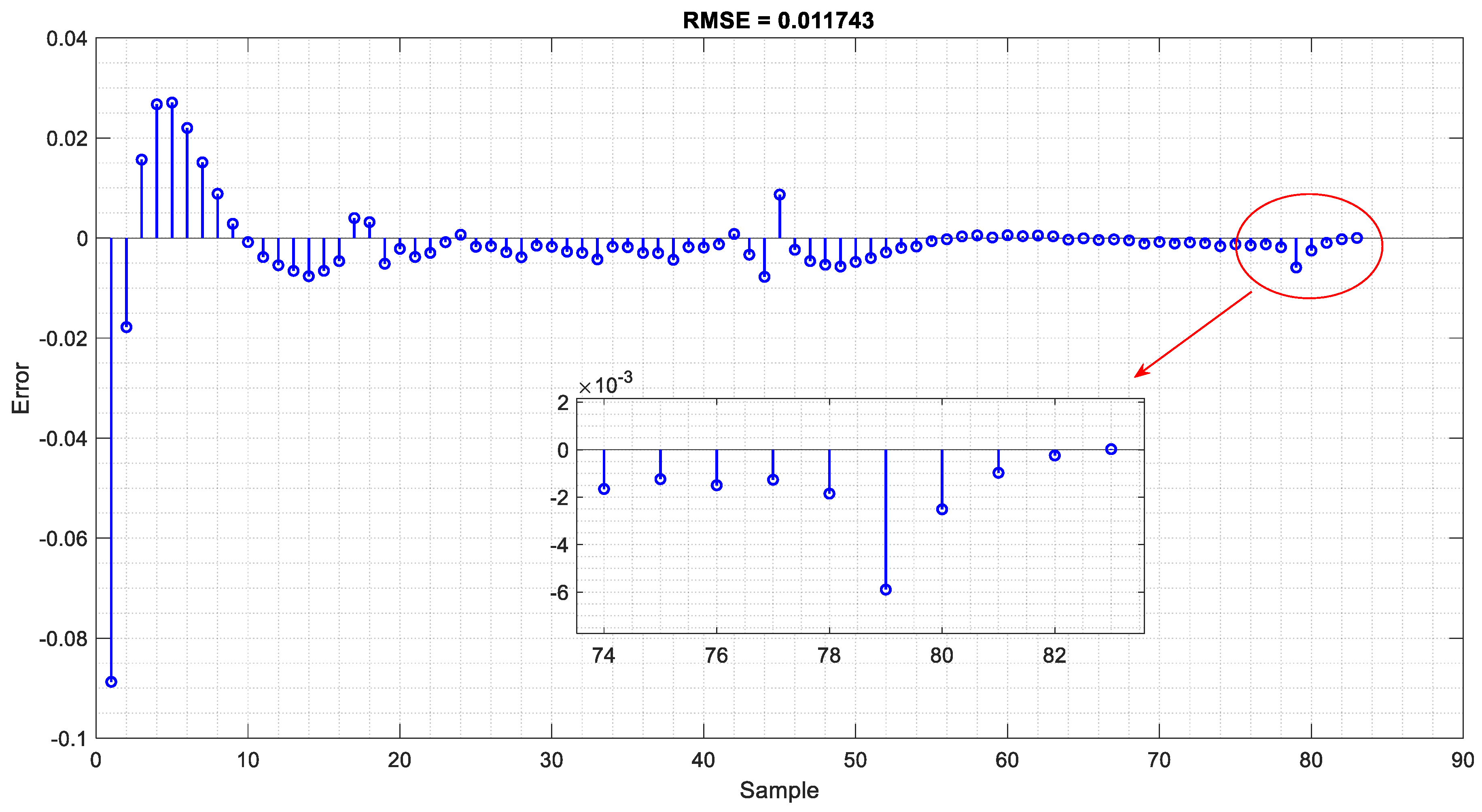
4.2. Training and Verification of the Proposed LSTM Neural Network

The training and verification of the proposed long short-term memory (LSTM) neural network were conducted to ensure its effectiveness in accurately diagnosing faults in the power transformer. A comprehensive dataset, which included various fault scenarios and conditions, was utilized for this purpose. As discussed in the preceding section, a power transformer with specifications (132/33 kV, 63 MVA, 50 Hz) configured as YnD11 was used to validate the proposed inner fault detection methodology. The discussion of the RBSWT-LSTM model’s results is based on testing the model across multiple fault and inrush current scenarios. The model’s performance was evaluated by training it on the proposed deep learning framework, using a total of 2000 cases segregated into four groups: inrush current, internal defects, external faults, and internal faults with CT saturation. The proposed methodology initially extracted features from the differential current using wavelet transform and subsequently computed the mean value of each detail coefficient level of the signals. As previously mentioned, spectral analyses were conducted for each of the four cases, with each case demonstrating unique characteristics, highlighting the effectiveness of the deep learning model in accurately recognizing various fault conditions. The training phase involved feeding the LSTM network with a diverse set of faulted and normal operation signals, allowing the network to learn the underlying patterns and characteristics associated with each condition. The wavelet-decomposed signals, as shown in Figure 11, Figure 12, Figure 13 and Figure 14 were particularly useful in extracting the component levels of the faulted signals, providing the LSTM with detailed information for analysis. During the verification phase, the performance of the LSTM network was rigorously tested against a separate validation dataset. This dataset included signals not previously seen by the network, ensuring an unbiased evaluation of its diagnostic capabilities. The results demonstrated that the LSTM network could accurately identify and classify different types of faults, including external faults, internal faults, inrush currents, and internal faults with CT saturation. Overall, the training and verification process confirmed the robustness and reliability of the proposed LSTM neural network in diagnosing transformer faults, making it a valuable tool for enhancing the protection and monitoring of power systems. In this analysis, MATLAB 2024a programming software is utilized to conduct experiments using data obtained from model tests comprising 2000 cases, each representing a specific type of fault. The collected vibration time-series data were segmented into brief intervals of 0.02 s using the current method. Each segment contained 60 consecutive sample points, with the original time series sampled at a consistent rate of 3 kHz. For this study, the observations were shuffled, and 25% of the observations for each load current were reserved as a validation set for model selection. The analyses in this study are based on a thoroughly researched dataset. The LSTM network, as it gains experience, learns to identify patterns and temporal dependencies within input sequences by adjusting its weights and biases to minimize prediction errors. This capability is facilitated by the unique LSTM architecture, which incorporates cell state mechanisms and gating functions. The model’s outputs are the raw numerical predictions, and the network is trained to make accurate forecasts. The training process spans 200 epochs, with the learning rate gradually decreasing from an initial value of 0.01. By specifying validation data and frequency, the accuracy of the network is verified, and the algorithm continuously assesses the validation data’s accuracy during training. The model’s performance is evaluated using the root mean square error (RMSE) of the predicted values and the proportion of predictions within an acceptable error margin. Figure 15 illustrates the training and analysis of the proposed LSTM network using the Sgdm optimizer. Additionally, Table 4 presents the initial learning rate and associated losses, along with the iteration-wise mini-batch accuracy for both training and validation phases. By the conclusion of the training epochs, the model achieved an RMSE accuracy of 0.039 and a loss accuracy of 1.2 × 10⁻⁴. This comprehensive approach ensures the model’s robustness and accuracy, highlighting the effectiveness of the LSTM network in handling time-series data for fault diagnosis. In this regard, it should be noted that in Figure 15, the dark colors typically correspond to metrics on the training data, while the light colors correspond to metrics on the validation data.
Figure 16, Figure 17, Figure 18 and Figure 19 display the root mean square error (RMSE) indicators comparing the real signals to the predicted signals generated by the LSTM network. These comparisons are made for various signal tests corresponding to different types of faults, all of which are affected by white noise caused by the data measurement units. As observed in these figures, the proposed method demonstrates high accuracy in predicting each type of fault, even with a minimal number of samples. This indicates the robustness and reliability of the LSTM network in handling noisy data and accurately identifying fault conditions.

4.3. Analysis of Results and Comparison with State-of-the-Art Research

As discussed in the previous subsection, the utilization of the proposed Real-Time Boundary Stationary Wavelet Transform (RTBSWT) and the improved long short-term memory (LSTM) networks introduces a novel approach for sequence classification tasks. This approach is particularly effective when the input data contain both spatial and temporal features. Consequently, Table 5 illustrates the capabilities of the proposed framework compared to recent state-of-the-art research in fault detection across various scenarios, including internal faults, external faults, inrush currents, and internal faults coinciding with CT saturation. The proposed method and other recent methods were tested under fair and equal conditions using identical case studies.
The results shown in Table 5 demonstrate that the proposed framework exhibits superior performance. For internal faults, the proposed framework correctly detects 498 out of 500 cases (approximately 99%) with an average detection time of 130 milliseconds. In contrast, other state-of-the-art methods correctly detect 489 out of 500 cases (approximately 97%) but require an average detection time of 340 milliseconds. Regarding external faults, the proposed framework accurately identifies 499 out of 500 cases (approximately 99%) with an average detection time of 110 milliseconds. Meanwhile, other leading methods detect 471 out of 500 cases (approximately 94%) with an average detection time of 310 milliseconds. In the case of inrush currents, the proposed framework successfully detects 497 out of 500 cases (approximately 99%) with an average detection time of 120 milliseconds. Comparatively, other top methods detect 486 out of 500 cases (approximately 97%) with an average detection time of 360 milliseconds. Lastly, for internal faults coinciding with CT saturation, the proposed framework accurately identifies 496 out of 500 cases (approximately 99%) with an average detection time of 170 milliseconds. Other state-of-the-art methods detect 462 out of 500 cases (approximately 92%) with an average detection time of 390 milliseconds. These results highlight the effectiveness and efficiency of the proposed framework, which not only achieves higher detection accuracy but also significantly reduces the detection time compared to other state-of-the-art methods. This demonstrates its potential for real-time applications in fault detection and highlights the advancements made in integrating RBSWT and improved LSTM networks for sequence classification tasks.

5. Conclusions

The research presented in this paper underscores the critical importance of accurate and reliable fault detection in power transformers, essential for maintaining network stability and minimizing operational costs. The novel approach introduced here leverages the RBSWT combined with enhanced long short-term memory (LSTM) networks to address the limitations of existing differential protection schemes, particularly under conditions of CT saturation and measurement uncertainties. Through rigorous testing and validation, the proposed method has demonstrated exceptional performance across various scenarios, including internal faults, external faults, inrush currents, and internal faults coinciding with CT saturation. The empirical results highlight the method’s superiority, achieving higher detection accuracy and significantly reduced detection times compared to recent state-of-the-art techniques. Specifically, the proposed framework achieves approximately 99% accuracy in detecting internal faults, external faults, and inrush currents, with detection times substantially shorter than those of existing methods. These findings confirm the proposed framework’s potential for real-time applications in power transformer fault detection. By effectively integrating RBSWT and LSTM networks, this approach not only enhances fault detection accuracy but also ensures faster response times, which are crucial for the protection and efficient operation of power systems. The advancements presented in this study pave the way for more reliable and cost-effective transformer protection solutions, reinforcing the critical role of innovative technologies in the power sector.

Author Contributions

Conceptualization, Q.A., M.S., S.G.S. and E.M.; Methodology, Q.A., M.S., S.G.S. and E.M.; Software, Q.A.; Validation, Q.A., M.S., S.G.S. and E.M.; Investigation, Q.A., M.S., S.G.S. and E.M.; Data curation, Q.A.; Writing—original draft, Q.A., M.S., S.G.S. and E.M.; Writing—review and editing, Q.A., M.S., S.G.S. and E.M.; Supervision, M.S., S.G.S. and E.M.; Administration, M.S., S.G.S. and E.M. All authors have read and agreed to the published version of the manuscript.

Funding

This research received no external funding.

Data Availability Statement

The data presented in this study can be obtained by sending an email to [email protected]. accessed on 1 September 2024 These data are accessible upon request from the author and will be used in future studies.

Conflicts of Interest

The authors declare no conflicts of interest.

Abbreviations

The following abbreviations are used in this manuscript:
LSTMLong Short-Term MemoryELSTMEnhanced Long Short-Term Memory
RT-SWTReal-Time Stationary Wavelet Transform GRUGated Recurrent Unit
RTBSWTReal-Time Boundary Stationary Wavelet TransformBPTTBackpropagation Through Time
ANN Artificial Neural NetworkSMOTESynthetic Minority Over-Sampling Technique
DNN Deep Neural NetworkRMSERoot Mean Square Error
RNNRecurrent Neural Network

References

  1. Ameli, A.; Ghafouri, M.; Zeineldin, H.H.; Salama, M.M.; El-Saadany, E.F. Accurate fault diagnosis in transformers using an auxiliary current-compensation-based framework for differential relays. IEEE Trans. Instrum. Meas. 2021, 70, 9004214. [Google Scholar] [CrossRef]
  2. Abbasi, A.R. Fault detection and diagnosis in power transformers: A comprehensive review and classification of publications and methods. Electr. Power Syst. Res. 2022, 209, 107990. [Google Scholar] [CrossRef]
  3. Nair, K. Power and Distribution Transformers: Practical Design Guide; CRC Press: Boca Raton, FL, USA, 2021. [Google Scholar]
  4. AlOmari, A.A.; Smadi, A.A.; Johnson, B.K.; Feilat, E.A. Combined approach of LST-ANN for discrimination between transformer inrush current and internal fault. In Proceedings of the 2020 52nd North American Power Symposium (NAPS), Tempe, AZ, USA, 11–13 April 2021; pp. 1–6. [Google Scholar]
  5. He, A.; Jiao, Z.; Li, Z.; Liang, Y. Discrimination between internal faults and inrush currents in power transformers based on the discriminative-feature-focused CNN. Electr. Power Syst. Res. 2023, 223, 109701. [Google Scholar] [CrossRef]
  6. Key, S.; Son, G.-W.; Nam, S.-R. Deep Learning-Based Algorithm for Internal Fault Detection of Power Transformers during Inrush Current at Distribution Substations. Energies 2024, 17, 963. [Google Scholar] [CrossRef]
  7. Chiradeja, P.; Pothisarn, C.; Phannil, N.; Ananwattananporn, S.; Leelajindakrairerk, M.; Ngaopitakkul, A.; Thongsuk, S.; Pornpojratanakul, V.; Bunjongjit, S.; Yoomak, S. Application of probabilistic neural networks using high-frequency components’ differential current for transformer protection schemes to discriminate between external faults and internal winding faults in power transformers. Appl. Sci. 2021, 11, 10619. [Google Scholar] [CrossRef]
  8. Moravej, Z.; Ebrahimi, A.; Pazoki, M.; Barati, M. Time domain differential protection scheme applied to power transformers. Int. J. Electr. Power Energy Syst. 2023, 154, 109465. [Google Scholar] [CrossRef]
  9. Shanu, T.; Mishra, A. Wavelet Scattering and Multiclass Support Vector Machine (WS_MSVM) for Effective Fault Classification in Transformers: A Real-time Experimental Approach. Eng. Res. Express 2024, 6, 035302. [Google Scholar] [CrossRef]
  10. Talware, D.; Kulkarni, D.; Gawande, P.G.; Patil, M.S.; Raut, K.; Mathurkar, P.K. Transformer protection improvement using fuzzy logic. Eur. Chem. Bull. 2023, 12, 54–67. [Google Scholar]
  11. Wong, S.Y.; Ye, X.; Guo, F.; Goh, H.H. Computational intelligence for preventive maintenance of power transformers. Appl. Soft Comput. 2022, 114, 108129. [Google Scholar] [CrossRef]
  12. Guerrero-Sánchez, A.E.; Rivas-Araiza, E.A.; Garduño-Aparicio, M.; Tovar-Arriaga, S.; Rodriguez-Resendiz, J.; Toledano-Ayala, M. A Novel Methodology for Classifying Electrical Disturbances Using Deep Neural Networks. Technologies 2023, 11, 82. [Google Scholar] [CrossRef]
  13. Obakpolor, F.E.; Saha, A.K. Discriminating Between Magnetizing Inrush Current and Fault Current in Power Transformer Protection using Wavelet Transform. In Proceedings of the 2021 Southern African Universities Power Engineering Conference/Robotics and Mechatronics/Pattern Recognition Association of South Africa (SAUPEC/RobMech/PRASA), Potchefstroom, South Africa, 27–29 January 2021; pp. 1–6. [Google Scholar]
  14. Yi, T.; Xie, Y.; Zhang, H.; Kong, X. Insulation fault diagnosis of disconnecting switches based on wavelet packet transform and PCA-IPSO-SVM of electric fields. IEEE Access 2020, 8, 176676–176690. [Google Scholar] [CrossRef]
  15. Babaei, Z.; Moradi, M. Novel method for discrimination of transformers faults from magnetizing inrush currents using wavelet transform. Iran. J. Sci. Technol. Trans. Electr. Eng. 2021, 45, 803–813. [Google Scholar] [CrossRef]
  16. Moosavi, S.M.L.; Damchi, Y.; Assili, M. A new fast method for improvement of power transformer differential protection based on discrete energy separation algorithm. Int. J. Electr. Power Energy Syst. 2022, 136, 107759. [Google Scholar] [CrossRef]
  17. Chavez, J.J.; Popov, M.; López, D.; Azizi, S.; Terzija, V. S-Transform based fault detection algorithm for enhancing distance protection performance. Int. J. Electr. Power Energy Syst. 2021, 130, 106966. [Google Scholar] [CrossRef]
  18. Nazari, A.A.; Hosseini, S.A.; Taheri, B. Improving the performance of differential relays in distinguishing between high second harmonic faults and inrush current. Electr. Power Syst. Res. 2023, 223, 109675. [Google Scholar] [CrossRef]
  19. Ahmadzadeh-Shooshtari, B.; Rezaei-Zare, A. Comparison of harmonic blocking methods in transformer differential protection under GIC conditions. In Proceedings of the 2021 IEEE Electrical Power and Energy Conference (EPEC), Toronto, ON, Canada, 22–31 October 2021; pp. 498–503. [Google Scholar]
  20. Baiceanu, F.; Beniuga, O.; Beniuga, R.; Diac, E. Quality Assessment of Power Transformers Differential Protection Behavior Using Harmonic Restraint Techniques. In Proceedings of the 2020 International Conference and Exposition on Electrical and Power Engineering (EPE), Iasi, Romania, 22–23 October 2020; pp. 680–684. [Google Scholar]
  21. Hamilton, R. Analysis of transformer inrush current and comparison of harmonic restraint methods in transformer protection. IEEE Trans. Ind. Appl. 2013, 49, 1890–1899. [Google Scholar] [CrossRef]
  22. Guzmán, A.; Fischer, N.; Labuschagne, C. Improvements in transformer protection and control. In Proceedings of the 2009 62nd Annual Conference for Protective Relay Engineers, College Station, TX, USA, 30 March–2 April 2009; pp. 563–579. [Google Scholar]
  23. Vazquez, E.; Mijares, I.I.; Chacon, O.L.; Conde, A. Transformer differential protection using principal component analysis. IEEE Trans. Power Deliv. 2007, 23, 67–72. [Google Scholar] [CrossRef]
  24. Li, Z.; Jiao, Z.; He, A. Dynamic differential current-based transformer protection using convolutional neural network. CSEE J. Power Energy Syst. 2022, 1–15. [Google Scholar] [CrossRef]
  25. Hosseinimoghadam, S.M.S.; Dashtdar, M.; Dashtdar, M. Improving the differential protection of power transformers based on clarke transform and fuzzy systems. J. Control. Autom. Electr. Syst. 2022, 33, 610–624. [Google Scholar] [CrossRef]
  26. Peng, F.; Gao, H.; Huang, J.; Guo, Y.; Liu, Y.; Zhang, Y. Power differential protection for transformer based on fault component network. IEEE Trans. Power Deliv. 2023, 38, 2464–2477. [Google Scholar] [CrossRef]
  27. Silva, A.F.; Silveira, E.G.; Alipio, R. Artificial neural network applied to differential protection of power transformers. J. Control Autom. Electr. Syst. 2021, 33, 850–857. [Google Scholar] [CrossRef]
  28. Medeiros, R.P.; Costa, F.B.; Silva, K.M.; Muro, J.D.J.C.; Júnior, J.R.L.; Popov, M. A clarke-wavelet-based time-domain power transformer differential protection. IEEE Trans. Power Deliv. 2021, 37, 317–328. [Google Scholar] [CrossRef]
  29. Suliman, M.Y.; Al-Khayyat, M.T. Discrimination Between Inrush and Internal Fault Currents in Protection Based Power Transformer using DWT. Int. J. Electr. Eng. Inform. 2021, 13, 1–20. [Google Scholar] [CrossRef]
  30. Kumar, V.; Magdum, P.; Lekkireddy, R.; Shah, K. Comprehensive Approaches for the Differential Protection of Power Transformers Using Advanced Classification Techniques. In Proceedings of the 2024 IEEE/IAS 60th Industrial and Commercial Power Systems Technical Conference (I&CPS), Las Vegas, NV, USA, 19–23 May 2024; pp. 1–7. [Google Scholar]
  31. Xiaojun, L.; Feng, X.; Wang, X.; Li, Z. New Method of Transformer Differential Protection Based on Graph Fourier Transform. Electr. Power Compon. Syst. 2023, 51, 1251–1265. [Google Scholar] [CrossRef]
  32. Bagheri, S.; Safari, F.; Shahbazi, N. Detection and Classification of Cross-Country Faults, Internal and External Electrical Faults and Inrush Current in Power Transformers Using Maximum Overlap Discrete Wavelet Transform. J. Nonlinear Syst. Electr. Eng. 2022, 8, 117–137. [Google Scholar]
  33. Shahbazi, N.; Bagheri, S.; Gharehpetian, G. Identification and classification of cross-country faults in transformers using K-NN and tree-based classifiers. Electr. Power Syst. Res. 2022, 204, 107690. [Google Scholar] [CrossRef]
  34. Costa, F.; Souza, B.; Brito, N. Real-time detection of voltage sags based on wavelet transform. In Proceedings of the 2010 IEEE/PES Transmission and Distribution Conference and Exposition: Latin America (T&D-LA), Sao Paulo, Brazil, 8–10 November 2010; pp. 537–542. [Google Scholar]
  35. Costa, F.B. Fault-induced transient detection based on real-time analysis of the wavelet coefficient energy. IEEE Trans. Power Deliv. 2013, 29, 140–153. [Google Scholar] [CrossRef]
  36. Costa, F.B. Boundary wavelet coefficients for real-time detection of transients induced by faults and power-quality disturbances. IEEE Trans. Power Deliv. 2014, 29, 2674–2687. [Google Scholar] [CrossRef]
  37. Rawat, W.; Wang, Z. Deep convolutional neural networks for image classification: A comprehensive review. Neural Comput. 2017, 29, 2352–2449. [Google Scholar] [CrossRef]
  38. Bagheri, M.; Zollanvari, A.; Nezhivenko, S. Transformer fault condition prognosis using vibration signals over cloud environment. IEEE Access 2018, 6, 9862–9874. [Google Scholar] [CrossRef]
  39. Bifet, A.; Gavalda, R.; Holmes, G.; Pfahringer, B. Machine Learning for Data Streams: With Practical Examples in MOA. MIT Press: Cambridge, MA, USA, 2023. [Google Scholar]
  40. Gori, M.; Betti, A.; Melacci, S. Machine Learning: A Constraint-Based Approach; Elsevier: Amsterdam, The Netherlands, 2023. [Google Scholar]
  41. Jordan, M.I. Attractor dynamics and parallelism in a connectionist sequential machine. In Artificial Neural Networks: Concept Learning; IEEE Press: Piscataway, NJ, USA, 1990; pp. 112–127. [Google Scholar]
  42. Espeholt, L.; Agrawal, S.; Sønderby, C.; Kumar, M.; Heek, J.; Bromberg, C.; Gazen, C.; Carver, R.; Andrychowicz, M.; Hickey, J. Deep learning for twelve hour precipitation forecasts. Nat. Commun. 2022, 13, 5145. [Google Scholar] [CrossRef] [PubMed]
  43. Fauvel, K.; Lin, T.; Masson, V.; Fromont, É.; Termier, A. Xcm: An explainable convolutional neural network for multivariate time series classification. Mathematics 2021, 9, 3137. [Google Scholar] [CrossRef]
  44. Oruh, J.; Viriri, S.; Adegun, A. Long short-term memory recurrent neural network for automatic speech recognition. IEEE Access 2022, 10, 30069–30079. [Google Scholar] [CrossRef]
Figure 1. Conceptual Model of Proposed Scheme for Real-time internal fault detection of power transformer.
Algorithms 17 00397 g001
Figure 2. Schematic of differential current measurement in a power transformer.
Algorithms 17 00397 g002
Figure 3. Procedure stage of three decomposition levels of DWT.
Algorithms 17 00397 g003
Figure 4. General Structure for Training a Deep Neural Network (RNN).
Algorithms 17 00397 g004
Figure 5. An illustration of a basic RNN unit schematic.
Algorithms 17 00397 g005
Figure 6. Schematic diagram of the power system with the transformer under study.
Algorithms 17 00397 g006
Figure 7. Differential current signal of the power transformer during inrush current under CT saturation condition.
Algorithms 17 00397 g007
Figure 8. Differential current signal of the power transformer during an internal fault without CT saturation effect.
Algorithms 17 00397 g008
Figure 9. Differential current signal of the power transformer during an internal fault under CT saturation condition.
Algorithms 17 00397 g009
Figure 10. Differential current signal of the power transformer during an external fault under CT saturation condition.
Algorithms 17 00397 g010
Figure 11. Various levels of detail coefficients for the differential current signal of a power transformer during inrush current under CT saturation condition.
Algorithms 17 00397 g011
Figure 12. Various levels of detail coefficients for the differential current signal of a power transformer during an internal fault without CT saturation condition.
Algorithms 17 00397 g012
Figure 13. Various levels of detail coefficients for the differential current signal of a power transformer during an internal fault under CT saturation condition.
Algorithms 17 00397 g013
Figure 14. Various levels of detail coefficients for the differential current signal of a power transformer during an external fault under CT saturation condition.
Algorithms 17 00397 g014
Figure 15. (a,b): RMSE and loss function of the predicted values along with the proportion of predictions at each training iteration of the LSTM network.
Algorithms 17 00397 g015
Figure 16. RMSE analysis of a noisy signal test on a power transformer during inrush current under CT saturation condition.
Algorithms 17 00397 g016
Figure 17. RMSE analysis of a noisy signal test on a power transformer during an external fault under CT saturation condition.
Algorithms 17 00397 g017
Figure 18. RMSE analysis of a noisy signal test on a power transformer during an internal fault without CT saturation effect.
Algorithms 17 00397 g018
Figure 19. RMSE analysis of a noisy signal test on a power transformer during an internal fault under CT saturation condition.
Algorithms 17 00397 g019
Table 1. Binary Code for Different types of the fault in power transformer.
Fault TypeBinary Code
Internal faults(0,0)
External faults(0,1)
Inrush current(1,0)
Internal faults and inrush current (under CT saturation)(1,1)
x t : A vector of features, such as S x and W x , extracted from the wavelet transform.
Table 2. Detailed data of understudied power transformer.
Connection of TransformerYnD11
Nominal apparent power (MVA)63
Voltage ratio (kV)132/33
Rated frequency (Hz)50
Percentage impedance (%)10
CT ratio primary side300:5
CT ratio secondary side1200:5
Table 4. Various evaluation criteria utilized during the training of the LSTM network on a single CPU.
EpochIterationTime Elapsed
(hh:mm:ss)
Mini-Batch
RMSE
Mini-Batch
Loss
Base Learning
Rate
1100:00:03191 × 10−218 × 10−11 × 10−2
505000:00:047 × 10−226 × 10−41 × 10−2
10010000:00:053 × 10−24 × 10−41 × 10−2
15015000:00:061 × 10−257 × 10−71 × 10−3
20020000:00:07933 × 10−544 × 10−71 × 10−3
Table 5. Comparison of the accuracy in detecting various fault types between the proposed method and previous state-of-the-art methods.
Fault TypeAnalysis of Correct Diagnosis by Different Methods
[5,24,27][10,25][9,14]Present Method
Internal faultNumber of casesNumber%Number%Number%Number%
50048997476954829649899
Average detection time (ms)340380410130
External faultNumber of casesNumber%Number%Number%Number%
50046993471944639249999
Average detection time (ms)362310510110
Inrush currentsNumber of casesNumber%Number%Number%Number%
50048697477954719449799
Average detection time (ms)360379525120
Internal faults with CT saturationNumber of casesNumber%Number%Number%Number%
50046292420844318649699
Average detection time (ms)390428610170
Disclaimer/Publisher’s Note: The statements, opinions and data contained in all publications are solely those of the individual author(s) and contributor(s) and not of MDPI and/or the editor(s). MDPI and/or the editor(s) disclaim responsibility for any injury to people or property resulting from any ideas, methods, instructions or products referred to in the content.

