1. Introduction
The tractor is the most used machine in agriculture [
1,
2]. However, tractors are often also used in forestry [
3,
4] for various purposes, including forest logging, felling, timber processing and transport [
5]. In forestry, timber hauling to the roadside landing is a relatively difficult, costly and time-consuming activity [
6]. In many parts of the world, felled timber is hauled from the stump to the roadside landing using systems of ground-based transport, referred to as primary or forest transport [
7].
There are several different ways how to haul the felled timber from the stump to the roadside landing by primary transport. Typical representatives of timber primary transport in lowland areas are forwarders [
8,
9] or even adopted tractors, i.e., agricultural tractors with special four-wheeled trailers transporting the felled short timber from the logging site to the roadside landing. Foresters often prefer the use of agricultural tractors and trailers due to very low initial costs, cheap spare parts, easy availability and good maneuverability in a small area [
10].
Agriculture and forestry are traditionally very risky sectors for workers [
11]. In the Czech Republic, 89 heavy accidents with tractors were recorded in the period from 2009–2018, of which 72 were serious and 17 fatal [
12]. In Australia, 87 accidents with tractors were recorded in 1989–1992, of which nearly 80% happened due to tractor overturning and ended with a tractor driver injury. One of the possible causes mentioned was visual conditions such as poor view, obstacles in the driver’s field of vision, etc. Thus, it follows that a good view from the tractor cabin is important for the driver [
13]. Ergonomics of tractor cabins are also very important [
14], particularly the correct height of the seat, which should be adjustable according to the body height of the tractor driver. The fulfillment of the condition is important for adjusting the correct sitting position of the driver, not only for the reason of having the ideal view from the tractor cabin. The driving position is defined as a position taken by the driver at handling a vehicle or mechanical machine to perform a task. It significantly affects the driving comfort and space arrangement in the cabin [
15].
Sight is the most important sensory modality for collecting information [
16]. Critical components for the assessment of visual attention of the driver are visual acuity, contrast sensitivity and peripheral vision [
17]. Visual attention is one of the important physical functions that help the driver perceive traffic situations [
18]. When the driver’s visual attention is deviated from the primary task (driving), driving performance and safety can be affected [
19]. In most undemanding driving situations, drivers let their eyes wander to objects that are not relevant to driving [
20]. Increased visual load (e.g., obstacles in driver’s view) while driving a vehicle reduces the residual capacity of attention available for the detection of peripheral stimuli [
21,
22]. When attention is diverted, the probability of an accident increases. A study of the prevalence of distracting activities connected with serious accidents revealed that one-third of studied accidents were related to distracting activities [
23].
The eye receives information about elements and things occurring around the tractor while driving and also during the performed action. Therefore, the driver’s field of vision is an important factor when driving a motor vehicle. In the international standard ISO 5721, the field of vision is defined as an “area which can be seen by the eye from the position of a sitting operator”. According to the standard, we distinguish a direct field of view given by direct visibility and an indirect field of view by means of mirrors or other visual aids [
24,
25].
There are several methods to assess the driver’s field of view. In 2000, a manual “test of light bulb shadows” was introduced [
26], which was later enhanced by means of light-detecting sensors [
27]. Technological progress and development of virtual reality led to the introduction of a new method that included a magnetic system of motion capture to simulate the driver [
28]. These days, the driver’s field of view can also be determined by using a terrestrial laser scanner directly in the terrain. TLS is currently one of the most progressive methods of obtaining information about objects and phenomena occurring on, above or under the earth’s surface. By means of this technology, users can gain large amounts of data in a very high resolution and within a very short time [
29].
The goal of this research is to assess and evaluate the driver’s field of view in the timber tractor and trailer unit using the state-of-the-art technology of terrestrial laser scanning. The measurements were taken in line with the requirements stipulated in the international standard ISO 5721 [
24,
25].
2. Materials and Methods
Requirements, test procedures and acceptance criteria for the operator’s field of view from the tractor cabin are defined by the international standard ISO 5721, divided into two parts. The first part of the standard ISO 5721-1 defines requirements, test procedures and acceptance criteria for the operator’s field of forward view [
24]. The second part of the standard ISO 5721-2 defines requirements, test procedures and acceptance criteria for the operator’s sideways and rear field of view [
25]. As to the rear view, the second part of the standard counts only with the indirect field of view, i.e., the tractor operator’s view with the help of rear-view mirrors or other visual aids. This is why procedures were applied according to the first part of the standard for the purpose of our measurements, i.e., requirements and procedures for the operator’s field of forward view.
The operator’s field of view was studied in the timber forwarding unit consisting of an agricultural tractor and coupling trailer (
Figure 1). In addition to standard equipment, the tractor model Valtra T 6300 was furnished with a system of swivel steering, together with the swiveling driver’s seat, allowing a rotation of 360°. The rear part of the cabin was equipped with controllers for the hydraulic crane, and similarly, the front part of the cabin with a steering wheel to allow a direction change for driving backward. This system of swivel steering is referred to as TwinTrac by the manufacturer. The connected means of transport was the coupling trailer STS 12T, which serves to haul wood mass, and is a structural unit consisting of supporting frame, axles, sliding drawer to increase usable area, front safety plate, draw bar, stakes and is equipped with the loading hydraulic crane NJ 85V. The coupling tractor trailer, as well as the hydraulic loading crane, were developed and manufactured by STS Prachatice, a.s.
The timber tractor-and-trailer unit was placed in the airport area, which is a testing polygon providing sufficient space that meets all the conditions and requirements for test procedures in determining the field view imposed by the standard. The measurements were taken in two phases. During the first phase, the unit was put up so that the position of the trailer axis was direct, i.e., identical to the tractor axis. During the second phase, the unit was put up into a position in which the position of the trailer axis deviated from the tractor axis by about 35°. The reason for taking two measurements was to identify and evaluate different situations and parameters of the direct operator’s backward view, based on the operational practice when the axis of the coupled trailer changes its position when reversing into the stand, and thus the operator always has different ergonomic conditions as far as the view of the rear working field is concerned.
2.1. Technology and Principle of Measurement
Currently, the operator’s field of view from the tractor cabin is determined or inspected in the already manufactured machine prototype using the method that measures shading by means of a light source. The method consists of the placement of two-point light sources in a precisely determined place in the cabin (prescribed by the standard), which leaves a trail of light on the horizontal plane of the standing tractor. Then, the value of shading is measured, i.e., chords of sectors on the semicircular view with a radius of 12 m that cannot be seen due to the construction parts of the tractor (e.g., roof and side pillars, air supplies, wipers, exhaust silencers, etc.). An alternative method of checking the field of view is the mathematical determination of shading using a given equation. This method is used primarily as an additional test in case the tractor does not meet the prescribed requirements.
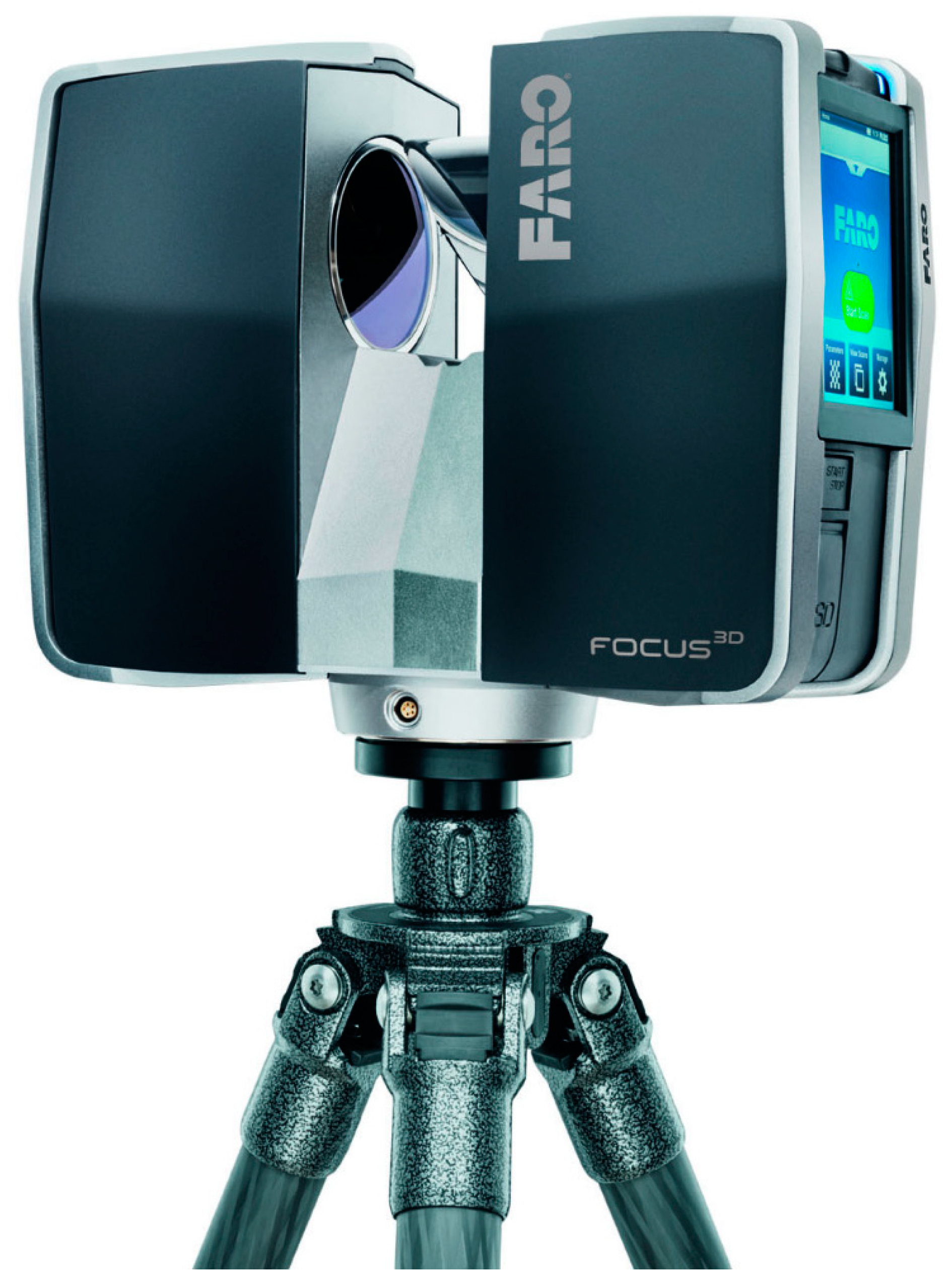
In this study, we employed one of the state-of-the-art methods for 3D data collection using pulse laser technology, which consists of measuring distance based on the calculation of the speed of laser beam pulse reflected from the scanned object—technology of terrestrial laser scanning (TLS). The measuring instrument used for the collection of data was terrestrial high-speed static panoramic scanner FARO Focus 3D (
Figure 2) for detailed measurements whose method of determining the position of individual points, referred to as “Phase-Shift”, measures a phase shift between the constantly transmitted and received beam at a very high speed of recording. Depending on the resolution, the scanning rate can be up to 976,000 points per second. The distance is measured and recorded based on the calculation of the speed of the laser beam pulse reflected from the scanned object. Then, coordinates of individual points are obtained, which are determined by the polar method based on measuring the horizontal and vertical angles and the slant distance [
30]. Thus, a great amount of 3D data of very high accuracy (spatial coordinates) can be obtained by evaluating and processing the measurements, whose output is a graphically spatial illustration of the studied object.
The measurement and recording of data from the used scanner works on the principle of laser beam pulses that are swept by means of a rotating mirror. The measuring range of the instrument for data collection is 360° in the horizontal plane and 305° in the vertical plane. The measured distance can be up to 120 m, which is ten times as much as is necessary for measuring and obtaining data in this study. Thus, the parameters and technical possibilities of the measuring instrument fully meet the requirements and criteria stipulated by the relevant standard for the procedures of measuring the tractor operator’s field of view.
2.2. Procedure of Measuring by Laser Scanner
Prior to the measurement, five targets in the form of white spheres were placed behind a circle segment (r = 12 m). The spheres represented tucking points for the following connection of scanning sites from the position of the left and right eyes. The scanner had to be dislocated in the space of the tractor cabin according to requirements of the standard, which, for tests, stipulates that the point light source has to be installed 680 mm above and 20 mm in front of a so-called seat index point (SIP). A method and the equipment used to determine the position of seat index point (SIP) for machines in agriculture and forestry are defined by the standard ISO 5353 [
31]. Using a tripod, the measuring instrument was then fixed on the seat in the tractor cabin so that the position of the source of laser pulses or the position of the rotating mirror would correspond to the requirements prescribed in the standard. Before the scanning proper, some parameters had to be adjusted, such as the resolution and quality of scanning or spatial extent. Based on experience and published data from previous studies of similar focus [
29], the resolution was set up to 1/4, which provides a high density of focused points. The spacing between the scanned points was approx. 6 mm at a distance of 10 m. The scanning quality (number of control measurements of each point) was set up to a lower value of 2 (max. value for resolution being 8). The reason for selecting this value was primarily time. With the maximum value of quality, the measurements would have taken ca. 40-times longer, which is a huge difference. Nevertheless, even with this lower quality value, the resulting cloud is of high quality and relatively clean, i.e., without noise. Moreover, most points are considered to be removed by means of filtration. The spatial extent was selected as full (values are presented above) due to the need of scanning both forward and backward from the operator’s view. Then, the scanner was moved on the pad in the direction of the connecting line of eyes into the position of the left eye and, when the scanning was finished, also into the position of the right eye. The two positions were axially distant at 65 mm and, at the same time, symmetrically located with respect to the driver’s seat index point.
2.3. Data Processing
The measured data were automatically saved on the inserted SD card and then imported into the SW Faro Scene, which is a part of the package supplied with the scanner. The first step of data processing was the identification of spheres in each scan. The identification was made manually in order to have unambiguous labeling and visual control. Each identified sphere was allocated an actual radius for a more precise coupling of scan pairs. The following step was an automatic registration whose accuracy is given by mean coordinate error and standard deviation. After the registration, manual filtration of points was performed. Points with a height greater than points in the horizontal plane of the terrain and points in this plane representing machines (tractor, trailer) were removed. Then, points at a distance greater than the radius determined for the assessment of the semicircular operator’s view (12 m) were cut off and removed. The last step in the Faro Scene program was to export it into the DXF size (Drawing Exchange Format), which is supported by many special programs, one of which is MicroStation Connect, which was used for further data processing.
2.4. Parameters of the Field of View and Their Evaluation
The output of the processed data is a graphical display of the tractor operator’s field of view on the scheme of the semicircular field. First, layers were created for simpler sorting and saving of individual objects, labels and dimension figures. Then, a vector drawing was made based on the shape of individual parts of the imported cloud of points, illustrating an area visible to the operator. Empty spots represent the shading, i.e., an area that is invisible to the operator. The resulting drawing was divided into a sector of view forward and a sector of view backward. Based on the standard used for the forward view of the operator, the shading was displayed on the semicircular field as a value of the size of chords, which were then provided with dimension figures, and the sector of the view forward was displayed, determined by the extension of semicircular view with a chord length of 9.50 m. The same image of shading was created for the operator’s rear view beyond the standard used. In the field of forward view, the shading is caused by both fixed structural parts of the machine (cabin pillars) and by movable machine parts such as rear view mirrors or wipers. In the case of the rear view, the value of shading depends on the machine or trailer type and equipment (controllers, rear steering wheel, etc.).
The field of rear view was worked out in two variants. The first graphical output represents a field of view from the cabin of the tractor, with the trailer located on the machine (tractor) axis. The second graphic output then represents an operator’s field of view from the cabin of the tractor with the trailer, whose longitudinal axis is turned approximately 35° clockwise from the machine axis. A graphical illustration of the shading of the area inside the semicircular field of forward and rear views was made beyond the standard. Areas shaded by the individual structural parts of the machine (cabin) in percent were color coded. All labels, marks, numerical values and the significance of individual color fields are presented in more detail in the Results.
3. Results
The declared accuracy of the used scanner by the method of static terrestrial laser scanning was two orders higher than required by the standard. The basic parameters of scanner setup (resolution and quality) were chosen based on the above-mentioned study of similar characters [
29]. Both set up parameters guarantee a suitable ratio between the scanning speed and the overall quality of data obtained. Thanks to this resolution, the scanned points create a network of points with a spacing of ca. 7.2 mm at a distance of 12 m from the scanner (distance stipulated by the standard). The spacing is getting smaller proportionally with the decreasing distance; thus, the density of points is increasing, which is important for the creation of a continuous raster and for the subsequent evaluation of shaded or non-shaded areas.
Output from the analysis processed by Bentley graphical software were floor plan schemes of the Valtra T 6300 agricultural tractor with the semicircular segment, the forward view sector (
Figure 3) and the field of rear view (
Figure 4 and
Figure 5), created as an outer extension of the segment of semicircular view with a chord of 9.50 m in length. In the schemes, the chords of shading caused by fixed or movable structural parts of the machine and coupled trailer were provided as dimension figures. Dimensions along the semicircular segment are given in meters with accuracy to centimeters. Unfilled white areas illustrate visible parts of the operator’s (driver’s) view that are projected into the horizontal plane of the terrain. Colored areas represent areas shaded by the external structure (green), the fixed structural elements of the cabin (orange) and the movable structural elements of the machine (blue).
The graphical evaluation of the semicircular field of rear view (
Figure 4 and
Figure 5) shows a shaded area caused by the coupled trailer (violet). Although the given field is qualified as an area of shading, it can be considered a visible area in this case, similar to the unfilled white area, because the operator (driver) has to have a sufficient view of this area and cargo space of the coupled means of transport when performing work activities.
Another output is an overview of the results in the form of tables with legends.
Table 1 presents data on the length and area of shading or unobstructed view of the driver from the machine when looking forward in the travel direction (
Figure 3). The sum of segments (chord lengths) of the driver’s view shading is 5.46 m, which corresponds to 14.85% of the sum of all segments (shading and driver’s view) on a semicircular segment with a radius of 12 m. The shading by fixed machine parts (cabin pillars) is 3.50 m (9.52%) and 1.96 m (5.33%) by movable parts (rear view mirrors and wipers). The total area shaded from the area inside the semicircle with a radius of 12 m (226.19 m
2) is 51.56 m
2, which corresponds to 22.80%, of which the machine itself is shading 26.54 m
2, cabin pillars 18.51 m
2 and movable parts 6.51 m
2. The area of the driver’s view is 174.63 m
2, i.e., 77.21% of the total area.
The standard ISO 5721-1 [
24] stipulates that shading must not be greater than 700 mm, with the exception of shading outside the sector of the forward view. In this field, shading is admissible up to 1500 mm, only in the case that the parts causing it cannot be placed otherwise. There must not be more than six shadings in the semicircular view, and only a maximum of two shadings can be in the sector of view forward. If the shading of structural elements is greater than 80 mm, the gap between the elements must be at least 2200 mm. The results of our study show that requirements concerning the shading of the forward view are fully met. As to the requirements outside the forward view sector, there is a minor collision with the standard. The length of shading by the right pillar of the cabin is exceeded by 200 mm. This fact can be caused by a slight deflection of the driver’s seat inside the cabin due to its permanent loading during work operations and the related placement of the scanner toward the seat index point (SIP). The total number of shadings caused by a part of the wiper arm is also exceeded. Although the shading is negligible, the condition for the arrangement of adjacent structural elements is not met in this case, as a gap between them must not be smaller than 2200 mm. With the use of the method of two light sources, this shading would apparently be neither obvious at plotting, nor measurable, due to the small size of the structural element.
Table 2 and
Table 3 give similar data as
Table 1, but the values are determined for the operator’s rear view, i.e., when working in the terrain.
Table 2 presents the results of scanning with the coupled trailer, placed in the longitudinal machine axis, see
Figure 4, while the data in
Table 3 were obtained from the scanning of the coupled trailer rotated by 35° from the longitudinal machine axis, see
Figure 5. The shading of the driver’s rear view on the semicircular segment with a radius of 12 m is 17.11 m (45.68%) for the trailer in the position of longitudinal machine axis and 15.81 m (42.43%) for the trailer rotated by 35° from the longitudinal machine axis. An unobstructed view of the semicircle is 20.35 m, which is 54.32% of the sum of all segments of the view or 21.45 m (57.57%). In the second case, the overall shading is 1.1 m smaller. This is given by the fact that a part of the trailer is hidden behind the cabin pillar when the trailer is turned.
The shaded area for the first position of the trailer is 116.29 m, which is 51.37% of the total area inside the semicircle. In addition to the machine itself and fixed parts such as cabin pillars and wiper posts, there are also movable parts (rear glass wiper and steering wheel with the handrail) that partly obstruct the driver’s view. Nevertheless, these movable elements total only 1.39 m2, i.e., 0.61% of the overall area. The coupled trailer represents a shading of 43.69 m2 (19.32%). In the second, rotated position, the trailer shades a smaller area of 39.07 m2 (17.27%), which is again given by the fact that the trailer is partly hidden behind the cabin pillar. In this position, the movable parts of the machine are not shading, as they overlap with the shading by the trailer. Based on the above facts, it is possible to state that when the trailer is turned, the driver has an unobstructed view of a larger area, although the difference is not essential—6.01 m2, i.e., 2.66%.
4. Discussion
The manufacture and operation of tractors for agricultural and forestry purposes are currently conditioned by a number of factors that should be considered by manufacturers in their design. Thanks to new technologies and materials, the shape of tractor cabins is gradually changing, and the machines are getting rounder shapes, which affects their appearance, aerodynamics as well as performance. Nevertheless, the most important aspects are still comfort and safety. An ever greater emphasis is put on cabin ergonomics, both in respect of machine control and in respect of adequate view from the place of the tractor operator. Thus, the constructional solution has to ensure that external elements, internal elements, components and accessories do not obstruct the view more than permitted, e.g., the exhaust is hidden behind the cabin pillar, the number of pillars is reduced or a part of the roof is glazed. Despite all possible improvements and innovations, the human factor still remains the greatest risk. Human failure can be assessed through the identification of limits of human functions, which allows them to adapt to changing situations, e.g., experience, visual capabilities, risky behavior, etc. [
32]. Conditions and factors differ in many respects for driving a tractor whose control is complex and demanding on visual skills. Fatigue due to long working hours, momentary lack of attention or inadequate field of view may result in an accident or tractor overturning [
33]. An unobstructed field of view allows the driver a good view inside and outside and to anticipate and detect obstacles, thus preventing the risk of a possible accident. It also helps the driver maintain a more natural and relaxed position during the long working time [
33].
4.1. Studies with a Similar Focus
There are not many studies dealing with the tractor driver’s field of view. Works close to this topic are usually focused on the physiological characteristics of humans. One of them is a study on the presentation of information in the peripheral field of view. Shimura et al. [
34] examined the utilization of peripheral vision when the tested persons performed search tasks on the PC tablet. Wu et al. [
35] investigated the perception properties of peripheral vision in older persons in reaction to the moving body with respect to traffic safety. The above-mentioned studies included an analysis of characteristics of visual perception without the examination of specific methods for stimulating attention. In contrast, Takahashi [
36] conducted preliminary experiments concerning the effect of presented visual stimulation in the peripheral field of view and confirmed its efficiency in stimulating the driver’s attention.
Methods to determine the field of view were numerous. For example, Ryan et al. [
37] analyzed the driver’s field of view in work operations with the hydraulic crane using a virtual model of human figures of diverse heights. Choi et al. [
38] compared the driver’s field of view determined by means of a digital model of the human body with the methods of point light source and with individual tests of the visibility of six helpers. Gilad and Byran [
33] evaluated the driver’s field of view in three tractor models using an innovative virtual model of the human body.
A study focused directly on the evaluation of machine design solutions in respect of the view from the cabin was published by Zemánek et al. [
29], who dealt with a comparison of the method of terrestrial laser scanning with the method of shadow images cast by two-point light sources from the cabin of tractor Zetor Forterra 150 HD. Thus, they provided specific data on whether the cabin construction meets the parameters of standard ISO 5721.
4.2. Comparison of Methods Measuring the Field of View
Based on the measurements using the TLS technology and the description of the conventional measuring procedure presented in the standard ISO 5721 [
24], the pros and cons of the two methods determining the semicircular driver’s field of view can be assessed. The main pros of the TLS method are the independence of external light conditions and the possibility of fast measurement in the field. The average time of the measurement process does not take more than one hour. It allows us to perform repeated measurements for diverse positions of the machine, its components and implements. The high accuracy of this method facilitates analyzing even small obstacles in the driver’s view, such as wipers, controllers, bundles of electric cables, hydraulic hoses, etc. The method is less demanding on the quality of the surface on which the measurements are taken. The measuring technology can also be used on a surface that is not perfectly smooth and exhibits surface irregularities, i.e., surfaces covered with gravel or grass plots, as in our case.
One disadvantage of the TLS method can be considered the high purchasing price of the measuring instrument. However, this con can be eliminated by ordering the measurements as a service with a specialized institution. Another disadvantage is the high sensitivity of the scanner with scratched and dirty glass in the cabin. A measurement quality problem can also happen when the glass transparency is impaired due to heavy toning or plated foils which protect the cabin against overheating in the summer. Such a treatment of glass will cause worse laser beam transmittance, thus reducing the density of the cloud of points that is important for analyzing visibility. Moreover, the processing of measured results requires adequate software equipment, which allows for performing work operations described in the Materials and Methods.
One of the main advantages of using the method of two-point light sources for the determination of shade images consists of low demands for technical equipment. In this case, the equipment is commonly available. The standard defines that a 12 V light bulb (150 W) can be used as a point light source and common measuring aid. No special software is necessary for evaluation.
One of the disadvantages of the method of two-point light sources is time consumption. The preparation of measurements, installation of measuring equipment and evaluation of shade images can even take a day. Another disadvantage is that the measurements have to be taken under light conditions, which can identify the deepest tone of shading. Therefore, the measurements must be made on a very smooth surface (surface irregularities up to 25 mm per standard meter) with a marked square grid (1 m × 1 m) and in a sufficiently large and closed space, which has to prevent the penetration of external light source. In the described specific conditions (light conditions, sufficiently powerful point light sources, large space), it is similarly difficult to distinguish precisely the deepest shade boundaries in smaller obstacles. This makes the method far less accurate and more prone to errors.
A disadvantage of both of the above-mentioned methods for the determination of the driver’s field of view is the fact that they can be applied only to the manufactured machine. When some shortcomings or inadequate parameters are detected as late as this moment, and a necessary essential change of cabin design is needed, it may be a rather costly problem [
29].
4.3. Request to Extend the Content of the Standard
In line with the standardization of technical regulations determining important parameters or properties of the material, product, component or work procedure, binding regulations, ordinances and directives [
39,
40,
41,
42,
43] and international standards are issued. These standards are detailed qualified regulations which may be referred to by contracting parties in the specification of objects of contracts or by state authorities in their generally binding regulations. Compliance with their content is particularly important for manufacturers. Each type of machine controlled by the sitting operator is subject to requirements of a different standard, e.g., criteria of machine for earth works are defined in ISO 5006, Machines for earth works, Operator’s field of view, Test method and criteria for its implementation [
44]. This regulation specifies a different static test method for the determination and evaluation of the operator’s field of view on a bounding rectangular quadrilateral around the machine and on a circle of radius 12 m for testing the view (VTC).
In our case, we had to comply with the test procedures according to the standard ISO 5721 [
24] for agricultural machines. Pursuant to the standard, a tractor has to be designed and equipped so that its driver has an adequate field of view under all usual conditions relating both to road traffic and work in the field. If we consider operations performed in forest terrains, the content of the standard features is a fundamental deficiency. With respect to the equipment of the tractor and timber transport unit as a whole, it is assumed that the operator performs work actions (reversing, hydraulic crane control, logging, loading, etc.) in the rear part of the tractor cabin, which requires an adequate rear view, not only for the reason of safety but also for the reason of work efficiency and quality. Because of the processing or loading of wood mass, which are common forest operations, it is necessary that the tractor or the whole unit has to reverse into the forest stand. Using the swivel seat and relevant controllers, the operator is able to carry out work tasks in the rear part of the cabin, e.g., crane handling, entering the forest stand without causing damage to adjacent trees, etc. In this case, too, an adequate view must be ensured. The standard has two parts, one for the field of view forward, and one for the field of view to the sides and back. Nevertheless, requirements for the direct view are specified for the forward field of view only. In this regulation, the view to the sides and back is considered only as an indirect view, i.e., with the help of rear view mirrors or other visual aids, such as, for example, a closed circuit of TV cameras.
Requirements for the tractor operator’s field of rear view, i.e., the area that can be seen by the eye from the position of a sitting driver with a direct view of the working area in the rear part of the tractor, are not prescribed by the standard. Logically, the prescribed parameters on the semicircular rear view cannot be measured as they are not established in the standard. This is why the method used to establish the driver’s rear view in this study was used according to the first part of the standard.
It follows from the above that in practice, the rear part of the cabin is used and the need for an adequate operator’s view is just as important as when driving forward, namely when the field of rear view can be influenced by the size and type of trailer or by the position of the hydraulic crane on its front. Thus, it would be worth consideration to prepare a new part of the standard or to complement the existing regulation in which requirements, procedures and criteria for the field of operator’s direct rear view would be established. The ambition of the authors of this study is to deal with the shortcoming and to give a stimulus for the creation of the discussed part of the standard.
5. Conclusions
An unobstructed field of vision allows the driver to have a good view, namely outside, where various obstacles have to be anticipated and detected. If the driver’s view is inadequate, not only will their work performance be affected but also their safety and health at work. By the correct and timely evaluation of possible obstacles, the driver can prevent risk of accident and hence damage to property and health. The hitherto most frequently used practical method for determining the driver’s view has been the method of point light source, in which shadows cast by two such sources placed in the position of the driver’s eyes have to be measured. The method is, however, both time-consuming and demanding on conditions of measurement.
The TLS method for the establishment of the driver’s view is faster, less demanding on measurement conditions and particularly much more accurate. It is able to identify even very small obstacles obstructing the driver’s view that could cause an accident. It is a matter of course that basic scanner parameters have to be set up correctly, and machine windows are clean to provide for the permeability of the laser beam.
Pursuant to procedures stipulated in the standard ISO 5721-1 [
24], the tractor driver’s field of view is assessed according to chords of shading segments on the semicircular field of forward view. However, it has to be taken into account that the measurements were taken on the type of machine, the serial production of which was underway in the 1990s. Test procedures and design requirements were then assessed according to the hitherto valid standard, which was issued as late as 2013. With respect to this fact, and based on the results of this study, it can still be claimed that, except for minor deviations, the machine´s facility meets the requirements defined by the standard.
As the tractor (or other machine) driver performs various demanding work operations, it appears useful to assess the field of view in respect of the shading area inside the semicircular view. The results of this analysis are also publicized and discussed in this paper.
Beyond the above-mentioned standard, we also analyzed the driver’s field of rear view. The evaluation was made the same way as in assessing the field of forward view. The authors were led by the fact that the tractor Valtra T 6300 can also be used for reverse travel with the driver facing the travel direction. This specific activity is allowed by the swiveling driver’s seat and by the second steering wheel installed in the rear part of the cabin. With respect to these circumstances, the analysis was made according to the standard ISO 5721-1 as well. A question remains whether the standard should not be modified or extended with the direct driver’s view backward because such an alternative is not described in the standard.


