Article

Design of Relay Switching to Combat an Eavesdropper in IoT-NOMA Wireless Networks

1
Faculty of Electrical Engineering and Computer Science, VSB-Technical University of Ostrava, 17. Listopadu 2172/15, 708 00 Ostrava, Czech Republic
2
Faculty of Electronics and Communications, Sai Gon University, No. 273 An Duong Vuong Street, 5th District, Hochiminh 700 00, Vietnam
3
Faculty of Electrical and Electronics Engineering, Ton Duc Thang University, No. 19 Nguyen Huu Tho Street, 7th District, Hochiminh 700 00, Vietnam
4
Faculty of Information Technology, Da Lat University, No. 1 Phu Dong Thien Vuong Street, Da Lat 67 0000, Vietnam
*
Author to whom correspondence should be addressed.
Future Internet 2022, 14(3), 71; https://doi.org/10.3390/fi14030071
Submission received: 24 January 2022 / Revised: 17 February 2022 / Accepted: 17 February 2022 / Published: 24 February 2022
(This article belongs to the Special Issue 6G Wireless Channel Measurements and Models: Trends and Challenges)

Abstract

:
The requirements of low latency, low cost, less energy consumption, high flexibility, high network capacity, and high data safety are crucial challenges for future Internet of Things (IoT) wireless networks. Motivated by these challenges, this study deals with a novel design of green-cooperative IoT network, which employed coupled relays consisting of one IoT relay selected for forwarding signals to multiple IoT devices while another IoT relay transmitted jamming signals to an eavesdropper. For flexibility, all IoT nodes were powered by solar energy enough to sustain themselves, in order to consume less energy. To reach low latency, the study adopted the emerging non-orthogonal multiple access technique to serve multiple IoT devices simultaneously. Furthermore, the study adopted the simultaneous wireless information and power transfer technique which transmits wireless data for information processing and energy for energy harvesting. The study sketched a novel transmission block time period framework which plotted how a signal could travel via an individual IoT model. Maximizing the achievable bit-rate of IoT devices was considered to improve network capacity and data safety as well. Aiming at enhancing secrecy performance, a rest IoT relay played a role as a friendly jammer to transmit a jamming signal to an eavesdropper using energy harvested from the power splitting protocol. The results achieved in this study showed that the proposed model satisfied the requirements of future green IoT wireless networks. Derivatives leading to closed-form expressions are presented and verified by simulation results. The investigated results demonstrated that a friendly jammer based on radio frequency and energy harvesting strongly forces the intercept probability performance of the eavesdropper towards one, while outage probability performance of IoT devices towards zero showed that the signal to noise ratio tends to infinity.

1. Introduction

An IoT network deals with massive connections of a variety of objects, i.e., smart things, wearable devices, sensors, etc., through the Internet, for information processing. The massively connected IoT devices are challenging problems because of system performance requirements, i.e., lower latency, higher network capacity, less energy consumption, higher data safety, higher flexibility, higher reliability, etc.
In light of emerging techniques, the non-orthogonal multiple access (NOMA) technique was proposed for green IoT network applications, since the NOMA technique may provide massive connections simultaneously using the spectral sharing method. In the last decade, a number of studies on conventional NOMA-assisted IoT networks were published by academic researchers and networking providers. The pioneering studies examined outage probability, system throughput, ergodic capacity, and secrecy performance. The achieved results proved that the NOMA technique showed a system performance which outperformed the orthogonal multiple access (OMA) technique. NOMA system served multiple IoT devices by a single radio frequency (RF) transmission block [1,2,3]. The NOMA-IoT network employed superposition coding technique at the transmitter to encode the superimposed signals of multiple IoT devices over the same RF transmission block by allocating power multiplexing [4]. The initial signals of different IoT devices over the same RF transmission block at the base station (BS) are separated by allocating different power levels. Allocated power levels are based on the channel state information (CSI) of IoT devices [5]. The BS transmits the superimposed signal to those IoT devices with better CSI at lower transmitting power level. On the contrary, BS allocated high power level to transmit IoT device’s data with poorer CSI [6]. IoT devices employ successive interference cancellation (SIC) mechanism to decode their own message contained in the superimposed signal. The IoT device decodes the message with strongest power allocation (PA) factor by treating the other messages with lower PA factors and additive white Gaussian noise (AWGN) as interference. The IoT device then repeats SIC until detecting it own message successfully.
In the study by [7], the author examined a dual-hop cooperative network with a multi-branch using all participate relay. Overall, relay selection (RS) strategies are in two categories, i.e., single RS and multi-RS as shown in [8,9,10,11,12,13]. For clarity, the authors selected relay based on error rate and energy efficiency ratio [11] or signal to noise ratio (SNR) maximization [13]. The incremental relay led to the achievement of higher spectral efficiency; however, higher hardware cost and complexity [14]. Therefore, this study employed a coupled relay as in [15] which shared its benefits with the multi-relay scheme; however, there was a light incremental hardware cost. This study selects just one relay for forwarding signals, by adopting the decode-and-forward (DF) protocol.
Although there have been significant improvements in the benefits of spectral sharing efficiency, the study of the energy efficiency of NOMA-IoT networks is still at the initial stage. Furthermore, simultaneous wireless information and power transfer (SWIPT) the utility of RF to transfer wireless information and energy to the receiver simultaneously has been shown in many studies. Integration of the SWIPT technique in the NOMA system has been studied from the perspective of outage probability (OP) and energy harvesting (EH) performance [15,16,17,18]. Unfortunately, due to the utility functions of RF signal and broadcast superimposed signal of NOMA system, the wireless signal propagation from transmitter to receiver may be eavesdropped on by an illegitimate device. More specially, physical layer security (PLS) is another crucial challenge to protect legitimate devices from a potential eavesdropper in IoT wireless networks. In [3], the EH at receivers may intercept the threat to secure data propagated between legitimate IoT devices. To improve secrecy performance to the low-powered IoT devices, PLS was introduced as an alternative to the ultra-high complex cryptography algorithm [19]. PLS strategies may enhance the secrecy performance of IoT wireless networks by cooperative IoT relaying [18,20], multi-antenna beamforming [14,21,22,23,24,25], and jamming signal [26,27,28,29,30,31,32,33].
There is a gap for cooperative wireless communication networks to achieve distributed spatial diversity, wider networking coverage, lower energy consumption, and reduced interference [14,22]. Cooperative wireless communication networks were significantly improved by the benefit of RS protocol. RS protocols have been analyzed from classical adaptive diversity combining techniques (e.g., a diversity combiner adds diversified branches until the cumulative output is over a threshold [23,24]). This study also uses RS protocol to propose a new RS strategy enabling for green and secure IoT network.
In particular, a friendly jammer is promising as a PLS strategy to improve data safety by adopting jamming signals to poison illegitimate device [26,27,28,29,30,31,32]. In [30], friendly jammer strategies were employed to enhance the secrecy metric to maximize the secrecy outage probability (SOP) for an eavesdropper. In [31], the OP, of the legitimate devices and the intercept probability (IP) of the eavesdropper was obtained to investigate the impact of the jamming signal. The authors proposed an algorithm to pair source and destination using matching theory with a particular jammer [32]. In contrast, this study adopts the SWIPT protocol. There are two major SWIPT techniques, i.e., time switching (TS) and power slitting (PS). In [34], the authors investigated the wireless-powered cooperative networks with TS and PS protocols. Moreover, Yang et al. [16] investigated the impact of PA factors on the NOMA network with SWIPT. By different scope, this paper investigates the impact of the PS factor on the system performance of IoT networks.
Inspired by the above-mentioned studies, this paper employed the cooperation of a coupled IoT relay, on one hand, to improve OP performance and PLS performance for a green IoT network. To reach these aims, some work was undertaken, which are also the contributions of this paper, such as:
(i)
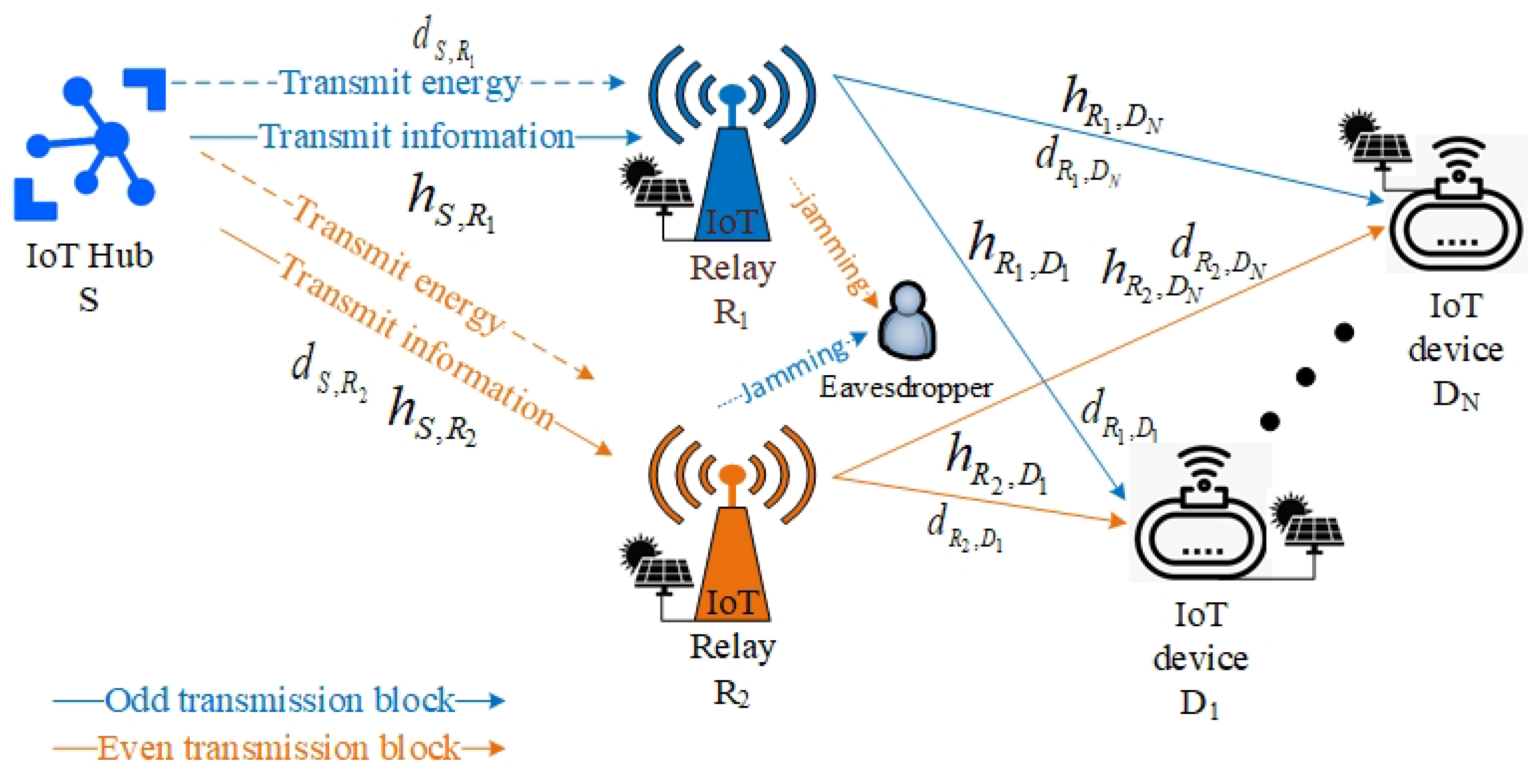
This study designed a green-and-cooperative IoT wireless network, where IoT relays and IoT devices are powered by solar and communicate using RF.
(ii)
To prolong IoT network lifetime, this study adopted SWIPT for EH at coupled relays by applying PS protocol. In particular, the study optimized OP performance of legitimate IoT devices by PS factor optimization in the first-half transmission block time period.
(iii)
In the second-half transmission block time period, the EH at the rest IoT relay intercepts the confidential information being exchanged between legitimate IoT devices. For clarity, the study proposed a selected IoT relay for forwarding signal to legitimate IoT devices using EH while another IoT relay for transmitting jamming signals to illegitimate device using EH as well. In this way, the study reached IP performance at an illegitimate device tending to one.
The rest of the present paper is structured as follows: Section 2 sketches and describes the design of IoT wireless communication models, and follows this by making formulations. Section 3 presents an analysis based on the proposed IoT model and presented the algorithms using for RS strategy and OP investigations. Section 4 presents the analysis and Monte Carlo simulation results. Section 5 concludes the achieved results of the study.

2. System Model and Formulation

Inspired by the study by [30], this study sketches a green-cooperative IoT wireless network, as shown in Figure 1 consisting of an IoT hub S, a coupled IoT relay, and the number of N IoT devices. Assuming all IoT nodes have been solar-powered enough for their operation and equipped with a single antenna. The study employed coupled IoT relays R 1 and R 2 to assist IoT devices. The coupled IoT relays adopted the DF protocol for forwarding superimposed signals to IoT devices. To prolong IoT network online time, the study employed the SWIPT technique with the PS protocol to transmit simultaneously information for information processing and energy for EH at coupled IoT relays. Furthermore, the study proposed an RS strategy to select the relay for the forwarding signal. The selected relay used RF-EH for forwarding the signal instead of its own energy. However, the IoT network as shown in Figure 1 had an eavesdropper E that eavesdropped the IoT relay R 1 or R 2 by wiretapping channel h R 1 , E for odd transmission block or h R 2 , E for even transmission block since the broadcast function of RF. Therefore, the study proposed the rest IoT relay to transmit the jamming signals to the eavesdropper E using RF-EH instead of its own energy. Table 1 shows a comparison of the works in this study, in contrast to previous studies. Please note that the IoT devices D n for n N had distances from IoT hub S as ordered d S , D 1 < < d S , D N .

2.1. Signal Transmission Block Time Period

Observing Figure 1, the IoT network needs two time slots to complete a signal propagation from the transmitter (IoT hub S) to the receivers (IoT device D n for n = N , , 1 ) through coupled IoT relays R 1 and R 2 . For clarity, the study designed a novel transmission block time period diagram as shown in Figure 2. By adopting the SWIPT technique (PS protocol), the IoT hub S transmits including simultaneous energy by power domain λ R r P for EH and superimposed information by remaining power domain 1 λ R r P for information processing at the IoT relay R r , where r = 1 , 2 , λ R r is PS factor and P is power domain at IoT hub S. By the RS strategy as shown in Algorithm 1, only the selected IoT relay is used for forwarding signal to legitimate IoT devices while the other IoT relay is used for transmitting the jamming signal to eavesdropper E. In the second transmission block time, Algorithm 1 switches the selected relay, where variable f l a g is zero and repeats the signal transmission period.
Algorithm 1 Algorithm for switching relay selection
Input: R 1 0 ;
   R 2 1 ;
   t i m e _ p e r i o d r a n d o m 1 : 9 ;
   s e l e c t e d _ r e l a y r a n d o m R 1 , R 2 ;
   f l a g t i m e _ p e r i o d ;
Output: The selected relay forwarded legitimate signals while the other relay transmitted jamming signals.
 1: while true do
 2:    if  f l a g ! = 0  then
 3:      Function_Information_Processing( s e l e c t e d _ r e l a y );
 4:      Function_Forwarding_Signal( s e l e c t e d _ r e l a y );
 5:      Function_Jamming_Signal( ! s e l e c t e d _ r e l a y );
 6:       f l a g f l a g 1 ;
 7:    else
 8:       f l a g t i m e _ p e r i o d ;
 9:       s e l e c t e d _ r e l a y ! s e l e c t e d _ r e l a y ;
10:    end if
11: end while

2.2. Relay Selection Strategy

This study proposed the IoT hub S controlled whole private IoT network. It means that the IoT hub S pre-defined the cooperative script and synchronized the cooperative script to the coupled IoT relays and N devices. Please note that the cooperative script is re-configurable to achieve flexible cooperation.
Algorithm 1 selects which IoT relay ( R 1 or R 2 ) is being selected among coupled relays. For clarity, we first assigned values zero and one for coupled IoT relays R 1 and R 2 , respectively. The study initialized t i m e _ p e r i o d to hold the number of times an IoT relay would be selected for information processing and forwarding legitimate signals to legitimate IoT devices. Variable f l a g is used for counting whether the selected IoT relay forwarded signals enough number of transmission block time period or not. We had a while loop of to ensure the IoT network operated in real-time. We had an if condition to check variable f l a g . There are two cases:
(i)
If variable f l a g is non-zero, it means that an IoT relay has been selected. The selected IoT relay has to process legitimate information and then forward legitimate information after, while the non-selected IoT relay has to transmit a jamming signal. We counted down variable f l a g .
(ii)
If variable f l a g is zero, it means that the selected IoT relay finishing its obligation. Algorithm 1 swaps obligations between IoT relays and resets variable f l a g .
This assumes that the coupled relays own the cooperative script and activated synchronization.

2.3. Formulations

To keep the following simple, the study assumed that variables in Algorithm 1 were assigned initial values as t i m e _ p e r i o d = 1 and s e l e c t e d _ r e l a y = R 1 without losing general properties of Algorithm 1. It is worth noticing that we have sequential block time period T = T ( 1 ) , T ( 2 ) , , + Z + . Since assuming t i m e _ p e r i o d = 1 and s e l e c t e d _ r e l a y = R 1 , we split the set T into two subsets, where T o d d = T ( 1 ) , T ( 3 ) , Z o d d for odd transmission block and T e v e n = T ( 2 ) , T ( 4 ) , Z e v e n for even transmission block.
The EH at the receiver was provided as [36] (Equation (6)) for the PS protocol. From the aforementioned expressions, the EH at the coupled IoT relays in the first phase of the first time slot T 1 o d d T o d d or T 1 e v e n T e v e n , is expressed as follows:
E H S , R 1 T 1 ( o d d ) = η λ R 1 P σ S , R 1 ,
E H S , R 2 T 1 ( o d d ) = η λ R 1 P σ S , R 2 ,
E H S , R 1 T 1 ( e v e n ) = η λ R 2 P σ S , R 1 ,
E H S , R 2 T 1 ( e v e n ) = η λ R 2 P σ S , R 2 ,
where λ R 1 and λ R 2 are the PS factors ( 0 < λ R 1 < 1 in the odd transmission block and 0 < λ R 2 < 1 in the even transmission block), P is power domain at IoT hub S, η is collect factor for 0 η 1 , and expected channel gains σ S , R 1 and σ S , R 2 are given by σ S , R 1 = E h S , R 1 2 and σ S , R 2 = E h S , R 2 2 , respectively.
Furthermore, in the second phase of the first time slot T 1 o d d T o d d or T 1 e v e n T e v e n , in terms of NOMA benefit, the IoT hub S encodes the messages x i for i = N , , 1 of IoT devices and superimposes the messages into the signal by superposition coding and sharing the remaining power domain ( 1 λ R 1 ) P for T 1 o d d or ( 1 λ R 2 ) P for T 1 e v e n with different PA factors α i . Then, the received signals at the IoT relays R 1 and R 2 express as follows:
y R 1 T 1 ( o d d ) = h S , R 1 1 λ R 1 P i = N 1 α i x i + n R 1 ,
y R 2 T 1 ( o d d ) = h S , R 2 1 λ R 1 P i = N 1 α i x i + n R 2 ,
y R 1 T 1 ( e v e n ) = h S , R 1 1 λ R 2 P i = N 1 α i x i + n R 1 ,
y R 2 T 1 ( e v e n ) = h S , R 2 1 λ R 2 P i = N 1 α i x i + n R 2 ,
where n R 1 and n R 2 are AWGN, i.e., n R 1 C N 0 , N 0 and n R 2 C N 0 , N 0 , at IoT relays R 1 and R 2 , respectively. Moreover, h S , R r = g d S , R r ε 2 is channel coefficient from IoT hub S to IoT relay R r ( r = 1 , 2 ), g denoted Rayleigh distribution from IoT hub to coupled IoT relays with g C N 0 , 1 , ε is path-loss exponent, d S , R 1 and d S , R 2 are distances from IoT hub S to IoT relays R 1 and R 2 , respectively. Assuming IoT relays are closed to each other ( d S , R 1 = d S , R 2 ).
From the system model as shown in Figure 1, the devices D 1 and D N are nearest and farthest from the IoT hub S, respectively. In the concept of NOMA, the farthest device D N was allocated the biggest PA factor since the farthest device D N owned poorest CSI. Inspired by studies [21,37], the PA factor α i for i = N , , 1 carried the message x i is given as follows:
α i = i i n = 1 N n n = 1 N n ,
s . t . α N > > α 1 ,
α N + + α 1 = 1 .
In another term of NOMA theory, the SIC mechanism was adopted at coupled IoT relays. Please note that the message x N owned the biggest PA factor α N . The message x N thereby is prioritized SIC first by treating the other messages x j = x 1 , , x N 1 and AWGN n R r as interference. The SIC mechanism repeats until successfully decoded the last message x 1 since it was allocated the smallest PA factor α 1 .
Therefore, signal to interference plus noise ratio (SINR) obtained at the IoT relay R 1 in odd transmission block time period T o d d , when R 1 decoded the message x i ( i = N , , 1 ) by treating the messages x j = x 1 , , x i 1 and AWGN n R 1 as interference, as follows:
(12) γ R 1 x i T 1 ( o d d ) i = N , , 1 = 1 λ R 1 h S , R 1 2 α i ρ 1 λ R 1 h S , R 1 2 ρ j = 1 i 1 α j + 1 , s . t . i > 1 , (13) = 1 λ R 1 h S , R 1 2 α i ρ , s . t . i = 1 ,
where SNR ρ = P N 0 .
Similarly, SINR obtained at the IoT relay R 2 in even transmission block time period T e v e n , when R 2 decoded the message x i ( i = N , , 1 ) by treating the messages x j = x 1 , , x i 1 and AWGN n R 2 as interference, as follows:
(14) γ R 2 x i T 1 ( e v e n ) i = N , , 1 = 1 λ R 2 h S , R 2 2 α i ρ 1 λ R 2 h S , R 2 2 ρ j = 1 i 1 α j + 1 , s . t . i > 1 , (15) = 1 λ R 2 h S , R 2 2 α i ρ , s . t . i = 1 .
An instantaneous bit-rate threshold is achievable after the coupled IoT relays R 1 and R 2 decoded the message x i in the received signal given by (5) for odd transmission block time period T o d d and (8) for even transmission block time period T e v e n as follows:
R R 1 x i T 1 ( o d d ) i = N , , 1 = 1 2 log 2 1 + γ R 1 x i T 1 ( o d d ) i = N , , 1 ,
R R 2 x i T 1 ( e v e n ) i = N , , 1 = 1 2 log 2 1 + γ R 2 x i T 1 ( e v e n ) i = N , , 1 .
Minimum of instantaneous bit-rates at relay R 1 in odd transmission block time period T o d d and relay R 2 in even transmission block time period T e v e n express as follows:
min R R 1 T 1 o d d = min i = N , , 1 R R 1 x i T 1 o d d ,
min R R 2 T 1 e v e n = min i = N , , 1 R R 2 x i T 1 e v e n .
In the second time slot, the IoT relays R 1 for T 2 o d d and R 2 for T 2 e v e n retrieves, re-encodes and forwards the superimposed signals to the IoT devices. There are two feature forwarding protocols (i.e., amplify-and-forward (AF) and DF). This study employed the DF protocol at IoT relays R 1 and R 1 to ensure that R 1 and R 1 received and decoded the messages successfully. After receiving the signals as given by (5) for odd transmission block and (8) for even transmission block, the IoT relays R 1 and R 2 decoded the messages of devices and retrieved the messages and then forwarded them to the devices using the EH as given by (1) for odd transmission block T o d d and (4) for even transmission block T e v e n . The received signal at IoT device D n for n N is expressed as follows:
y D n T 2 ( o d d ) = h R 1 , D n i = N 1 α i E H S , R 1 T 1 ( o d d ) x i + n D n ,
y D n T 2 ( e v e n ) = h R 2 , D n i = N 1 α i E H S , R 2 T 1 ( e v e n ) x i + n D n ,
where n D n is AWGN at the terminal device D n , i.e., n D n C N 0 , N 0 .
IoT device D n also adopted the SIC mechanism to decode its own message x n . By substituting (1) into (20) and (4) into (21), we obtain SINR at device D n for n N when the device D n , respectively, decoded the data symbol x i , where i = N , , n , as follows:
(22) γ D n x i T 2 ( o d d ) i = N , , n = i > 1 h R 1 , D n 2 α i η λ R 1 ρ σ S , R 1 h R 1 , D n 2 η λ R 1 ρ σ S , R 1 j = 1 i 1 α j + 1 , (23) = i = 1 h R 1 , D n 2 α i η λ R 1 ρ S σ S , R 1 ,
where expression (22) is used for IoT device D n ( n > 1 and n N ) while IoT device D 1 has to adopt, respectively, expressions (22) first and then (23) to decode its own message x 1 .
Similarly, the device D n in the even transmission block also adopted the SIC mechanism to decode its own message x n . SINR obtained at device D n for n N when the device D n , respectively, decoded the data symbol x i , where i = N , , n , as follows:
(24) γ D n x i T 2 ( e v e n ) i = N , , n = i > 1 h R 2 , D n 2 α i η λ R 2 ρ σ S , R 2 h R 2 , D n 2 η λ R 2 ρ σ S , R 2 j = 1 i 1 α j + 1 , (25) = i = 1 h R 2 , D n 2 α i η λ R 2 ρ σ S , R 2 ,
where expression (24) is used for IoT device D n ( n > 1 and n N ) while IoT device D 1 has to adopt, respectively, expressions (24) first and then (25) to decode its own message x 1 .
The instantaneous bit-rate threshold is reachable when the IoT device D n decodes the data symbols x i = x N , , x n in odd and even transmission blocks, respectively, as follows:
R D n x i T 2 ( o d d ) i = N , , n = 1 2 log 2 1 + γ D n x i T 2 ( o d d ) i = N , , n ,
R D n x i T 2 ( e v e n ) i = N , , n = 1 2 log 2 1 + γ D n x i T 2 ( e v e n ) i = N , , n .
The minimum of the achievable bit-rate threshold reached at device D n ( n N ) in odd and even transmission blocks, respectively, as follows:
min R D n T 2 o d d = min i = N , , n R D n x i T 2 o d d ,
min R D n T 2 e v e n = min i = N , , n R D n x i T 2 e v e n .
It is the presence of the eavesdropper E as shown in Figure 1. The eavesdropper E eavesdrops the IoT devices by wiretapping channel h R 1 , E for odd transmission block time period T o d d or wiretapping channel h R 2 , E for even transmission block time period T e v e n . To combat eavesdropper E, this study adopted the rest relay as a friendly jammer. Please note that the selected IoT relay and the rest IoT relay in the odd transmission block time period T o d d are IoT relays R 1 and R 2 , respectively. This study proposes the IoT relay R 2 uses the EH as given by (2) to transmit jamming signals to the eavesdropper E. Simultaneously, the eavesdropper E receives the wiretapping signal from the IoT relay R 1 and the jamming signal from the rest IoT relay R 2 in the second time slot T 2 o d d . In contrast, the selected IoT relay and the rest IoT relay in the even transmission block time period T e v e n are IoT relays R 2 and R 1 , respectively. Similarly, the IoT relay R 2 forwards signal using EH as given by (4) while IoT relay R 1 uses the EH as given by (3) to transmit the jamming signal to eavesdropper E. The eavesdropper E receives simultaneously the wiretapping signal from the IoT relay R 2 and the jamming signal from the rest IoT relay R 1 in the second time slot T 2 e v e n .
In odd or even transmission blocks, the received signal at eavesdropper E is expressed as follows:
y E T 2 ( o d d ) = h R 1 , E i = N 1 α i E H S , R 1 T 1 ( o d d ) x i Wiretapping signal + h R 2 , E δ E H S , R 2 T 1 ( o d d ) x ˜ Jamming signal + n E AWGN ,
y E T 2 ( e v e n ) = h R 2 , E i = N 1 α i E H S , R 2 T 1 ( e v e n ) x i Wiretapping signal + h R 1 , E δ E H S , R 1 T 1 ( e v e n ) x ˜ Jamming signal + n E AWGN ,
where n E is AWGN at eavesdropper E with n E C N 0 , N 0 , δ is status of jamming signal. If δ = 0 , the rest IoT relay did not transmit the jamming signal. If δ = 1 , the rest IoT relay transmitted the jamming signal fully by EH as (2) or (4).
From expression (30) for odd transmission block time period, eavesdropper E adopted SIC to detect IoT devices’ message x i = x N , , x 1 . SINR obtained at the eavesdropper E, after the eavesdropper E decoded the data symbol x i ( i = N , , 1 ) as follows:
(32) γ E x i T 2 ( o d d ) i = N , , 1 = i > 1 h R 1 , E 2 α i η λ R 1 ρ σ S , R 1 η λ R 1 ρ h R 1 , E 2 σ S , R 1 j = 1 i 1 α j + h R 2 , E 2 σ S , R 2 + 1 , (33) = i = 1 h R 1 , E 2 α i η λ R 1 ρ σ S , R 1 h R 2 , E 2 η λ R 1 ρ σ S , R 2 + 1 .
Similarly, from expression (31) for even transmission block, eavesdropper E also adopted the SIC mechanism to detect IoT devices’ messages. SINR obtained at eavesdropper E, after the eavesdropper E decoded the data symbol x i ( i = N , , 1 ), as follows:
(34) γ E x i T 2 ( e v e n ) i = N , , 1 = i > 1 h R 2 , E 2 α i η λ R 2 ρ σ S , R 2 η λ R 2 ρ h R 2 , E 2 σ S , R 2 j = 1 i 1 α j + h R 1 , E 2 σ S , R 1 + 1 , (35) = i = 1 h R 2 , E 2 α i η λ R 2 ρ σ S , R 2 h R 1 , E 2 η λ R 2 ρ σ S , R 1 + 1 .
Instantaneous bit-rate threshold is reachable, after the eavesdropper E decoded the data symbols x i = x N , , x 1 in odd or even transmission block, as follows:
R E x i T 2 ( o d d ) i = N , , n = 1 2 log 2 1 + γ E x i T 2 ( o d d ) i = N , , n ,
R E x i T 2 ( e v e n ) i = N , , n = 1 2 log 2 1 + γ E x i T 2 ( e v e n ) i = N , , n ,
where expressions (36) and (37) are with the case the eavesdropper E has wiretapped cooperative transmission script.
In contrast, the selected IoT relay is random and switchable as in Algorithm 1. If the eavesdropper E has no cooperative transmission script, eavesdropper E wiretapped randomly an IoT relay R 1 or R 2 . The expressions (36) and (37) are rewritten as follows:
R E x i T 2 ( o d d ) i = N , , n = 1 4 log 2 1 + γ E x i T 2 ( o d d ) i = N , , n ,
R E x i T 2 ( e v e n ) i = N , , n = 1 4 log 2 1 + γ E x i T 2 ( e v e n ) i = N , , n .

3. System Performance Analysis

The probability density function (PDF) and cumulative distribution function (CDF) of Rayleigh distribution are given by f h 2 x = 1 σ exp x σ and F h 2 x = 1 exp x σ , respectively, where h 2 are random independent variables namely x in PDF and CDF and σ is expected channel gain with σ = E h 2 .

3.1. Outage Probability

Theorem 1.
The outage events at coupled IoT relays R 1 and R 2 occur if the minimum of instantaneous bit-rate thresholds as given by (18) and (19) for, respectively, transmission block time period t = o d d , e v e n could not reach IoT devices’ threshold R . In other words, the OP at IoT relay R r ( r = 1 , 2 ) are given as follows:
O P R r ( t ) = 1 Pr min i = N , , 1 R R r x i T 1 ( t ) R ,
where R is pre-defined IoT devices’ bit-rate threshold.
By applying CDF over Rayleigh distribution, we obtain OP at coupled IoT relays in closed-form as follows:
O P R r t = 1 exp γ 1 λ R r β ρ σ S , R r ,
s . t . β i = α i γ j = 1 i 1 α j , if i > 1 , α 1 , if i = 1 ,
β = min i = N , , 1 β i ,
where SINR threshold γ = 2 2 R 1 , either r = 1 for transmission block t = o d d or r = 2 for transmission block t = e v e n .
Lemma 1.
OP at coupled IoT relays may be improved by equipping multi-antennas at IoT hub S and relays by the number of antennas A S > 1 and A R > 1 , respectively. By adopting transmit antenna selection (TAS) at IoT hub S and selection combining (SC) at coupled relays, OP at coupled IoT relay in multi-input multi-output (MIMO) scenario could be obtained as shown in (A2).
See Appendix A for proof.
From expression (40), the study presents an algorithm for Monte Carlo simulation at IoT relay R r in transmission block t as Algorithm 2.
Algorithm 2 The algorithm for investigation OP at IoT relay R r for r = 1 , 2 in transmission block t = o d d , e v e n
Input: Initialize the parameters as distances d S , R r and d R r , D n ( r = 1 , 2 and n = N , , 1 ), path-loss exponent factor ε , PA factors α i as (9), randomly generate 1 × 10 6 samples for each fading channel over Rayleigh distribution;
Output: Simulation (Sim) results of OP at the relay R r ( r = 1 , 2 ).
   1: Calculate SINR at IoT relay R r by applying (12)–(15);
   2: Calculate achievable bit-rate at IoT relay R r by applying (16) or (17);
   3: Find the minimum of achievable data rate min i = N , , n R R r x i T 1 t by applying (18) or (19);
   4: Initialize variable c o u n t 0 ;
   5: for l = 1 to 1 × 10 6 samples do
   6:    if  min i = N , , 1 R R r x i T 1 ( t ) R  then
   7:       c o u n t c o u n t + + ;
   8:    end if
   9: end for
 10: return OP at the IoT relay R r in transmission block t = o d d , e v e n as given O P R r t = 1 c o u n t c o u n t 10 6 10 6 .
Theorem 2.
The outage event at IoT device D n ( n N ) in transmission block t occurs, on one hand, if IoT relay R r cannot decode at least a message x i ( x i x N , , x n ) in the received signal as (5) for t = o d d or (8) for t = e v e n . On the other hand, if IoT device D n cannot decode at least a message x i ( x i x N , , x n ) in the received signal as (20) for t = o d d or (21) for t = e v e n .
In other words, the OP at IoT device D n in transmission block t is expressed as follows:
O P D n t = 1 Pr min i = N , , n R R r x i T 1 t R , min i = N , , n R D n x i T 2 t R .
By applying CDF, expression (44) has been solved and obtained in closed-form as follows:
O P D n t = 1 exp γ Ω n ,
s . t . ϖ n = min i = N , , n 1 λ R r β i ρ σ S , R r ,
ω n = min i = N , , n β i η λ R r ρ σ S , R r σ R r , D n ,
Ω n = min ϖ n , ω n .
Lemma 2.
Assuming IoT hub S, relay R r and device D n have been equipped by number of antennas A S > 1 , A R > 1 and A D > 1 , respectively. TAS/SC techniques have been employed at transmitter and receiver to select the best signal. As a result, OP at IoT device D n in MIMO scenario is expressed as shown in (A13).
See Appendix B for proof.
From expression (44), the study provides an algorithm for OP Monte Carlo simulation at the IoT device D n as Algorithm 3.
Algorithm 3 Algorithm for investigation OP at IoT device D n in a transmission block t = o d d , e v e n
Input:  Initialize the parameters as in Algorithm 2;
Output:  Simulation (Sim) results of OP at the IoT device D n ;
   1: Calculate SINR at relay R r by applying (12) and (13) for r = 1 or (14) and (15) for r = 2 ;
   2: Calculate achievable bit-rate at relay R r as (16) for r = 1 or (17) for r = 2 ;
   3: Find the minimum of achievable data rate min i = N , , n R R r x i T 1 t ;
   4: Calculate SINR at device D n applying (22) and (23) for t = o d d or (24) and (25) for t = e v e n ;
   5: Calculate achievable bit-rate at device D n by applying (26) for t = o d d or (27) for t = e v e n ;
   6: Find the minimum of achievable data rate min i = N , , n R D n x i T 2 t ;
   7: Initialize variable c o u n t 0 ;
   8: for l = 1 to 1 × 10 6 samples do
   9:    if  min min i = N , , n R R r x i T 1 t , min i = N , , n R D n x i T 2 t R  then
 10:       c o u n t c o u n t + + ;
 11:    end if
 12: end for
 13: return OP at device D n in transmission block t = o d d , e v e n as given O P D n t = 1 c o u n t c o u n t 10 6 10 6 ;

3.2. IP at Eavesdropper

Theorem 3.
The IP event at eavesdropper E in transmission block t refers to IoT relays and devices decoded the messages successfully; however, the eavesdropper E cannot decode the messages successfully. IP at eavesdropper E is expressed as follows:
I P E D n t = 1 Pr min i = N , , n R R r x i T 1 t R , min i = N , , n R E x i T 2 t R .
In other words, expression (49) may be rewritten as follows:
(50) I P E D n t = 1 Pr min min i = N , , n R R r x i T 1 t , min i = N , , n R E x i T 2 t R (51) = Δ 1 Pr min i = N , , n R E x i T 2 t R .
By substituting expressions (16), (17), (36)–(39) into expression (50), we always obtain expression (51) since min i = N , , n R R r x i T 1 t > min i = N , , n R E x i T 2 t .
By applying PDF over Rayleigh distribution, we obtain IP at eavesdropper E in closed-form as follows:
I P E D n t = max i = N , , n 1 α i γ j = 1 i 1 α j σ S , R r σ R r , E α i γ j = 1 i 1 α j σ S , R r σ R r , E + δ γ σ S , R r ¯ σ R r ¯ , E × exp γ λ R r α i γ j = 1 i 1 α j ρ σ S , R r σ R r , E ,
where R r is the selected relay and R r ¯ is the rest relay, δ = 1 if the rest IoT relay sent jamming signal or δ = 0 if the rest IoT relay did not send jamming signal to the eavesdropper E, and SINR threshold in expression (52) is with γ = 2 2 R 1 or γ = 2 4 R 1 for well known or unknown transmission script at eavesdropper E, respectively.
See Appendix C for proof.

3.3. System Throughput Maximization

The IoT network capacity is a crucial factor. The authors analyzed and obtained an ergodic sum rate as shown in [38] (Equation (28)). The authors then obtained the sum of devices’ bit-rate threshold as shown in [38] (Equation (29)). In contrast, this study aims to prove that devices’ bit-rate threshold improves network capacity and enhances secrecy performance as well. In the considered IoT network as shown in Figure 1, the target SINR γ has belonged to the IoT devices’ bit-rate threshold R . From expression OP at IoT device D n as shown in (45) and expression IP at eavesdropper E as shown in (52), this study obtained the maximum of achievable bit-rate threshold R n for IoT device D n ( n > 1 ) as follows:
R n n > 1 = 1 2 log 2 1 + α n j = 1 n 1 α j
By substituting (53) into expressions (45) and (52), the OP at IoT devices and IP at eavesdropper E always tend to one with any SNR ρ since expression (53) given ceiling bit-rate threshold of IoT device D n . It means that IoT devices’ pre-defined bit-rate threshold cannot tend to equal or greater than (53). On the other hand, expression (53) provides achievable maximum data rates for IoT devices in a heterogeneous manner. It means that the IoT devices are served with different throughput leading to unfairness between IoT devices. Therefore, this paper proposes to unify a data rate threshold for all IoT devices as follows:
R = min 1 < n N R n υ ,
where υ factor deals with tolerance for υ 0 . The expression (54) is to ensure all IoT devices could decode their own message successfully and reach the same throughput while SNR ρ .

3.4. PS Factor Optimization and IP Maximization

This paper proposed a unity of IoT devices’ bit-rate threshold as shown in (54) to ensure all IoT devices could decode their own message successfully; however, the eavesdropper E could also eavesdrop and detect IoT devices’ messages. From expressions (45) and (52), the study analyzed that the OP and IP performance may be impacted by the factors, i.e., PA factors α i , SNR ρ , channel gain coefficients, data rate threshold R , and PS factor λ R r , etc. Assuming PA factor α i , channel gain coefficients and SNR ρ are fixed while a unify of IoT devices’ bit-rate threshold is given by (54). Furthermore, the study optimizes PS factor λ R r for r = 1 , 2 .
To optimize the OP and IP performance, this study considers the OP performance at IoT relay R r and OP performance at the farthest device D N is approximate and IP performance at eavesdropper E is maximization. As a result, we exploits the optimal PS factor λ R r for EH at IoT relay R r as follows:
λ R r = 1 max 1 , min n = N , , 1 σ R r , D n σ S , R r .

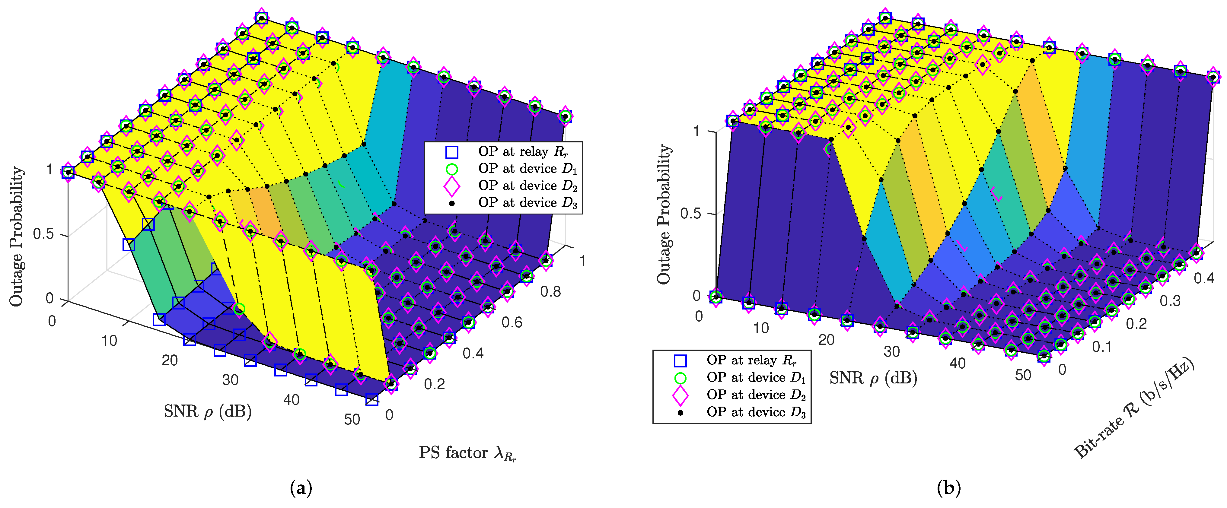
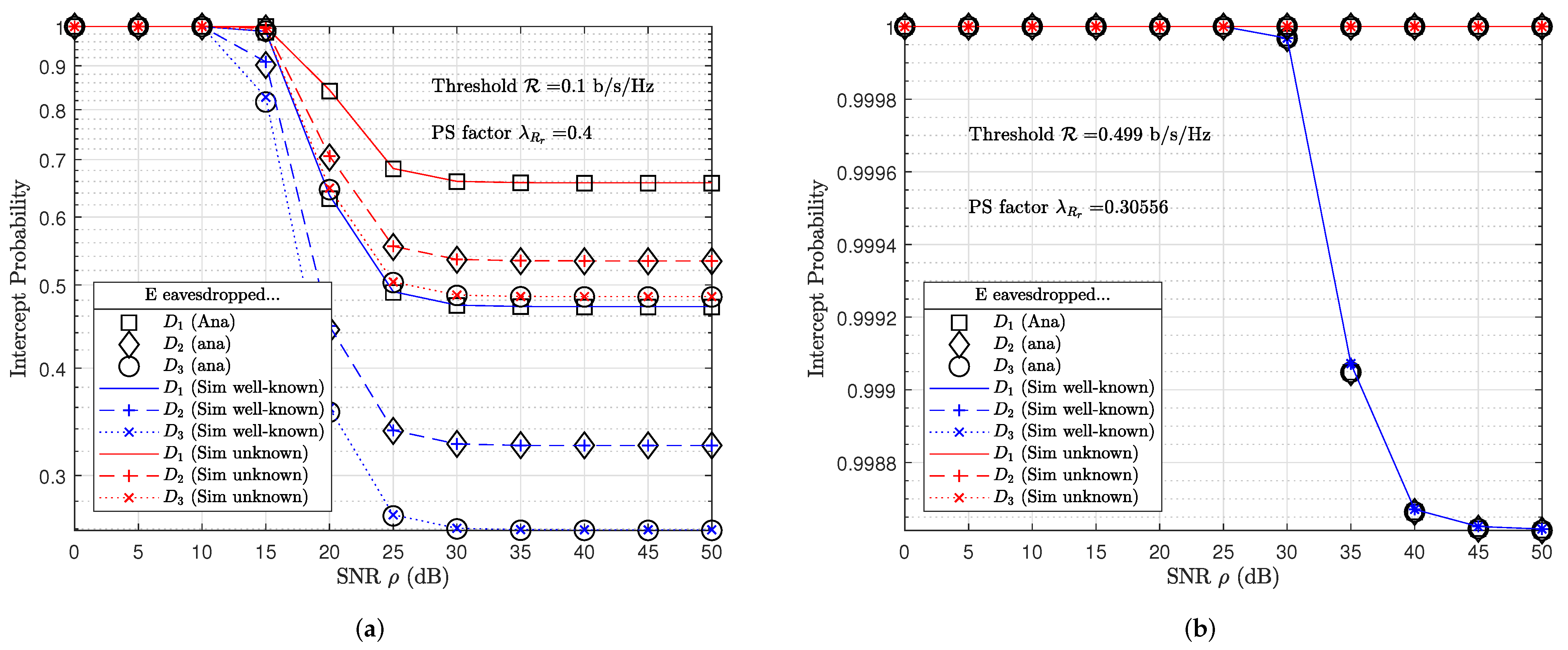
4. Numerical Results

For simplicity, this study assumed the coupled IoT relays are closed to each other. Therefore, the distances from IoT hub S to coupled relays R 1 and R 2 are d R 1 = d R 2 = 10 m. The IoT network shows the number of N = 3 IoT devices. Distances from coupled IoT relays to IoT device D n are equally ( d R 1 , D n = d R 2 , D n for n N ). In this section, the paper conducts the analysis and Monte Carlo simulation results. The outcomes presented in this paper are given by parameters as shown in Table 2.
The study examined the impact of crucial factors, i.e., PS factor λ R r and pre-defined IoT devices’ threshold R . Figure 3a plotted the impact of PS factor λ R r onto OP performance at coupled IoT relays R r and IoT devices by fixed pre-defined bit-rate threshold R = 0.1 b/s/Hz. Allocated unsuitability of PS factor λ R r leads to OP performance at either coupled IoT relays or IoT devices tending to one. On the other hand, Figure 3b also sketched OP performance at coupled IoT relays and IoT devices; however, considering the impact of pre-defined bit-rate threshold R . A lower pre-defined bit-rate threshold R leads to better OP performance ( O P 0 ), however, lower system throughput ( t h r o u g h p u t = 1 O P R ). Observing Figure 3b, it is worth noticing that if the pre-defined bit-rate threshold R < 0.5 b/s/Hz and SNR ρ , the OP at all IoT nodes then tends to zero. on the other hand, if pre-defined bit-rate threshold R 0.5 b/s/Hz, the OP at all IoT nodes then always tends to one since R = 0.5 b/s/Hz is the ceiling bit-rate threshold.
Figure 4a presented OP performance at coupled IoT relays and IoT devices, where fixed pre-defined bit-rate threshold R = 0.1 b/s/Hz and PS factor λ R 1 = λ R 2 = 0.4 . The OP performance of IoT devices are approximate and tend to zero when SNR ρ . Figure 4b also plotted OP performance of coupled IoT coupled relays and IoT devices; however, where pre-defined bit-rate threshold R = 0.499 given by (54) and PS factor λ R r as given by (55). Although OP performance of IoT devices also tended to zero as shown in Figure 4b; however, the OP performance of IoT devices are worse than the obtained results as shown in Figure 4a. Since the pre-defined bit-rate threshold R = 0.499 b/s/Hz in Figure 4b is greater than the pre-defined bit-rate threshold R = 0.1 b/s/Hz in Figure 4a, therefore, SNR in Figure 4b is higher SNR in Figure 4a.
The system throughput results in Figure 5a,b tended to pre-defined bit-rate threshold R when SNR ρ . It is important to notice that IoT devices’ throughput performance reached in Figure 5b is higher IoT devices’ throughput performance reached in Figure 5a since IoT devices’ bit-rate threshold R = 0.499 b/s/Hz is greater than fixed IoT devices’ bit-rate threshold R = 0.1 b/s/Hz.
To verify the potential threat affecting the information propagated on the proposed IoT network, the study investigated the probability that an eavesdropper successfully decoded information from the wiretapping signal as shown in Figure 6. Unfortunately, the results obtained plotted that eavesdropper E has a better probability result than legitimate IoT devices decoding their own proprietary information. In other words, the results shown in Figure 6 are better than those shown in Figure 4a. It is worth explaining cause eavesdropper E has better probability results in decoding information than legitimate IoT devices. Please note that the expression (52) becomes (45), where δ = 0 . In addition, the distance from the eavesdropper E to the IoT relays ( d R r , E = 4 m) is less than the distance from the IoT devices to the IoT relays ( d R r , D 1 = 5 m, d R r , D 2 = 7 m, d R r , D 3 = 12 m). As a consequence, eavesdropper E has channel gain ( σ R r , E = 0.0625 ) that is greater than the channel gains possessed by IoT devices ( σ R r , D 1 = 0.04 , σ R r , D 2 = 0.0204 , σ R r , D 3 = 0.0069 ). Thus, we obtained probability results that eavesdropper E can successfully decode the information better than IoT devices can. In other words I P E D n < O P D n , where δ = 0 and d R r , E < d R r , D n .
In contrast, the major aim of this study is to improve the security of an individual IoT wireless network as shown in Figure 1. There are two cases. In the first case, transmission script is unknown at eavesdropper E. Eavesdropper E randomly selected a received signal (30) or (31) for SIC. In the second case, the transmission script is well-known at eavesdropper E, eavesdropper E selected signal as (30) for SIC in odd transmission block and then signal as (31) for SIC in even transmission block. Figure 7a shows the potential threat when eavesdropper E is able to decode messages of legitimate devices from the wiretapping signal. For example, the eavesdropper E had I P E D n t 0.2 probability to decode message x 3 successfully at SNR ρ = 30 dB. However, IP performance reached I P E D n t 1 approximately at SNR ρ = 30 dB. In particular, the eavesdropper E had just I P E D n t 0.9986 even ρ since the impact of the friendly jamming signal as shown in Figure 7b.

5. Conclusions

Future IoT network requirements have accelerated information propagation rapidly and safely. To satisfy these major aims, the study employed the emerging cooperative NOMA technique and proposed some new solutions, i.e., RS strategy and RF-EH-enabling for forwarding signal and transmitting jamming signal. On one hand, IoT devices’ threshold is defined to maximize throughput performance. On the other hand, the PS factor is also defined to optimize OP and IP as well. Based on the practical model, analysis and simulation results, the study conducted the propositions may provide high network capacity and high reliability to toward next IoT networks. The study is still opening some future tasks such as how Nakagami-m distributions affect OP performance, or how secrecy performance is impacted if eavesdropper equipped multi-antennas.

Author Contributions

T.-N.T., V.-C.H. and T.P.V. delivered main ideas for discussion; V.-C.H. and T.P.V. collected and provided theoretical knowledge about wireless communication techniques to T.-N.T. for analyzing. T.-N.T. and K.N.N.T. designed a system model and formulated its parameters and performance characteristics. T.-N.T. and K.N.N.T. programmed simulations to validate results of the model while V.-C.H. and T.P.V. prepared the manuscript by MS Word. T.-N.T. organized and re-wrote the paper in LaTeX template. M.V. formed initial research ideas and directions, provided supervisions, critically reviewed the organization of the paper and served as a corresponding author. All authors have read and agreed to the published version of the manuscript.

Funding

This research received funding from the Ministry of Education, Youth and Sports within the grant reg. No. SP2021/25 and partially within the Large Infrastructures for Research, Experimental Development and Innovations project reg. No. LM2018140.

Data Availability Statement

Not applicable.

Conflicts of Interest

The authors declare no conflict of interest. The funders had no role in the design of the study; in the collection, analyses, or interpretation of data; in the writing of the manuscript, or in the decision to publish the results.

Appendix A. Proof of Theorem 1

By substituting (1), (4) into (5), (8), respectively, we obtain the received signals at IoT relays R 1 and R 2 in odd and even transmission blocks, respectively. By applying SIC, we obtain an instantaneous bit-rate threshold at coupled IoT relays as shown in (16) and (17). By substituting expression (16) or (17) into expression (40) and after the algebraic transformation, we obtain OP at coupled IoT relays in closed-form by applying PDF over Rayleigh distribution as follows:
O P R r t = 1 Pr h S , R r 2 γ 1 λ R r β ρ = 1 γ 1 λ R r β ρ 1 σ S , R r exp x σ S , R r d x = 1 exp γ 1 λ R r β ρ σ S , R r .
In Lemma 1, this study assumed that IoT hub S has been equipped with the number of antennas A S and coupled IoT relays have been equipped with the number of antennas A R . By employing TAS protocol at IoT hub S, SC protocol at coupled IoT relay as in [15] and applying CDF as given by [21] (Equation (57)), we obtain OP at coupled IoT relays for MIMO scenario as follows:
O P R r t = 1 Pr max A S × A R H S , R r 2 γ 1 λ R r β ρ = ψ = 0 A 1 ψ A ! ψ ! A ψ ! γ 1 λ R r β ρ 1 σ S , R r exp x σ S , R r d x = ψ = 0 A 1 ψ A ! ψ ! A ψ ! exp ψ γ 1 λ R r β ρ σ S , R r ,
where A = A S A R .

Appendix B. Proof of Theorem 2

From (44), OP at IoT device D n is rewritten as follows:
O P D n t = max 1 Pr min i = N , , n R R r x i T 1 t R Z n , 1 Pr min i = N , , n R D n x i T 2 t R Q n .
After the algebraic transformation, expression Z n in (A3) could be obtained by applying PDF given by [21] (Equation (55)) for i > 1 or [21] (Equation (56)) for i = 1 as follows:
Z n = 1 Pr h S , R r 2 γ 1 λ R r β n ρ σ S , R r = 1 γ 1 λ R r β n ρ 1 σ S , R r exp x σ S , R r d x = 1 exp γ 1 λ R r β n ρ σ S , R r ,
s . t . β n = min i = N , , n β i ,
where β i in expression (A5) is given by (42).
By substituting (26) for t = o d d or (27) for t = e v e n into (A3) and applying PDF given by [21] (Equation (55)) for i > 1 or [21] (Equation (56) for i = 1 , expression Q n in (A3) could be obtained as follows:
Q n = 1 Pr h R r , D n 2 γ η λ R r β n ρ σ S , R r = 1 γ η λ R r β n ρ σ S , R r 1 σ R r , D n exp x σ R r , D n d x = 1 exp γ η λ R r β n ρ σ S , R r σ R r , D n ,
where β n in (A6) is given by (A5).
From results presented in study [18], the OP result at IoT device referred to OP result at either IoT relays or IoT device. Therefore, expression (A3) could be rewritten as follows:
O P D n t = max Z n , Q n = 1 exp γ Ω n ,
s . t . ϖ n = min i = N , , n 1 λ R r β i ρ σ S , R r ,
ω n = min i = N , , n β i η λ R r ρ σ S , R r σ R r , D n ,
Ω n = min ϖ n , ω n .
In Lemma 2, IoT hub S, relays and devices have been equipped multiple antennas with A S , A R and A D , respectively. Therefore, expressions Z n and Q n in (A3) are rewritten as follows:
Z n = 1 Pr max A S × A R H S , R r 2 γ 1 λ R r β n ρ = 1 1 ψ = 0 A 1 ψ A ! ψ ! A ψ ! γ 1 λ R r β n ρ 1 σ S , R r exp x σ S , R r d x = ψ = 0 A 1 ψ A ! ψ ! A ψ ! exp ψ γ 1 λ R r β n ρ σ S , R r ,
Q n = 1 Pr max A R × A D H R r , D n 2 γ η λ R r β n ρ σ S , R r = 1 1 ψ = 0 A 1 ψ A ! ψ ! A ψ ! γ η λ R r β n ρ σ S , R r 1 σ R r , D n exp x σ R r , D n d x = ψ = 0 A 1 ψ A ! ψ ! A ψ ! exp ψ γ η λ R r β n ρ σ S , R r σ R r , D n .
By substituting (A11) and (A12) into (A3), we obtain OP at device D n in MIMO scenario as follows:
O P D n t = max Z n , Q n = ψ = 0 A 1 ψ A ! ψ ! A ψ ! exp ψ γ Ω n .
where Ω n is given by (A10) and A = A S A R or A = A R A D if max Z n , Q n = Z n or max Z n , Q n = Q n , respectively.

Appendix C. Proof of Theorem 3

From expression (49), IP at eavesdropper E is rewritten as follows:
I P E D n t = 1 Pr min min i = N , , n R R r x i T 1 t , min i = N , , n R E x i T 2 t R .
After the algebraic transformation, we obtain IP at eavesdropper E as follows:
I P E D n t = 1 min i = N , , n Pr h S , R r 2 γ 1 λ R r β n ρ , Pr h R r , E 2 γ δ η λ R r ρ σ S , R r h R r ¯ , E 2 + 1 η λ R r ρ σ S , R r β n , h R r ¯ , E 2 0 = 1 min γ 1 λ R r β n ρ σ S , R r 1 σ S , R r exp x σ S , R r d x , 0 γ δ η λ R r ρ σ S , R r y + 1 η λ R r ρ σ S , R r β n 1 σ R r , E σ R r ¯ , E exp x σ R r , E y σ R r ¯ , E d x d y = 1 min exp γ 1 λ R r β n ρ σ S , R r K , β n σ S , R r σ R r , E β n σ S , R r σ R r , E + δ γ σ S , R r ¯ σ R r ¯ , E U exp γ η λ R r ρ β n σ S , R r σ R r , E V .
Observing expression (A15), IP at eavesdropper E referred to I P E D n t = 1 min K , U V = 1 U V since the impact of the jamming signal. IP at eavesdropper E then tends to floor I P E D n t = 1 min K , U V = 1 U since V 1 when SNR ρ . The major aim of this study is to improve secrecy performance for IoT network. It means that expression U in (A15) needs to tend to zero ( U 0 ). To reach this aim, the study proposed a pre-defined bit-rate threshold as given (54) and a PS factor as given (55). As a result, the IP at eavesdropper E tended to one approximately at almost SNR as shown in Figure 5b.

References

  1. Qian, L.P.; Feng, A.; Huang, Y.; Wu, Y.; Ji, B.; Shi, Z. Optimal SIC ordering and computation resource allocation in MEC-aware NOMA NB-IoT networks. IEEE Internet Things J. 2018, 6, 2806–2816. [Google Scholar] [CrossRef]
  2. Qian, L.P.; Shi, B.; Wu, Y.; Sun, B.; Tsang, D.H. NOMA-enabled mobile edge computing for Internet of Things via joint communication and computation resource allocations. IEEE Internet Things J. 2019, 7, 718–733. [Google Scholar] [CrossRef]
  3. Jameel, F.; Khan, W.U.; Chang, Z.; Ristaniemi, T.; Liu, J. Secrecy analysis and learning-based optimization of cooperative NOMA SWIPT systems. In Proceedings of the 2019 IEEE International Conference on Communications Workshops (ICC Workshops), Shanghai, China, 20–24 May 2019; pp. 1–6. [Google Scholar]
  4. Liu, M.; Gui, G.; Zhao, N.; Sun, J.; Gacanin, H.; Sari, H. UAV-aided air-to-ground cooperative nonorthogonal multiple access. IEEE Internet Things J. 2019, 7, 2704–2715. [Google Scholar] [CrossRef]
  5. Khan, W.U.; Yu, Z.; Yu, S.; Sidhu, G.A.S.; Liu, J. Efficient power allocation in downlink multi-cell multi-user NOMA networks. IET Commun. 2019, 13, 396–402. [Google Scholar] [CrossRef]
  6. Khan, W.U.; Jameel, F.; Sidhu, G.A.S.; Ahmed, M.; Li, X.; Jäntti, R. Multiobjective optimization of uplink NOMA-enabled vehicle-to-infrastructure communication. IEEE Access 2020, 8, 84467–84478. [Google Scholar] [CrossRef]
  7. Laneman, J.; Wornell, G. Distributed space-time-coded protocols for exploiting cooperative diversity in wireless networks. IEEE Trans. Inf. Theory 2003, 49, 2415–2425. [Google Scholar] [CrossRef] [Green Version]
  8. Sadek, A.K.; Han, Z.; Ray Liu, K.J. A Distributed Relay-Assignment Algorithm for Cooperative Communications in Wireless Networks. In Proceedings of the 2006 IEEE International Conference on Communications, Istanbul, Turkey, 11–15 June 2006; Volume 4, pp. 1592–1597. [Google Scholar]
  9. Bletsas, A.; Khisti, A.; Reed, D.; Lippman, A. A simple Cooperative diversity method based on network path selection. IEEE J. Sel. Areas Commun. 2006, 24, 659–672. [Google Scholar] [CrossRef] [Green Version]
  10. Zhao, Y.; Adve, R.; Lim, T.J. Improving Amplify-and-Forward Relay Networks: Optimal Power Allocation versus Selection. In Proceedings of the 2006 IEEE International Symposium on Information Theory, Seattle, WA, USA, 9–14 July 2006; pp. 1234–1238. [Google Scholar] [CrossRef] [Green Version]
  11. Michalopoulos, D.S.; Karagiannidis, G.K.; Tsiftsis, T.A.; Mallik, R.K. WLC41-1: An Optimized User Selection Method for Cooperative Diversity Systems. In Proceedings of the IEEE Globecom2006, San Francisco, CA, USA, 27 November–1 December 2006; Volume 2006, pp. 1–6. [Google Scholar] [CrossRef]
  12. Madan, R.; Mehta, N.B.; Molisch, A.F.; Zhang, J. Energy-Efficient Cooperative Relaying over Fading Channels with Simple Relay Selection. IEEE Trans. Wirel. Commun. 2008, 7, 3013–3025. [Google Scholar] [CrossRef] [Green Version]
  13. Jing, Y.; Jafarkhani, H. Single and multiple relay selection schemes and their achievable diversity orders. IEEE Trans. Wirel. Commun. 2009, 8, 1414–1423. [Google Scholar] [CrossRef]
  14. Laneman, J.N.; Tse, D.N.; Wornell, G.W. Cooperative diversity in wireless networks: Efficient protocols and outage behavior. IEEE Trans. Inf. Theory 2004, 50, 3062–3080. [Google Scholar] [CrossRef]
  15. Tran, T.N.; Voznak, M. Switchable Coupled Relays Aid Massive Non-Orthogonal Multiple Access Networks with Transmit Antenna Selection and Energy Harvesting. Sensors 2021, 21, 1101. [Google Scholar] [CrossRef] [PubMed]
  16. Yang, Z.; Ding, Z.; Fan, P.; Al-Dhahir, N. The impact of power allocation on cooperative non-orthogonal multiple access networks with SWIPT. IEEE Trans. Wirel. Commun. 2017, 16, 4332–4343. [Google Scholar] [CrossRef] [Green Version]
  17. Tran, T.N.; Voznak, M.; Fazio, P.; Ho, V.C. Emerging cooperative MIMO-NOMA networks combining TAS and SWIPT protocols assisted by an AF-VG relaying protocol with instantaneous amplifying factor maximization. Aeu-Int. J. Electron. Commun. 2021, 135, 153695. [Google Scholar] [CrossRef]
  18. Tran, T.N.; Vo, T.P.; Fazio, P.; Voznak, M. SWIPT Model Adopting a PS Framework to Aid IoT Networks Inspired by the Emerging Cooperative NOMA Technique. IEEE Access 2021, 9, 61489–61512. [Google Scholar] [CrossRef]
  19. Jameel, F.; Wyne, S.; Ding, Z. Secure communications in three-step two-way energy harvesting DF relaying. IEEE Commun. Lett. 2017, 22, 308–311. [Google Scholar] [CrossRef]
  20. Cao, Y.; Zhao, N.; Pan, G.; Chen, Y.; Fan, L.; Jin, M.; Alouini, M.S. Secrecy Analysis for Cooperative NOMA Networks With Multi-Antenna Full-Duplex Relay. IEEE Trans. Commun. 2019, 67, 5574–5587. [Google Scholar] [CrossRef] [Green Version]
  21. Tran, T.N.; Voznak, M. On secure system performance over SISO, MISO and MIMO-NOMA wireless networks equipped a multiple antenna based on TAS protocol. Eurasip J. Wirel. Commun. Netw. 2020, 2020, 11. [Google Scholar] [CrossRef]
  22. Laneman, J.N.; Wornell, G.W. Energy-efficient antenna sharing and relaying for wireless networks. In Proceedings of the 2000 IEEE Wireless Communications and Networking Conference. Conference Record (Cat. No. 00TH8540), Chicago, IL, USA, 23–28 September 2000; Volume 1, pp. 7–12. [Google Scholar]
  23. Yang, H.C.; Alouini, M.S. MRC and GSC diversity combining with an output threshold. IEEE Trans. Veh. Technol. 2005, 54, 1081–1090. [Google Scholar] [CrossRef]
  24. Lioumpas, A.S.; Karagiannidis, G.K.; Tsiftsis, T.A. Adaptive generalized selection combining (A-GSC) receivers. IEEE Trans. Wirel. Commun. 2008, 7, 5214–5219. [Google Scholar] [CrossRef] [Green Version]
  25. Zhao, N.; Wang, W.; Wang, J.; Chen, Y.; Lin, Y.; Ding, Z.; Beaulieu, N.C. Joint Beamforming and Jamming Optimization for Secure Transmission in MISO-NOMA Networks. IEEE Trans. Commun. 2019, 67, 2294–2305. [Google Scholar] [CrossRef] [Green Version]
  26. Li, B.; Qi, X.; Huang, K.; Fei, Z.; Zhou, F.; Hu, R.Q. Security-reliability tradeoff analysis for cooperative NOMA in cognitive radio networks. IEEE Trans. Commun. 2018, 67, 83–96. [Google Scholar] [CrossRef]
  27. Zhou, F.; Chu, Z.; Sun, H.; Hu, R.Q.; Hanzo, L. Artificial noise aided secure cognitive beamforming for cooperative MISO-NOMA using SWIPT. IEEE J. Sel. Areas Commun. 2018, 36, 918–931. [Google Scholar] [CrossRef]
  28. Zhou, F.; Chu, Z.; Wu, Y.; Al-Dhahir, N.; Xiao, P. Enhancing PHY security of MISO NOMA SWIPT systems with a practical non-linear EH model. In Proceedings of the 2018 IEEE International Conference on Communications Workshops (ICC Workshops), Kansas City, MO, USA, 20–24 May 2018; pp. 1–6. [Google Scholar]
  29. Jameel, F.; Wyne, S.; Kaddoum, G.; Duong, T.Q. A comprehensive survey on cooperative relaying and jamming strategies for physical layer security. IEEE Commun. Surv. Tutor. 2018, 21, 2734–2771. [Google Scholar] [CrossRef] [Green Version]
  30. Vilela, J.P.; Bloch, M.; Barros, J.; McLaughlin, S.W. Wireless secrecy regions with friendly jamming. IEEE Trans. Inf. Forensics Secur. 2011, 6, 256–266. [Google Scholar] [CrossRef]
  31. Ding, X.; Song, T.; Zou, Y.; Chen, X. Security-reliability tradeoff for friendly jammer assisted user-pair selection in the face of multiple eavesdroppers. IEEE Access 2016, 4, 8386–8393. [Google Scholar] [CrossRef]
  32. Bayat, S.; Louie, R.H.; Han, Z.; Vucetic, B.; Li, Y. Physical-layer security in distributed wireless networks using matching theory. IEEE Trans. Inf. Forensics Secur. 2013, 8, 717–732. [Google Scholar] [CrossRef]
  33. Lv, L.; Zhou, F.; Chen, J.; Al-Dhahir, N. Secure Cooperative Communications With an Untrusted Relay: A NOMA-Inspired Jamming and Relaying Approach. IEEE Trans. Inf. Forensics Secur. 2019, 14, 3191–3205. [Google Scholar] [CrossRef]
  34. Perera, T.D.P.; Jayakody, D.N.K. Analysis of time-switching and power-splitting protocols in wireless-powered cooperative communication system. Phys. Commun. 2018, 31, 141–151. [Google Scholar] [CrossRef]
  35. Nguyen, N.P.; Duong, T.Q.; Ngo, H.Q.; Hadzi-Velkov, Z.; Shu, L. Secure 5G wireless communications: A joint relay selection and wireless power transfer approach. IEEE Access 2016, 4, 3349–3359. [Google Scholar] [CrossRef]
  36. Lu, X.; Wang, P.; Niyato, D.; Kim, D.I.; Han, Z. Wireless Networks With RF Energy Harvesting: A Contemporary Survey. IEEE Commun. Surv. Tutor. 2015, 17, 757–789. [Google Scholar] [CrossRef] [Green Version]
  37. Tran, T.N.; Voznak, M. Adaptive multiple access assists multiple users over multiple-input-multiple-output non-orthogonal multiple access wireless networks. Int. J. Commun. Syst. 2021, 10, e4803. [Google Scholar] [CrossRef]
  38. Men, J.; Ge, J.; Zhang, C. Performance analysis of nonorthogonal multiple access for relaying networks over Nakagami-m fading channels. IEEE Trans. Veh. Technol. 2016, 66, 1200–1208. [Google Scholar] [CrossRef]
Figure 1. The green-cooperative IoT wireless network.
Futureinternet 14 00071 g001
Figure 2. Power resource allocation with PS factor λ and PA factors α i for i = 1 , , N .
Futureinternet 14 00071 g002
Figure 3. Comparisons of OP at coupled IoT relay R r and IoT devices with (a) fixed pre-defined bit-rate threshold R = 0.1 b/s/Hz versus PS factors λ R r = 0 , , 1 while (b) fixed PS factor λ R r = 0.4 versus pre-defined bit-rate threshold R = 0 , , 0.5 b/s/Hz.
Futureinternet 14 00071 g003
Figure 4. OP performance at IoT relays and devices with (a) fixed PS factor λ R r = 0.4 and fixed bit-rate threshold R = 0.1 , (b) optimized bit-rate threshold and PS factors.
Futureinternet 14 00071 g004
Figure 5. Comparisons of system throughput at IoT devices with (a) fixed PS factor λ R r = 0.4 and fixed bit-rate threshold R = 0.1 , (b) optimized bit-rate threshold and PS factors.
Futureinternet 14 00071 g005
Figure 6. IP performance of cooperative NOMA-IoT network without jamming signal.
Futureinternet 14 00071 g006
Figure 7. IP performance of cooperative NOMA-IoT network with jamming signal, (a) fixed PS factor λ R r = 0.4 and fixed bit-rate threshold R = 0.1 , (b) optimized bit-rate threshold and PS factor.
Futureinternet 14 00071 g007
Table 1. Comparison to the other studies on secrecy performance.
StudiesNumber of RelaysRSNumber of DevicesSWIPTJamming Signal
[21]0no2nono
[18]1no2yesno
[25]0noKnoyes
[20]1no2noyes
[33]1no1noyes
[35]Kyes1yesno
This study2yesNyesyes
Table 2. Table of parameters (denoted r = 1 , 2 ).
Number of devices N = 3
Distances d S , R r = 10  m, d R r , D 1 = 5  m, d R r , D 2 = 7  m, d R r , D 3 = 12  m, d R r , E = 4  m
Path-loss exponent ε = 4
Channel gains σ S , R r = 0.01 , σ R r , D 1 = 0.04 , σ R r , D 2 = 0.0204 , σ R r , D 3 = 0.0069 , σ R r , E = 0.0625
Fixed bit-rate thresholds R = R 1 = R 2 = R 3 = 0.1  b/s/Hz
Optimal bit-rate thresholds R = 0.499  b/s/Hz as given by (54) with tolerance factor for υ = 0.001
Fixed PS factor λ R r = 0.4
PS factor λ R r = 0.3056 as given by (55)
PA factors α 1 = 0.1667 , α 2 = 0.3333 , and α 3 = 0.5 as given by [21,37]
SNRs ρ 0 , , 50  dB
Status of jamming signal δ = 1
Publisher’s Note: MDPI stays neutral with regard to jurisdictional claims in published maps and institutional affiliations.

