Article

Wireless and Fiber-Based Post-Quantum-Cryptography-Secured IPsec Tunnel

by
Daniel Christian Lawo
1,2,
Rana Abu Bakar
3,4,
Abraham Cano Aguilera
1,2,
Filippo Cugini
3,
José Luis Imaña
5,
Idelfonso Tafur Monroy
1,* and
Juan Jose Vegas Olmos
2
1
Department of Electrical Engineering, Eindhoven University of Technology, 5600 MB Eindhoven, The Netherlands
2
Software Architecture, Nvidia Corporation, Yokneam Illit 2066730, Israel
3
Consorzio Nazioinale Interuniversitario per le Telecomunicazioni, 56124 Pisa, Italy
4
Istituto di Telecomunicazioni, Informatica e Fotonica, Scuola Superiore Sant’Anna, 56124 Pisa, Italy
5
Department of Computer Architecture and Automation, Universidad Complutense de Madrid, 28040 Madrid, Spain
*
Author to whom correspondence should be addressed.
Future Internet 2024, 16(8), 300; https://doi.org/10.3390/fi16080300
Submission received: 26 July 2024 / Revised: 15 August 2024 / Accepted: 20 August 2024 / Published: 21 August 2024
(This article belongs to the Special Issue Edge Intelligence: Edge Computing for 5G and the Internet of Things)

Abstract

:
In the near future, commercially accessible quantum computers are anticipated to revolutionize the world as we know it. These advanced machines are predicted to render traditional cryptographic security measures, deeply ingrained in contemporary communication, obsolete. While symmetric cryptography methods like AES can withstand quantum assaults if key sizes are doubled compared to current standards, asymmetric cryptographic techniques, such as RSA, are vulnerable to compromise. Consequently, there is a pressing need to transition towards post-quantum cryptography (PQC) principles in order to safeguard our privacy effectively. A challenge is to include PQC into existing protocols and thus into the existing communication structure. In this work, we report on the first experimental IPsec tunnel secured by the PQC algorithms Falcon, Dilithium, and Kyber. We deploy our IPsec tunnel in two scenarios. The first scenario represents a high-performance data center environment where many machines are interconnected via high-speed networks. We achieve an IPsec tunnel with an AES-256 GCM encrypted east–west throughput of 100 Gbit/s line rate. The second scenario shows an IPsec tunnel between a wireless NVIDIA Jetson and the cloud that achieves a 0.486 Gbit/s AES-256 GCM encrypted north–south throughput. This case represents a mobile device that communicates securely with applications running in the cloud.

1. Introduction

For several years now, quantum computing has been a focal point of rigorous investigation ultimately resulting in the creation of a quantum processor [1]. The arrival of a powerful commercially available quantum computer is expected in the near future, with prototype systems [2], digital annealers [3], and quantum annealers [4] already being on the market. This presents a significant challenge to contemporary communication systems reliant on classical cryptographic infrastructure and methods. The vulnerability of asymmetric cryptography, such as RSA [5], to quantum processors poses a serious threat to our communication. Unlike asymmetric cryptography, symmetric cryptography such as the Advanced Encryption Standard (AES)/Rijndael cipher [6] is said to remain secure against quantum threats if its key size is doubled [7]. Hence, a shift from AES-128 to AES-256 is required. However, the urgency to replace current asymmetric cryptography algorithms with quantum-resistant alternatives, known as post-quantum cryptography (PQC), is paramount. It is imperative to account for the threat to our digital communications posed by the arrival of quantum computers. Therefore, in December 2016, the National Institute of Standards and Technology (NIST) launched a competition for the standardization of new, quantum-resilient algorithms that are hard to crack not only by classical computers but also by quantum computers [8].
Recently, the NIST announced their decision to standardize three PQC signature algorithms and one Key Exchange Mechanism (KEM) [8]. Many different candidates were submitted to the NIST competition. The security of the candidates is mostly based on one of the following approaches [9]: multivariate cryptography, hash-based cryptography, code-based cryptography, isogeny-based cryptography, or lattice-based cryptography. Multivariate cryptographic systems base their security on solving multivariate equation systems. An example for a PQC candidate which is multivariate-based is the PQC signature scheme Rainbow [10]. Hash-based schemes base their security on the well-known and well-understood technique of hashing. The NIST candidate SPHINCS+ [11] is a hash-based signature scheme that was one of the four candidates in the NIST competition that was announced to be standardized. Code-based schemes are relying on algorithmic primitives [12]. To name an example, Classic McEliece [13] is a code-based KEM that was submitted to the NIST competition that was not elected to be standardized. However, three out of four candidates for PQC standardization, namely Falcon [14], Dilithium [15], and Kyber [16], are based on cryptographic lattices. The fourth candidate that is going to be standardized, SPHINCS+ [11], is hash-based. In the literature, extensive comparisons have been made regarding the performance of SPHINCS+, Falcon, and Dilithium. Notably, studies such as [17,18] identify certain drawbacks of SPHINCS+ that are particularly relevant to our work. Specifically, SPHINCS+ produces signatures that are substantially larger in size, as shown in Table 1. These significantly larger signature sizes pose a concern for our client-to-data-center application. Additionally, SPHINCS+ is the most computationally intensive algorithm among the three. Therefore, we have excluded SPHINCS+ from consideration and are focusing our PQC work on three out of the four algorithms that have been chosen for standardization: Falcon [14], Dilithium [15], and Kyber [16].
The current digital technologies confirm identities using digital certificates that create a so-called chain of trust. Figure 1 illustrates how a chain of trust is established using a sequence of certificates, which can include one or multiple intermediate certificates. A digital certificate contains the public key and the signature of a certificate authority (CA). The end-entity certificate includes the certificates within the certificate chain. Therefore, the sizes of the signatures and the public keys heavily influence the size of the resulting certificate. Naturally, that holds true for all certificates included in the certificate chain that need to be validated by the end entity. In Table 1, the signature and public key sizes of the three PQC signature algorithms chosen by the NIST are shown in bytes. Additionally, Kyber’s public key and encapsulation sizes in bytes can be seen. For reference purposes, Table 2 shows the sizes in bytes for the most commonly used classical signature algorithms. The signature algorithms mentioned in Table 2 are not quantum-safe. Comparing Table 1 with Table 2 shows clearly that the sizes of the PQC algorithms are significantly greater compared to their classical counterparts. Hence, the size of a PQC certificate is considerably greater than the size of a certificate that is signed using classical cryptographic algorithms such as RSA. While PQC algorithms have yet to be standardized and rolled out into production systems, efforts are being taken to examine so-called hybrid certificates [19,20]. Hybrid certificates are certificates that support the use of multiple algorithms during the transitional phase where classical algorithms are still in use and PQC algorithms are being deployed.
For the transition towards the use of quantum-resilient algorithms, PQC must be integrated into existing protocols that are used nowadays such as Internet Protocol security (IPsec). Our work contributes to the goal of integrating PQC into the widely established IPsec protocol. In this work, we use the reference implementations of Falcon, Dilithium, and Kyber that were submitted to the NIST competition. We do not use an optimized, accelerated, or in any form modified version of the algorithms. We benchmark the PQC algorithms Falcon, Dilithium, and Kyber on our experimental setup. We execute the algorithms on different processors for reference purposes. The main challenge that we address in the work we present here is the experimental integration of PQC into the IPsec protocol for the purpose of quantum-resilient communication. We set up a PQC-secured IPsec tunnel and implement the tunnel for two scenarios: (1) an intra-data-center high-speed connection between devices in the data center and (2) a client-to-data-center connection. With this work, it is our goal to contribute to the state of the art by presenting a quantum-safe software stack for setting up a high-speed IPsec tunnel. We demonstrate the use of the IPsec tunnel in a high-performance environment and in an environment with a mobile, low-power client.

2. Related Works

Since the NIST started the competition for the standardization of PQC algorithms, a lot of work on the implementation of the presented PQC algorithms has been performed. Those efforts have not only been focused on Central Processing Unit (CPU) implementations but also on a variety of platforms such as FPGA [21,22], GPU [23], RISC-V [24,25], or a combination of different platforms [26] to improve the performance of the computationally challenging parts of the PQC algorithms. The Number Theoretic Transform (NTT) method, for example, is a mathematical operation of fundamental importance for Falcon [14], Dilithium [15], and Kyber [16]. NTT serves for the efficient multiplication of polynomials. The procedure can be parallelized, and hence, the performance benefits strongly from implementations on platforms that can provide heavy parallelization such as FPGAs [27] or GPUs [28]. Other subroutines or functions of PQC algorithms are recursive and therefore do not benefit from parallelization. As an example, Falcon uses floating point operations and recursive functions which would require a modification prior to being implemented in hardware. In [29], the authors state that their implementation of Falcon’s key generation on a FPGA shows a high latency while having high hardware utilization compared to a software-based implementation on an Intel I7 CPU.
The IPsec protocol has existed for decades. Therefore, numerous publications with different implementations on a large variety of platforms have been reported. In [30], the authors compare IPsec solutions implemented in Data Plane Development Kit (DPDK), in the Linux userspace, in the Linux kernel, on the Network Interface Card (NIC), and on the host CPU. They claim a 3.54× improvement in throughput and a 2.54× improvement in latency with their implementation compared to the existing control plane design. They achieve a 4.795 Gbit/s throughput. However, they achieve this throughput using 128-bit AES Galois-counter mode (GCM). For being considered quantum-safe, AES-256 must be used [7].
In [31], the authors examine the reference implementations of Dilithium and Kyber on data processing unit (DPU) devices and how the algorithms can be accelerated using an optimized version for ARM core processors. In [32], the authors use a PQC software stack similar to the one that we present in this work. They investigate the performance impact of Falcon and Kyber in the stack and evaluate the advantages and disadvantages of choosing one over the other. In [33], an IPsec tunnel using Dilithium and Kyber with a different software stack and a different methodology is established. In the work that we present here, we apply our knowledge about PQC and focus on establishing a PQC-secured IPsec tunnel.
In the context of quantum-secure communication, it is necessary to mention Quantum Key Distribution (QKD). While PQC is based on mathematical challenges, the security of QKD relies on the physical properties of quantum mechanics to achieve secure communications. In [34], the authors report on a 10 Gbit/s IPsec tunnel between two JP Morgan Chase data centers. QKD is a highly important approach to securing future networks against attackers. However, unlike PQC, QKD requires extensive specialized hardware. Moreover, the rate at which quantum-safe keys are exchanged is low. Consequently, a key management system [35] is required, which increases the overhead and complexity of such systems. Given the high costs associated with QKD, we expect it to be used primarily in areas with very high security needs, such as military or government applications. We envision a co-existence of PQC and QKD systems in the form of hybrid PQC-QKD schemes [35].
Despite extensive research on PQC and IPsec individually, little has been reported on the integration of PQC with IPsec. In [36], the authors use PQC in a custom protocol and combine it with IPsec. However, they neither use Falcon [14] nor report on the throughput achieved with their IPsec implementation. The focus of their work is on integrating PQC into an encryption daemon used by IPsec. Like us, the authors use strongSwan as the encryption daemon. However, without the necessary firmware support, IPsec hardware offloading cannot be used, forcing the device’s CPU to handle all cryptographic operations for the IPsec tunnel. The authors employ a version of strongSwan that does not support hardware offloading. This lack of offloading would significantly reduce the tunnel’s throughput due to the CPU’s increased workload. In our work, we demonstrate a complete setup of a PQC-secured IPsec tunnel using Dilithium, Falcon, and Kyber, including hardware offloading of the tunnel’s AES-256 GCM operations, and report on the performance.

3. IPsec Protocol

IPsec [37] is an OSI layer 3 (network layer) protocol that is part of the IPv4 suite. For comparison, MACsec is a layer 2 (data link layer) protocol, while TLS acts on layer 4 (transport layer), and SSH operates on layer 7 (application layer) of the OSI model. IPsec is used to end-to-end encrypt and decrypt data in transit [38]. Multiple different algorithms are supported. In this work, we use AES GCM, in particular AES-256 GCM, because the DPU devices allow for hardware offloading of AES GCM. IPsec works in either transport or tunnel mode. Using the transport mode, the payload of the ip packet is encrypted. The IP header is not modified nor encrypted. The tunnel mode encrypts the entire IP packet and authenticates it. Therefore, the original IP packet is encapsulated into a new IP packet including a new IP header. The tunnel mode is used to create virtual private networks for network-to-network communications.
Moreover, IPsec can be used in either the Authentication Header (AH) mode or in Encapsulation Security Payload (ESP) mode [39]. The AH mode serves as a means for authentication exclusively. It guarantees data integrity, data origin authentication, and optionally, a replay protection service. Data integrity is maintained through the utilization of a message digest created by algorithms like HMAC-MD5 or HMAC-SHA. Data origin authentication is established by employing a shared secret key to generate the message digest. Replay protection is implemented through a sequence number field within the AH header. The AH mode verifies the authenticity of IP headers and their payloads, except for specific header fields that may undergo legitimate alterations during transit, such as the Time To Live (TTL) field. The ESP protocol offers both data confidentiality through encryption and authentication, which includes ensuring data integrity, data origin authentication, and replay protection. ESP can operate solely for confidentiality, solely for authentication, or for both confidentiality and authentication simultaneously. When ESP incorporates authentication, it employs identical algorithms to those used in AH, although with different coverage. AH-style authentication verifies the complete IP packet, including the outer IP header, whereas the ESP authentication mechanism authenticates only the IP datagram segment of the IP packet. In this paper, we use IPsec exclusively in the ESP mode. We do not use the AH mode.
IPsec uses security policies and security associations. Every Security Association (SA) is identified by an Security Parameter Index (SPI) and a sequence number. Authentication can be carried out via two different options: with standard public key encryption or with the so-called pre-shared key method. IPsec supports a variety of public key schemes, such as RSA [40] or Diffie–Hellman [41]. If, however, the pre-shared key method is used for establishing the IPsec tunnel, the symmetric key that is used for encryption is already in possession of the devices. The devices send each other hashes of the pre-shared keys and hence proof that they are indeed in possession of the correct key. As IPsec does not support PQC public key encryption, we perform our own PQC-secured authentication and key exchange and then ultimately set an IPsec connection using the pre-shared key method. This is possible because both parties have the key that they exchanged before via PQC. An important parameter when setting up an IPsec connection is the re-keying parameter that indicates how often a new key is exchanged. As an encryption daemon, we use strongSwan (https://www.strongswan.org/, accessed on 25 January 2025) version 5.9.10. Since this version does not support PQC yet, we deactivate re-keying in this work as re-keying would inevitably employ non-quantum-safe key exchange algorithms. Instead of re-keying, we run the herein presented software stack again, thus setting up a new connection that uses a new key. The IPsec rules are installed into the Linux kernel using the ip-xfrm command that is part of the iproute2 (https://github.com/iproute2/iproute2 accessed on 3 July 2024) Linux tool set.

IPsec Hardware Acceleration

IPsec is a widely used protocol suite for securing Internet Protocol (IP) communications by authenticating and encrypting each IP packet in a data stream. BlueField-2 DPUs offer hardware acceleration for IPsec, enabling efficient packet processing and encryption/decryption without burdening the host CPU. The software framework that is used to program the DPU is called Data Center-on-a-Chip Architecture (DOCA). By design, DOCA is very similar to NVIDIA’s Compute Unified Device Architecture (CUDA) that is used for the programming of a Graphic Processing Unit (GPU). Like in CUDA, using the Application Programming Interfaces (APIs) enables the user to access on-board hardware accelerators of the device. Figure 2 presents the workflow of DOCA IPsec, detailing the steps involved in setting up IPsec policies and processing network traffic within the BlueField environment. We configure the NIC similar to the procedure presented on the NVIDIA DOCA webpage (https://docs.nvidia.com/doca/sdk/nvidia+doca+east-west+overlay+encryption+application/index.html, accessed on 15 July 2024) regarding the acceleration of east–west traffic. Hence, the DPU offloads the complex cryptographic operations to the hardware accelerators that are accessible via DOCA.
When the IPsec connection is configured, the process begins by initializing the DOCA device for the secure port. This step ensures that the network interface is ready to handle incoming and outgoing traffic securely. To prepare the infrastructure for packet processing and flow management, DPDK ports are probed to identify available network interfaces. This is followed by initializing DOCA Flow (https://docs.nvidia.com/doca/archive/doca-v1.2/flow-programming-guide/index.html accessed on 10 January 2024) and DOCA Flow ports. DOCA Flow pipes are then constructed to define the flow of packets through various stages of processing. These pipes facilitate actions such as the filtering, forwarding, and manipulation of packet headers.
A Unix Domain Socket (UDS) is created to establish a communication channel for receiving incoming data. This socket serves as the interface for interacting with external systems and applications. The system periodically checks for new IPsec policies. Upon receiving a new policy, it is parsed to extract relevant information such as encryption and decryption rules. If the policy corresponds to an encryption rule, an IPsec SA shared resource is created. This resource manages encryption parameters and states for packets matching the specified criteria. The encryption rule is then inserted into the appropriate DOCA Flow pipes. This ensures that packets matching the encryption criteria undergo the specified encryption process before further processing or transmission. After processing the IPsec policy, the system resumes listening for incoming data on the UDS. This allows it to continue handling network traffic while enforcing the defined security policies.
As shown in Figure 3, the IPsec offload process on BlueField begins with the initialization and configuration of the DPU. This involves opening and initializing a DOCA device for the unsecured port and setting up the control pipe as the root for packet processing. Incoming packets are classified based on the protocol type (TCP or UDP) and IP version (IPv4 or IPv6). BlueField-2 DPUs use dedicated pipes to match packet headers against predefined criteria, such as 5-tuple (source/destination IP addresses, source/destination ports, and protocol). The 5-tuple includes the IP address of the device that sends the packet, as well as the IP address of the intended recipient device. Additionally, it includes the source port number used by the application to send data on the source device, as well as the destination port number used by the application to receive data on the destination device. Finally, it specifies the type of protocol used for communication, such as TCP or UDP. Once a packet is classified and matched, it undergoes encryption or decryption based on the established IPsec policies. BlueField-2 DPUs support hardware-accelerated encryption/decryption operations, leveraging dedicated cryptographic engines (https://docs.nvidia.com/doca/sdk/nvidia+doca+ipsec+security+gateway+application+guide accessed on 10 January 2024) for fast and secure data processing.
Encrypted packets are encapsulated with additional IPsec headers before being forwarded to the appropriate destination. BlueField-2 DPUs handle encapsulation efficiently, ensuring minimal overhead and latency in the data transmission process. In the secure egress domain, BlueField-2 DPUs perform additional processing to ensure proper packet routing and security enforcement. This may involve IP classification, encryption pipe selection (IPv4 or IPv6), and the application of IPsec policies based on metadata matching. Metadata refer to additional information attached to a packet that can provide context beyond the basic header information. For IPsec, metadata might include details about the specific SA used for encryption, enabling the DPU to select the appropriate algorithms and keys. BlueField-2 DPUs seamlessly integrate with the application layer, providing APIs and interfaces for application developers to define and enforce IPsec policies, monitor network traffic, and manage security configurations. The hardware acceleration capabilities of BlueField-2 DPUs significantly enhance the performance and scalability of IPsec implementations in data center and cloud environments. By offloading intensive cryptographic operations to dedicated hardware, BlueField-2 DPUs optimize resource utilization and improve the overall system efficiency.

4. Implementation

4.1. PQC-Algorithms

Falcon [14], Dilithium [15], and SPHINCS+ [11] are the three candidates in the NIST competition for PQC signature algorithms that are chosen to be standardized [8]. All three signature algorithms have in common that they execute the same procedural steps: key generation, verification, and sign. Key generation and signing are performed by the server machine. The client machine needs to verify the signature.
Unlike Dilithium and Kyber, Falcon offers only two NIST security levels: Falcon 512 (NIST level I), and Falcon 1024 (NIST level V). Falcon’s signature and public key sizes in bytes for the NIST security level I and V can be seen in Table 1. For research purposes, Falcon’s reference implementation also includes Falcon 256. However, Falcon 256 is not considered secure against quantum attacks [14] and is therefore not considered in this work. The security of the algorithm is based on the theoretical framework developed by Gentry, Peikert, and Vaikuntanathan for lattice-based signature schemes [42]. This framework is applied to NTRU lattices utilizing a trapdoor sampler that is called “fast Fourier sampling”. The fundamental mathematical challenge to solve is the Short Integer Solution (SIS) problem over NTRU lattices [14,43]. In this work, we use the reference implementation of Falcon that has been submitted to the NIST competition. During the key generation process, this algorithm’s implementation utilizes AES-generated pseudo-random numbers as initial seeds to set up SHAKE-256 for generating random polynomials following a Gaussian distribution. If the squared norm of these polynomials exceeds the bounds, or if the norms of orthogonalized vectors deviate, the algorithm rejects them and generates new polynomials. The Fast-Fourier Transform (FFT) is employed to calculate the norms of orthogonalized vectors. Leveraging these polynomials, the algorithm produces a public key polynomial. The key generation module resolves the NTRU equation to compute the key polynomials [14].
Dilithium offers three NIST security levels: Dilithium 2 (NIST level II), Dilithium 3 (NIST level III), and Dilithium 5 (NIST level V). Signature and public key sizes in bytes can be seen in Table 1. The implementation of Dilithium that is used in this work employs SHAKE for matrix expansion, vector masking, and sampling of the secret polynomials. A Dilithium version that uses AES in counter mode for these steps exists. However, this specific version requires Advanced Vector Extensions (AVX2) operations which are not supported by the DPU’s ARM cores. Hence, we employ SHAKE instead of AES for the key generation of Dilithium. During the signature generation, NTT is used [15].
Initially, many different candidates for possible KEM algorithms were submitted to the NIST competition. To name an example, other KEM candidates were BIKE (code-based) [44] or SIKE (isogeny-based) [45]. Regardless, Kyber is the only KEM in the NIST competition that was chosen for standardization. It thus will most likely become the main algorithm for the key exchange stage of PQC-based digital communication. As KEM, the three main procedural steps of Kyber are called key generation, key encapsulation, and key decapsulation. In the key generation process, a key pair comprising a public key and a private key is created. The key encapsulation aims to encrypt the key that is intended for obtaining a shared secret using the public key. Subsequently, the key decapsulation is employed to recover the key that was encrypted with the public key during the encapsulation phase. Like Dilithium, Kyber offers three different levels of security: Kyber 512 (NIST level 1), Kyber 768 (NIST level III), and Kyber 1024 (NIST level V) [16]. Similar to Dilithium, Kyber employs NTT to enhance its security. The algorithm conducts arithmetic operations on 256-bit polynomials within a polynomial ring. Despite variations in security levels, the size and modulus of the polynomials remain consistent. The increase in security level solely leads to a rise in the number of polynomials utilized [16].

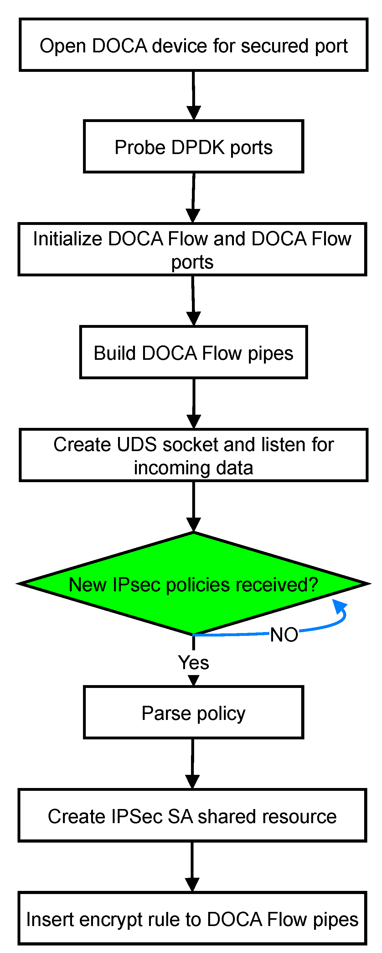
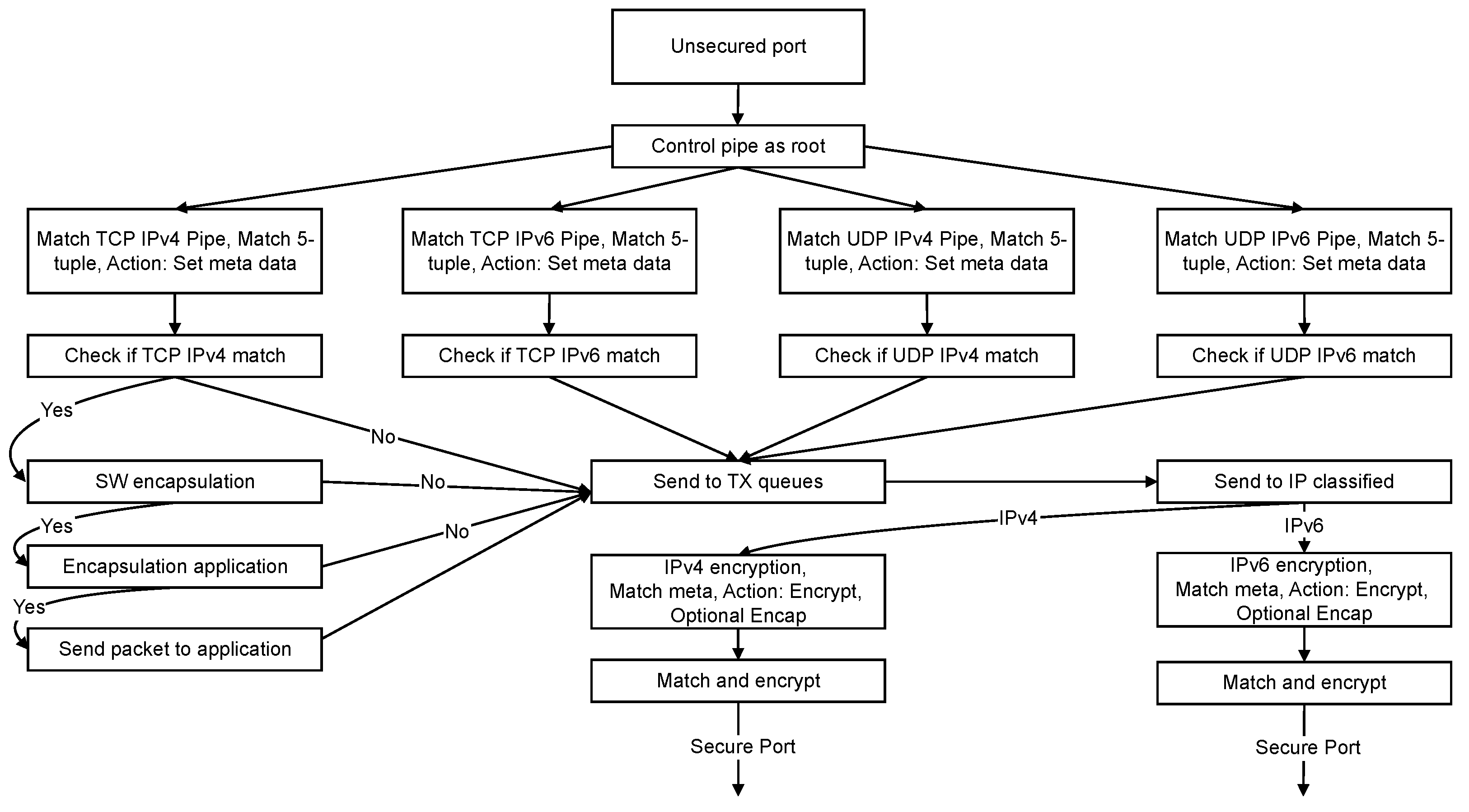
4.2. Algorithmic Procedure

We use the procedure shown in Figure 4 to set up the IPsec tunnel that we present in this work. First, we establish an OpenSSL (https://www.openssl.org/ accessed on 10 January 2024) connection between the two devices. The cipher that we used for the OpenSSL session is TLS_AES_256_GCM_SHA384. The required certificates are self-signed. In a real-life scenario, the self-signed certificates would need to be replaced by certificates issued by a certificate authority. The second step is the exchange of PQC signatures. For this purpose, we use the reference implementation of Falcon [14] and the reference implementation of Dilithium [15]. After that, we exchange a PQC key using Kyber’s reference implementation [16]. The reference implementations of the three PQC algorithms used in this work are available online (https://falcon-sign.info/, https://pq-crystals.org/dilithium/index.shtml, https://pq-crystals.org/kyber/index.shtml accessed on 10 January 2024). The fourth step is the combination of the OpenSSL key with the PQC key by performing an XOR operation with the OpenSSL key and the PQC key. This is called key mixing. The resulting key is secure for as long as at least one of the two mixed keys is not compromised [46]. Ultimately, we use the ephemeral key resulting from mixing the keys to set up the IPsec connection using the pre-shared key method. The IPsec connection is protected by AES-256 GCM encryption which is considered to be secure against quantum attacks [7]. Superuser privileges are required for the execution. The session key remains active for as long as the IPsec SA is active. In case a new key needs to be exchanged, the procedure shown in Figure 4 is repeated.
We execute the procedure shown in Figure 4 on the server machine’s processor directly, on the DPU, and on the Jetson. If the cryptographic operations are executed on the server’s CPU, the DPU is used as simple NIC. The server encrypts the traffic and sends the outgoing traffic already encrypted to the NIC via PCIe 4. While receiving traffic, the NIC forwards the encrypted traffic to the host, and the host machine decrypts the traffic on its own CPU. In this case, the NIC only manages outgoing and incoming connections. It is not used for processing of any kind. If the cryptographic are executed on the NIC, the server sends the outgoing and incoming traffic unencryptedly to the NIC. It thus saves valuable CPU cycles of its own CPU. In this case, the NIC executes all cryptographic operations. It receives the data as plaintext from its host and sends out the data encryptedly. The receiving DPU decrypts the incoming packets and forwards them to the host via PCIe 4.

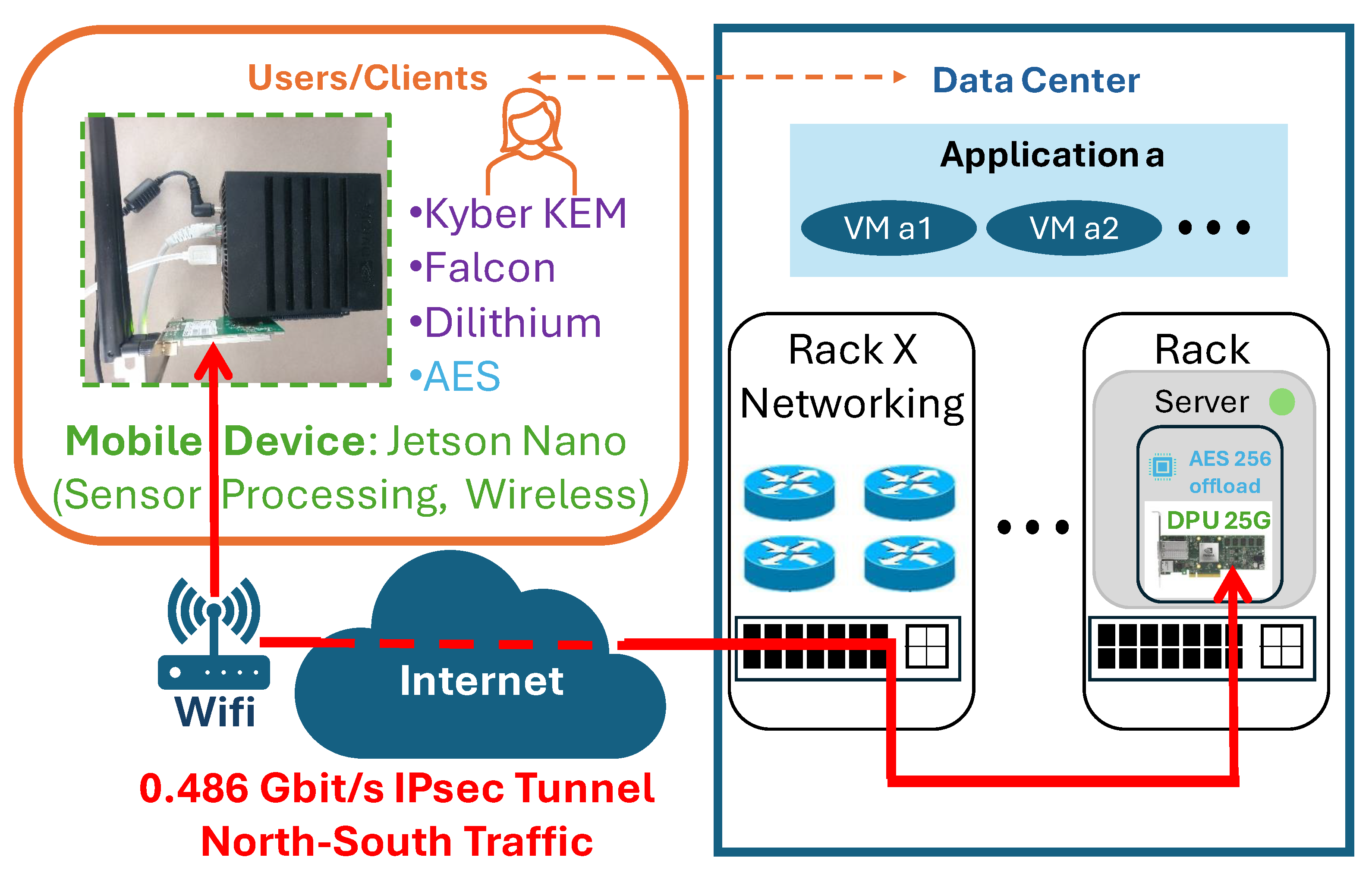
5. Experimental Setup and Methodology

Figure 5 shows the schematical representation of a data center. In a data center, multiple servers are stashed in several racks. All servers are interconnected via a high-speed network within the data center. Different applications are running on the servers. The applications are potentially running a number of virtual machines (VMs) on various different machines that, hence, are required to communicate with each other. In a data center, this is called east–west traffic. External users and clients access the services provided by the applications that are running in the data center via the public internet. This kind of traffic is referred to as north–south traffic.
In this work, we present two scenarios for the application of the PQC-secured IPsec tunnel that we demonstrate in this work. The first scenario emulates an intra-data-center east–west communication at line rate. Our experimental setup for this, shown in Figure 6, represents this scenario: Two Dell PowerEdge 740xd (https://www.dell.com/en-us/shop/dell-poweredge-servers/poweredge-r740xd-rack-server/spd/poweredge-r740xd/pe_r740xd_tm_vi_vp_sb accessed on 10 January 2024) servers are each equipped with an NVIDIA BlueField 2 DPU (https://www.nvidia.com/en-us/networking/products/data-processing-unit/ accessed on 10 January 2024). Each DPU is equipped with eight on-board ARMv8 processors that are clocked with 2750 M Hz . The DPUs are connected via optical fiber with an optical switch. The throughput between DPU and DPU is measured using the VIAVI [47] traffic generator. The VIAVI traffic generator can achieve throughputs of up to 400 Gbit/s. However, the DPUs that we use are capable of 100 Gbit/s, and therefore, we do not make use of VIAVI’s full capabilities. In order to test the throughput, the VIAVI traffic generator is placed in between the two DPUs.
The second scenario that we present in our work is a quantum-safe way for clients to establish a north–south IPsec connection for accessing the services from outside the data center. We demonstrate our north–south IPsec tunnel using a wireless connection. Our setup for this can be seen in Figure 7: a mobile device that seeks to exchange encrypted information with the cloud. As a mobile device, we use an Nvidia Jetson Nano (https://developer.nvidia.com/embedded/jetson-nano accessed on 10 January 2024) that is equipped with a WiFi antenna extension. The Jetson connects to the cloud via a WiFi router. We measure the throughput between the Jetson and a 25 G DPU in the cloud using the iperf (https://iperf.fr/ accessed on 15 January 2024) traffic generator and achieve a 0.486 Gbit/s throughput. We connect the Jetson to a 25 G DPU instead of a 100 G DPU because the WiFi antenna’s maximum throughput is equal to 1 Gbit/s, and therefore, a 25 G DPU is suitable to provide the necessary performance.

6. Results

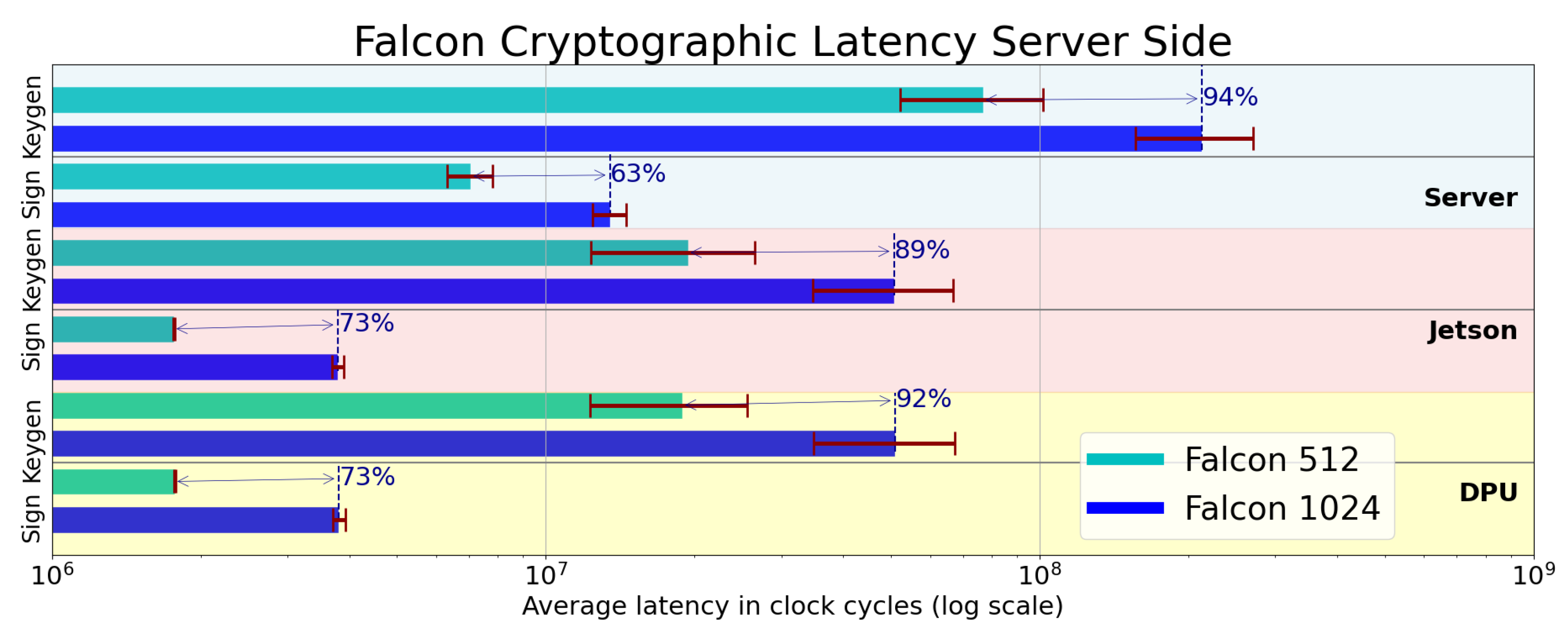
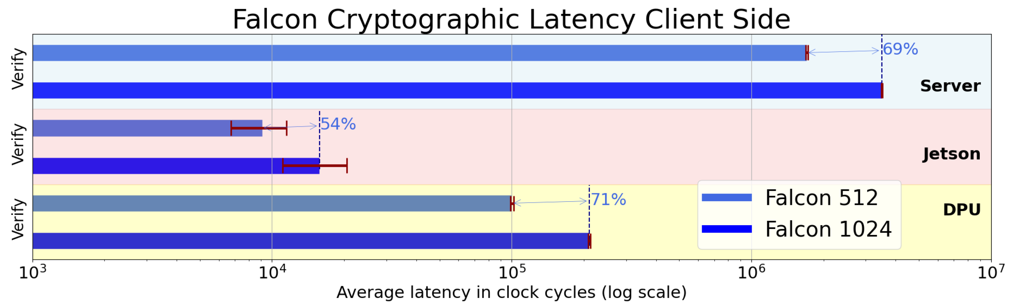
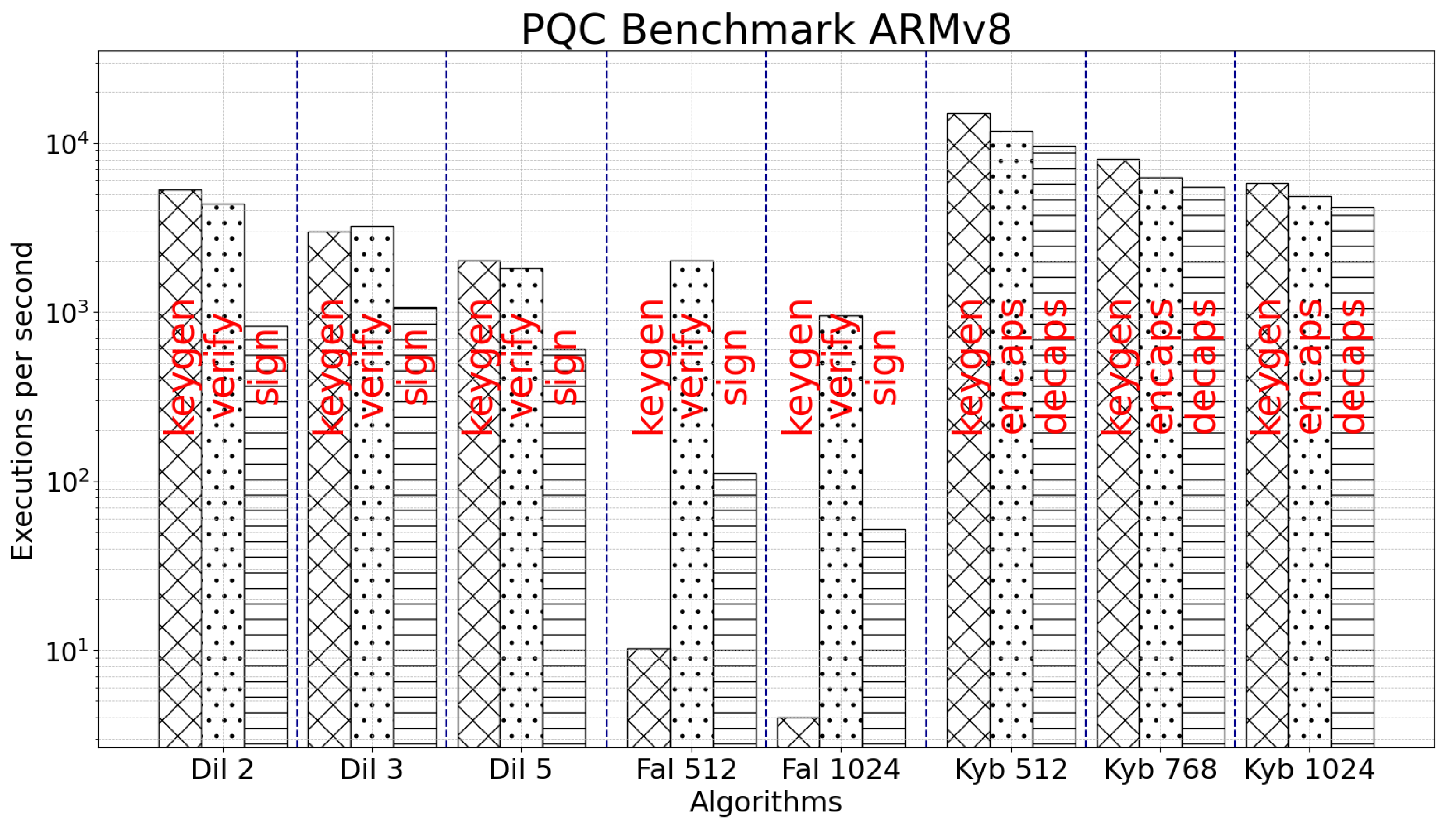
6.1. Signature Algorithms

Figure 4 shows the methodology that we use for setting up the quantum-secure IPsec tunnel that we present in this work. The server machine and the client machine have to perform different tasks. As Dilithium and Falcon are signature algorithms, they are part of step 2 in Figure 4. Hence, the latency introduced by the execution of the algorithms can be attributed to step 2. While executing a signature algorithm, the server machine needs to generate a key and create a signature using the sign process. Figure 8 shows the average required clock cycles while executing Dilithium on the server side on the server directly (blue background), on the Jetson (red background), and on the DPU (yellow background). While signing, a security downgrade from Dilithium 5 down to Dilithium 3 comes with a performance gain between 6% (server) and 39% (DPU) in terms of CPU cycles. Further trading off security for the velocity of execution by using Dilithium 2 instead of 5 yields a performance boost between 41% (server) and 89% (DPU). While generating a key, it is between 35% (server) and 40% (Jetson) faster to use Dilithium 3 instead of Dilithium 5. At the lowest security level, it consumes 89% (server, Jetson, and DPU) less CPU cycles to use Dilithium 2 instead of Dilithium 5.
The cryptographic operations of Dilithium’s client side are shown in Figure 9. The client needs only to verify the signature. The verification process of a Dilithium 5 signature takes between 25% (server) and 43% (Jetson) longer than the verification of a Dilithium 3 signature. Verifying a Dilithium 2 signature is between 65% (server) and 83% quicker than the equivalent process for a Dilithium 5 signature.
The cryptographic latency introduced by Falcon on the server side can be seen in Figure 10. Generating a key for Falcon 1024 takes between 89% (Jetson) and 94% (server) more clock cycles in comparison with Falcon 512. It is of note that the key generation of Falcon is particularly more challenging than Dilithium’s key generation. Falcon’s key generation requires about two orders of magnitude more clock cycles compared to Dilithium’s key generation. Signing requires between 63% (server) and 73% (DPU) more clock cycles for Falcon 1024 while comparing it with Falcon 512.
The cryptographic latency introduced by Falcon on the client side can be seen in Figure 11. The client requires between 54% (Jetson) and 71% (DPU) more clock cycles to verify a Falcon 1024 signature compared to a Falcon 512 signature. Falcon’s and Dilithium’s verification processes are similarly competitive in terms of performance. Dilithium is slightly faster while Falcon is within the same order of magnitude regarding the required CPU clock cycles for the execution.

6.2. Key Exchange Mechanism

Kyber as a key exchange mechanism represents step 3 in Figure 4. The latency added in this step equals the latency caused by the execution of Kyber. The server machine has to perform the key generation and the key decapsulation while the client machine has to execute the key encapsulation. The latency introduced for the server machine can be seen in Figure 12. Upgrading the security level from Kyber 512 to Kyber 768 comes with a penalty in terms of CPU cycles between 33% (DPU) and 40% (server) during the key decapsulation. Furthermore, increasing the security level from Kyber 768 to Kyber 1024 costs between 45% (server) and 57% more CPU (DPU) cycles while performing the key decapsulation. The key generation is generally a more expensive operation compared with key decapsulation. While generating a key for Kyber 512, an additional charge of 32%(server) to 34% (DPU, Jetson) applies. Upgrading the strength from Kyber 768 to Kyber 1024 costs between 28% (server) and 66% more CPU clock cycles while generating a key. The Jetson and the DPU perform very similarly. The server requires more CPU cycles by almost one order of magnitude regarding only the number of clock cycles that are required for the execution of the algorithm. This does not take into account the clock frequency the different processors are operating at.
Figure 13 shows the latency introduced on the client machine. The only operation that the client has to perform is the key encapsulation. Downgrading the security level from Kyber 1024 to Kyber 768 boosts the performance by between 37% (server) and 75% (Jetson). Decreasing the security level to Kyber 512 yields a performance gain of 75% (server) to 113% (DPU) with respect to Kyber 1024.
To examine the performance of the individual steps of the various algorithms, we execute on different processors the main three steps of Falcon and Dilithium (key generation, verify, and sign), as well the main three steps of Kyber (key generation, key encapsulation, and key decapsulation). The results can be seen in Figure 14 for an AMD Ryzen 7 3700X desktop processor, in Figure 15 for the ARMv8 processor on the DPU, and in Figure 16 for the Intel Xeon processor that our servers are equipped with. The metric is executions per second. It is of note here that the Intel Xeon, shown in Figure 16, performs slightly better than the ARMv8, shown in Figure 16, even though the Intel Xeon requires a significant amount of CPU cycles more for the execution of the PQC algorithms. This is due to the higher clock frequency that the Intel Xeon is operating at compared to the ARMv8 processor.
After the keys have been exchanged successfully, during step 4 in Figure 4, we perform an XOR operation between the cryptographic key that we retrieved while setting up an OpenSSL session using classical cryptography and the keys that we have exchanged using Kyber. Ultimately, we perform step 5 in Figure 4 and set up the IPsec tunnel. We do that for both scenarios, east–west traffic and north–south traffic.

6.3. IPsec Tunnel

Using the iperf traffic generator, we analyze the performance of the north–south IPsec tunnel that we set up between the Jetson as a wireless device and the 25 G DPU in the cloud, shown in Figure 7. We achieve an AES-256 GCM encrypted wireless throughput of 0.486 Gbit/s. As this scenario emulates a mobile device communicating via the cloud, the signal travels through a chain of multiple hops. We therefore do not set the maximum transmission unit (MTU) because every device in the chain between the mobile device and the 25G DPU in the cloud can modify the MTU size.
In our intra-data-center east–west traffic scenario, however, we do have control over the MTU size. Thus, after we set up the east–west IPsec tunnel from DPU to DPU, we characterize the tunnel’s throughput with different MTU sizes using the VIAVI traffic generator. The results can be seen in Figure 17. The original plots generated by VIAVI for each MTU can be seen in Figure 18. With small packets, 64 B MTU, we achieve an encrypted throughput of 34 Gbit/s. This can be seen in Figure 18a. Doubling the MTU to 128 B yields an encrypted throughput of 58 Gbit/s, as shown in Figure 18b. Setting the MTU to 256 B in Figure 18c results in an encrypted throughput of 73 Gbit/s. In Figure 18d, at 512 B MTU, we obtain an encrypted throughput of 95 Gbit/s. Ultimately, in Figure 18e,f, starting from 1024 B MTU, we observe an encrypted throughput of 100 Gbit/s line rate. For all MTU sizes that are bigger than, and including 1024 B, the encrypted throughput converges towards 100 Gbit/s. That holds true for jumbo-sized packets due to the fact that the on-board hardware accelerators of the DPU support only operation up to 100 Gbit/s.

7. Discussion

Kyber [16], being the only remaining KEM in the NIST competition chosen for standardization, is integral to every version of the encryption stack presented in this work. The choice of security level for Kyber (NIST levels I, III, or V) can vary based on numerous factors, including security requirements and the processing power of the devices involved. This decision is typically made by the application or, ultimately, by the software developer.
Dilithium [15], developed by the same group (https://pq-crystals.org/ accessed 19 March 2024) that submitted Kyber, offers excellent performance in terms of execution speed when combined with Kyber [16]. However, Dilithium’s signatures are larger compared to Falcon’s, resulting in larger certificates and more data that need to be transmitted over networks. This might not be an issue in high-performance environments, such as data centers, where network bandwidth is abundant, making signature sizes irrelevant. However, in mobile applications with limited and potentially unstable network connections, the larger signature size could negatively impact performance.
Falcon’s performance is inferior to Dilithium’s in terms of computation. Falcon requires more CPU clock cycles per execution, and especially its key generation process is significantly more demanding. Despite this, in scenarios where keys are generated infrequently, the impact of this disadvantage is minimal. However, in high-performance environments with numerous sessions, each requiring its own key, this becomes a significant drawback of Falcon. The advantage Falcon offers is its smaller signature size, which may be more suitable for mobile, low-power, and low-performance environments.

8. Conclusions and Future Work

In this work, we present a software stack to establish a fully offloaded, quantum-safe IPsec tunnel. We first perform a quantum-safe authentication using the PQC signature algorithms Falcon and Dilithium, followed by the key exchange algorithm Kyber. Then, using the quantum-secure key, we set up an IPsec tunnel that is secured by AES-256 GCM. Moreover, we benchmark the performance of the PQC algorithms on multiple CPUs. Dilithium outperforms Falcon in terms of execution speed. However, Falcon’s signature is smaller than Dilithium’s which poses an advantage in environments with low network capacities.
In our experimental setup, we demonstrated an IPsec connection between a mobile device connected to WiFi and a 25 G DPU in the cloud. We did not modify the MTU, considering that every device and hop linking the connection between the Jetson and the DPU could modify the MTU. Using our setup, we achieved an end-to-end encrypted throughput of 0.486 Gbit/s between the Jetson and the 25 G DPU.
Once the IPsec tunnel was established, NVIDIA’s NIC showed excellent performance by offloading cryptographic operations to the NIC’s hardware accelerators, effectively liberating the host machine’s CPU from cryptographic calculations. We confirmed the IPsec tunnel’s performance relative to the MTU size using the VIAVI traffic generator. With small packets of 64 B MTU, we achieved a throughput of 34 Gbit/s. With an MTU of 1024 B, we achieved a full encrypted throughput of 100 Gbit/s line rate, which is the maximum performance attainable with this NIC model. We observed a 100 Gbit/s line rate for all MTU sizes larger than 1024 B, including jumbo packets.
To further accelerate the transition to quantum-resistant algorithms, we identify two major tasks that need to be addressed in the future. First, PQC algorithms must be fully integrated into existing software stacks, transitioning from research environments into production code used in real-life applications. Our work represents a first step towards this direction. Second, the processing power required for PQC algorithms is significantly higher than that of classical algorithms. We therefore anticipate the development of dedicated hardware accelerators specifically for PQC algorithms, similar to the hardware accelerators currently used for classical asymmetric cryptography. This would accelerate the execution speed and reduce the energy consumption while using PQC algorithms.

Author Contributions

Conceptualization, D.C.L., R.A.B. and F.C.; methodology, D.C.L., R.A.B., A.C.A. and F.C.; software, D.C.L., R.A.B. and A.C.A.; validation, D.C.L., R.A.B., A.C.A. and F.C.; writing—original draft preparation, D.C.L. and R.A.B.; writing—review and editing, F.C., J.L.I., I.T.M. and J.J.V.O.; visualization, D.C.L. and R.A.B.; supervision, F.C., J.L.I., I.T.M. and J.J.V.O.; All authors have read and agreed to the published version of the manuscript.

Funding

This work was partly funded by the QUARC project by the European Union Horizon Europe research and innovation program within the framework of Marie Skłodowska-Curie Actions with grant number 101073355 and the CLEVER project by the Key Digital Technologies Joint Undertaking program with grant number 101097560.

Data Availability Statement

The data presented in this study are available in this article.

Conflicts of Interest

J.J.V.O. is employed by NVIDIA. The funders had no role in the design of the study; in the collection, analyses, or interpretation of data; in the writing of the manuscript, or in the decision to publish the results.

Abbreviations

The following abbreviations are used in this manuscript:
AESAdvanced Encryption Standard
AHAuthentication Header
APIApplication Programming Interface
AVX2Advanced Vector Extensions
CACertificate Authority
CPUCentral Processing Unit
CUDACompute Unified Device Architecture
DOCAData Center-on-a-Chip Architecture
DPDKData Plane Development Kit
DPUData Processing Unit
ESPEncapsulation Security Payload
GCMGalois-counter mode
GPUGraphics Processing Unit
IPsecInternet Protocol security
KEMKey Exchange Mechanism
MTUMaximum Transmission Unit
NICNetwork Interface Card
NISTNational Institute of Standards and Technology
NTTNumber Theoretic Transform
PQCPost-Quantum Cryptography
QKDQuantum Key Distribution
SASecurity Association
SISShort Integer Solution
SPISecurity Parameter Index

References

  1. Arute, F.; Arya, K.; Babbush, R.; Bacon, D.; Bardin, J.C.; Barends, R.; Biswas, R.; Boixo, S.; Brandao, F.G.S.L.; Buell, D.A.; et al. Quantum supremacy using a programmable superconducting processor. Nature 2019, 574, 505–510. [Google Scholar] [CrossRef]
  2. Crippa, L.; Tacchino, F.; Chizzini, M.; Aita, A.; Grossi, M.; Chiesa, A.; Santini, P.; Tavernelli, I.; Carretta, S. Simulating Static and Dynamic Properties of Magnetic Molecules with Prototype Quantum Computers. Magnetochemistry 2021, 7, 117. [Google Scholar] [CrossRef]
  3. Codognet, P.; Diaz, D.; Abreu, S. Quantum and Digital Annealing for the Quadratic Assignment Problem. In Proceedings of the 2022 IEEE International Conference on Quantum Software (QSW), Barcelona, Spain, 10–16 July 2022; pp. 1–8. [Google Scholar] [CrossRef]
  4. Hu, F.; Lamata, L.; Wang, C.; Chen, X.; Solano, E.; Sanz, M. Quantum Advantage in Cryptography with a Low-Connectivity Quantum Annealer. Phys. Rev. Appl. 2020, 13, 054062. [Google Scholar] [CrossRef]
  5. Sharma, M.; Choudhary, V.; Bhatia, R.S.; Malik, S.; Raina, A.; Khandelwal, H. Leveraging the power of quantum computing for breaking RSA encryption. Cyber-Phys. Syst. 2021, 7, 73–92. [Google Scholar] [CrossRef]
  6. Dworkin, M.J.; Barker, E.B.; Nechvatal, J.R.; Foti, J.; Bassham, L.E.; Roback, E.; Dray, J.F., Jr. Advanced Encryption Standard (AES). 2001. Available online: https://nvlpubs.nist.gov/nistpubs/fips/nist.fips.197.pdf (accessed on 17 January 2024).
  7. Bonnetain, X.; Naya-Plasencia, M.; Schrottenloher, A. Quantum Security Analysis of AES. IACR Trans. Symmetric Cryptol. 2019, 2019, 55–93. [Google Scholar] [CrossRef]
  8. Alagic, G.; Cooper, D.; Dang, Q.; Dang, T.; Kelsey, J.M.; Lichtinger, J.; Liu, Y.K.; Miller, C.A.; Moody, D.; Peralta, R.; et al. Status Report on the Third Round of the NIST Post-Quantum Cryptography Standardization Process. 2022. Available online: https://nvlpubs.nist.gov/nistpubs/ir/2022/NIST.IR.8413.pdf (accessed on 18 January 2024).
  9. Bernstein, D.J.; Buchmann, J.; Dahmen, E. (Eds.) Introduction to post-quantum cryptography. In Post-Quantum Cryptography; Springer: Berlin/Heidelberg, Germany, 2009; pp. 1–14. [Google Scholar] [CrossRef]
  10. Ding, J.; Schmidt, D. Rainbow, a New Multivariable Polynomial Signature Scheme. In Applied Cryptography and Network Security; Springer: Berlin/Heidelberg, Germany, 2005; pp. 164–175. [Google Scholar]
  11. Bernstein, D.J.; Hülsing, A.; Kölbl, S.; Niederhagen, R.; Rijneveld, J.; Schwabe, P. The SPHINCS+ Signature Framework. Cryptology ePrint Archive, Paper 2019/1086. 2019. Available online: https://eprint.iacr.org/2019/1086 (accessed on 20 December 2023).
  12. Overbeck, R.; Sendrier, N. Code-based cryptography. In Post-Quantum Cryptography; Bernstein, D.J., Buchmann, J., Dahmen, E., Eds.; Springer: Berlin/Heidelberg, Germany, 2009; pp. 95–145. [Google Scholar] [CrossRef]
  13. Albrecht, M.R.; Bernstein, D.J.; Chou, T.; Cid, C.; Gilcher, J.; Lange, T.; Maram, V.; Von Maurich, I.; Misoczki, R.; Niederhagen, R.; et al. Classic McEliece: Conservative Code-Based Cryptography. 2022. Available online: https://inria.hal.science/hal-04288769/document (accessed on 13 January 2024).
  14. Fouque, P.-A.; Hoffstein, J.; Kirchner, P.; Lyubashevsky, V.; Pornin, T.; Prest, T.; Ricosset, T.; Seiler, G.; Whyte, W.; Zhang, Z. Fast-Fourier Lattice-Based Compact Signatures over NTRU. 2019. Available online: https://falcon-sign.info/ (accessed on 15 January 2024).
  15. Ducas, L.; Kiltz, E.; Lepoint, T.; Lyubashevsky, V.; Schwabe, P.; Seiler, G.; Stehlé, D. CRYSTALS-Dilithium: A Lattice-Based Digital Signature Scheme. IACR Trans. Cryptogr. Hardw. Embed. Syst. 2018, 2018, 238–268. [Google Scholar] [CrossRef]
  16. Bos, J.; Ducas, L.; Kiltz, E.; Lepoint, T.; Lyubashevsky, V.; Schanck, J.M.; Schwabe, P.; Seiler, G.; Stehle, D. CRYSTALS—Kyber: A CCA-Secure Module-Lattice-Based KEM. In Proceedings of the 2018 IEEE European Symposium on Security and Privacy (EuroS&P), London, UK, 24–26 April 2018; pp. 353–367. [Google Scholar] [CrossRef]
  17. Fitzgibbon, G.; Ottaviani, C. Constrained Device Performance Benchmarking with the Implementation of Post-Quantum Cryptography. Cryptography 2024, 8, 21. [Google Scholar] [CrossRef]
  18. Vidaković, M.; Miličević, K. Performance and Applicability of Post-Quantum Digital Signature Algorithms in Resource-Constrained Environments. Algorithms 2023, 16, 518. [Google Scholar] [CrossRef]
  19. Rubio García, C.; Rommel, S.; Takarabt, S.; Vegas Olmos, J.J.; Guilley, S.; Nguyen, P.; Tafur Monroy, I. Quantum-resistant Transport Layer Security. Comput. Commun. 2024, 213, 345–358. [Google Scholar] [CrossRef]
  20. Paul, S.; Kuzovkova, Y.; Lahr, N.; Niederhagen, R. Mixed Certificate Chains for the Transition to Post-Quantum Authentication in TLS 1.3. In Proceedings of the ASIA CCS ’22: 2022 ACM on Asia Conference on Computer and Communications Security, New York, NY, USA, 30 May–3 June 2022; pp. 727–740. [Google Scholar] [CrossRef]
  21. Karabulut, E.; Aysu, A. A Hardware-Software Co-Design for the Discrete Gaussian Sampling of FALCON Digital Signature. IACR Cryptol. ePrint Arch. 2023, 2023, 908. [Google Scholar]
  22. Howe, J.; Oder, T.; Krausz, M.; Güneysu, T. Standard Lattice-Based Key Encapsulation on Embedded Devices. IACR Trans. Cryptogr. Hardw. Embed. Syst. 2018, 2018, 372–393. [Google Scholar]
  23. Gupta, N.; Jati, A.; Chauhan, A.K.; Chattopadhyay, A. PQC Acceleration Using GPUs: FrodoKEM, NewHope, and Kyber. IEEE Trans. Parallel Distrib. Syst. 2021, 32, 575–586. [Google Scholar]
  24. Gupta, N.; Jati, A.; Chattopadhyay, A.; Jha, G. Lightweight Hardware Accelerator for Post-Quantum Digital Signature CRYSTALS-Dilithium. Cryptology ePrint Archive, Paper 2022/496. 2022. Available online: https://eprint.iacr.org/2022/496 (accessed on 16 January 2024).
  25. Karl, P.; Schupp, J.; Fritzmann, T.; Sigl, G. Post-Quantum Signatures on RISC-V with Hardware Acceleration. Cryptology ePrint Archive, Paper 2022/538. 2022. Available online: https://eprint.iacr.org/2022/538 (accessed on 20 January 2024).
  26. Yaman, F.; Mert, A.C.; Öztürk, E.; Savaş, E. A Hardware Accelerator for Polynomial Multiplication Operation of CRYSTALS-KYBER PQC Scheme. In Proceedings of the 2021 Design, Automation & Test in Europe Conference & Exhibition (DATE), Grenoble, France, 1–5 February 2021; pp. 1020–1025. [Google Scholar]
  27. Mert, A.C.; Öztürk, E.; Savaş, E. Design and Implementation of a Fast and Scalable NTT-Based Polynomial Multiplier Architecture. In Proceedings of the 2019 22nd Euromicro Conference on Digital System Design (DSD), Kallithea, Greece, 28–30 August 2019; pp. 253–260. [Google Scholar] [CrossRef]
  28. Şah Özcan, A.; Savaş, E. Two Algorithms for Fast GPU Implementation of NTT. Cryptology ePrint Archive, Paper 2023/1410. 2023. Available online: https://eprint.iacr.org/2023/1410 (accessed on 20 January 2024).
  29. Schmid, M.; Amiet, D.; Wendler, J.; Zbinden, P.; Wei, T. Falcon Takes Off—A Hardware Implementation of the Falcon Signature Scheme. Cryptology ePrint Archive, Paper 2023/1885. 2023. Available online: https://eprint.iacr.org/2023/1885 (accessed on 20 January 2024).
  30. Ullah, S.; Choi, J.; Oh, H. IPsec for high speed network links: Performance analysis and enhancements. Future Gener. Comput. Syst. 2020, 107, 112–125. [Google Scholar] [CrossRef]
  31. Aguilera, A.C.; Clemente, X.A.I.; Lawo, D.; Monroy, I.T.; Olmos, J.V. First end-to-end PQC protected DPU-to-DPU communications. Electron. Lett. 2023, 59, e12901. [Google Scholar] [CrossRef]
  32. Lawo, D.C.; Frantz, R.; Aguilera, A.C.; Clemente, X.A.I.; Podleś, M.P.; Imaña, J.L.; Monroy, I.T.; Olmos, J.J.V. Falcon/Kyber and Dilithium/Kyber Network Stack on Nvidia’s Data Processing Unit Platform. IEEE Access 2024, 12, 38048–38056. [Google Scholar] [CrossRef]
  33. Aguilera, A.C.; Abu Bakar, R.; Alhamed, F.; Garcia, C.R.; Imaña, J.; Monroy, I.T.; Cugini, F.; Olmos, J.V. First Line-rate End-to-End Post-Quantum Encrypted Optical Fiber Link Using Data Processing Units (DPUs). In Proceedings of the 2024 Optical Fiber Communications Conference and Exhibition (OFC), San Diego, CA, USA, 26–28 March 2024; pp. 1–3. [Google Scholar]
  34. Alia, O.; Huang, A.; Luo, H.; Amer, O.; Pistoia, M.; Lim, C. Quantum-safe 10 Gbps Site-to-Site IPsec VPN Tunnel over 46 km Deployed Fibre. In Proceedings of the Optical Fiber Communication Conference (OFC) 2024, San Diego, CA, USA, 24–28 March 2024; Optica Publishing Group: Washington, DC, USA, 2024; p. Th3B.5. [Google Scholar] [CrossRef]
  35. Rencis, E.; Vīksna, J.; Kozlovičs, S.; Celms, E.; Lāriņš, D.J.; Petručeņa, K. Hybrid QKD-based framework for secure enterprise communication system. Procedia Comput. Sci. 2024, 239, 420–428. [Google Scholar] [CrossRef]
  36. Bae, S.; Chang, Y.; Park, H.; Kim, M.; Shin, Y. A Performance Evaluation of IPsec with Post-Quantum Cryptography. In Information Security and Cryptology—ICISC 2022; Seo, S.H., Seo, H., Eds.; Springer: Cham, Switzerland, 2023; pp. 249–266. [Google Scholar]
  37. Kumar, S.; Dalal, S.; Dixit, V. The osi model: Overview on the seven layers of computer networks. Int. J. Comput. Sci. Inf. Technol. Res. 2014, 2, 461–466. [Google Scholar]
  38. Hamed, H.; Al-Shaer, E.; Marrero, W. Modeling and verification of IPSec and VPN security policies. In Proceedings of the 13TH IEEE International Conference on Network Protocols (ICNP’05), Boston, MA, USA, 6–9 November 2005; pp. 10–278. [Google Scholar] [CrossRef]
  39. Dhall, H.; Dhall, D.; Batra, S.; Rani, P. Implementation of IPSec Protocol. In Proceedings of the 2012 Second International Conference on Advanced Computing & Communication Technologies, Rohtak, India, 7–8 January 2012; pp. 176–181. [Google Scholar] [CrossRef]
  40. Sadikin, M.A.; Wardhani, R.W. Implementation of RSA 2048-bit and AES 256-bit with digital signature for secure electronic health record application. In Proceedings of the 2016 International Seminar on Intelligent Technology and Its Applications (ISITIA), Lombok, Indonesia, 28–30 July 2016; pp. 387–392. [Google Scholar] [CrossRef]
  41. Maurer, U.M.; Wolf, S. The Diffie–Hellman Protocol. Des. Codes Cryptogr. 2000, 19, 147–171. [Google Scholar] [CrossRef]
  42. Gentry, C.; Peikert, C.; Vaikuntanathan, V. Trapdoors for Hard Lattices and New Cryptographic Constructions. Cryptology ePrint Archive, Paper 2007/432. 2007. Available online: https://eprint.iacr.org/2007/432 (accessed on 20 January 2024).
  43. Soni, D.; Basu, K.; Nabeel, M.; Aaraj, N.; Manzano, M.; Karri, R. Hardware Architectures for Post-Quantum Digital Signature Schemes. In Hardware Architectures for Post-Quantum Digital Signature Schemes; Springer International Publishing: Cham, Switzerland, 2021. [Google Scholar] [CrossRef]
  44. Aragon, N.; Barreto, P.; Bettaieb, S.; Bidoux, L.; Blazy, O.; Deneuville, J.C.; Gaborit, P.; Ghosh, S.; Gueron, S.; Güneysu, T.; et al. BIKE: Bit Flipping Key Encapsulation. 2022. Available online: https://bikesuite.org/ (accessed on 15 January 2024).
  45. Jao, D.; Azarderakhsh, R.; Campagna, M.; Costello, C.; De Feo, L.; Hess, B.; Jalili, A.; Koziel, B.; LaMacchia, B.; Longa, P.; et al. SIKE: Supersingular Isogeny Key Encapsulation. 2017. Available online: https://static1.squarespace.com/static/5fdbb09f31d71c1227082339/t/5ff378bdac5ecf06b683b05b/1609791681245/2017-ECCinvitedtalk.pdf (accessed on 15 January 2024).
  46. Meher, K.; MidhunChakkaravarthy, D. New Approach to Combine Secret Keys for Post-Quantum (PQ) Transition. Indian J. Comput. Sci. Eng. 2021, 12, 629–633. [Google Scholar]
  47. Suzuki, T.; Kim, S.Y.; Kani, J.i.; Yoshida, T. Low-latency PON PHY implementation on GPUs for fully software-defined access networks. IEEE Netw. 2022, 36, 108–114. [Google Scholar]
Figure 1. Chain of trust: The root CA signs the intermediate certificate. The end-entity certificate’s authenticity is confirmed by one or more intermediate CAs. Hence, trust is established.
Futureinternet 16 00300 g001
Figure 2. Overview of DOCA IPsec workflow. The sequential steps involved in setting up IPSec policies and processing network traffic within the BlueField environment are illustrated.
Futureinternet 16 00300 g002
Figure 3. DOCA IPsec Flow diagram.
Futureinternet 16 00300 g003
Figure 4. Methodology: First, using self-signed certificates, an OpenSSL session is established. The used cipher was TLS_AES_256_GCM_SHA384. Then, PQC signatures are exchanged. As a third step, Kyber is used to exchange a key. Fourthly, the key retrieved by Kyber and the key established by the OpenSSL session are mixed. Ultimately, an IPsec tunnel is set up using the mixed ephemeral key.
Futureinternet 16 00300 g004
Figure 5. Schematic representation of a data center: Multiple racks host many servers, all interconnected via the local intra-data-center network. Different applications are hosted. Traffic within the data center is referred to as east–west traffic. Incoming/outgoing traffic is called north–south traffic. External users and clients access the services.
Futureinternet 16 00300 g005
Figure 6. Two identical servers are each equipped with an Nvidia BlueField 2 100 G DPU. The DPUs are connected via optical fiber to an optical switch and IPsec connection established with following packet header fields. This emulates the east–west traffic in the intra-data-center scenario.
Futureinternet 16 00300 g006
Figure 7. Wireless setup: An Nvidia Jetson Nano connects to a WiFi using a WiFi antenna extension. The Jetson establishes a PQC-secured IPsec tunnel and connects through the network to a server that is equipped with a 25G DPU.
Futureinternet 16 00300 g007
Figure 8. Cryptographic latency introduced by the execution of Dilithium’s keygen and Dilithium’s sign executed on the server side. The server device was a Dell PowerEdge server, equipped with an Intel Xeon CPU, an NVIDIA Jetson (the wireless device in our setup), and an NVIDIA BlueField 2 DPU.
Futureinternet 16 00300 g008
Figure 9. Cryptographic latency introduced by the execution of Dilithium’s verification executed on the client side. The server device was a Dell PowerEdge server, equipped with an Intel Xeon CPU, an NVIDIA Jetson (the wireless device in our setup), and an NVIDIA BlueField 2 DPU.
Futureinternet 16 00300 g009
Figure 10. Cryptographic latency introduced by the execution of Falcon’s key generation and Falcon’s sign executed on the server side. The server device was a Dell PowerEdge server, equipped with an Intel Xeon CPU, an NVIDIA Jetson (the wireless device in our setup), and an NVIDIA BlueField 2 DPU.
Futureinternet 16 00300 g010
Figure 11. Cryptographic latency introduced by the execution of Falcon’s verification executed on the client side. The server device was a Dell PowerEdge server, equipped with an Intel Xeon CPU, an NVIDIA Jetson (the wireless device in our setup), and an NVIDIA BlueField 2 DPU.
Futureinternet 16 00300 g011
Figure 12. Cryptographic latency introduced by the execution of Kyber’s key generation and Kyber’s key decapsulation executed on the server side. The server device was a Dell PowerEdge server, equipped with an Intel Xeon CPU, an NVIDIA Jetson (the wireless device in our setup), and an NVIDIA BlueField 2 DPU.
Futureinternet 16 00300 g012
Figure 13. Cryptographic latency introduced by the execution of Kyber’s key encapsulation executed on the client side. The server device was a Dell PowerEdge server, equipped with an Intel Xeon CPU, an NVIDIA Jetson (the wireless device in our setup), and an NVIDIA BlueField 2 DPU.
Futureinternet 16 00300 g013
Figure 14. Falcon’s and Dilithium’s main steps (key generation, verification, and sign) and Kyber’s main steps (key generation, key encapsulation, and key decapsulation) executed on an AMD Ryzen 7 processor.
Futureinternet 16 00300 g014
Figure 15. Falcon’s and Dilithium’s main steps (key generation, verification, and sign) and Kyber’s main steps (key generation, key encapsulation, and key decapsulation) executed on an ARMv8 processor.
Futureinternet 16 00300 g015
Figure 16. Falcon’s and Dilithium’s main steps (key generation, verification, and sign) and Kyber’s main steps (key generation, key encapsulation, and key decapsulation) executed on an Intel Xeon processor.
Futureinternet 16 00300 g016
Figure 17. AES-256 GCM encrypted IPsec throughput between DPU and DPU depending on the set MTU. We achieve 100 Gbit/s from 1024 B MTU on.
Futureinternet 16 00300 g017
Figure 18. Throughput of the IPsec tunnel with different MTU sizes. The traffic is generated by VIAVI and passed through the IPsec tunnel that we present in this work. For all MTU sizes equal to or bigger than 1024 B, we achieve the maximum supported line rate of 100 Gbit/s. (a) 64 B MTU; (b) 128 B MTU; (c) 256 B MTU; (d) 512 B MTU; (e) 1024 B MTU; (f) 1518 B MTU.
Futureinternet 16 00300 g018
Table 1. Signature (Sig) and public key (Pub key) sizes of Falcon and Dilithium in bytes for different NIST security levels (I, II, III, and V). Public key (Pub key) and encapsulation (Encaps) size of Kyber in bytes. For SPHINCS+, the sizes in bytes are indicated for the use of SHA-256 128-bit (NIST I), SHA-256 192-bit (NIST III), and SHA-256 256-bit hashing (NIST V).
Algorithm IIIIIIV
KyberPub key800 11841568
KyberEncaps768 10881568
DilithiumPub key 131219522592
DilithiumSig 242032934595
FalconPub key897 1793
FalconSig666 1280
SPHINCS+Pub key32 4864
SPHINCS+Sig17,088 35,66449,856
Table 2. Public key (Pub key) and signature (Sig) sizes of classical signature algorithms in bytes [19]. Classical signature and public key sizes are considerably smaller compared to the sizes employed in PQC signature algorithms.
AlgorithmPub KeySig
RSA 1024128128
RSA 2048256256
RSA 4096512512
SECP384r14896
SECP521r165132
Disclaimer/Publisher’s Note: The statements, opinions and data contained in all publications are solely those of the individual author(s) and contributor(s) and not of MDPI and/or the editor(s). MDPI and/or the editor(s) disclaim responsibility for any injury to people or property resulting from any ideas, methods, instructions or products referred to in the content.

