Abstract
Fuel cell hybrid electric vehicles have the advantages of zero emission, high efficiency and fast refuelling, etc. and are one of the key directions for vehicle development. The energy management problem of fuel cell hybrid electric vehicles is the key technology for power distribution. The traditional power following strategy has the advantage of a real-time operation, but the power correction is usually based only on the state of charge of a lithium battery, which causes the operating point of the fuel cell to be in the region of a low efficiency. To solve this problem, this paper proposes a hybrid power-following-fuzzy control strategy, where a fuzzy logic control strategy is used to optimise the correction module based on the power following strategy, which regulates the state of charge while correcting the output power of the fuel cell towards the efficient operating point. The results of the joint simulation with Matlab + Advisor under the Globally Harmonised Light Vehicle Test Cycle Conditions show that the proposed strategy still ensures the advantages of real-time energy management, and for the hydrogen fuel cell, the hydrogen consumption is reduced by 13.5% and 4.1% compared with the power following strategy and the fuzzy logic control strategy, and the average output power variability is reduced by 14.6% and 5.1%, respectively, which is important for improving the economy of the whole vehicle and prolonging the lifetime of fuel cell.
1. Introduction
With the number of car ownership increasing, the global environmental problem due to car emissions is becoming increasingly more prominent [1,2]. Now, the development of new energy vehicles has been the focus of automotive research direction. New energy vehicles can be divided into pure electric vehicles, fuel cell hybrid electric vehicles (FCHEVs), hybrid vehicles and so on, according to the use of different power sources [3]. FCHEVs are considered to be new energy vehicles with great potential due to their advantages of “high efficiency, cleanliness and zero pollution” [4,5]. Considering the shortcomings of soft output characteristics, poor power performance and low energy utilisation of single-source fuel cell vehicles [6], a multi-source power approach is usually adopted. In this paper, a hybrid power system, fuel cell + lithium battery (FCHPS), is selected as the object of study, where the proton exchange membrane fuel cell (PEMFC) is the main power source, and the lithium battery is used as the auxiliary power source. The PEMFC is connected to the bus through a unidirectional DC-DC converter, while the lithium battery is directly connected to the bus [7]. In fuel cell vehicles, the core of the technology is to implement a reasonable power distribution to ensure the safe operation of the fuel cell and auxiliary power sources [8], to make the fuel cell work more efficiently and to avoid frequent fluctuations of the fuel cell power as much as possible, so as to improve the economy and reliability of the whole vehicle. There are currently two main energy management strategies (EMSs): rule-based and optimisation-based. Rule-based strategies can be further divided into deterministic rules and fuzzy rules, and optimisation-based energy management strategies can be divided into global optimisation and instantaneous optimisation energy management strategies [8].
Dynamic programming (DP) is a widely used algorithm in global optimal control strategies [9,10,11]. The DP algorithm requires acquiring all the operating condition information in advance and deriving the control law through backward reasoning. Due to its computationally intensive nature, it is not suitable for real-time applications, but it can generally be used as a benchmark algorithm for other energy management strategies [12]. The instantaneous optimisation strategy solves the optimisation problem using an instantaneous minimisation of the hydrogen consumption cost function, which is updated in real time. The equivalent consumption minimisation strategy (ECMS) [13] and Pontryagin’s minimum principle (PMP) [14,15] can approximate the global optimal solution by appropriately simplifying the whole vehicle model and selecting the appropriate equivalence coefficients. However, this method requires the precise selection of equivalence coefficients and construction of the corresponding prediction model, which are computationally complex and not easy for real-time applications.
The rule-based energy management strategy is not as good as the optimisation-based strategy in terms of optimising the control effect, but because it does not need to anticipate all the information about the driving conditions, and the formulation of the rules is mainly based on the professional knowledge and experience of the engineers and technicians, the real-time performance of the rule-based strategy will be a bit better. Based on the IF-THEN rules and the membership functions [15], we can design the FLCS. In the design process of fuzzy logic, fuzzification, fuzzy inference and defuzzification are required. Among them, fuzzy reasoning is based on the IF-THEN rule. Literatures [16,17] propose an energy management strategy based on FLCS, which aims to reduce hydrogen consumption by considering its dynamic constraints as well as the state of charge of the batteries, while improving the durability of the power source, making the energy flow perfectly distributed among the sources under the UDDS cycle condition, and taking the response time of each power source into account to prolong its lifetime. Zhou [18] proposed a composite fuzzy logic control strategy (FLCS) by designing the main fuzzy controller and sub-fuzzy controller, respectively. The results showed that the hydrogen consumption of this strategy is reduced by 0.66 g compared to the PFS, and the state of charge (SOC) of the battery is maintained in the desired range, which further improves the economy of the whole vehicle and extends the life of the battery. However, without much engineering experience as theoretical support, the fuzzy controller will deviate from optimality if the fuzzy rules are not well designed. To address the above problems, researchers have proposed to solve the problem of unreasonable fuzzy rule design by optimising the parameters of the fuzzy controller using an intelligent optimisation algorithm. Zhang R [19] proposed a new fuzzy predictive controller for hybrids, including a low-pass filter and an improved genetic algorithm. The results showed that the strategy can effectively reduce the fluctuation of fuel cell output power and extend the service life of the hybrid system. However, hydrogen consumption increased by 10%. Qiang Li [20] proposed a global optimisation of fuzzy controller parameters using a multi-objective genetic algorithm NSGA-II to obtain the Pareto optimal solution set through multi-objective optimisation, completing the optimisation of the membership function and the fuzzy control rules in order to improve the economy and durability of the fuel cell. The simulation results showed that after the optimisation process, the performance of the fuel cell was significantly improved, and it was able to operate in the efficient power range for a longer period of time. In addition, the number of detrimental variable loads was significantly reduced from 54 to 8. Overall, the approach significantly improves vehicle economy and fuel cell durability. Common energy management strategies are deterministic rule-based approaches, which include state machine control strategy, thermostat control strategy and power following strategy (PFS). These rule-based design methods are widely recognized as the most practical energy management methods due to their simplicity and practicality. State machine-based energy management strategies require information about the previous state of the system as well as the current inputs, and they execute the outputs based on a defined flow chart or decision tree [21,22]. The core of the state machine control strategy is to ensure that the fuel cell has different output powers in different states [23]. The literature [24] proposed an improved state machine energy management strategy, which is simulated and verified under two cycle conditions, New European Driving Cycle (NEDC) and Urban Dynamometer Driving Schedule (UDDS), and the results showed that the improved strategy can achieve an optimal effect close to that of DP. In addition, the thermostat energy management control strategy maintains the SOC to fluctuate within a certain range by controlling the start and stop of the fuel cell, while ensuring that the fuel cell outputs power at a high-efficiency operating point. However, this control strategy results in frequent starts/stops of the fuel cell, which significantly reduces its lifetime. The PFS is an improved thermostat strategy that generally controls the output of the fuel cell according to the SOC of the battery and the power demanded by the whole vehicle, maintaining the SOC while reducing the frequent fluctuations of the fuel cell, which is conducive to improving the lifetime of PEMFC [25]. Comparison of various EMSs is shown as Table 1.

Table 1.
Comparison of various EMSs.
The PFS is one of the most widely used control strategies in automobiles due to its simple design, easy implementation, and high real-time performance. This strategy also has some defects: when directly applying PFS to fuel cell vehicles, there will be a situation when the fuel cell output operating point is in the low-efficiency region after SOC correction, which will not be conducive to the improvement of vehicle economy.
In this study, we adopt FLCS to take the lithium battery SOC and fuel cell demand output power before SOC regulation as input variables, and the power correction coefficient as the output variable, to realize real-time adjustment of the correction coefficients, to maintain the SOC fluctuating within a certain range, and, at the same time, as far as possible, to move the fuel cell output power to the high-efficiency operating point correction [25] so as to improve the economy and durability of the whole vehicle [26].
The remainder of the paper is structured as follows. In Section 2, the configuration of a FCHPS and the components are modelled. The PFS-FLCS is proposed, and the control rules are introduced in Section 3. In Section 4, simulation validation is carried out. The performance of the proposed strategy is compared with the PFS and the FLCS. Section 5 draws the main conclusions of the paper.
Notes on abbreviations: Fuel Cell Hybrid Electric Vehicle (FCHEV), Fuel Cell Hybrid Power System (FCHPS), Energy Management Strategy (EMS), Fuel Cell + Lithium Battery (FC+B), Proton Exchange Membrane Fuel Cell (PEMFC), State of Charge (SOC), Power Following Strategy (PFS), Fuzzy Logic Control Strategy (FLCS), Hybrid Power-Following-Fuzzy Control Strategy (PFS-FLCS), Dynamic Programming (DP), Equivalent Consumption Minimisation Strategy (ECMS), Pontryagin’s Minimum Principle (PMP), Globally Harmonised Light Vehicle Test Cycle Conditions (WLTC), New European Driving Cycle (NEDC) and Urban Dynamometer Driving Schedule (UDDS).
2. Fuel Cell Hybrid System Architecture and Modelling
2.1. Fuel Cell Hybrid System Architecture
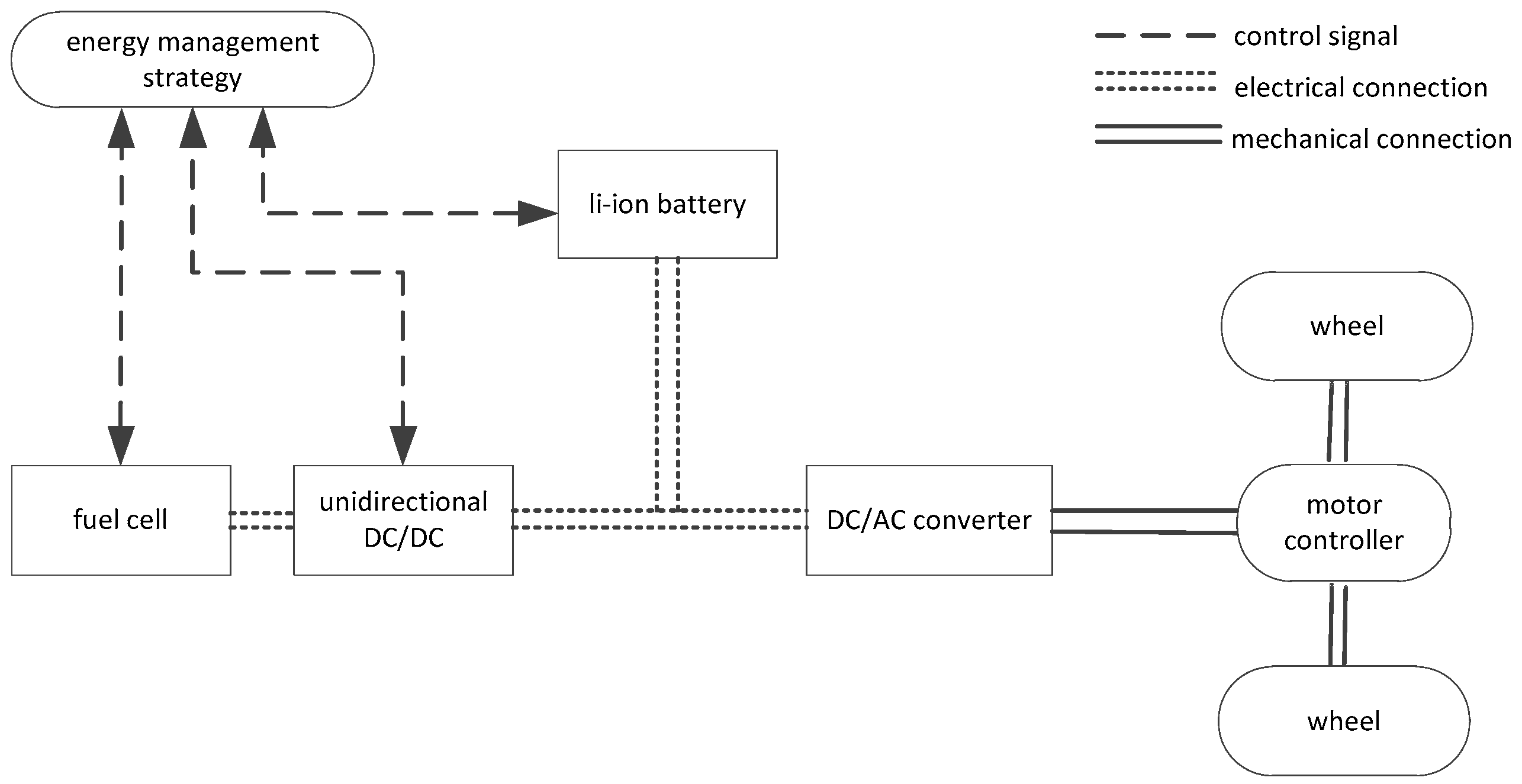
According to the power performance index shown in Table 2 to be achieved by the FCHEV, the parameters of its powertrain components are matched [27]. The powertrain structure and technical parameters of the whole vehicle are shown in Figure 1 and Table 3.
Table 2.
The power performance indexes of FCHEV.
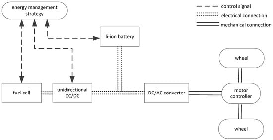
Figure 1.
System structure of FCHEV.
Table 3.
Vehicle technical parameters.
2.2. Fuel Cell Model
A fuel cell power source is a fuel cell stack consisting of several single fuel cells, and the net output voltage can be expressed by the following equation:
where is the fuel cell net output voltage, is the open circuit voltage, is the activation loss voltage, is the ohmic loss voltage, is the concentration difference polarisation voltage, is the output current, and is the internal resistance.
The fuel cell system requires ancillary equipment to support its operation during initial start-up, and the energy demand of this equipment is supplied by the fuel cell itself, so the net output power of the fuel cell system can be given by the following equation:
where is the net output power of the fuel cell, is the total output power, and is the power consumed by auxiliaries.
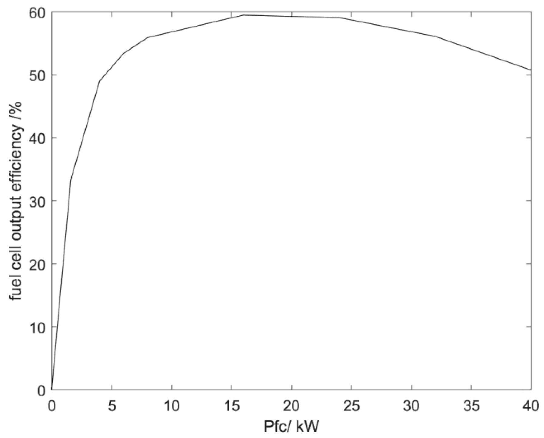
As can be seen in Figure 2, the fuel cell operates at its highest efficiency, close to 60%, when its output is about 23 kW. In the 5–40 kW range, the operating efficiency remains above 50 percent. However, if the output power of the fuel cell is too low or too high, the output efficiency of PEMFC will decrease, leading to an increase in hydrogen consumption, which is not conducive to improving the overall vehicle economy and may damage the performance of the fuel cell. To reduce the hydrogen consumption of the fuel cell and improve fuel economy, the power output of the fuel cell should be kept within the efficient operating range as far as possible.

Figure 2.
PEMFC work efficiency chart.
2.3. Lithium Battery Model
A storage battery is a device that can directly convert chemical energy into electric energy, which is safe, reliable and has stable output voltage. At present, the storage batteries widely used by all kinds of electric vehicles mainly include lead-acid batteries (VRLA), nickel-cadmium batteries (Ni-Cd), nickel-metal hydride batteries (Ni-MH), lithium-ion batteries (Li-Ion), etc. The lithium-ion battery is the most well-known type of storage battery at present, and it is also the modern high-performance battery [28,29]. The lithium-ion battery is currently the most well-known class of batteries but also a representative of modern high-performance batteries. At present, the majority of lithium-ion batteries use lithium phosphate as the battery cathode material.
At present, the equivalent circuit model is usually used to model the lithium battery, and we adopt the internal resistance model as the equivalent circuit model. Although the model cannot reflect the dynamic characteristics of the battery accurately, it can reflect the energy consumption realistically, quickly and in a way that is easily understandable. Its circuit principle is shown in Figure 3:
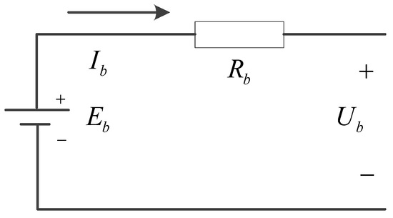
Figure 3.
Battery equivalent circuit.
In the diagram above, —supply voltage; —terminal voltage; —electric current; —equivalent internal resistance of the battery.
The output power of a lithium battery can be expressed as:
The battery circuit current can be expressed as:
The state of charge of a lithium battery at the current moment can be expressed by the following equation:
In the above equation, —initial state of charge of battery; —state of charge of battery; —maximum state of charge of battery; —initial moment.
The battery module consists of five main modules: open-circuit voltage and internal resistance calculation module, power limitation module, current calculation module, SOC estimation module, and battery thermal modelling module. An accurate estimation of SOC is a very challenging task; hence, we calculate the actual SOC value of the battery of this module based on the battery current, and its value is estimated through continuous iteration and gradually approaching the real value.
2.4. Drive Motor Model
The drive motor is the only component in a fuel cell vehicle that directly provides propulsive power to the vehicle. During driving, the drive motor acts as an electric motor, converting the electrical energy provided by the fuel cell system and the battery system into the mechanical energy required by the vehicle to propel it forward. At the same time, during braking, the drive motor recovers braking energy and determines whether the battery needs to be recharged according to its state of charge. The relationship between motor torque, speed and power is given by Equation (8):
where is the motor power; is the motor torque; is the motor efficiency; is the motor angular velocity.
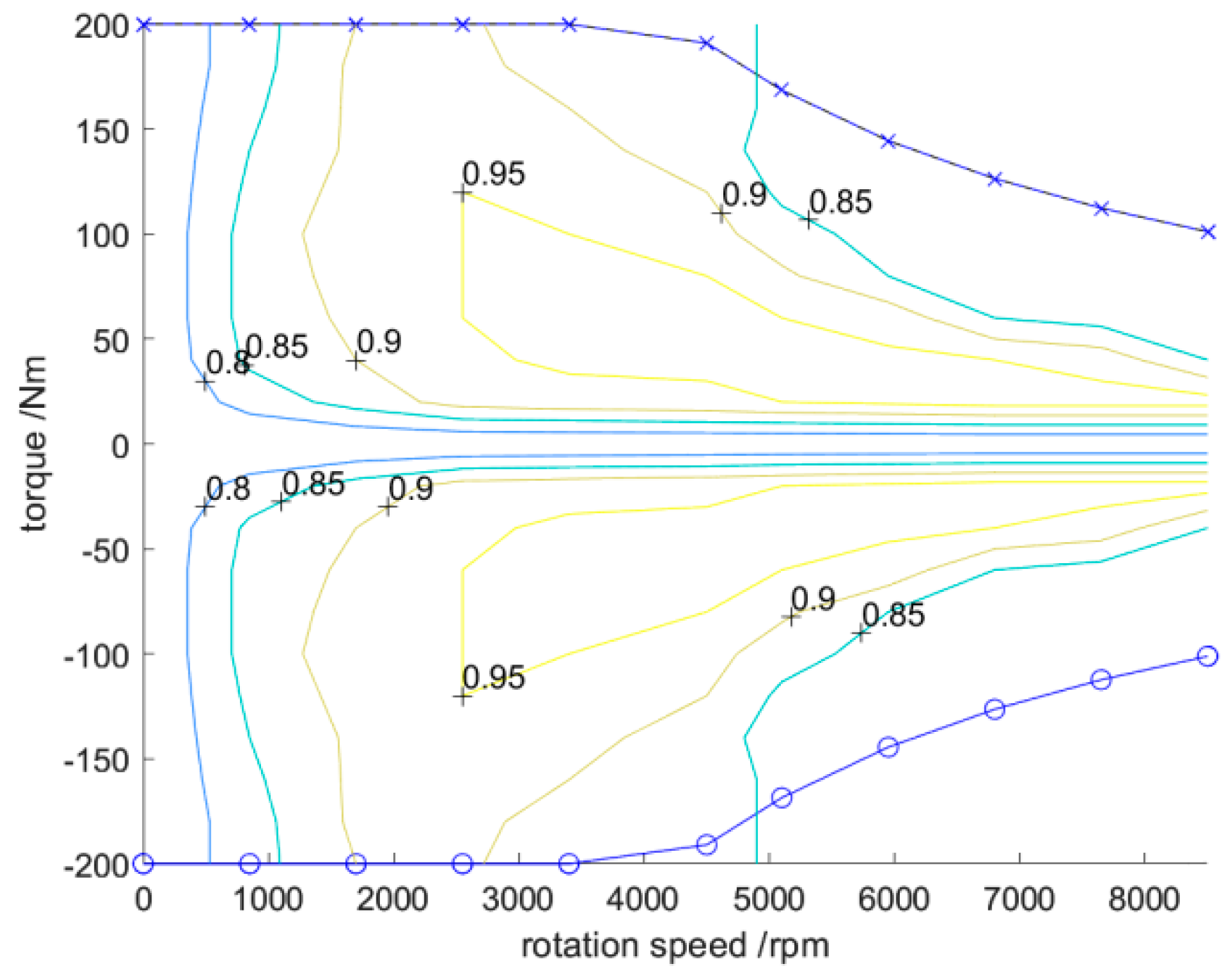
The MAP diagram of the engine is shown in Figure 4. We can know the distribution of their efficiency curves when the motor is used as an electric motor and generator. At the same time, it is also possible to obtain the values of the parameters of the motor; for example, we can know that its maximum motor torque is 200 , the maximum speed is about 8500 and the rated speed is about 4500 .
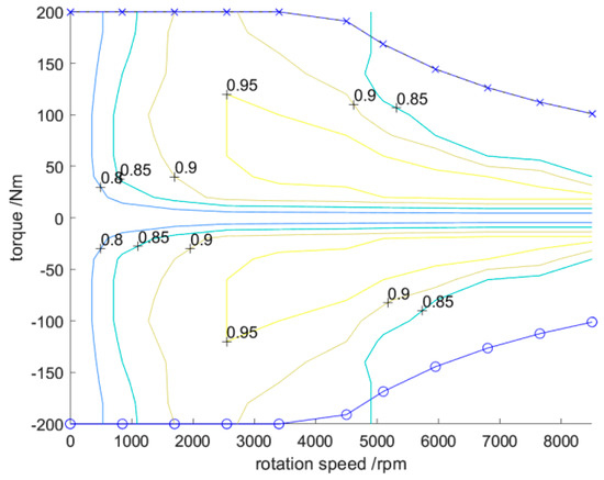
Figure 4.
Motor MAP diagram.
2.5. Vehicle Dynamics Modelling
Fuel cell vehicles are subject to five main forces during driving. These forces include thrust or braking force, rolling resistance, air resistance, ramp resistance and acceleration resistance, and their relationship to each other is as follows.
where is the tractive or braking force, is the rolling friction coefficient of the wheels, is the mass of the car, is the acceleration due to gravity, is the angle of slope of the road surface, is the air density, is the air resistance coefficient, is the windward area, is the speed of the car, and is the acceleration of the car.
3. Hybrid Energy Management Strategies
3.1. Power Following Strategy
The core of PFS is to keep the SOC of a battery in the optimal range. If the SOC is lower than the desired value, the fuel cell provides power as the sole energy source and the battery stops working and receives a charge; if the SOC is higher than the desired value, the battery starts discharging until the SOC is close to the desired value again. The PFS can be divided into the drive mode and brake mode control strategies.
3.1.1. Control Strategy in Drive Mode
When the car initially starts, the power demand of the whole vehicle is supplied by the lithium battery alone, as it takes longer for the fuel cell to start. At this time:
where is the overall vehicle demand power, is the fuel cell output power, and is the lithium battery output power.
When the car is driving normally, the power demand of the vehicle and the state of the power battery can help to determine whether the two power sources work together or take turns. In this case, the output power of the fuel cell is the main source, and the power battery plays the role of “peak shaving and valley filling” with the main power source.
- 1.
- When the SOC value is lower than the minimum SOC value
The SOC of the power battery is low, and its power output should be minimised, and all the energy required by the vehicle is supplied by the fuel cell, which also recharges the lithium battery. At this point, the power distribution satisfies the following equation:
where is the maximum output power of the fuel cell.
Battery charging mode:
- 2.
- When the SOC value is the ideal SOC value
The power battery is in an ideal state of charge, at which point PEMFC should be operating in the high-efficiency range as much as possible to meet the power requirements of the whole vehicle and improve the efficiency of the fuel cell. When additional power is required, the power battery can provide peak power supplementation, and when residual energy is available, the power battery can also provide energy recovery. At this time, the power distribution satisfies the following equation:
where is the minimum output power of the fuel cell.
The battery output power value is:
- 3.
- When the SOC value is higher than the maximum SOC value
If the SOC of the power battery is too high, the demanded power of the whole vehicle will be provided by the battery, and the fuel cell will operate at a lower power. This promotes the consumption of the power battery charge while keeping the SOC within a certain range.
3.1.2. Control Strategy in Braking Mode
When the braking intensity is low, the engine can fully absorb the braking energy and use it to charge the power battery; when the braking intensity is high, the power battery cannot fully absorb the regenerative braking energy, and the excess energy is dissipated by the mechanical braking system through friction into thermal energy. In this state, the power relationship is:
The PFS consists of four modules: the fuel cell on/off control module, the source-generated power calculation module, the SOC power correction module, and the fuel cell operating-point-determination module.
- Fuel cell turn-on and turn-off control module: handling the start–stop process of a fuel cell;
- Source-generated power calculation module: based on the vehicle’s demanded pow-er , the demanded output power of the fuel cell before regulation is calculated;
- SOC power correction module: regulating the demanded output power of the fuel cell;
- Fuel cell operating-point-determination module: it is mainly responsible for protecting the fuel cell, limiting the power output, making it work in the region of high efficiency, improving the life of the fuel cell and ensuring its normal operation.
3.2. Shortcomings of the PFS
Compared to the thermostat control strategy, the PFS can effectively solve the problem of frequent start–stop occurrences of the fuel cell, thus prolonging its life and improving the economy of the whole vehicle. However, this strategy also has some shortcomings. Considering only the power correction of the battery’s SOC can cause the fuel cell to operate in an inefficient region, which may have an impact on the economy of the vehicle as a whole. The shortcomings of the above PFS are analysed in detail below.
The following is the calculation of the demanded output power of the fuel cell after SOC correction, as shown in Equations (16) and (17):
In Equation (16), is the output power required by the fuel cell after SOC correction, ; is the demanded output power of the fuel cell before SOC correction, ; is the corrected power of the fuel cell, .
In Equation (17), is the correction coefficient, which is positive. is the maximum value of the battery’s SOC and is the minimum value of the SOC set in the control strategy. The main purpose of power correction is to keep the SOC in the range of and to avoid overcharging and overdischarging of the power battery. This will optimise the operating point of the battery, and thus enhance the lifetime of the power battery. However, since the correction factor is a constant value, there may be a decrease in the output operating point efficiency of the fuel cell after power correction. For example, if is 22 , the efficiency at this point is 60%; after correction, the actual output power of the fuel cell may be 16 , and the corresponding efficiency drops to 53%. Therefore, the fuel cell output power corrected by considering only the battery’s SOC may cause the operating points of the fuel cell to be distributed in a low-efficiency region, thus affecting the economy of the whole vehicle to a certain extent.
3.3. PFS-FLCS Hybrid Strategy
In order to solve the defects of PFS, we propose a hybrid PFS-FLCS energy management control strategy. This strategy uses FLCS to take the lithium battery SOC and the fuel cell demand output power before SOC regulation as input variables and the correction coefficient as the only output variable when performing SOC power correction, and the fuzzy control framework is shown in Figure 5. The main feature of the PFS-FLCS hybrid control strategy is to adjust the correction coefficients in real time, so that the correction coefficients are changed from constant values and adjusted according to real-time conditions of the output quantity. By formulating fuzzy rules, the SOC is maintained within a certain range, and the fuel cell output power is corrected to a higher-efficiency operating point, thus solving the problem of vehicle economy.
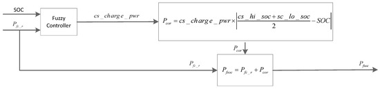
Figure 5.
Fuzzy control framework.
A fuzzy controller consists of fuzzy inputs, a fuzzification interface, an inference rule base, a defuzzification interface and fuzzy outputs. At present, the main methods of defuzzification are the maximum membership method, centre of gravity method and weighted average method. Compared with the maximum membership method, the centre of gravity method has a smoother output inference control, even if the output changes corresponding to a small change in the input signal. Therefore, we select the centre of gravity method (centroid) as the defuzzification method.
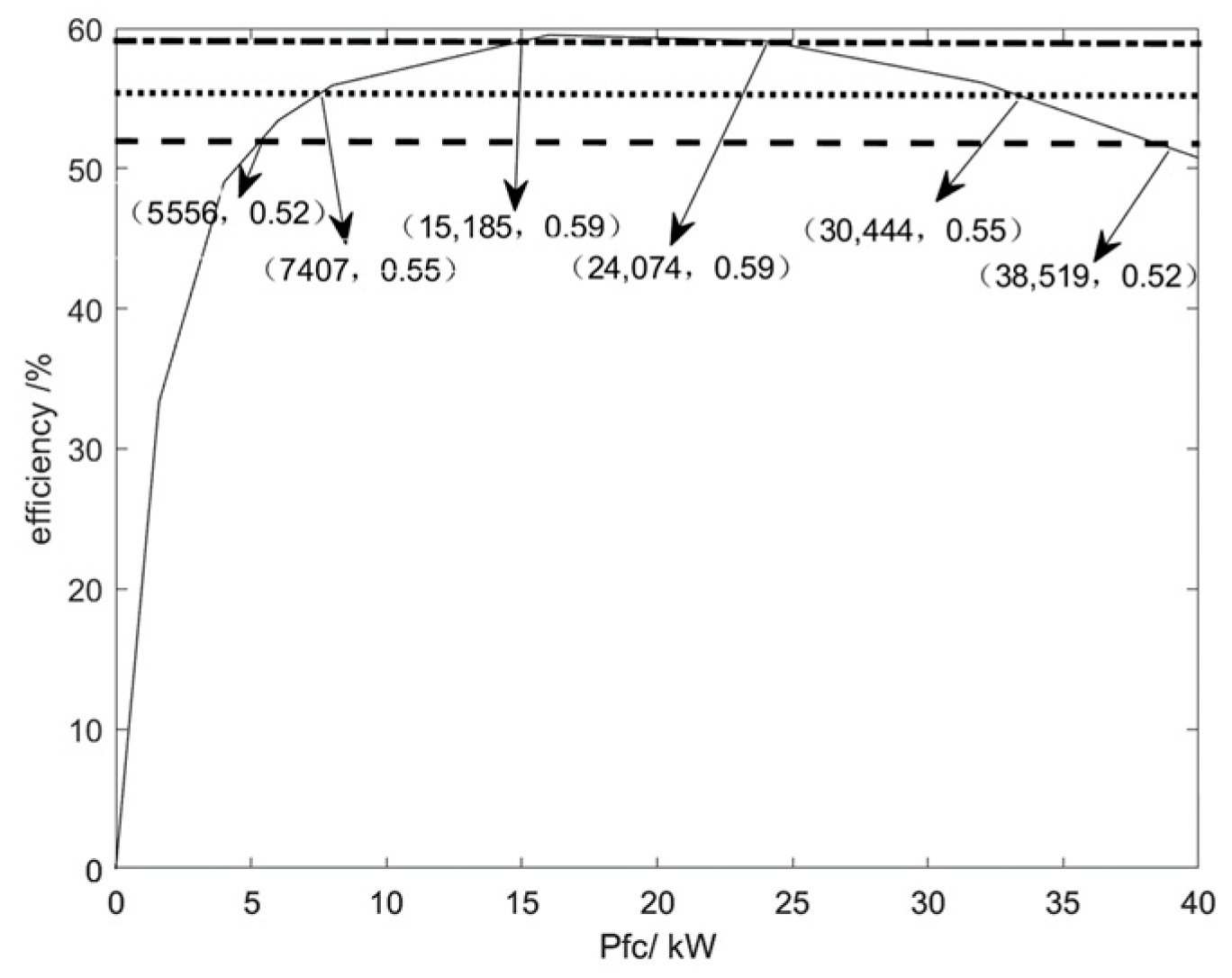
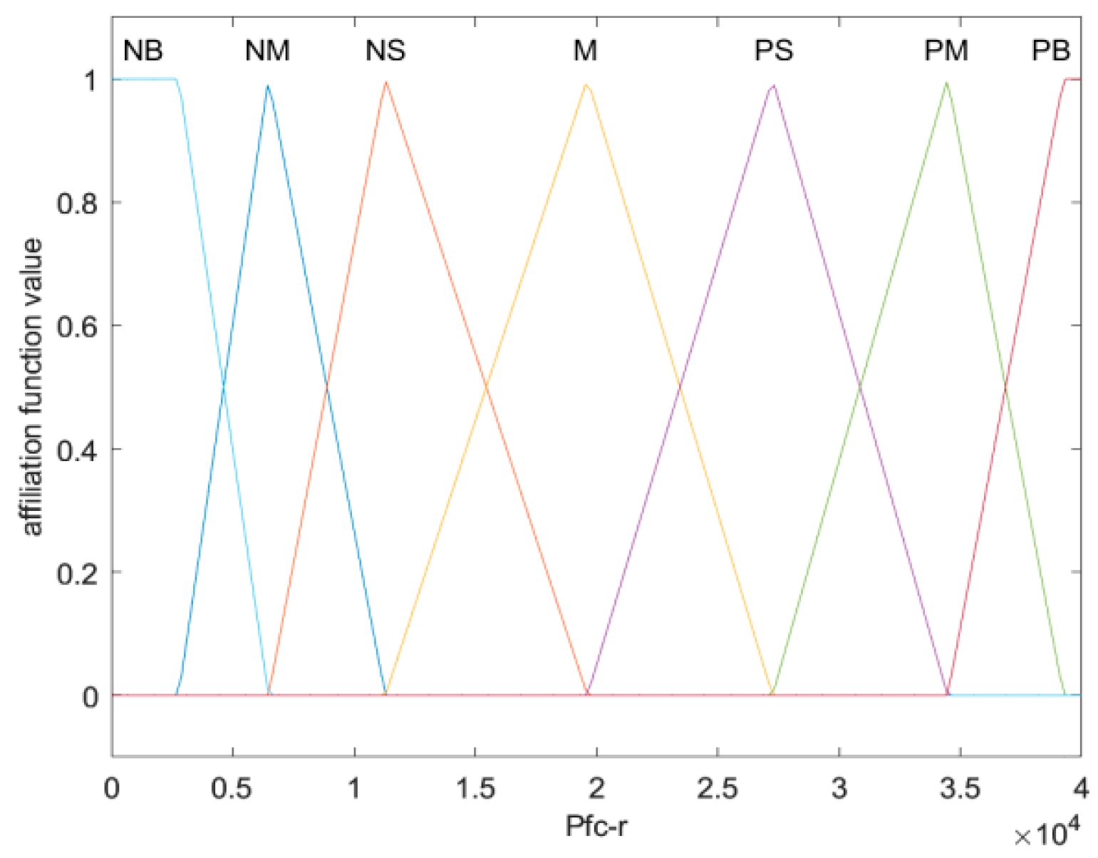
Formulation of the membership function for the input variable : from the three horizontal lines corresponding to the efficiencies of 0.52, 0.55, and 0.59, the efficiency curve of the 40 fuel cell is divided into seven intervals, and the midpoint of each interval segment corresponds to the value of the membership function of 1. The divisions of the operating intervals and the membership functions of the input variables are shown in Table 4 and Figure 6, Figure 7, Figure 8 and Figure 9.
Table 4.
Working interval and midpoint of interval.

Figure 6.
PEMFC workspace division.
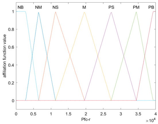
Figure 7.
Membership function for fuel cell output power.
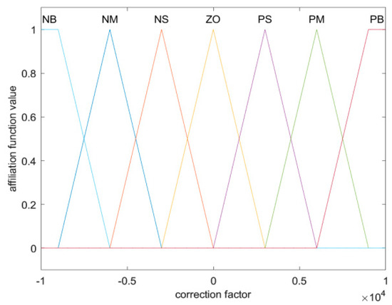
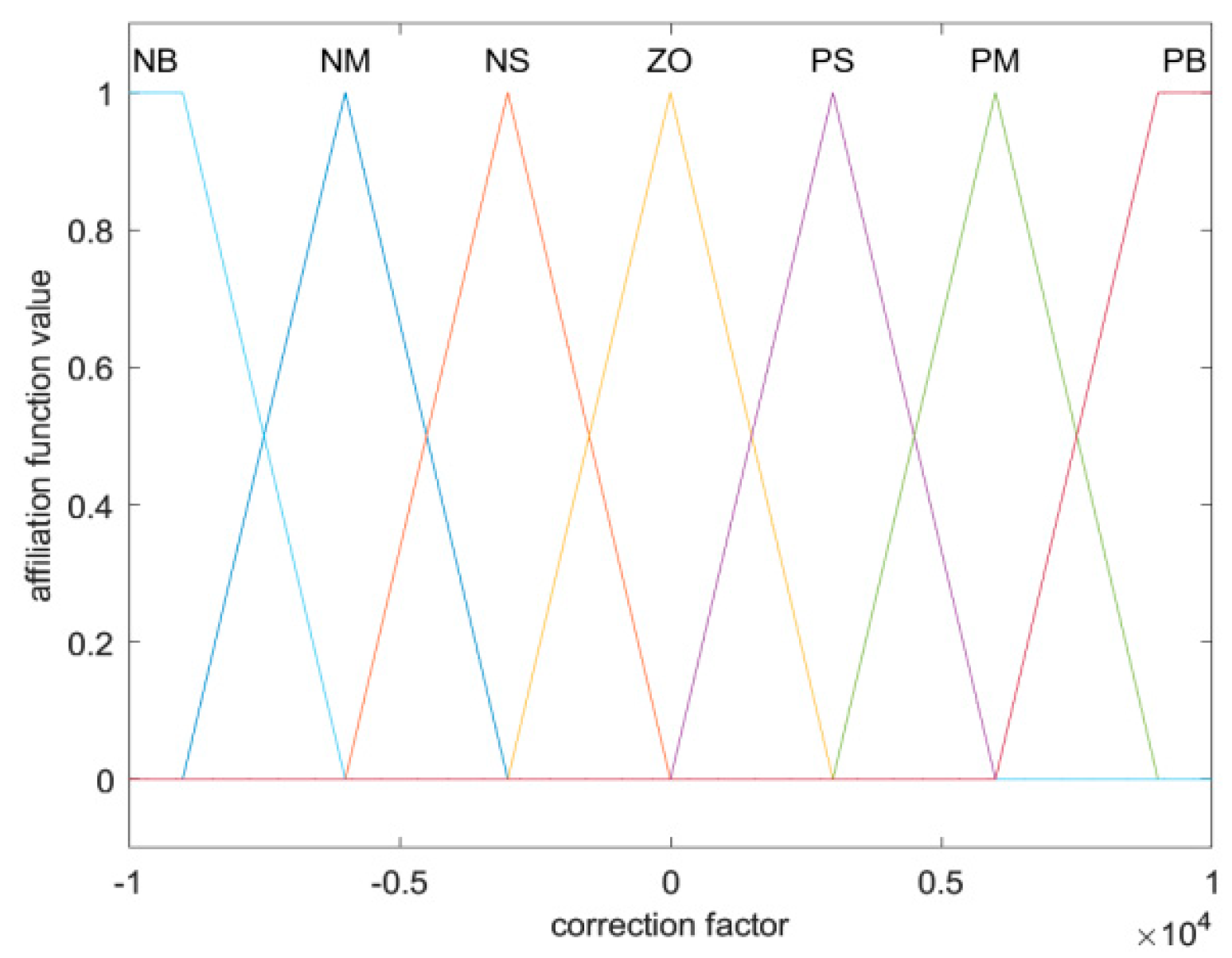
Figure 8.
Correction coefficient membership function.
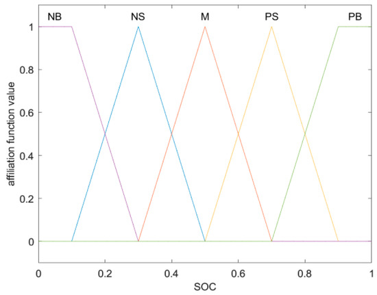
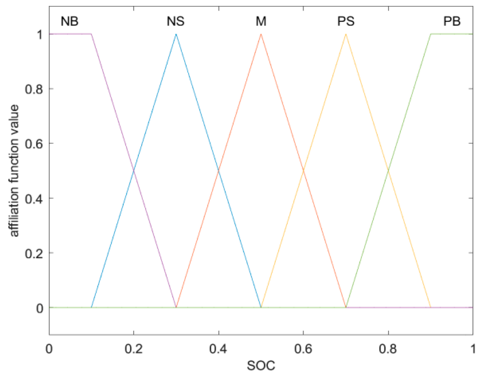
Figure 9.
Battery SOC membership function.
From the purpose of satisfying the SOC correction of lithium battery and the operating point of the fuel cell in the high-efficiency region, the fuzzy rules formulated are shown in Table 5. When the is small and the SOC of the battery is low, the correction coefficient will take a large value to keep the operating point of the fuel cell in the high-efficiency region and at the same time charge the battery to keep its SOC within a certain range. When the is large and the SOC of the battery is high, the correction coefficient will take a large negative value, which will reduce the actual output power of the fuel cell to work in the high-efficiency region, and the remaining power will be supplemented by the battery to correct the SOC.
Table 5.
Fuzzy control rule base.
4. Experiments and Analyses
4.1. Simulation Model Building
The PFS consists of four modules: the fuel cell on/off control module, the source-generated power calculation module, the SOC power correction module, and the fuel cell operating-point-determination module. According to the basic principle of the PFS, as shown in Figure 10, the control strategy model was established in Matlab/Simulink. The inputs of the PFS model are the power required by the whole vehicle (power req’d by bus) and the power battery SOC, and the output is the output power that the fuel cell can actually provide (engine pwr).

Figure 10.
Power following strategy model.
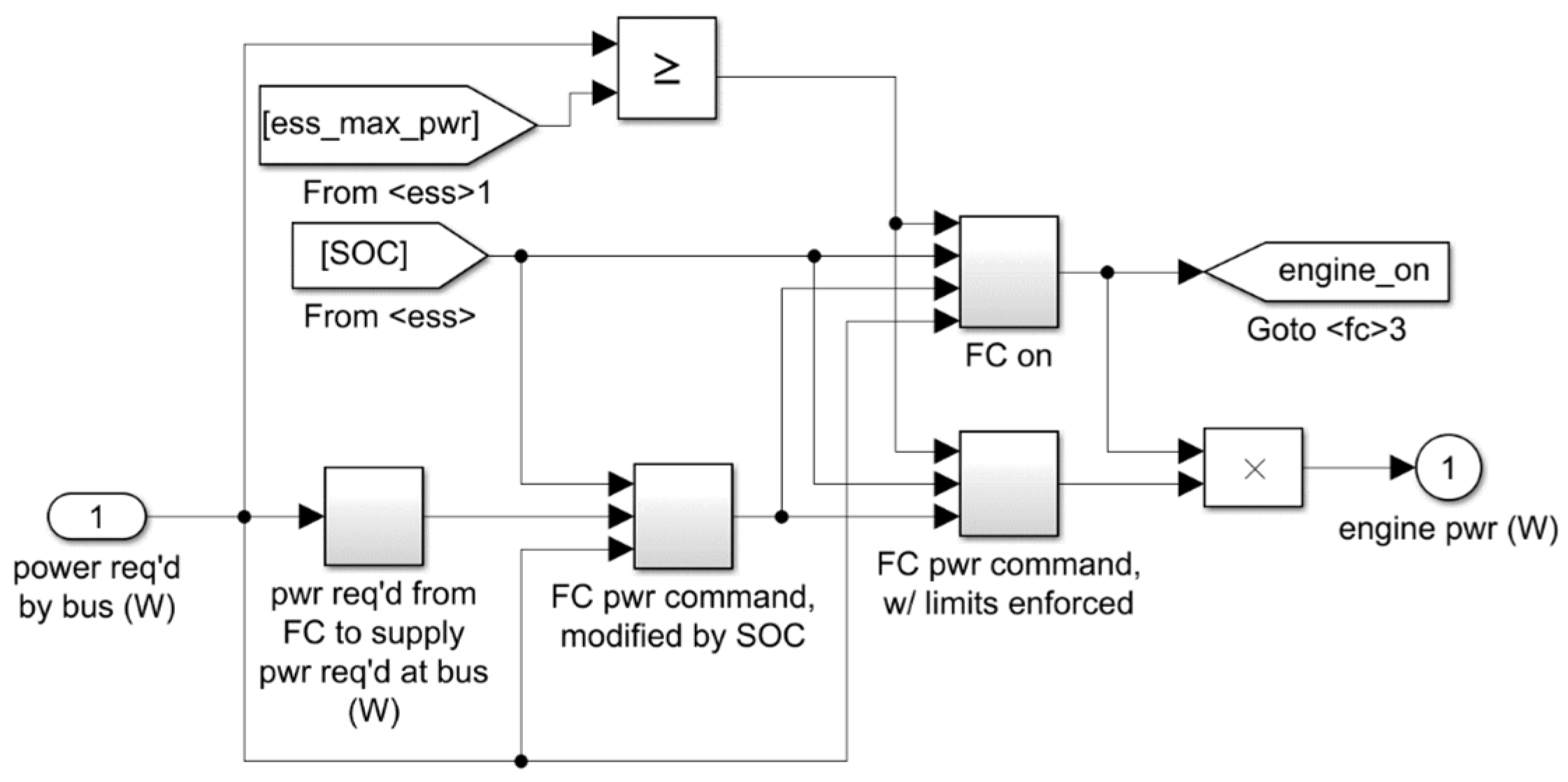
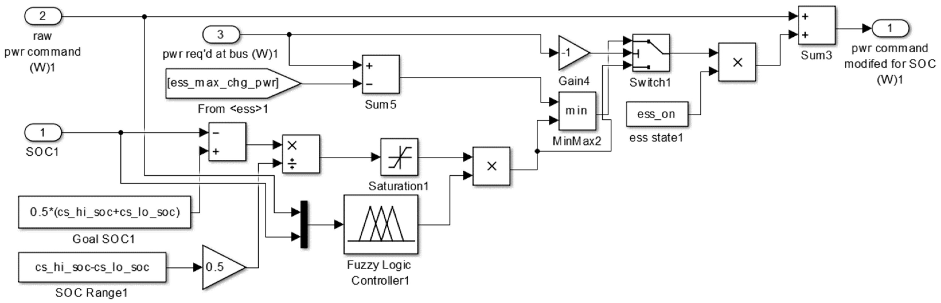
The hybrid control strategy of PFS-FLCS is improved on the basis of the SOC correction module of the PFS, and the dynamic adjustment of the correction coefficients is realized by adding an FLCS. The SOC power correction module in the PFS-FLCS is shown in Figure 11. On the basis of the SOC correction module of the PFS, we takes the demanded output power of the fuel cell before the SOC correction and the SOC of the lithium battery as the input variables of the fuzzy controller, and we adjust the correction coefficients in real time through the fuzzy reasoning process in order to realize the precise control of the fuel cell output power and the effective correction of the SOC. The module has three inputs: input variable 1 is the SOC, input variable 2 is the fuel cell demanded output power before SOC correction, input variable 3 is the whole-vehicle demanded power, and the output of the correction module is the demanded output power of the fuel cell after correcting the SOC.

Figure 11.
SOC power correction module in PFS-FLCS hybrid strategy.
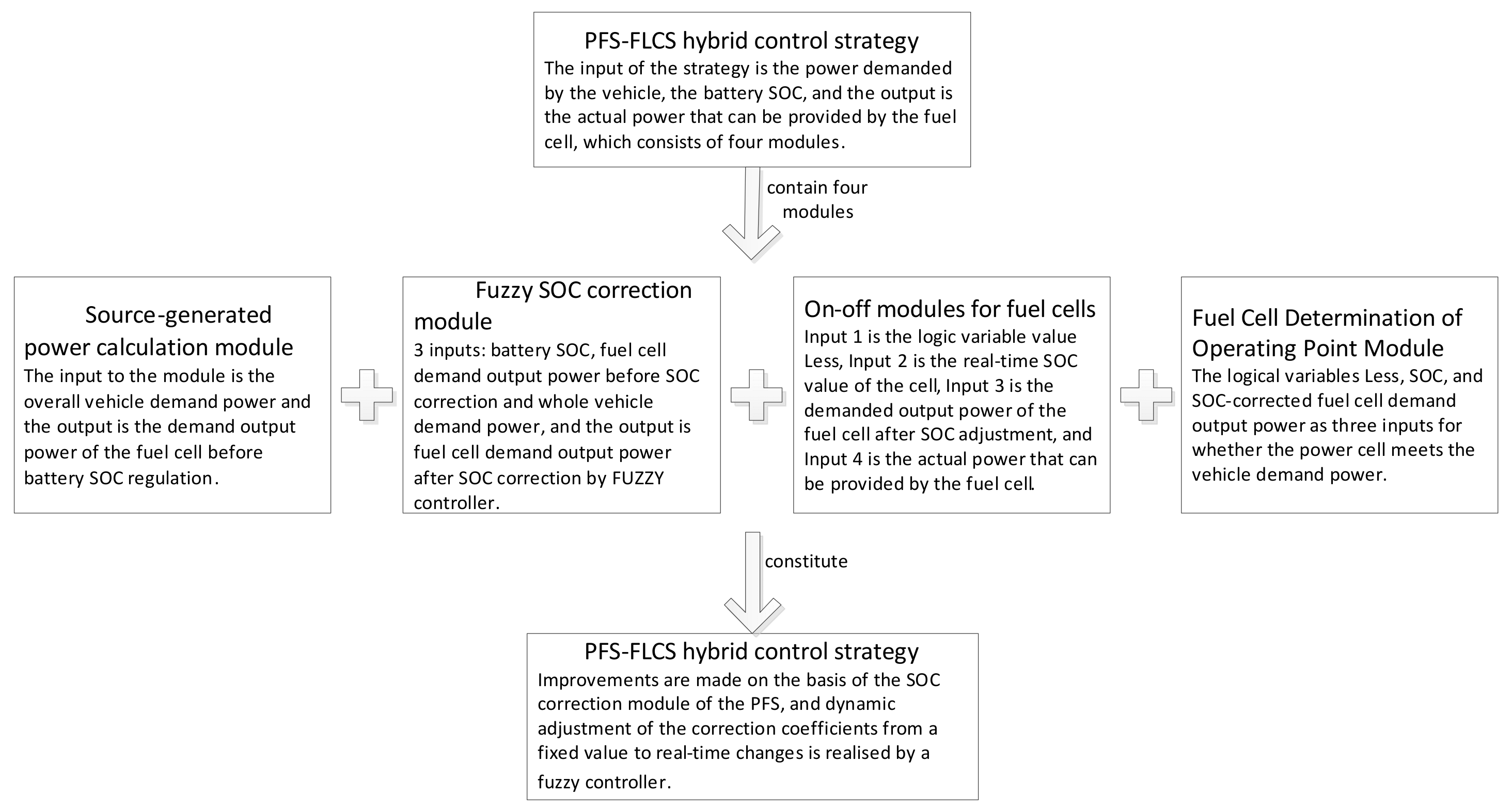
The PFS-FLCS hybrid strategy model was built by replacing the SOC power correction module in the PFS with the improved SOC power correction module in Figure 11. The control framework of the PFS-FLCS strategy is shown in Figure 12.
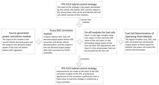
Figure 12.
Basic framework of the PFS-FLCS hybrid control strategy model.
MATLAB R2014b was used to complete the simulation verification of the whole-vehicle energy management. The fuzzy controller for the EMS was designed using the fuzzy logic toolbox as shown in Figure 11. Through the secondary development of Advisor 2002 software, we were able to complete the construction of the FCHEV model [30], and each module in the model represented different components of the vehicle. The transfer of information between modules was indicated by arrows. We obtained the power demand of the whole vehicle according to the cycle condition and the energy flow passes through the vehicle, wheels, main gearbox, transmission, engine and bus module in order; finally, the power required by the bus was distributed by the fuel cell and lithium battery together. The whole-vehicle simulation experiment was completed, and the whole-vehicle performance, fuel cell performance degradation and whole-vehicle economy were analysed. The simulation model of the FCHEVs and the meaning of each module are shown in Figure 13 and Table 6.
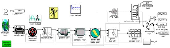
Figure 13.
Vehicle top-level simulation model.
Table 6.
Notes for the modules.
4.2. Selection of Simulation Conditions and Dynamics Validation
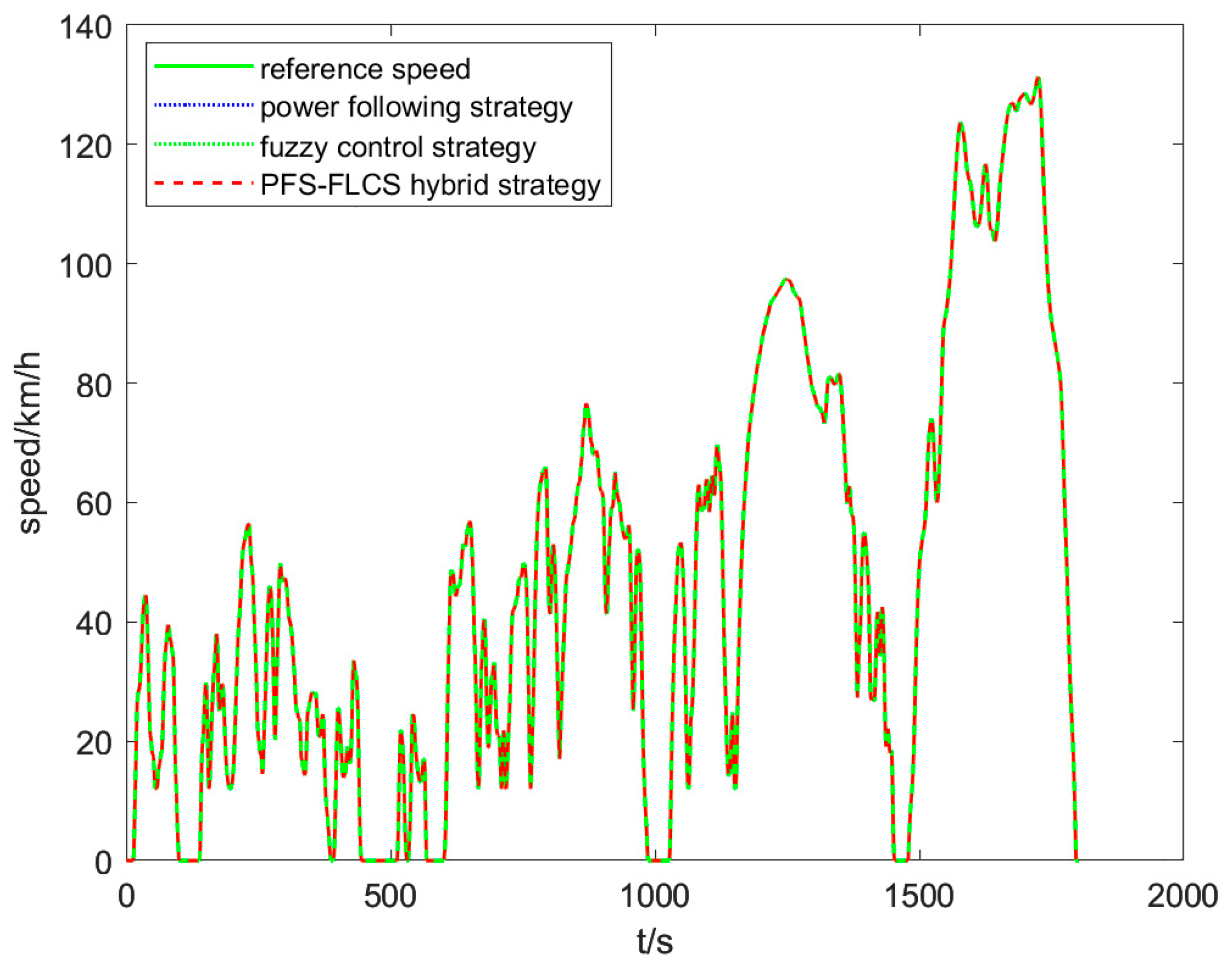
The WLTC cycle conditions are divided into four simulation conditions: low speed, medium speed, high speed and ultra-high speed, with no periodic acceleration and deceleration, large speed fluctuations and little idling, which better reflect the real driving scenarios that are sometimes fast and sometimes slow; the four conditions are selected as the simulation conditions. Figure 14 shows that the PFS-FLCS hybrid control strategy proposed in this paper, as well as the PFS and the FLCS, are able to achieve speed following for the WLTC cycle condition, and all of them are able to meet the performance index of the whole vehicle.
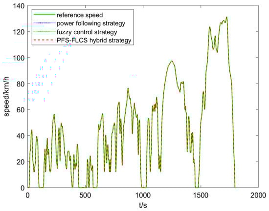
Figure 14.
Vehicle dynamics validation with different control strategies under WLTC.
4.3. Comparison and Analysis of Simulation Results
In order to verify the effectiveness and feasibility of the proposed energy management strategies, the PFS-FLCS hybrid control strategy, the FLCS, and the PFS were embedded into the control strategy module in Advisor, respectively, and the secondary development of the whole-vehicle simulation model was completed, so as to compare and analyse the simulation results of energy management strategies.
From the simulation results of the power battery SOC in Figure 15, it can be seen that under the three control strategies, the fluctuation range of the power battery SOC can be maintained at 0.4–0.8, which can meet the requirements of the vehicle’s strategy and avoid overcharging and overdischarging of the power battery, which is conducive to improving the life of the battery. At the time when the power demand of the vehicle is not large (0-1483 s), the fuel cell provides most of the power. At the same time, there is excess output power for battery charging, so the SOC increases slowly. In the vehicle bus power demand peak (1483 s), the fuel cell works in the high-efficiency region to meet the vehicle demand power; at the same time, the SOC decreases, and the battery and the fuel cell provide the vehicle demand power together, playing the role of “peak shaving to fill the valley”. In the whole vehicle working condition interval (0–1141 s), compared with the FLCS and PFS, the PFS-FLCS hybrid control strategy has a smaller range of SOC fluctuations and a smoother SOC output, which avoids a wide range of fluctuations in the SOC of the battery and is of great significance for extending the life of the battery.
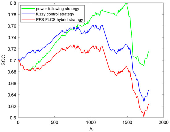
Figure 15.
The simulation results of battery SOC with different control strategies.
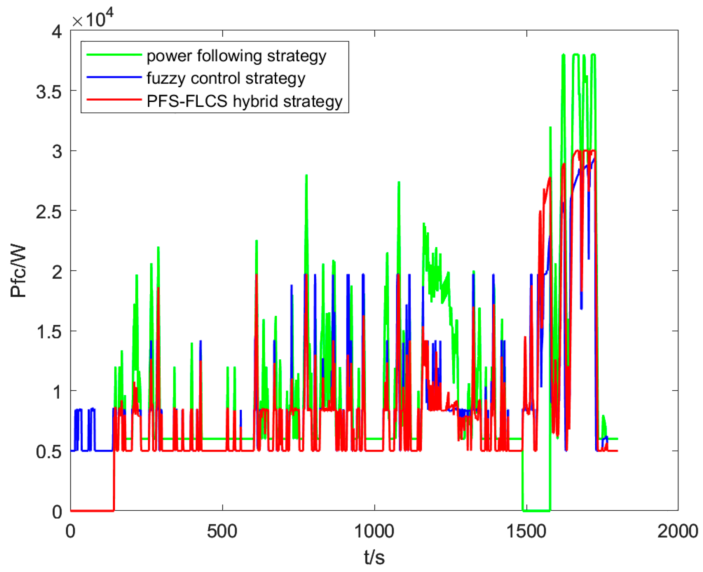
The simulation results of the fuel cell output power under the PFS-FLCS hybrid control strategy, the FLCS and the PFS are shown below.
As can be seen in Figure 16, in general, the fluctuation range of the fuel cell output power under the PFS-FLCS is smaller than that of the PFS and FLCS, and the number of starts and stops of the fuel cell is changed from 1 to 0 times. In the whole-vehicle operating state interval (120–1476 s), the average value of the fuel cell output power under the PFS-FLCS is 8105.2 , and the average value of the output power under the PFS and FLCS are 9490.8 and 8466.1 , respectively. The variation rate of the fuel cell output power based on the PFS-FLCS control strategy is reduced by 14.6% and 5.1%, respectively, which is conducive to prolonging the service life of the fuel cell and improving its durability. In the whole-vehicle working condition (1476–1750 s), the hybrid-based control strategy increases its fuel cell output power compared with FLCS, and the elevated fuel cell output power is conducive to the output operating point of the fuel cell falling in the high-efficiency zone, further reducing hydrogen consumption, improving the whole-vehicle economy and prolonging its service life.

Figure 16.
The simulation results of PEMFC output power.
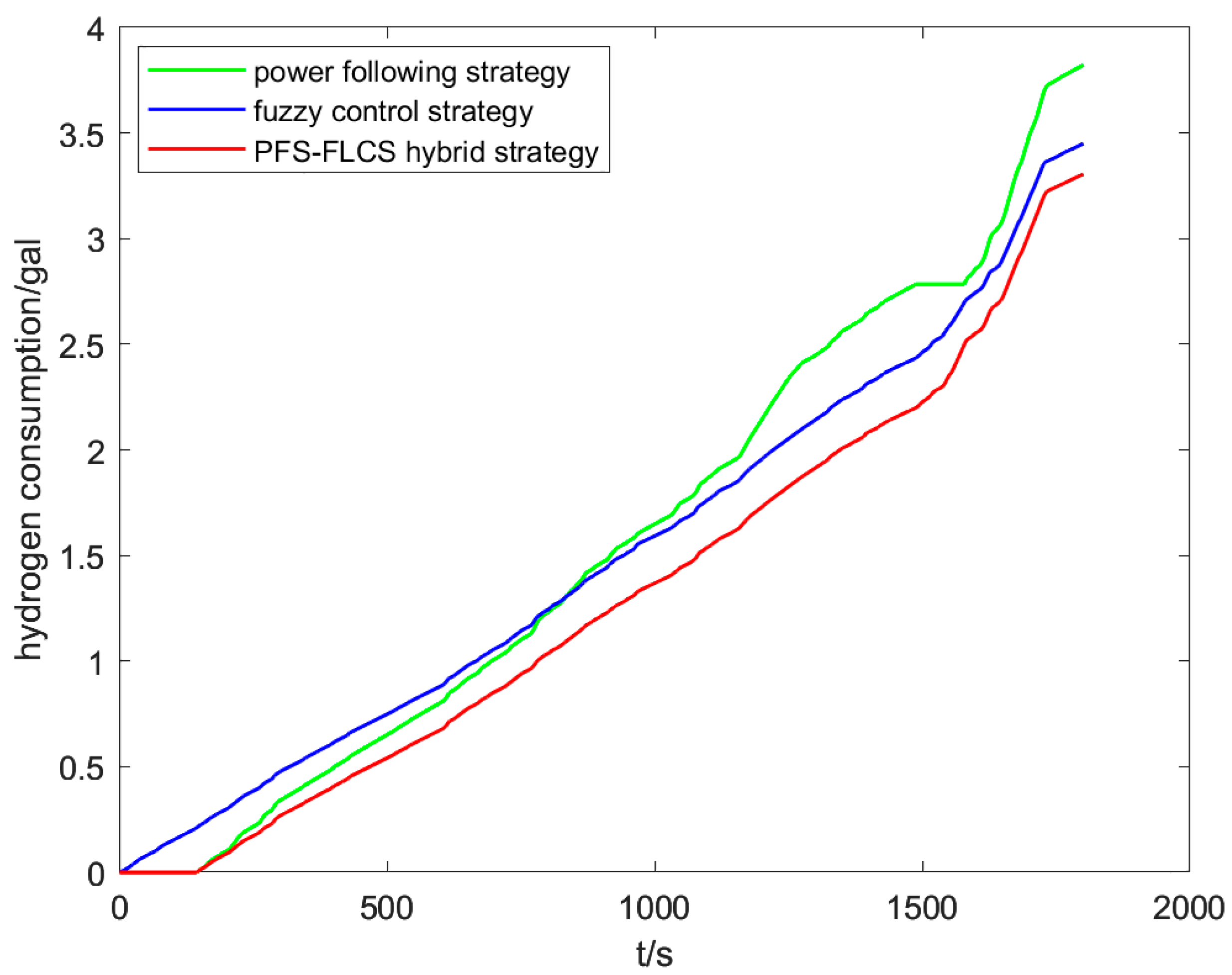
The hydrogen consumption of the fuel cell vehicle under the three control strategies is shown in Figure 17 below.
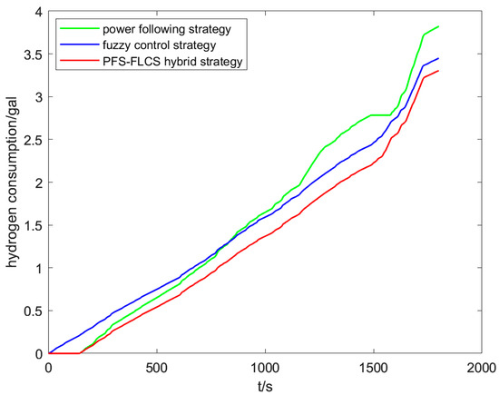
Figure 17.
Hydrogen consumption with different control strategies.
The hydrogen consumption per 100 km was used to evaluate the economy of the FCHEV, and by comparing the hydrogen consumption under different control strategies, it can be seen from Table 7 and Table 8 that the hydrogen consumption of the vehicle is 62.2 and 56.1 under PFS and FLCS control strategies, respectively. The hydrogen consumption based on PFS-FLCS is 53.8 . Compared with the PFS and FLCS, the hydrogen consumption per 100 km based on the PFS-FLCS hybrid control strategy is reduced by 13.5% and 4.1%, respectively, so the energy management strategy based on the PFS-FLCS hybrid control can significantly improve the economy of the whole vehicle.
Table 7.
Rate of change of hydrogen consumption per 100 km; average fuel cell output power based on PFS-FLCS strategy.
Table 8.
Simulation results.
5. Conclusions and Outlook
This paper presents a hybrid energy management strategy in conjunction with the conventional PFS and FLCS to improve the economy and fuel cell durability issues of FCHEVs with two energy sources. The strategy adopts the FLCS to correct the output power of the fuel cell to the efficient operating point based on the SOC of the lithium battery. The important conclusions and future outlook are as follows:
- The proposed PFS-FLCS hybrid energy management strategy can meet the requirements of vehicle dynamics and can achieve speed following for WLTC, and the PFS-FLCS hybrid control strategy has a smaller range of SOC fluctuation degree and a smoother SOC output compared with the FLCS and PFS, which avoids a wide range of fluctuation of the battery’s SOC and is of great significance for extending the service life of the battery.
- The proposed PFS-FLCS hybrid energy management control strategy distributes the working points of the fuel cell in the high-efficiency zone by using an FLCS to adjust the correction coefficients in real time, which reduces the hydrogen consumption during the driving process and is of great importance to improve the economy of the whole vehicle.
- Compared with PFS and FLCS, the output power variability of the fuel cell based on the PFS-FLCS strategy is reduced by 14.6% and 5.1%, respectively, which is conducive to prolonging the service life of the fuel cell and improving its durability. Its 100 km hydrogen consumption is reduced by 13.5% and 4.1%, respectively, so the energy management strategy based on the PFS-FLCS hybrid control can significantly improve the overall vehicle economy.
- In this paper, the simulation verification of the PFS-FLCS is completed only under WLTC driving conditions, and it is hoped that the simulation verification analysis can be carried out under other typical conditions, which will improve the applicability of the hybrid strategy. The validation analysis of each energy management strategy is limited to the simulation level, and a future research work is expected to be able to carry out the hardware-in-the-loop simulation of the whole vehicle.
Author Contributions
Conceptualization, W.L. and K.Z.; methodology, K.Z.; software, K.Z.; validation, K.Z.; formal analysis, all authors; investigation, all authors; writing—original draft preparation, W.L.; writing—review and editing, Z.L. and W.L.; visualization, K.Z.; project administration, W.L. and Z.L.; funding acquisition, W.L. and Z.L. All authors have read and agreed to the published version of the manuscript.
Funding
This research was funded by the National Natural Science Foundation of China, grant number 62263001; the Natural Science Foundation of Guangxi, grant number 2020GXNSFDA238011; Open Fund Project of Guangxi Key Laboratory of Automation Detection Technology and Instrument, grant number YQ21203; and Open Fund Project of Key Laboratory of AI and Information Processing (Hechi University) of Education Department of Guangxi, grant number 2022GXZDSY002.
Data Availability Statement
Data are contained within the article.
Acknowledgments
The authors would like to thank all the anonymous reviewers for their insightful comments and constructive suggestions.
Conflicts of Interest
The authors declare no conflict of interest.
References
- Bendjedia, B.; Rizoug, N.; Boukhnifer, M. Energy management strategies for a fuel-cell/battery hybrid power system. Proc. Inst. Mech. Eng. Part I J. Syst. Control Eng. 2023, 237, 704–716. [Google Scholar] [CrossRef]
- Zhao, F. Research on the Development Strategy of FAW-Volkswagen New Energy Vehicles. Master’s Thesis, Jilin University, Changchun, China, 2018. [Google Scholar]
- Zhu, D.; Wang, X.; Li, Y. Research progress on energy management strategies for hybrid electric vehicles. Mech. Des. Manuf. 2020, 57, 293–296. [Google Scholar]
- Kandidayeni, M.; Trovao, J.; Soleymani, M. Towards health-aware energy management strategies in fuel cell hybrid electric vehicles: A review. Int. J. Hydrogen Energy 2022, 47, 10021–10043. [Google Scholar]
- Sulaiman, N.; Hannan, M.; Mohamed, A. A review on energy management system for fuel cell hybrid electric vehicle: Issues and challenges. Renew. Sustain. Energy Rev. 2015, 52, 802–814. [Google Scholar] [CrossRef]
- Minsoo, J.; Ciobotaru, M.; Agelidis, V. R Design and Implementation of Digital Control in a Fuel Cell System. IEEE Trans. Industr. Inform. 2013, 9, 1158–1166. [Google Scholar]
- Wang, Y.; Yu, Q.; Wang, X. Adaptive optimal energy management strategy for fuel cell vehicles considering performance degradation. J. Transp. Eng. 2022, 22, 190–204. [Google Scholar]
- Kang, J.; Guo, Y.; Liu, J. Rule-based Energy Management Strategies for a Fuel Cell-Battery Hybrid Locomotive. In Proceedings of the 2020 IEEE 4th Conference on Energy Internet and Energy System Integration (EI2), Wuhan, China, 30 October–1 November 2020; IEEE: Piscataway, NJ, USA, 2020. [Google Scholar]
- Xi, L.; Zhang, X.; Geng, C. Energy management strategy optimization of extended-range electric vehicle based on dynamic programming. J. Traffic Transp. Eng. 2018, 18, 9. [Google Scholar]
- Gim, J.; Kim, M.; Ahn, C. Energy Management Control Strategy for Saving Trip Costs of Fuel Cell/Battery Electric Vehicles. Energies 2022, 15, 2131. [Google Scholar] [CrossRef]
- Sabri, M.; Danapalasingam, K.; Rahmat, M. A review on hybrid electric vehicles architecture and energy management strategies. Renew. Sustain. Energy Rev. 2016, 53, 1433–1442. [Google Scholar] [CrossRef]
- Zhang, Y.; Chu, L.; Guo, Z.; Hou, Z.; Zhang, Y.; Guo, C. An energy management strategy based on dynamic programming to improve working conditions of fuel cells. In Proceedings of the 2021 5th CAA International Conference on Vehicular Control and Intelligence (CVCI), Tianjin, China, 29–31 October 2021; pp. 1–5. [Google Scholar]
- Tao, F.; Zhu, L.; Ji, B. Energy Management Strategy Using Equivalent Consumption Minimization Strategy for Hybrid Electric Vehicles. Secur. Commun. Netw. 2020, 2020, 6642304. [Google Scholar] [CrossRef]
- Zhang, F.; Wang, L.; Coskun, S. Computationally Efficient Energy Management in Hybrid Electric Vehicles Based on Approximate Pontryagin’s Minimum Principle. World Electron. Veh. J. 2020, 11, 65. [Google Scholar] [CrossRef]
- Zhou, M.; Liu, W.; Zhang, Y. Research on energy management of hybrid power system in fuel cell vehicles. Int. J. Electron. 2022, 14, 134–149. [Google Scholar] [CrossRef]
- Essoufi, M.; Hajji, B.; Rabhi, A. Fuzzy Logic based Energy Management Strategy for Fuel Cell Hybrid Electric Vehicle. In Proceedings of the 2020 International Conference on Electrical and Information Technologies (ICEIT), Rabat, Morocco, 4–7 March 2020; pp. 1–7. [Google Scholar]
- Yang, H.; Chen, J.; Li, G.; Xiao, C. Power Optimization of Hydrogen Fuel Cell Vehicle Based on Genetic and Fuzzy Algorithm. In Proceedings of the 2021 40th Chinese Control Conference (CCC), Shanghai, China, 26–28 July 2021; pp. 5853–5856. [Google Scholar]
- Zhou, S.; Cui, Q.; Zhang, M. Research on fuel cell vehicle energy management system using composite fuzzy logic control. Power Gener. Technol. 2018, 39, 554–560. [Google Scholar]
- Tao, J.; Zhang, R.; Wang, N. GA based FC/SC fuzzy energy management system considering H_2 consumption and loading variation. In Proceedings of the 36th Chinese Control Conference, Dalian, China, 26–28 July 2017. [Google Scholar]
- Li, Q. Research on Energy Management Strategy of Fuel Cell Vehicle Based on Multi-Objective Optimisation. Master’s Thesis, Hefei University of Technology, Heifei, China, 2021. [Google Scholar]
- Cao, N. Design and Energy Management of on-Board Fuel Cell Hybrid Power System. Master’s Thesis, Southwest Jiaotong University, Chengdu, China, 2017. [Google Scholar]
- Sulaiman, N.; Hannan, M.; Mohamed, A. Optimization of energy management system for fuel-cell hybrid electric vehicles: Issues and recommendations. Appl. Energy 2018, 43, 2061–2079. [Google Scholar] [CrossRef]
- Chen, W.; Yan, Y.; Li, Q. State machine-based control strategy for fuel cell hybrid power system. J. Southwest Jiaotong Univ. 2019, 54, 663–670. [Google Scholar]
- Ding, A.; Zhang, C.; Shen, Y. Research on improved state machine energy management strategy for fuel cell vehicles. Mech. Manuf. Autom. 2021, 50, 182–184. [Google Scholar]
- Wang, Q. Research on Power System Design and Energy Management of Electric-Electric Hybrid Fuel Cell Vehicle. Master’s Thesis, Huazhong University of Science and Technology, Wuhan, China, 2019. [Google Scholar]
- Lin, C.; Luo, W.; Lan, H. Research on Multi-Objective Compound Energy Management Strategy Based on Fuzzy Control for FCHEV. Energies 2022, 15, 1721. [Google Scholar] [CrossRef]
- Deng, H.; Zhang, Y.; Fang, R.; Pei, Z. Study on Fuel Cell Vehicle Power System Selection and Simulation. In Proceedings of the 2019 IEEE 4th Advanced Information Technology, Electronic and Automation Control Conference (IAEAC), Chengdu, China, 20–22 December 2019; pp. 2382–2385. [Google Scholar]
- Divakaran, A.; Minakshi, M.; Bahri, P. Rational design on materials for developing next generation lithium-ion secondary battery. Prog. Solid State Chem. 2021, 62, 100298. [Google Scholar] [CrossRef]
- Divakaran, A.; Hamilton, D.; Manjunatha, K. Design, Development and Thermal Analysis of Reusable Li-Ion Battery Module for Future Mobile and Stationary Applications. Energies 2020, 13, 1477. [Google Scholar] [CrossRef]
- Zeng, X.; Gong, W. ADVISOR 2002 Electric Vehicle Simulation and Redevelopment Application, 1st ed.; Machinery Industry Press: Heibei, China, 2014; pp. 100–110. [Google Scholar]


Disclaimer/Publisher’s Note: The statements, opinions and data contained in all publications are solely those of the individual author(s) and contributor(s) and not of MDPI and/or the editor(s). MDPI and/or the editor(s) disclaim responsibility for any injury to people or property resulting from any ideas, methods, instructions or products referred to in the content. |
© 2023 by the authors. Licensee MDPI, Basel, Switzerland. This article is an open access article distributed under the terms and conditions of the Creative Commons Attribution (CC BY) license (https://creativecommons.org/licenses/by/4.0/).