

An Open-Circuit Fault Diagnosis System Based on Neural Networks in the Inverter of Three-Phase Permanent Magnet Synchronous Motor (PMSM)


Abstract
1. Introduction
2. Proposed Open-Circuit Fault Diagnosis System
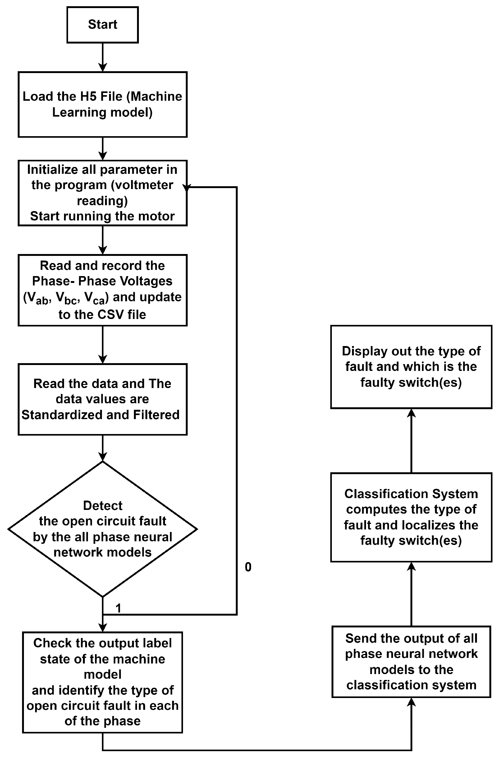
2.1. Behaviour of the Open-Circuit Fault Diagnosis System
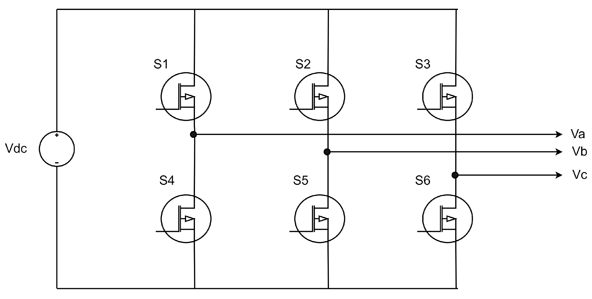
2.2. Type of Open-Circuit Fault
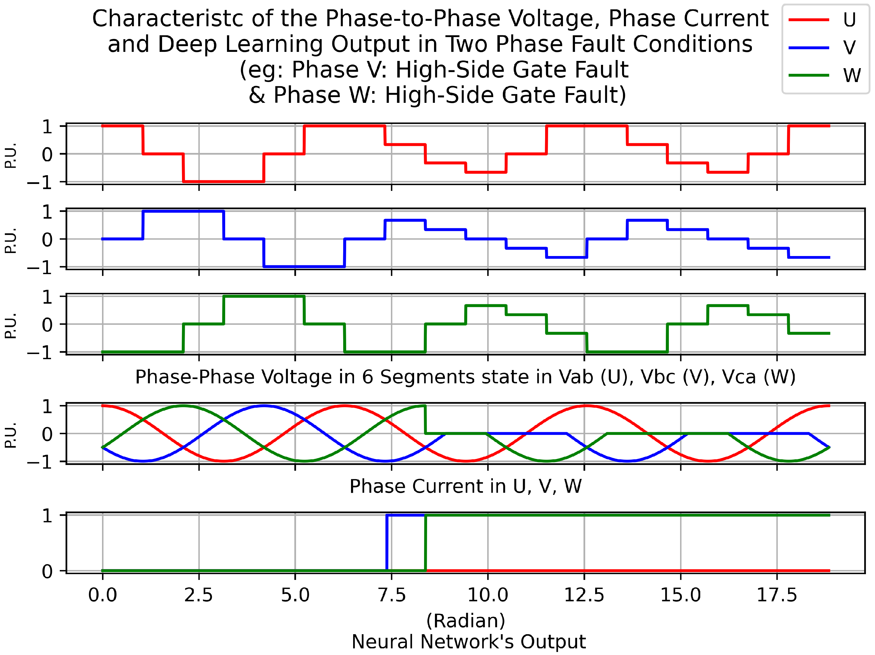
2.3. Type of Phase Fault
3. Methodology of Developing Proposed Open-Circuit Fault Diagnosis System (OCFDS)
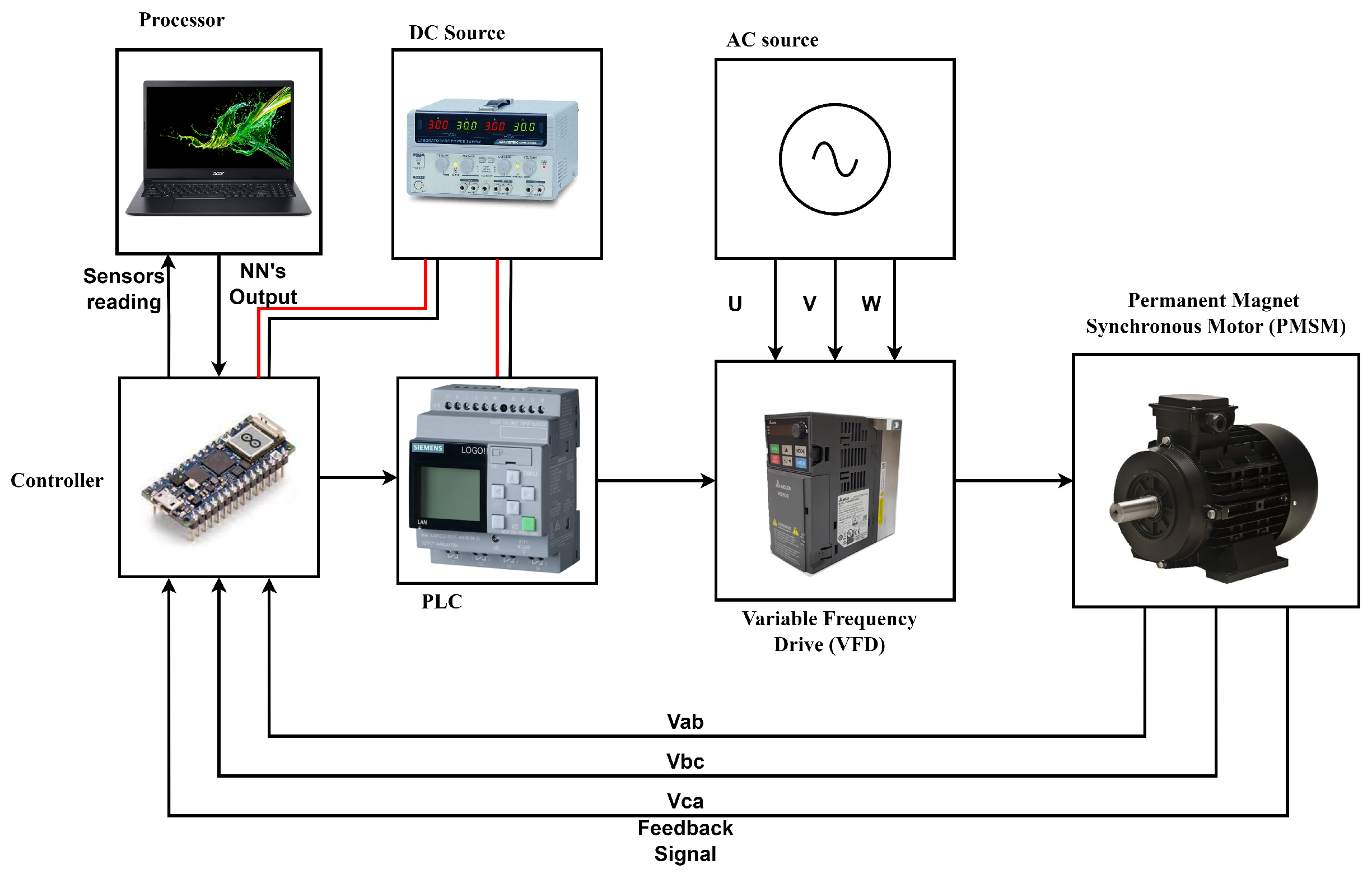
3.1. Setup Arrangement and Flow of the Proposed Open-Circuit Fault Diagnosis System
3.2. Arrangement of the Neural Network
4. Result and Discussion
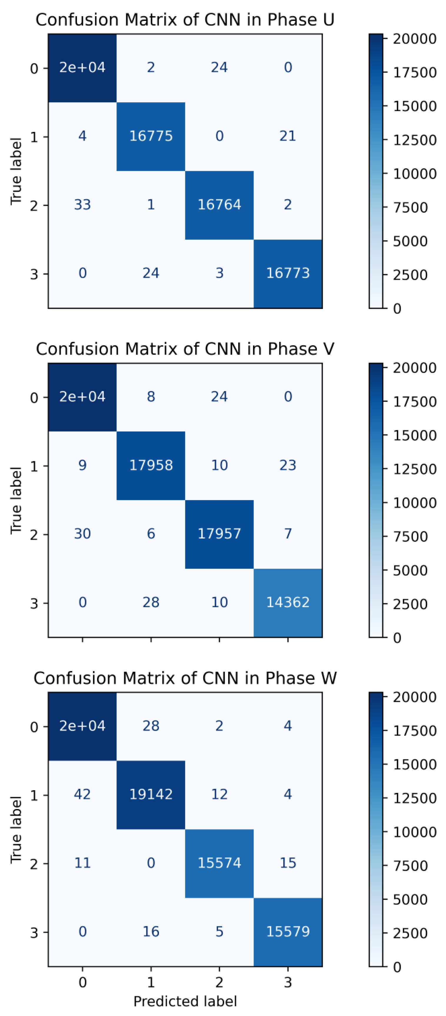
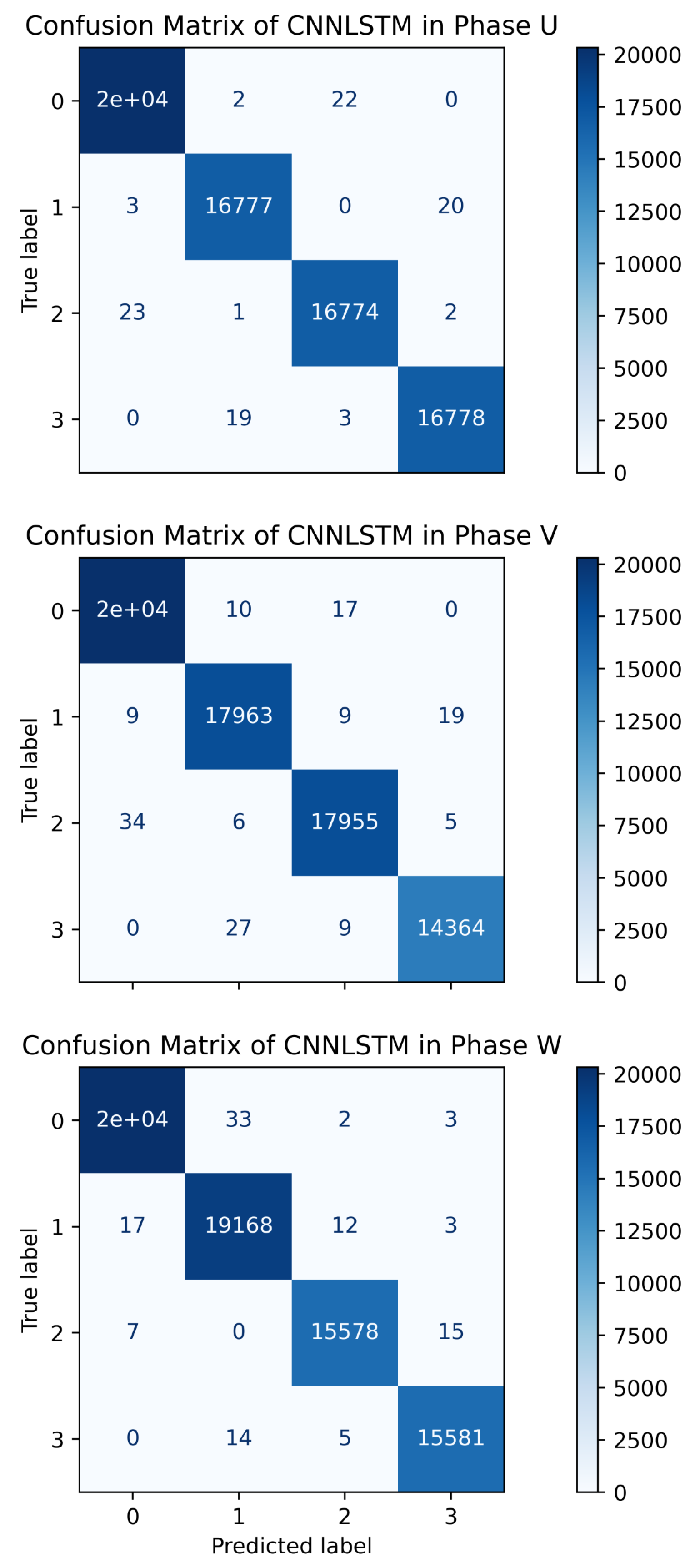
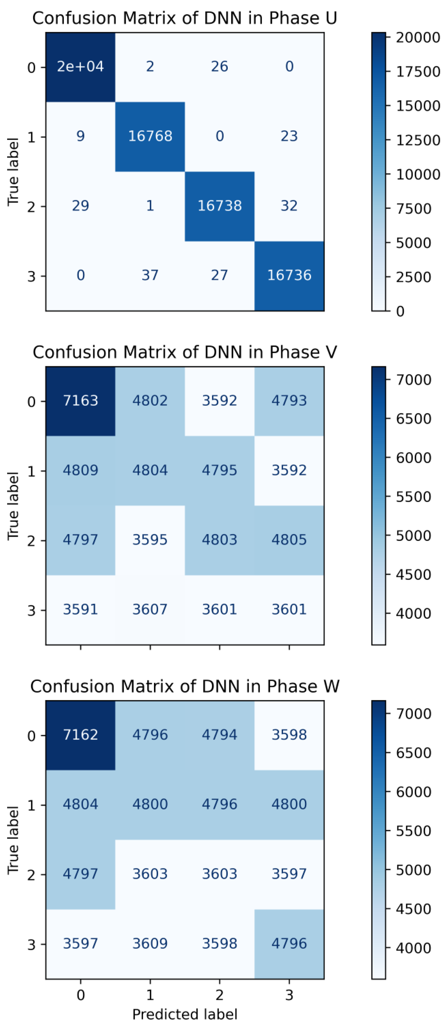
4.1. Performance of Different Neural Network Architectures in Phase Neural Networks of Open-Circuit Fault Diagnosis System
4.2. Response of the Proposed Open-Circuit Fault Diagnosis System
5. Conclusions
Author Contributions
Funding
Data Availability Statement
Conflicts of Interest
References
- Fan, Y.; Cui, R.; Zhang, A. Torque Ripple Minimization for Inter-Turn Short-Circuit Fault Based on Open-Winding Five Phase FTFSCW-IPM Motor for Electric Vehicle Application. IEEE Trans. Veh. Technol. 2020, 69, 282–292. [Google Scholar] [CrossRef]
- Cao, C.; Wang, Z.; Duan, C.; Wang, X. Fault-Tolerant Control of Dual Three-Phase PMSM Drives with Inter-Turn Short-Circuit Fault. In Proceedings of the 2021 IEEE 13th International Symposium on Diagnostics for Electrical Machines, Power Electronics and Drives (SDEMPED), Dallas, TX, USA, 22–25 August 2021. [Google Scholar] [CrossRef]
- Kumar, P.H.; Lakhimsetty, S.; Somasekhar, V.T. An Open-End Winding BLDC Motor Drive With Fault Diagnosis and Autoreconfiguration. IEEE J. Emerg. Sel. Top. Power Electron. 2020, 8, 3723–3735. [Google Scholar] [CrossRef]
- Choi, U.M.; Lee, J.S.; Blaabjerg, F.; Lee, K.B. Open-Circuit Fault Diagnosis and Fault-Tolerant Control for a Grid-Connected NPC Inverter. IEEE Trans. Power Electron. 2015, 31, 7234–7247. [Google Scholar] [CrossRef]
- Salehifar, M.; Arashloo, R.S.; Moreno-Equilaz, J.M.; Sala, V.; Romeral, L. Fault Detection and Fault Tolerant Operation of a Five Phase PM Motor Drive Using Adaptive Model Identification Approach. IEEE J. Emerg. Sel. Top. Power Electron. 2014, 2, 212–223. [Google Scholar] [CrossRef]
- Guefack, F.L.T.; Kiselev, A.; Kuznietsov, A. Improved Detection of Inter-turn Short Circuit Faults in PMSM Drives using Principal Component Analysis. In Proceedings of the 2018 International Symposium on Power Electronics, Electrical Drives, Automation and Motion (SPEEDAM), Amalfi, Italy, 20–22 June 2018. [Google Scholar] [CrossRef]
- Orlowska-Kowalska, T.; Wolkiewicz, M.; Pietrzak, P.; Skowron, M.; Ewert, P.; Tarchala, G.; Krzysztofiak, M.; Kowalski, C.T. Fault Diagnosis and Fault-Tolerant Control of PMSM Drives–State of the Art and Future Challenges. IEEE Access 2022, 10, 59979–60024. [Google Scholar] [CrossRef]
- Wang, X.; Wang, Z.; Xu, Z.; Cheng, M.; Wang, W.; Hu, Y. Comprehensive Diagnosis and Tolerance Strategies for Electrical Faults and Sensor Faults in Dual Three-Phase PMSM Drives. IEEE Trans. Power Electron. 2019, 34, 6669–6684. [Google Scholar] [CrossRef]
- Ullah, Z.; Hur, J. Analysis of Inter-Turn-Short Fault in an FSCW IPM Type Brushless Motor Considering Effect of Control Drive. IEEE Trans. Ind. Appl. 2020, 56, 1356–1367. [Google Scholar] [CrossRef]
- Halder, S.; Bhat, S.; Bhaumik, C.; Rakshit, R. Stator Inter-Turn Fault Diagnosis in Permanent Magnet Synchronous Motor. In Proceedings of the 2020 IEEE First International Conference on Smart Technologies for Power, Energy and Control (STPEC), Nagpur, India, 25–26 September 2020. [Google Scholar] [CrossRef]
- Wang, X.; Wang, Z.; Gu, M.; Xiao, D.; He, J.; Emadi, A. Diagnosis-Free Self-Healing Scheme for Open-Circuit Faults in Dual Three-Phase PMSM Drives. IEEE Trans. Power Electron. 2020, 35, 12053–12071. [Google Scholar] [CrossRef]
- Gou, B.; Ge, X.; Wang, S.; Feng, X.; Kuo, J.B.; Habetler, T.G. An Open-Switch Fault Diagnosis Method for Single-Phase PWM Rectifier Using a Model-Based Approach in High-Speed Railway Electrical Traction Drive System. IEEE Trans. Power Electron. 2016, 31, 3816–3826. [Google Scholar] [CrossRef]
- Sun, J.; Li, C.; Zheng, Z.; Wang, K.; Li, Y. A Generalized, Fast and Robust Open-Circuit Fault Diagnosis Technique for Star-connected Symmetrical Multiphase Drives. IEEE Trans. Energy Convers. 2022, 37, 1921–1933. [Google Scholar] [CrossRef]
- Chen, T.; Pan, Y. A Novel Diagnostic Method for Multiple Open-Circuit Faults of Voltage-Source Inverters Based on Output Line Voltage Residuals Analysis. IEEE Trans. Circuits Syst. II Express Briefs 2021, 68, 1343–1347. [Google Scholar] [CrossRef]
- Chen, Y.; Liang, S.; Li, W.; Liang, H.; Wang, C. Faults and Diagnosis Methods of Permanent Magnet Synchronous Motors: A Review. Appl. Sci. 2019, 9, 2116. [Google Scholar] [CrossRef]
- Jiang, C.; Liu, H.; Wheeler, P.; Wu, F.; Cai, Z.; Huo, J. A Novel Open-Circuit Fault Detection and Location for Open-End Winding PMSM Based on Differential-Mode Components. IEEE Trans. Ind. Electron. 2022, 69, 7776–7786. [Google Scholar] [CrossRef]
- Gonzalez-Prieto, I.; Duran, M.J.; Rios-Garcia, N.; Barrero, F.; Martin, C. Open-Switch Fault Detection in Five-Phase Induction Motor Drives Using Model Predictive Control. IEEE Trans. Ind. Electron. 2018, 65, 3045–3055. [Google Scholar] [CrossRef]
- Lee, H.W.; Lee, K.B. Open-Circuit Fault Diagnosis and Fault-Tolerant Operation of Dual Inverter for Open-End Winding Interior Permanent Magnet Synchronous Motor. In Proceedings of the 2022 IEEE 5th Student Conference on Electric Machines and Systems (SCEMS), Busan, Republic of Korea, 24–26 November 2022. [Google Scholar] [CrossRef]
- Xu, J.; Guo, S.; Guo, H.; Tian, X. A Novel Diagnostic Method for Single and Dual Power Switch Open-Circuit Faults of Six-Phase FTPMSM System Even in Fault Tolerant Operation. IEEE Trans. Power Electron. 2022, 37, 9777–9789. [Google Scholar] [CrossRef]
- Trabelsi, M.; Semail, E.; Nguyen, N.K.; Meinguet, F. Open-switch and open-phase real time FDI process for multiphase PM Synchronous Motors. In Proceedings of the 2016 IEEE 25th International Symposium on Industrial Electronics (ISIE), Santa Clara, CA, USA, 8–10 June 2016. [Google Scholar] [CrossRef]
- Zhou, H.; Xu, J.; Chen, C.; Tian, X.; Liu, G. Disturbance-Observer-Based Direct Torque Control of Five-Phase Permanent Magnet Motor Under Open-Circuit and Short-Circuit Faults. IEEE Trans. Ind. Electron. 2021, 68, 11907–11917. [Google Scholar] [CrossRef]
- Zhang, Z.; Luo, G.; Zhang, Z.; Tao, X. A hybrid diagnosis method for inverter open-circuit faults in PMSM drives. CES Trans. Electr. Mach. Syst. 2020, 4, 180–189. [Google Scholar] [CrossRef]
- Xu, S.; Chen, X.; Liu, F.; Wang, H.; Chai, Y.; Zheng, W.X.; Chen, H. A Novel Adaptive SMO-Based Simultaneous Diagnosis Method for IGBT Open-Circuit Faults and Current Sensor Incipient Faults of Inverters in PMSM Drives for Electric Vehicles. IEEE Trans. Instrum. Meas. 2023, 72, 1–15. [Google Scholar] [CrossRef]
- Huang, W.; Du, J.; Hua, W.; Lu, W.; Bi, K.; Zhu, Y.; Fan, Q. Current-Based Open-Circuit Fault Diagnosis for PMSM Drives with Model Predictive Control. IEEE Trans. Power Electron. 2021, 36, 10695–10704. [Google Scholar] [CrossRef]
- Ke, Z.; Pan, J.; Na, R.; Potty, K.; Zhang, J.; Wang, J.; Xu, L. Single-Submodule Open-Circuit Fault Diagnosis for a Modular Multi-level Converter Using Artificial Intelligent-based Techniques. In Proceedings of the 2019 IEEE Applied Power Electronics Conference and Exposition (APEC), Anaheim, CA, USA, 17–21 March 2019. [Google Scholar] [CrossRef]
- Geng, Z.; Wang, Q.; Han, Y. IGBT Open Circuit Fault Diagnosis Based on Improved Support Vector Machine. In Proceedings of the 2021 8th International Conference on Information, Cybernetics, and Computational Social Systems (ICCSS), Beijing, China, 10–12 December 2021. [Google Scholar] [CrossRef]
- Li, Z.; Gao, Y.; Zhang, X.; Wang, B.; Ma, H. A Model-Data-Hybrid-Driven Diagnosis Method for Open-Switch Faults in Power Converters. IEEE Trans. Power Electron. 2021, 36, 4965–4970. [Google Scholar] [CrossRef]
- Apsari, D.P.; Jung, J.; Lee, D.C. Open-Circuit Fault Diagnosis Based on Deep Learning for Four-Level Active Neutral-Point Clamped Inverters. In Proceedings of the 2023 11th International Conference on Power Electronics and ECCE Asia (ICPE 2023-ECCE Asia), Jeju Island, Republic of Korea, 22–25 May 2023. [Google Scholar] [CrossRef]
- Agustin, C.A.; Yu, J.t.; Lin, C.K.; Fu, X.Y. A Modulated Model Predictive Current Controller for Interior Permanent-Magnet Synchronous Motors. Energies 2019, 12, 2885. [Google Scholar] [CrossRef]
- Huang, W.; Du, J.; Hua, W.; Fan, Q. An open-circuit fault diagnosis method for PMSM drives using symmetrical and DC components. Chin. J. Electr. Eng. 2021, 7, 124–135. [Google Scholar] [CrossRef]
- Li, X.; Li, S.; Chen, W.; Shi, T.; Xia, C. A Fast Diagnosis Strategy for Inverter Open-Circuit Faults Based on the Current Path of Brushless DC Motors. IEEE Trans. Power Electron. 2023, 38, 9311–9316. [Google Scholar] [CrossRef]
- Lemma, B.D.; Pradabane, S. Control of PMSM Drive Using Lookup Table Based Compensated Duty Ratio Optimized Direct Torque Control (DTC). IEEE Access 2023, 11, 19863–19875. [Google Scholar] [CrossRef]
- Chollet, F. Deep Learning with Python, Second Edition; Manning Publications Co. LLC: New York, NY, USA, 2021; p. 400. [Google Scholar]


| State | Closed Switch | Line to Neutral Voltage | Phase to Phase Voltage | ||||
|---|---|---|---|---|---|---|---|
| VU | VV | VW | Vab | Vbc | Vca | ||
| 0 | - | 0 | 0 | 0 | 0 | 0 | 0 |
| 1 | S1, S5, S6 | 2VDC/3 | −VDC/3 | −VDC/3 | VDC | 0 | −VDC |
| 2 | S1, S2, S6 | VDC/3 | VDC/3 | −2VDC/3 | 0 | VDC | −VDC |
| 3 | S2, S4, S6 | −VDC/3 | 2VDC/3 | −VDC/3 | −VDC | VDC | 0 |
| 4 | S2, S3, S4 | −2VDC/3 | VDC/3 | VDC/3 | −VDC | 0 | VDC |
| 5 | S3, S4, S5 | −VDC/3 | −VDC/3 | 2VDC/3 | 0 | −VDC | VDC |
| 6 | S1, S3, S5 | VDC/3 | −2VDC/3 | VDC/3 | VDC | −VDC | 0 |
| 7 | - | 0 | 0 | 0 | 0 | 0 | 0 |
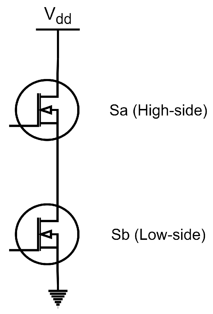
| Condition | Damaged Switch | Machine Learning State Labelling |
|---|---|---|
| Normal Condition | - | 0 |
| One switch fault | Sa | 1 |
| Sb | 2 | |
| Two switch fault | Sa and Sb | 3 |
| Phase with Fault | Machine Learning State Label | |
|---|---|---|
| Normal operation | None | 0 |
| One Phase Fault | U | 1 |
| V | 2 | |
| W | 3 | |
| Two Phases Fault | U, V | 4 |
| U, W | 5 | |
| V, W | 6 | |
| Three Phases Faults | U, V, W | 7 |
| Description (Unit) | Value |
|---|---|
| Input AC Voltage (V) | 220/230 |
| Frequency (Hz) | 100 |
| Rated Torque (Nm) | 12.8 |
| Rated Speed (rpm) | 3000 |
| Rated Current (A) | 8.6 |
| Rated Power (kW) | 4 |
| No. of Poles | 4 |
| Layer | ANN | DNN | CNN1D |
|---|---|---|---|
| 1 | Dense (50, ReLu) | Dense (50, ReLu) | Conv1D (6, 3 ReLu) |
| 2 | Flatten | Flatten | MaxPooling1D (2, ReLu) |
| 3 | Dense (4, softmax) | Dense (24, ReLu) | Flatten |
| 4 | - | Dense (12, ReLu) | Dense (16, ReLu) |
| 5 | - | Dense (4, ReLu) | Dense (4, softmax) |
| 6 | - | Dense (4, softmax) | - |
| Training Duration | - | - | - |
| Layer | LSTM | CNNLSTM | |
| 1 | LSTM (50, tanh) | Conv1D (6, 3 ReLu) | |
| 2 | Dense (50, ReLu) | MaxPooling1D (2, ReLu) | |
| 3 | Dense (25, ReLu) | Dense (50, ReLu) | |
| 4 | Dense (12, ReLu) | LSTM (50, tanh) | |
| 5 | Dense (4, ReLu) | Flatten | |
| 6 | Dense (4, softmax) | Dense (4, softmax) |
| Detection Accuracies (%) | |||
|---|---|---|---|
| Neural Networks | Phase U | Phase V | Phase W |
| ANN | 97.94 | 28.78 | 28.78 |
| CNN | 99.84 | 99.78 | 99.80 |
| CNN-LSTM | 99.87 | 99.80 | 99.80 |
| DNN | 99.74 | 28.79 | 28.78 |
| LSTM | - | - | - |
| CNN 1 | CNN 2 | CNN 3 | CNN 4 | CNN 5 | |
| Conv1D | Conv1D | Conv1D | Conv1D | Conv1D | |
| MaxPooling | MaxPooling | MaxPooling | MaxPooling | MaxPooling | |
| 1D | 1D | 1D | 1D | 1D | |
| Flatten | Flatten | Flatten | Flatten | Flatten | |
| Dense | Dense | Dense | Dense | Dense | |
| - | Dense | Dense | Dense | Dense | |
| - | - | Dense | Dense | Dense | |
| - | - | - | Dense | Dense | |
| - | - | - | - | Dense | |
| U Accuracy(%) | 99.84 | 99.84 | 99.84 | 93.61 | 99.85 |
| V Accuracy(%) | 99.71 | 99.72 | 99.78 | 99.73 | 99.75 |
| W Accuracy(%) | 97.58 | 98.11 | 99.80 | 99.85 | 99.86 |
| Average Accuracy(%) | 99.04 | 99.22 | 99.81 | 97.73 | 99.82 |
| CNN-LSTM 1 | CNN-LSTM 2 | CNN-LSTM 3 | CNN-LSTM 4 | CNN-LSTM 5 | |
| Conv1D | Conv1D | Conv1D | Conv1D | Conv1D | |
| MaxPooling | MaxPooling | MaxPooling | MaxPooling | MaxPooling | |
| 1D | 1D | 1D | 1D | 1D | |
| LSTM | Dense | Dense | Dense | Dense | |
| Flatten | LSTM | Dense | Dense | Dense | |
| Dense | Flatten | LSTM | Dense | Dense | |
| - | Dense | Flatten | LSTM | Dense | |
| - | - | Dense | Flatten | LSTM | |
| - | - | - | Dense | Flatten | |
| - | - | - | - | Dense | |
| U Accuracy(%) | 99.84 | 99.84 | 95.02 | 99.81 | 99.85 |
| V Accuracy(%) | 87.61 | 99.80 | 99.77 | 99.84 | 99.77 |
| W Accuracy(%) | 99.80 | 99.84 | 94.73 | 99.82 | 99.82 |
| Average Accuracy(%) | 95.75 | 99.83 | 96.51 | 99.82 | 99.81 |
Disclaimer/Publisher’s Note: The statements, opinions and data contained in all publications are solely those of the individual author(s) and contributor(s) and not of MDPI and/or the editor(s). MDPI and/or the editor(s) disclaim responsibility for any injury to people or property resulting from any ideas, methods, instructions or products referred to in the content. |
© 2024 by the authors. Licensee MDPI, Basel, Switzerland. This article is an open access article distributed under the terms and conditions of the Creative Commons Attribution (CC BY) license (https://creativecommons.org/licenses/by/4.0/).
Share and Cite
Chu, K.S.K.; Chew, K.W.; Chang, Y.C.; Morris, S. An Open-Circuit Fault Diagnosis System Based on Neural Networks in the Inverter of Three-Phase Permanent Magnet Synchronous Motor (PMSM). World Electr. Veh. J. 2024, 15, 71. https://doi.org/10.3390/wevj15020071
Chu KSK, Chew KW, Chang YC, Morris S. An Open-Circuit Fault Diagnosis System Based on Neural Networks in the Inverter of Three-Phase Permanent Magnet Synchronous Motor (PMSM). World Electric Vehicle Journal. 2024; 15(2):71. https://doi.org/10.3390/wevj15020071
Chicago/Turabian StyleChu, Kenny Sau Kang, Kuew Wai Chew, Yoong Choon Chang, and Stella Morris. 2024. "An Open-Circuit Fault Diagnosis System Based on Neural Networks in the Inverter of Three-Phase Permanent Magnet Synchronous Motor (PMSM)" World Electric Vehicle Journal 15, no. 2: 71. https://doi.org/10.3390/wevj15020071
APA StyleChu, K. S. K., Chew, K. W., Chang, Y. C., & Morris, S. (2024). An Open-Circuit Fault Diagnosis System Based on Neural Networks in the Inverter of Three-Phase Permanent Magnet Synchronous Motor (PMSM). World Electric Vehicle Journal, 15(2), 71. https://doi.org/10.3390/wevj15020071