
Sliding Mode Control of an Electric Vehicle Driven by a New Powertrain Technology Based on a Dual-Star Induction Machine

 ,
,  ,
,  and
and 
Abstract
1. Introduction
2. Materials and Methods
2.1. Dynamic Model of Electric Vehicle System
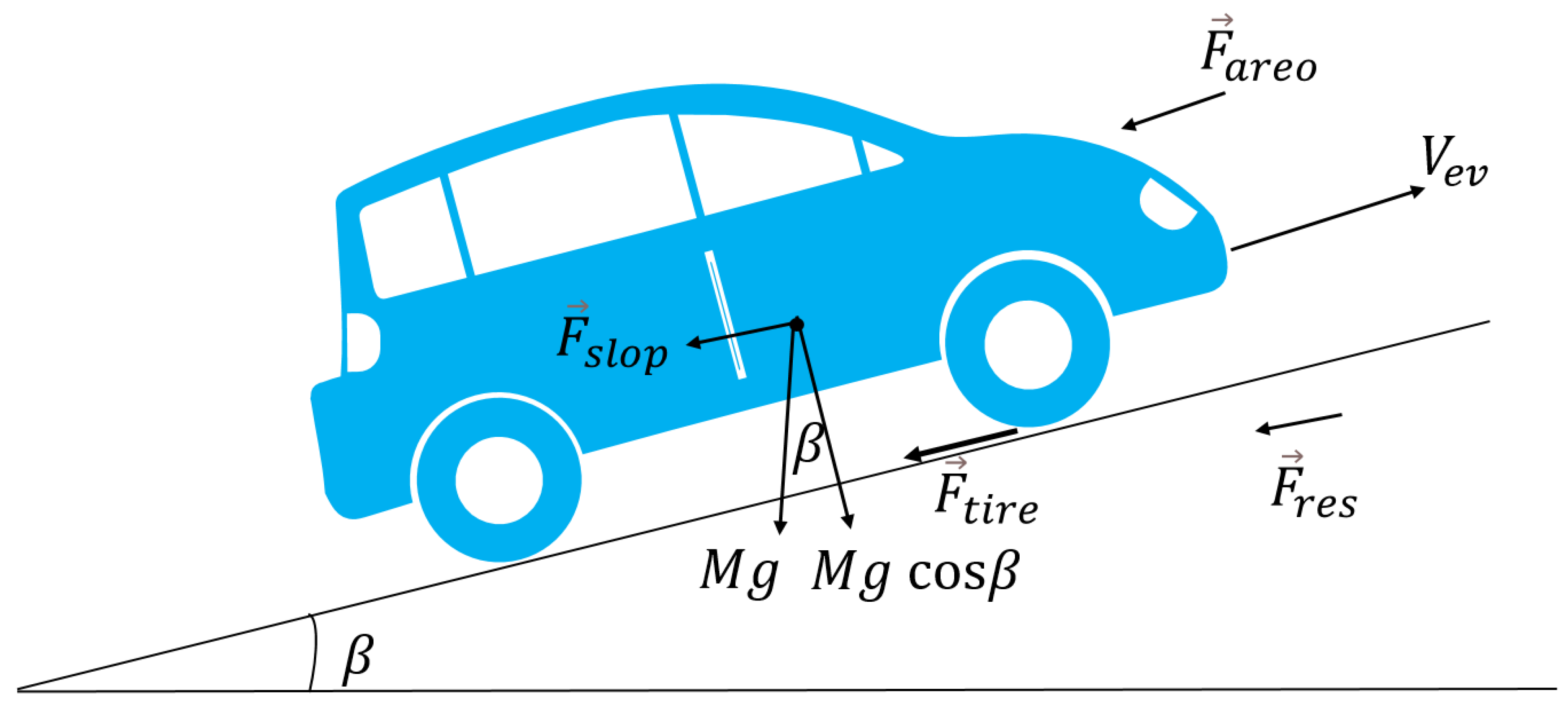
2.1.1. Dimensional Study of an Electric Vehicle
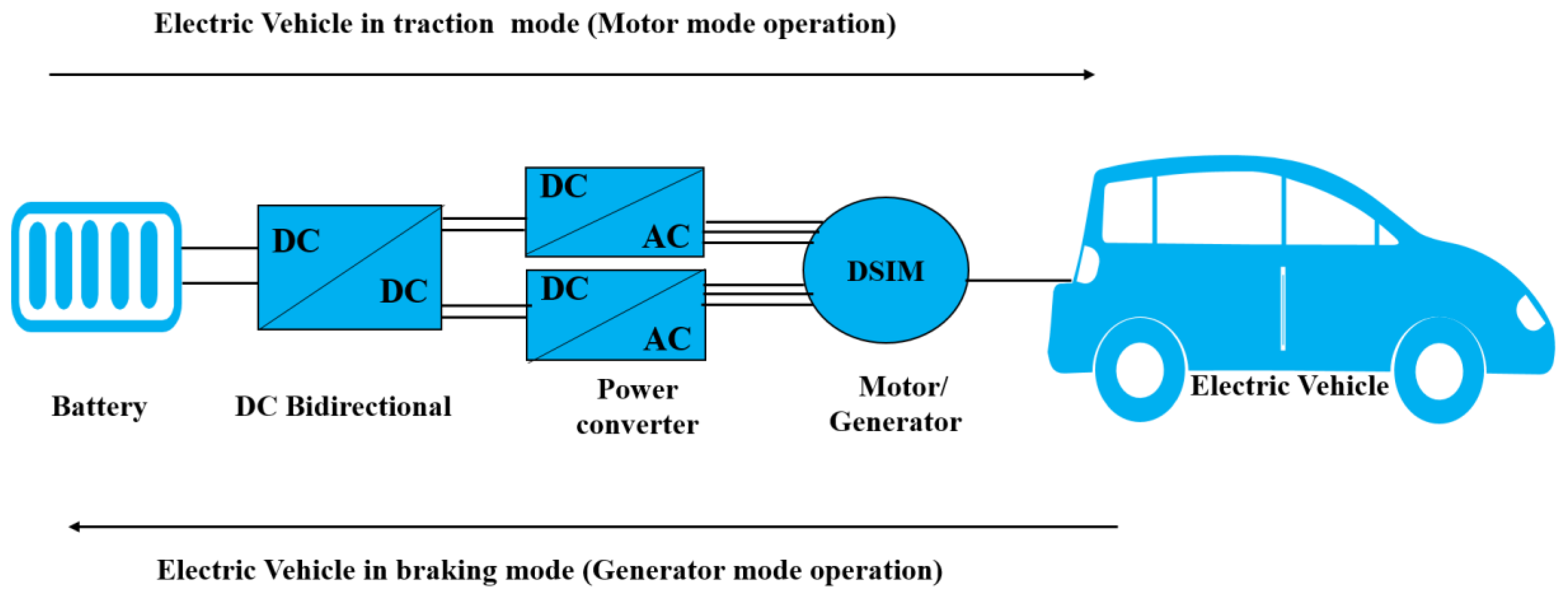
2.1.2. Traction Chain
Energy Source of an Electric Vehicle
- High specific energy density: Lithium-ion batteries have a high specific energy density, meaning they can store a significant amount of energy in a relatively small volume. This enables a higher range for the electric vehicle without significantly increasing its weight.
- High specific power: Lithium-ion batteries can provide high power output, which is crucial for rapid acceleration and meeting the power demands of the electric motor.
- High charge and discharge efficiency: Lithium-ion batteries exhibit high efficiency in both charging and discharging, allowing for rapid charging and efficient energy delivery to the vehicle’s motor.
- Long lifespan: Compared to other battery types, lithium-ion batteries have a longer lifespan, reducing replacement costs and enhancing the overall durability of the energy storage system in the electric vehicle.
- Low self-discharge rate: Lithium-ion batteries have a relatively low self-discharge rate, meaning they can retain their charge for extended periods without requiring frequent recharging. This is advantageous for electric vehicles that may remain unused for prolonged periods.
- Established technology: Lithium-ion batteries are widely used across various industries, resulting in well-developed manufacturing and recycling infrastructure, as well as extensive knowledge regarding their usage and maintenance.
Static Converters of an Electric Vehicle
- DC/DC Bidirectional converter is used for energy management and energy conversion in both directions, traction and braking.
- DC/AC converter is used to transform the energy stored in the battery into electrical energy suitable for operating the vehicle’s electric motor during towing and to provide real-time control of motor speed and torque, enabling precise power management and optimized efficiency.
- AC/DC converter is used to transfer the motor’s kinetic energy into electrical energy stored in the battery during braking and to control the battery’s charging voltage and current, essential for efficient and safe battery recharging.
Motorization of an Electric Vehicle
- DSIMs offer high energy efficiency, contributing to a greater electric vehicle range.
- DSIMs provide high power and torque, essential for optimal performance in terms of acceleration and load capacity.
- DSIMs are known for their reliability and longevity, reducing the risk of breakdowns and maintenance costs.
- DSIMs have a relatively simple design compared to other types of electric machines, which facilitates their integration into vehicle propulsion systems.
- DSIMs offer precise control of speed and torque, allowing them to effectively adapt to variations in load and speed encountered during driving.
- a.
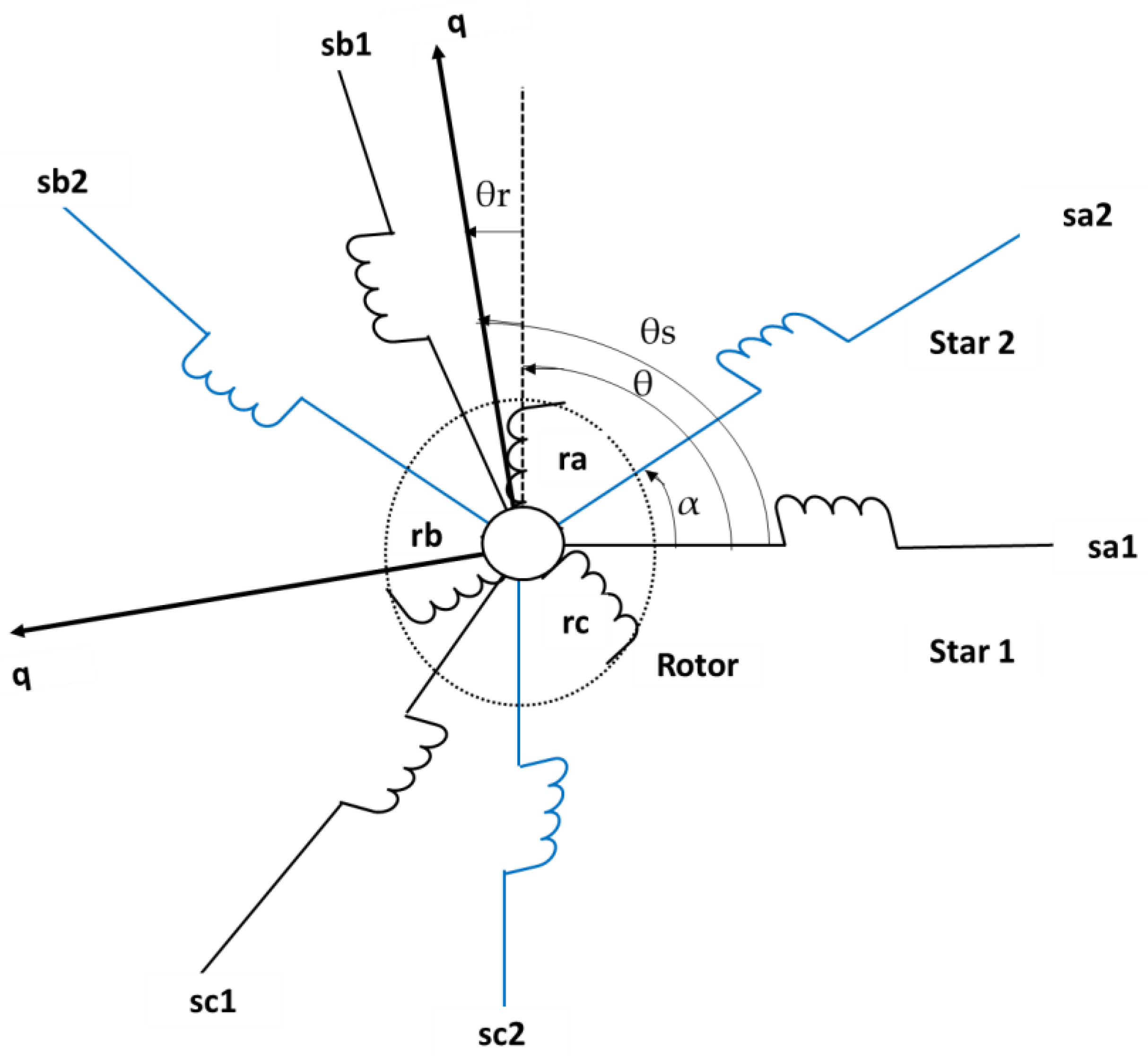
- Representation of the machine
- b.
- Machine Modeling
- Stator windings: The DSIM stator is divided into two sets of windings, often referred to as “star 1” and “star 2”. Each set comprises three phases, giving a total of six stator phases.
- Rotor windings: The DSIM rotor also comprises three phases. These rotor windings interact with the stator’s magnetic field and contribute to the machine’s operation.
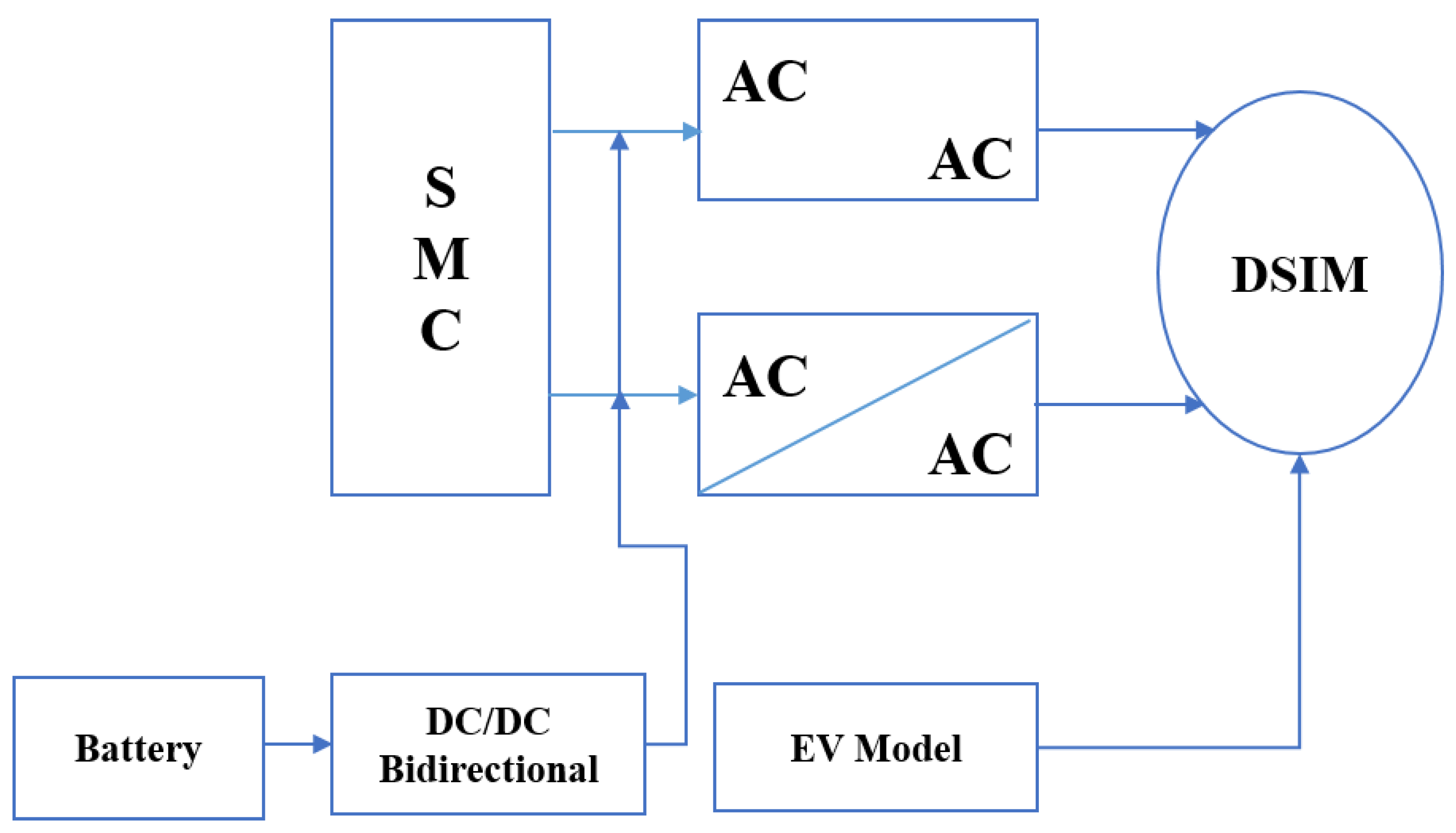
2.2. Control of the Electric Vehicle
- Precision: It enables precise control of the system, ensuring optimal performance of the electric vehicle in terms of acceleration, deceleration, and speed maintenance.
- Stability: It ensures robust stability, even in the presence of external disturbances or parameter uncertainties, ensuring stable operation of the vehicle in various driving conditions.
- Simplicity: It is straightforward to implement and adjust, facilitating its integration into the electric vehicle’s control system.
- Responsiveness: It provides quick responses to changes in driving conditions, allowing for dynamic and effective adaptation to user commands.
- Robustness: It is renowned for its robustness against variations in system parameters and external disturbances, ensuring reliable control of the electric vehicle even in challenging environments.
2.2.1. Control Principle
2.2.2. Control Equations
3. Results and Discussion
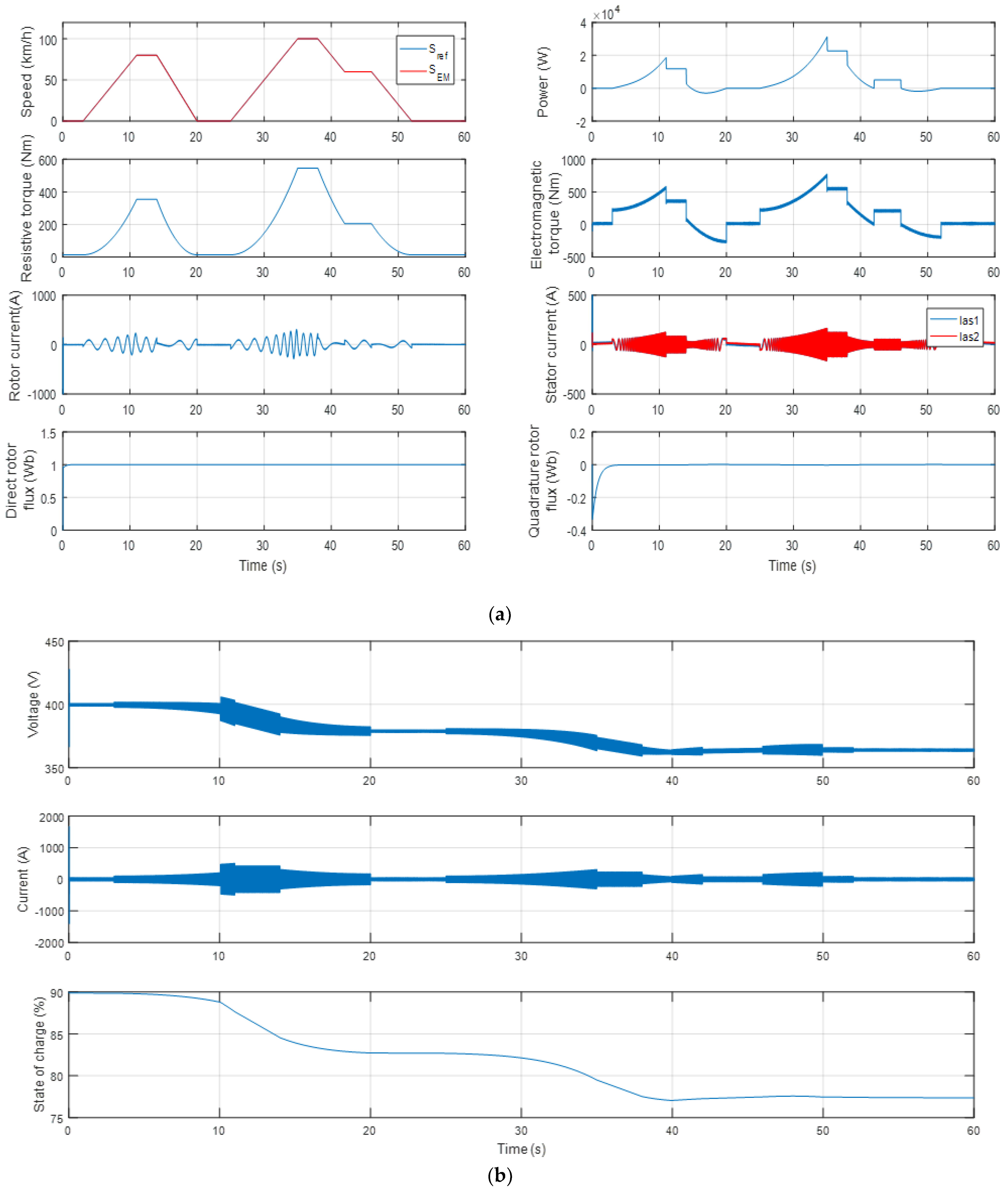
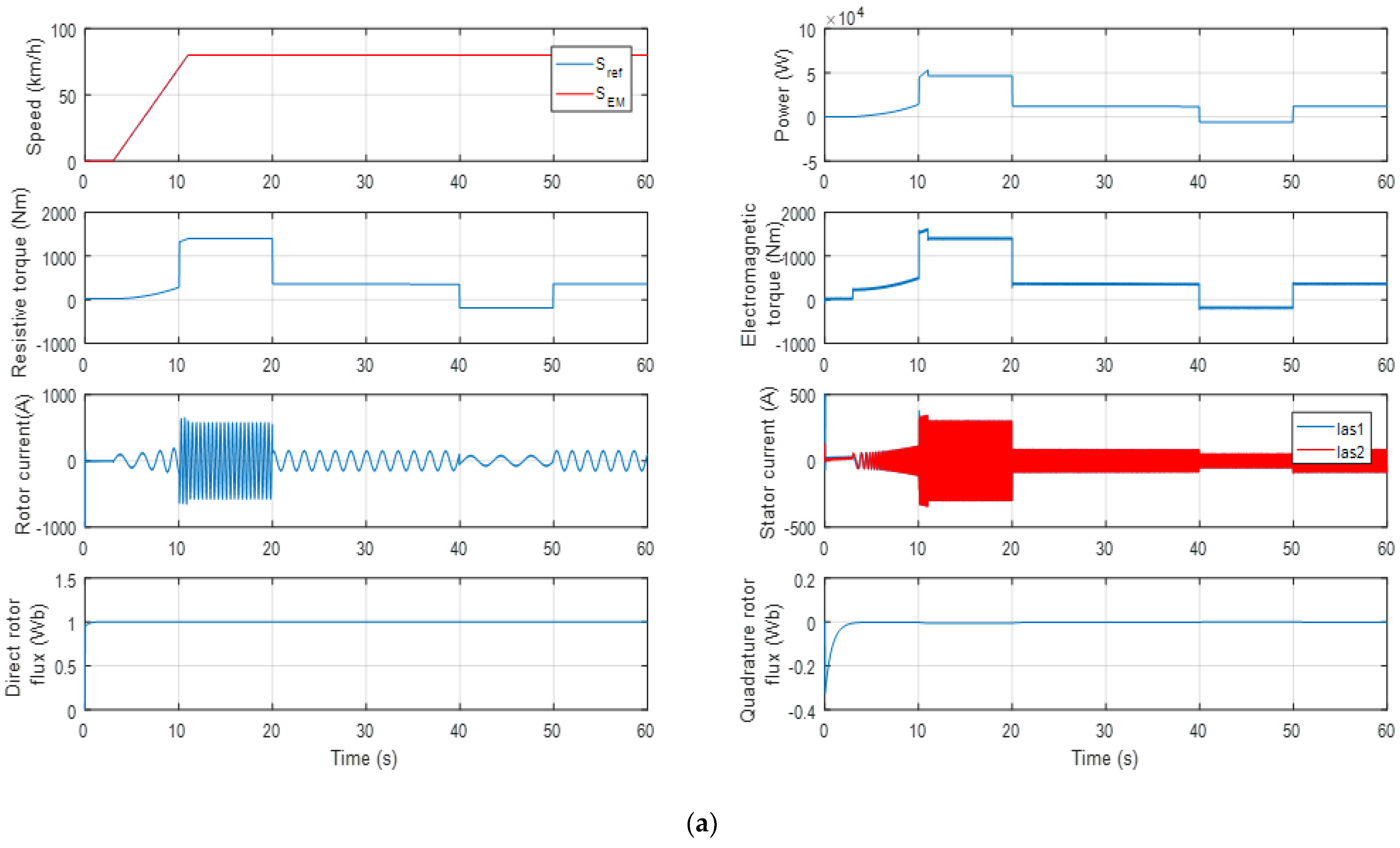
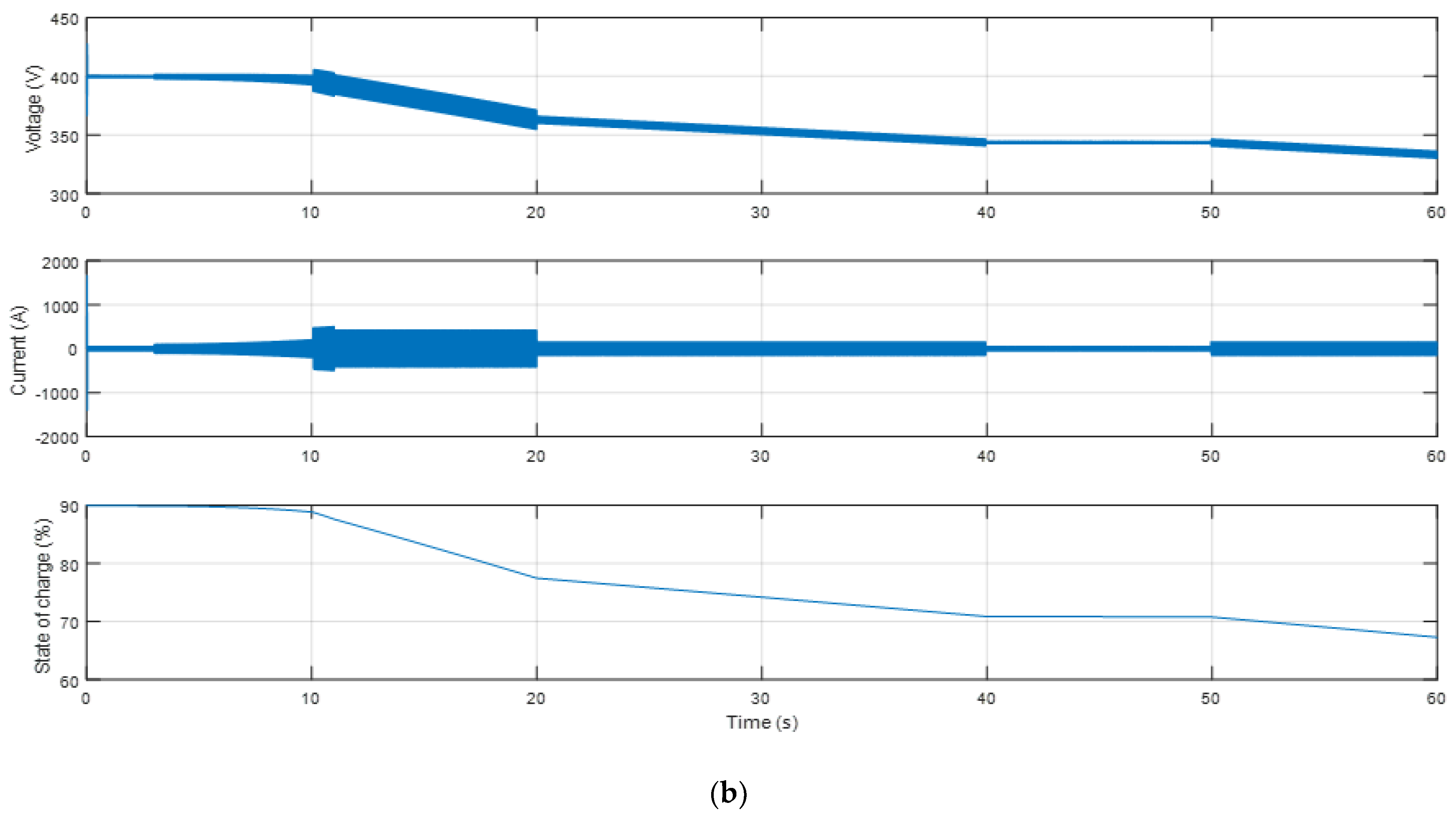
3.1. Simulation Results of Test 1: Speed Variation
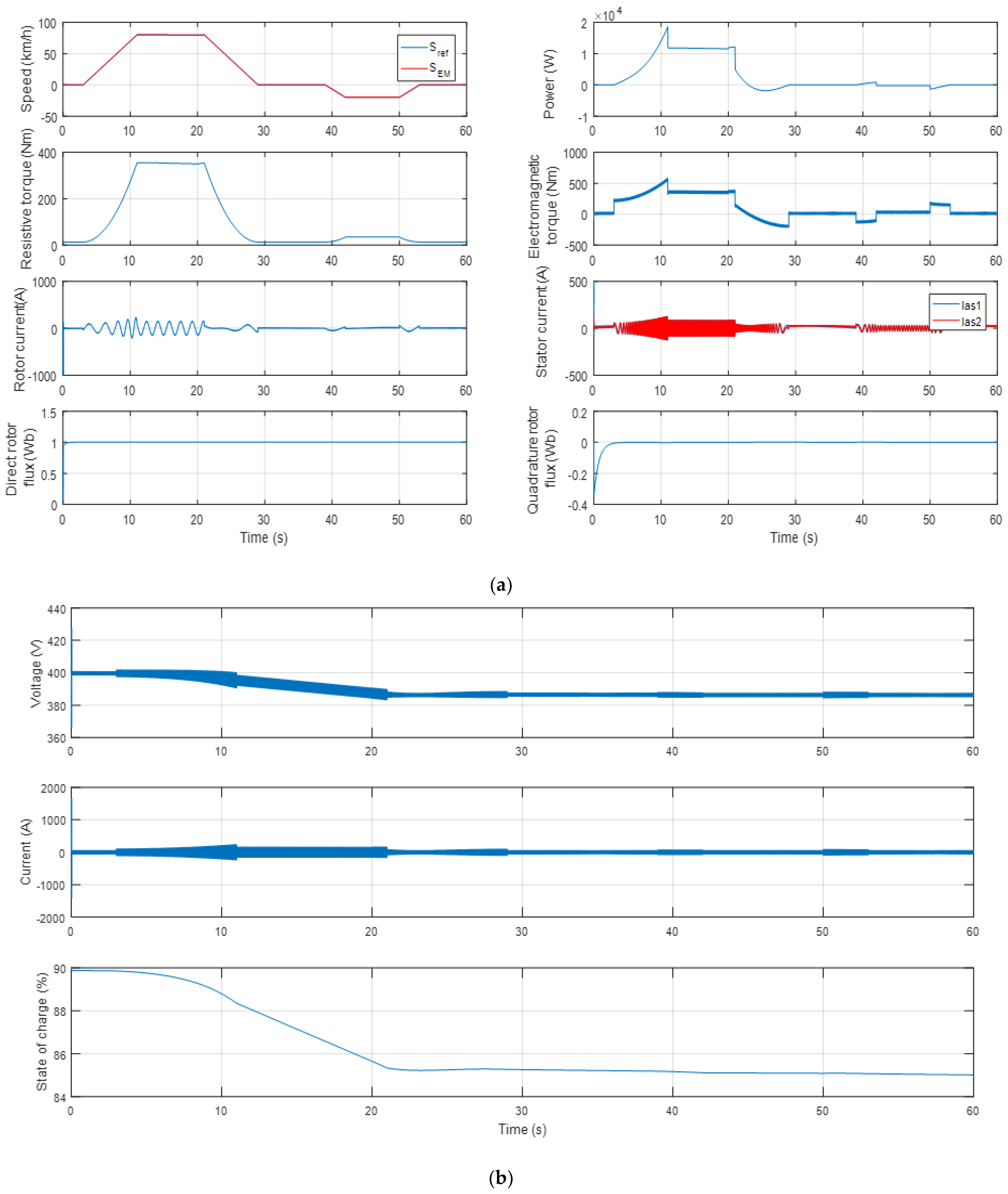
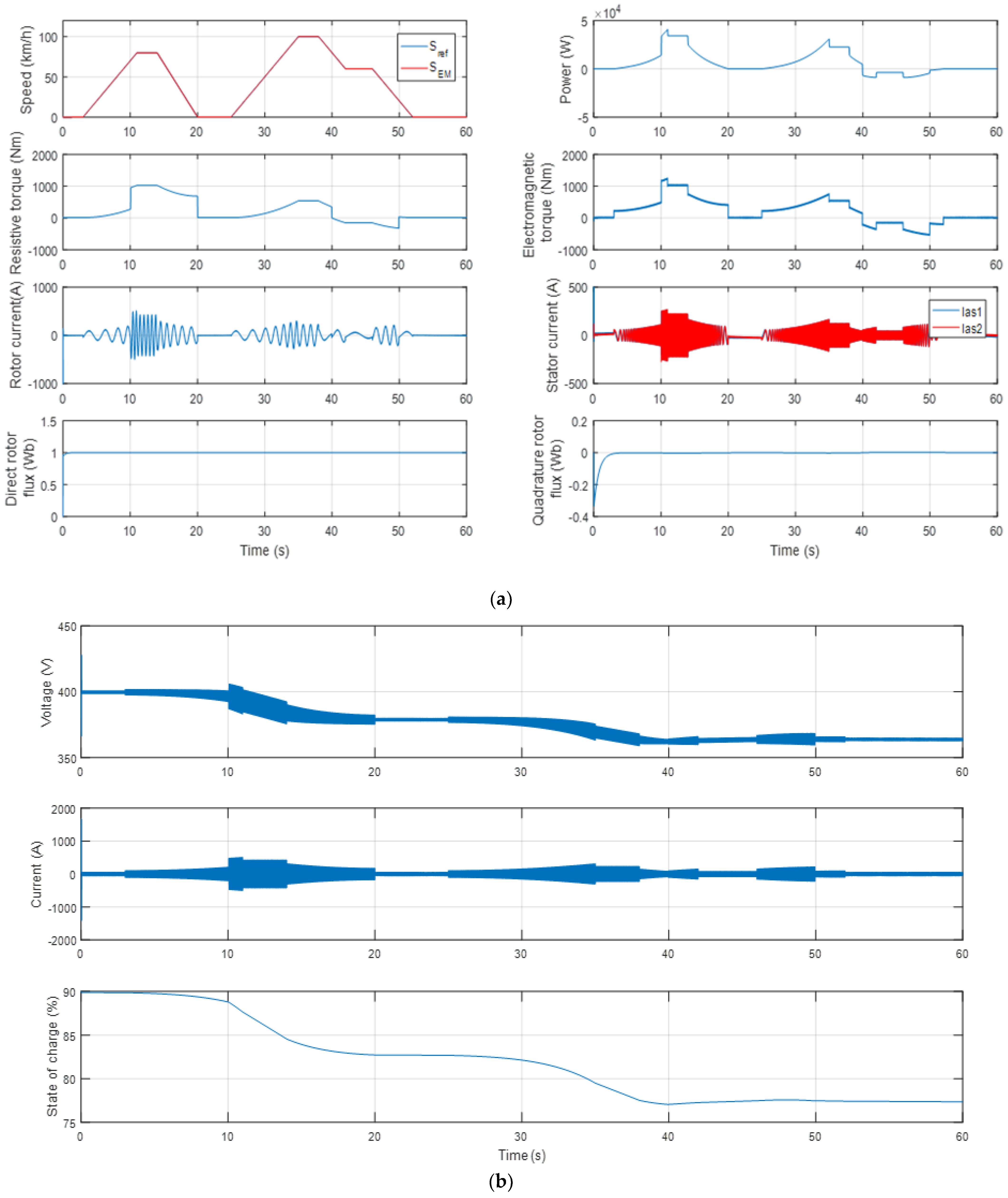
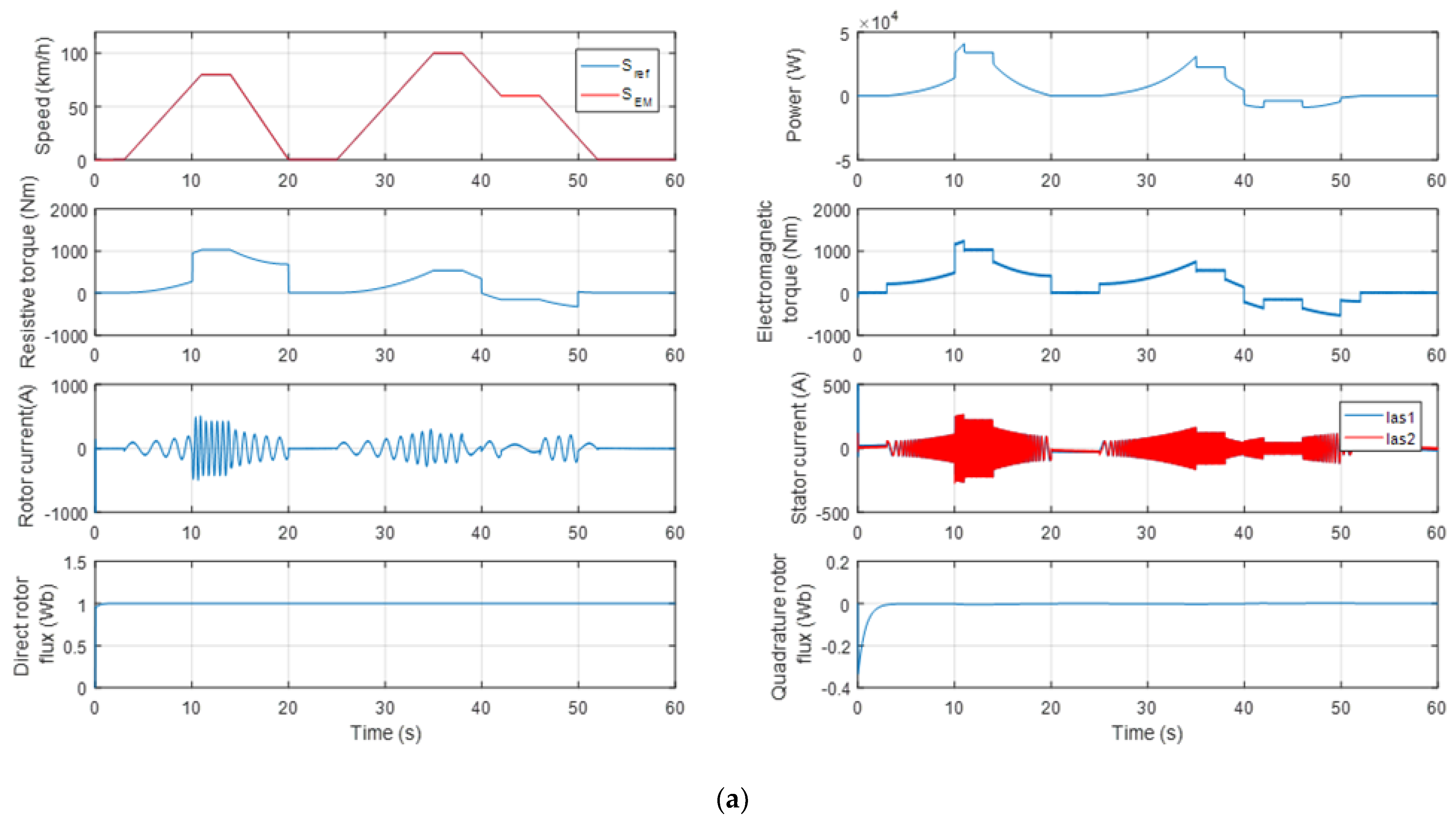
3.2. Simulation Results of Test 2: Speed Reversal
- Forward speed: starts with a stop phase of 3 s, followed by an acceleration phase to 80 km/h of 8 s after a stabilized phase lasting 10 s, and deceleration to 0 km/h of 8 s with a stop phase of 10 s.
- Reverse speed: starts with the last stop phase followed by an acceleration phase to 20 km/h of 3 s after a stabilized phase lasting 8 s, and deceleration to 0 km/h of 3 s with a stop phase from the second 53.
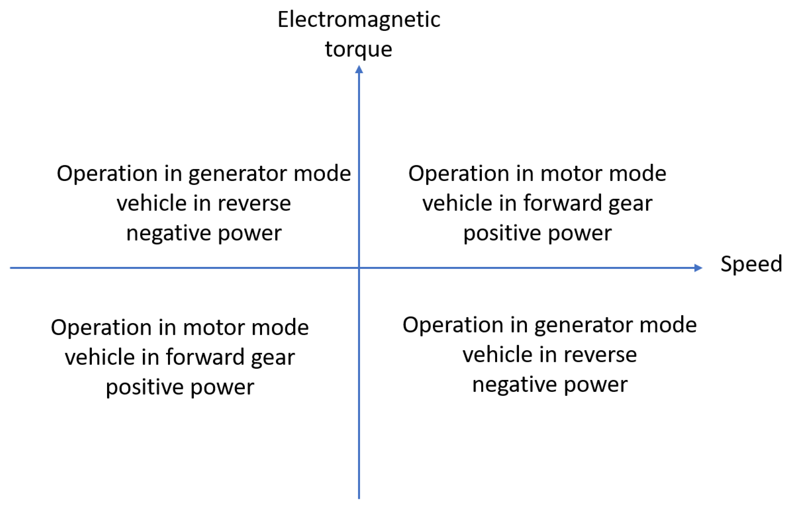
- The first quadrant represents system operation in a motor mode in the forward direction. Power is positive (Ωm > 0 Cem > 0), which means the system is consuming energy. Energy is transferred from the sources to the motor.
- The second quadrant corresponds to operation in a generator or braking mode in the forward direction. Power is negative (Ωm > 0 Cem < 0), which means the system is producing energy. Energy is transferred from the motor to the sources.
- The third quadrant represents system operation in a motor mode in reverse. Power is positive (Ωm < 0 Cem < 0), indicating energy consumption.
- Energy is again transferred from the sources to the motor.
- The fourth quadrant corresponds to operation in generator mode or braking in reverse. Power is negative (Ωm < 0 Cem > 0), meaning that the system is generating energy. Energy is transferred from the motor to the sources.
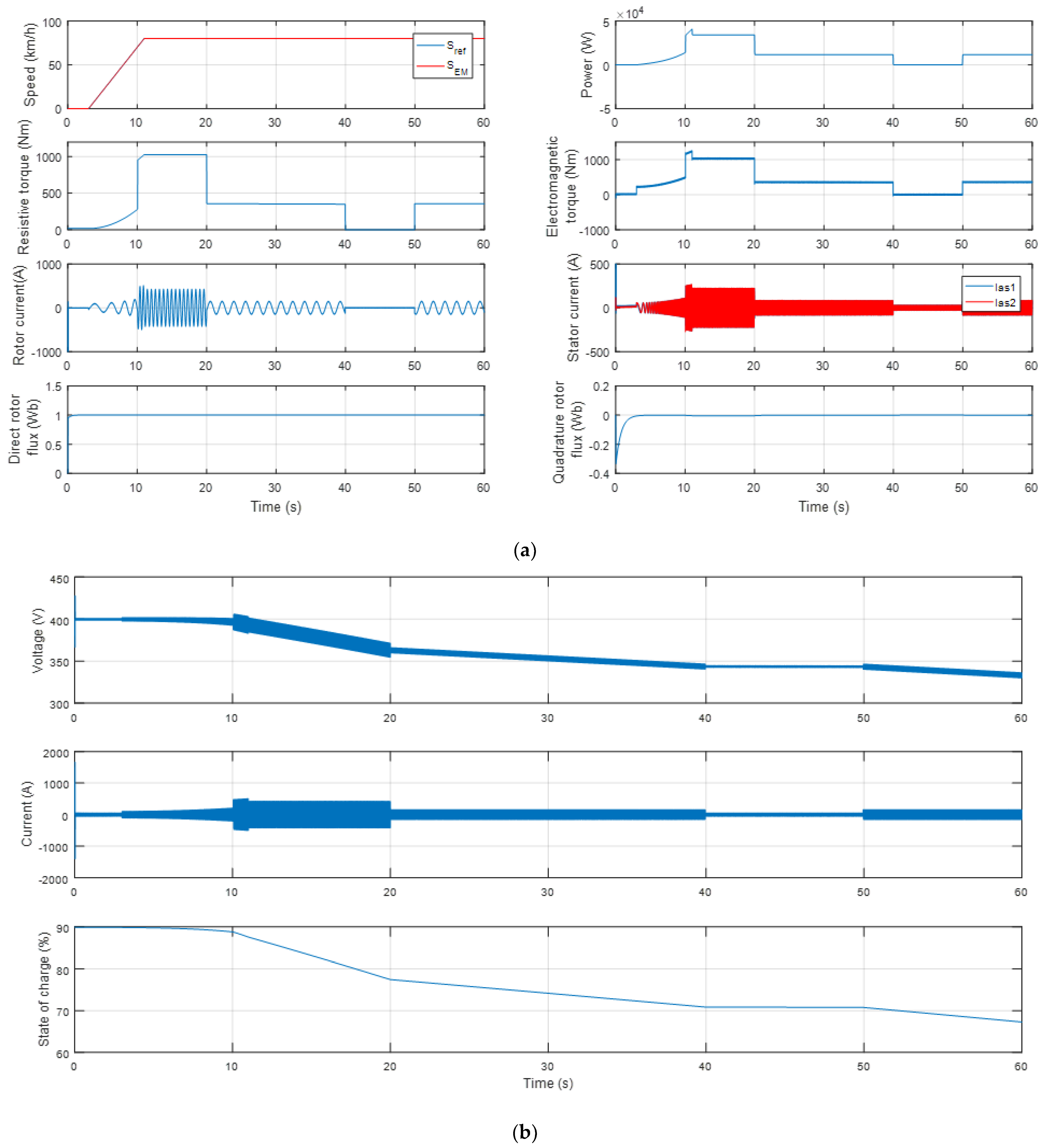
3.3. Simulation Results of Test 3: Slope Variation
- From 10 s to 20 s, while the vehicle is climbing 30%, the EV requires a very high level of energy, so it can triple the energy consumed during traction on a straight road.
- From 40 s to 50 s, when the vehicle is decelerating by 15%, the EV supplies minimal energy during traction and about the gradient.
3.4. Simulation Results of Test 4: Load Increase
3.5. Simulation Results of Test 5: Speed Variation and Slope Variation
3.6. Simulation Results of Test 6: Robustness Test
4. Conclusions
Author Contributions
Funding
Data Availability Statement
Acknowledgments
Conflicts of Interest
Abbreviations
| EV | Electric vehicle |
| DSIM | Dual-star induction machine |
| p | Number of pole pairs |
| J | Total inertia of rotating parts |
| F | Network Frequency in ‘Hz’ |
| m | The total mass of the vehicle in ‘kg’ |
| g | The gravity in ‘m/s2’ |
| β | The slope angle in ‘rad/s’ |
| α | The electrical angle in ‘rad/s’ |
| pair | The density of the air in ‘kg/m2’ |
| The frontal area of the vehicle in ‘m2’ | |
| Wheel radius ‘m’ | |
| The total resistive force in ‘N’ | |
| The resistant couple in ‘Nm’ | |
| The power of the electric vehicle in ‘w’ | |
| The speed of the vehicle in ‘m/s2’ | |
| Voltages of star 1 in Park reference frame “d, q” in ‘V’ | |
| Voltages of star 2 in Park reference frame “d, q” in ‘V’ | |
| Rotor voltages in Park reference frame “d, q “ in ‘V’ | |
| Star 1 currents in the Park reference frame “d, q” in ‘A’ | |
| Star 2 currents in Park reference frame “d, q” in ‘A’ | |
| Rotor currents in Park reference frame “d, q” in ‘A’ | |
| Flux of star 1 in Park reference frame “d, q” in ‘wb’ | |
| Flux of star 2 in Park reference frame “d, q” in ‘wb’ | |
| Rotor fluxes in the Park reference frame “d, q” in ‘wb’ | |
| Stator resistances of the star 1 in ‘Ω’ | |
| Stator resistances of the star 2 in ‘Ω’ | |
| Rotor resistances in ‘Ω’ | |
| Cyclic mutual inductance between star 1 and star 2 in ‘H’ | |
| Rotor inductance in ‘H’ | |
| LS | Stator inductance in ‘H’ |
| Armature Current in ‘A’ | |
| Flux imposed by the excitation current in ‘wb’ | |
| The aerodynamic drag coefficient | |
| The constant of the resistance force due to the displacement | |
| G | Speed reducer |
| Sliding coefficient | |
| K | Stator-rotor magnetic coupling coefficient |
| Proportional and integral gain of the speed controller. |
References
- Dalal, A.; Kumar, P. Design, Prototyping, and Testing of a Dual-Rotor Motor for Electric Vehicle Application. IEEE Trans. Ind. Electron. 2018, 65, 7185–7192. [Google Scholar] [CrossRef]
- Sanguesa, J.A.; Torres-Sanz, V.; Garrido, P.; Martinez, F.J.; Marquez-Barja, J.M. A Review on Electric Vehicles: Technologies and Challenges. Smart Cities 2021, 4, 372–404. [Google Scholar] [CrossRef]
- Yuvaraj, T.; Devabalaji, K.R.; Kumar, J.A.; Thanikanti, S.B.; Nwulu, N.I. A Comprehensive Review and Analysis of the Allocation of Electric Vehicle Charging Stations in Distribution Networks. IEEE Access 2024, 12, 5404–5461. [Google Scholar] [CrossRef]
- Gao, W.; Peng, C.; Bao, W.; Wu, C. Communication energy optimization of electric vehicle platoon on curved road. EURASIP J. Adv. Signal Process. 2021, 2021, 105. [Google Scholar] [CrossRef]
- Hussain, S.; Ahmed, M.A.; Kim, Y.-C. Efficient Power Management Algorithm Based on Fuzzy Logic Inference for Electric Vehicles Parking Lot. IEEE Access 2019, 7, 65467–65485. [Google Scholar] [CrossRef]
- Fu, Z.; Zhu, L.; Tao, F.; Si, P.; Sun, L. Optimization based energy management strategy for fuel cell/battery/ultracapacitor hybrid vehicle considering fuel economy and fuel cell lifespan. Int. J. Hydrogen Energy 2020, 45, 8875–8886. [Google Scholar] [CrossRef]
- Rimpas, D.; Kaminaris, S.D.; Aldarraji, I.; Piromalis, D.; Vokas, G.; Papageorgas, P.G.; Tsaramirsis, G. Energy management and storage systems on electric vehicles: A comprehensive review. Mater. Today Proc. 2022, 61, 813–819. [Google Scholar] [CrossRef]
- Karmaker, A.K.; Hossain, M.A.; Pota, H.R.; Onen, A.; Jung, J. Energy Management System for Hybrid Renewable Energy-Based Electric Vehicle Charging Station. IEEE Access 2023, 11, 27793–27805. [Google Scholar] [CrossRef]
- Vodovozov, V.; Raud, Z.; Petlenkov, E. Review on Braking Energy Management in Electric Vehicles. Energies 2021, 14, 4477. [Google Scholar] [CrossRef]
- Huang, H.; Tu, Q.; Jiang, C.; Pan, M.; Zhu, C. An Electronic Line-Shafting Control Strategy Based on Sliding Mode Observer for Distributed Driving Electric Vehicles. IEEE Access 2021, 9, 38221–38235. [Google Scholar] [CrossRef]
- Cao, W.; Bukhari, A.A.S.; Aarniovuori, L. Review of electrical motor drives for electric vehicle applications. Mehran Univ. Res. J. Eng. Technol. 2019, 38, 525–540. [Google Scholar] [CrossRef]
- Cisse, K.M.; Hlioui, S.; Belhadi, M.; Rollet, G.M.; Gabsi, M.; Cheng, Y. Design optimization of multi-layer permanent magnet synchronous machines for electric vehicle applications. Energies 2021, 14, 7116. [Google Scholar] [CrossRef]
- Hamitouche, K.; Chekkal, S.; Amimeur, H.; Aouzellag, D. A New Control Strategy of Dual Stator Induction Generator with Power Regulation. J. Eur. Syst. Autom. 2020, 53, 469–478. [Google Scholar] [CrossRef]
- Lallouani, H.; Ssaad, B. Performances of type 2 fuzzy logic control based on direct torque control for double star induction machine. Rev. Roum. Sci. Tech.-Ser. Electrotech. Energetique 2020, 65, 103–108. [Google Scholar]
- Liu, Y.; Liu, K.; Zhou, Y.; Chen, Y.; Wei, D.; Zhou, S.; Luan, H. Study on the Design and Speed Ratio Control Strategy of Continuously Variable Transmission for Electric Vehicle. IEEE Access 2023, 11, 107880–107891. [Google Scholar] [CrossRef]
- Hassan, M.R.M.; Mossa, M.A.; Dousoky, G.M. Evaluation of Electric Dynamic Performance of an Electric Vehicle System Using Different Control Techniques. Electronics 2021, 10, 2586. [Google Scholar] [CrossRef]
- Miao, Y.; Hynan, P.; von Jouanne, A.; Yokochi, A. Current Li-Ion Battery Technologies in Electric Vehicles and Opportunities for Advancements. Energies 2019, 12, 1074. [Google Scholar] [CrossRef]
- Wang, Y.; Liu, C.; Pan, R.; Chen, Z. Modeling and state-of-charge prediction of lithium-ion battery and ultracapacitor hybrids with a co-estimator. Energy 2017, 121, 739–750. [Google Scholar] [CrossRef]
- Timilsina, L.; Badr, P.R.; Hoang, P.H.; Ozkan, G.; Papari, B.; Edrington, C.S. Battery Degradation in Electric and Hybrid Electric Vehicles: A Survey Study. IEEE Access 2023, 11, 42431–42462. [Google Scholar] [CrossRef]
- Schwenk, K.; Meisenbacher, S.; Briegel, B.; Harr, T.; Hagenmeyer, V.; Mikut, R. Integrating Battery Aging in the Optimization for Bidirectional Charging of Electric Vehicles. IEEE Trans. Smart Grid 2021, 12, 5135–5145. [Google Scholar] [CrossRef]
- Sayed, K.; Almutairi, A.; Albagami, N.; Alrumayh, O.; Abo-Khalil, A.G.; Saleeb, H.A. Review of DC-AC Converters for Electric Vehicle Applications. Energies 2022, 15, 1241. [Google Scholar] [CrossRef]
- Islam, R.; Rafin, S.H.; Mohammed, O.A. Comprehensive Review of Power Electronic Converters in Electric Vehicle Applications. Forecasting 2020, 5, 22–80. [Google Scholar] [CrossRef]
- Jape, S.R.; Thosar, A. Comparison of electric motors for electric vehicle application. Int. J. Res. Eng. Technol. 2017, 6, 12–17. [Google Scholar] [CrossRef]
- Azib, A.; Ziane, D.; Rekioua, T.; Tounzi, A. Robustness of the direct torque control of double star induction motor in fault condition. Rom. J. Tech. Sci. Electr. Energy Eng. Ser. 2016, 61, 147–152. [Google Scholar]
- Tir, Z.; Soufi, Y.; Hashemnia, M.N.; Malik, O.P.; Marouani, K. Fuzzy logic field oriented control of double star induction motor drive. Electr. Eng. 2017, 99, 495–503. [Google Scholar] [CrossRef]
- Chaabane, H.; Eddine, K.D.; Salim, C. Indirect self tuning adaptive control of double star induction machine by sliding mode. Rev. Roum. Sci. Tech.-Ser. Electrotech. Energetique 2019, 64, 409–415. [Google Scholar]
- Ibrahim, N.; Abdelaziz, M.; Ghoneima, M.; Hammad, S. Implementation of vector control on electric vehicle traction system. Bull. Natl. Res. Cent. 2020, 44, 22. [Google Scholar] [CrossRef]
- Xiu, C.; Wang, R. Sliding Mode Control Based on Dynamic Model for Transport Vehicle. IEEE Access 2018, 6, 33819–33825. [Google Scholar] [CrossRef]
- Li, W.; Zhu, W.; Zhu, X.; Guo, J. Two-Time-Scale Braking Controller Design with Sliding Mode for Electric Vehicles over CAN. IEEE Access 2019, 7, 128086–128096. [Google Scholar] [CrossRef]
- Layadi, N.; Djerioui, A.; Zeghlache, S.; Mekki, H.; Houari, A.; Gong, J.; Berrabah, F. Fault-tolerant control based on sliding mode controller for double-star induction machine. Arab. J. Sci. Eng. 2020, 45, 1615–1627. [Google Scholar] [CrossRef]


| Parameters | Values |
|---|---|
| Mass of the vehicle | |
| Wheel radius | |
| Frontal area | |
| Resistance force constant | |
| The density of the air | |
| Aerodynamic drag coefficients | |
| Vehicle dimensions: | 4 m/1.8 m/1.6 m |
| Time (s) | [3, 11] | [11, 14] | [14, 20] | [20, 25] | [25, 35] |
| Speed (km/h) | 0–80 | 80 | 80–0 | 0 | 0–100 |
| Traction mode | Motor | Motor | Generator | Stop | Motor |
| Battery state | Discharging | Discharging | Charging | Stable | Discharging |
| Time (s) | [35, 38] | [38, 42] | [42, 46] | [46–52] | [52, 60] |
| Speed (km/h) | 100 | 100–60 | 60 | 60–0 | 0 |
| Traction mode | Motor | Generator | Motor | Generator | Stop |
| Battery state | Discharging | Charging | Discharging | Charging | Stable |
Disclaimer/Publisher’s Note: The statements, opinions and data contained in all publications are solely those of the individual author(s) and contributor(s) and not of MDPI and/or the editor(s). MDPI and/or the editor(s) disclaim responsibility for any injury to people or property resulting from any ideas, methods, instructions or products referred to in the content. |
© 2024 by the authors. Licensee MDPI, Basel, Switzerland. This article is an open access article distributed under the terms and conditions of the Creative Commons Attribution (CC BY) license (https://creativecommons.org/licenses/by/4.0/).
Share and Cite
Benbouya, B.; Cheghib, H.; Chrenko, D.; Delgado, M.T.; Hamoudi, Y.; Rodriguez, J.; Abdelrahem, M. Sliding Mode Control of an Electric Vehicle Driven by a New Powertrain Technology Based on a Dual-Star Induction Machine. World Electr. Veh. J. 2024, 15, 155. https://doi.org/10.3390/wevj15040155
Benbouya B, Cheghib H, Chrenko D, Delgado MT, Hamoudi Y, Rodriguez J, Abdelrahem M. Sliding Mode Control of an Electric Vehicle Driven by a New Powertrain Technology Based on a Dual-Star Induction Machine. World Electric Vehicle Journal. 2024; 15(4):155. https://doi.org/10.3390/wevj15040155
Chicago/Turabian StyleBenbouya, Basma, Hocine Cheghib, Daniela Chrenko, Maria Teresa Delgado, Yanis Hamoudi, Jose Rodriguez, and Mohamed Abdelrahem. 2024. "Sliding Mode Control of an Electric Vehicle Driven by a New Powertrain Technology Based on a Dual-Star Induction Machine" World Electric Vehicle Journal 15, no. 4: 155. https://doi.org/10.3390/wevj15040155
APA StyleBenbouya, B., Cheghib, H., Chrenko, D., Delgado, M. T., Hamoudi, Y., Rodriguez, J., & Abdelrahem, M. (2024). Sliding Mode Control of an Electric Vehicle Driven by a New Powertrain Technology Based on a Dual-Star Induction Machine. World Electric Vehicle Journal, 15(4), 155. https://doi.org/10.3390/wevj15040155