Abstract
This research proposes a strategy to diagnose open-phase faults (OPF) and open-switching faults (OSF) in dual three-phase permanent magnet synchronous motor (DTP-PMSM) inverters. The method is based on the dual d–q predictive current model and involves establishing a mathematical model and utilizing the finite control set model predictive current extraction technique to predict the motor current. It then analyzes the characteristics of the switching-tube current under both normal and fault conditions. Finally, a fault predictive current model is introduced and the residual is calculated based on the predicted fault current value and the actual measured current value to diagnose the inverter fault. The proposed method effectively overcomes misjudgment issues encountered in traditional open-circuit fault diagnosis of inverters. It enhances the system’s response speed during dynamic processes and strengthens the robustness of diagnosis algorithm parameters. The experimental results demonstrate that the proposed method can rapidly, effectively, and accurately diagnose open-circuit faults presented in this paper fastest within one-fifth of a current cycle. It achieves a diagnostic accuracy rate of 97% in the dual three-phase permanent magnet synchronous motor drive system.
1. Introduction
The development of AC transmission has led to increasing research on high-power control systems. One area of interest for scholars is multiphase motors, which are characterized by low voltage, high power, small torque ripple, and strong fault tolerance [1,2,3]. Dual three-phase permanent magnet synchronous motors have been extensively studied among multiphase motors. These motors have several advantages over ordinary three-phase motors, including reduced torque ripple and improved fault tolerance. As a result, dual three-phase permanent magnet synchronous motors are an excellent choice for applications requiring high power and high reliability, meeting the demanding performance requirements of the current engineering field [4,5].
The power switching devices in motor drive systems play a crucial role, but they often experience frequent switching states over long periods o, leading to switching losses and heat build-up. In addition, these devices are susceptible to environmental factors, transient conditions during operation, and overload situations that increase the risk of failure. Short-circuit faults are particularly serious as they can quickly propagate throughout the system [6]. Currently, hardware circuits such as fast fuses are used to protect power-switching devices from short-circuit faults by converting them to open-circuit faults once they occur. This helps to prevent further damage to the system. However, unlike short-circuit faults, which immediately stop the operation of the system, open-circuit faults do not necessarily lead to an immediate shutdown but can affect the performance of the motor. If open-circuit faults are not recognized and rectified immediately, they can lead to secondary faults in the system and cause major damage [7]. Therefore, the effective diagnosis of open-circuit faults in inverter switchgear is of great importance to ensure the reliability and safety of the system.
The core of fault detection and localization technology lies in extracting key signal features and comparing them with benchmark parameters to evaluate deviations during equipment operation [8], providing data support for fault diagnosis and localization. Open-circuit faults can significantly affect the system’s output current and voltage in inverter applications. Current signals, as essential monitoring indicators in motor control systems, are often selected for open-circuit fault diagnosis using methods such as phase current average value [9], radius [10], angle [11], Park vector [12], zero crossing (ZC) feature [13,14], and similarity feature [15].
To simplify fault detection, a method based on the unique x–y plane current of multiphase motors was proposed in reference [16]. This method utilizes VSD to detect open-phase faults in six-phase induction motors. Similarly, reference [17] proposes a fault diagnosis method for a single switch open-circuit fault in a six-phase fault-tolerant permanent magnet synchronous motor system. This method is based on the average current Park’s vector and compares the modulus of the average current Park’s vector before and after the switch fault in two orthogonal subspaces to determine whether a switch fault has occurred. On the other hand, voltage-based open-circuit fault diagnosis methods typically require additional voltage sensors in the system. These methods diagnose faults by measuring the phase voltage, line voltage, or voltage values at key points output by the inverter, as discussed in references [18,19,20,21,22]. After considering factors such as neutral point voltage imbalance and time-offset injection, references [23] proposed an assumption-based method for T-type three-level inverter OC fault diagnosis based on the output phase voltage model. The method established a phase voltage model and determined the fault location based on the amplitude and angle of the residual vector. The proposed method in [24] presents a technique for rapid open-circuit fault diagnosis on an induction motor drive system by calculating the common-mode voltage, enabling diagnosis within five control cycles. However, this approach necessitates the design of a complex observer to estimate the motor back-EMF.
In summary, due to their similar characteristics, previous fault diagnosis methods have faced difficulties in achieving simultaneous rapid detection of OPF and OSF. Therefore, this article proposes an online fault diagnosis scheme based on dual dq current prediction by combining model-based and signal-based diagnosis. The proposed strategy can be divided into three steps: first, detecting differences between normal and faulty models of permanent magnet synchronous motors to determine when faults occur; secondly, using different OPF models to predict general deviations between current and dq axis feedback currents for identifying faulty phases; finally, utilizing harmonic currents’ trajectory angles for specific fault diagnosis and localization. By employing this method, quick diagnoses of OSF and OPF in PMSM drivers can be achieved within one-fifth of a current cycle.
First, the topological structure and the basic principle of the DTP-PMSM are presented and a mathematical model of the DTP-PMSM is derived. Subsequently, the characteristics of the current at open fault are analyzed and the basic principle and methodology of the fault current model are explained in more detail. Furthermore, the use of the fault current model for the diagnosis of open faults in PMSMs is presented. Finally, the effectiveness of the proposed methodology is validated by experiments, and its feasibility in practice is discussed.
2. Mathematical Model of Dual Three-Phase PMSM
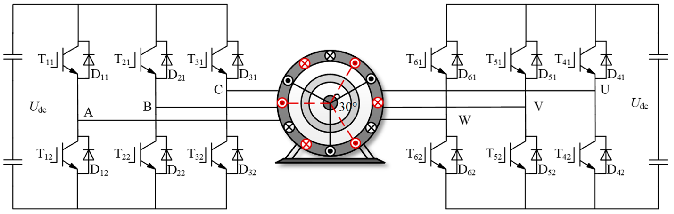
The main circuit topology of the dual three-phase PMSM driving system is shown in Figure 1. The stator consists of two groups of three-phase, symmetrical windings that are connected in a Y-shape. The two groups of windings are spatially separated by an electrical angle of 30° and are fed by a six-phase voltage source inverter. To simplify research and analysis, it is assumed that the back EMF of the motor is sinusoidally distributed.
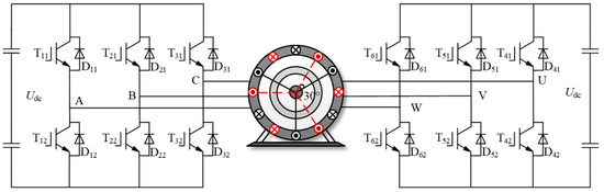
Figure 1.
Dual three-phase PMSM drive system diagram.
The expression for the stator voltage of a dual three-phase PMSM is
The U6s, I6s, ψ6s, and R6s, respectively, denote the stator voltage vector, phase current vector, magnetic flux vector, and stator resistance.
The vector space decoupling of the dual three-phase PMSM model in the d–q, x–y, o1–o2 coordinate systems for the continuous-time-domain voltage state equation
In the equation, Ld and Lq represent the dq-axis inductances, respectively; LZ denotes the stator side leakage inductance; id and iq are the dq-axis stator currents; ix and iy are the current components in the harmonic plane; io1 and io2 are the zero-sequence sub-plane currents; Rs is the stator resistance; ω is the angular frequency, and ψf is the magnitude of the magnetic flux linkage.
The widely used forward Euler method is chosen to discretize the current in Equation (2), as the influence of zero sequence subspace can be neglected due to center point isolation. The predicted values of current in each subspace are obtained accordingly.
3. Fault Analysis
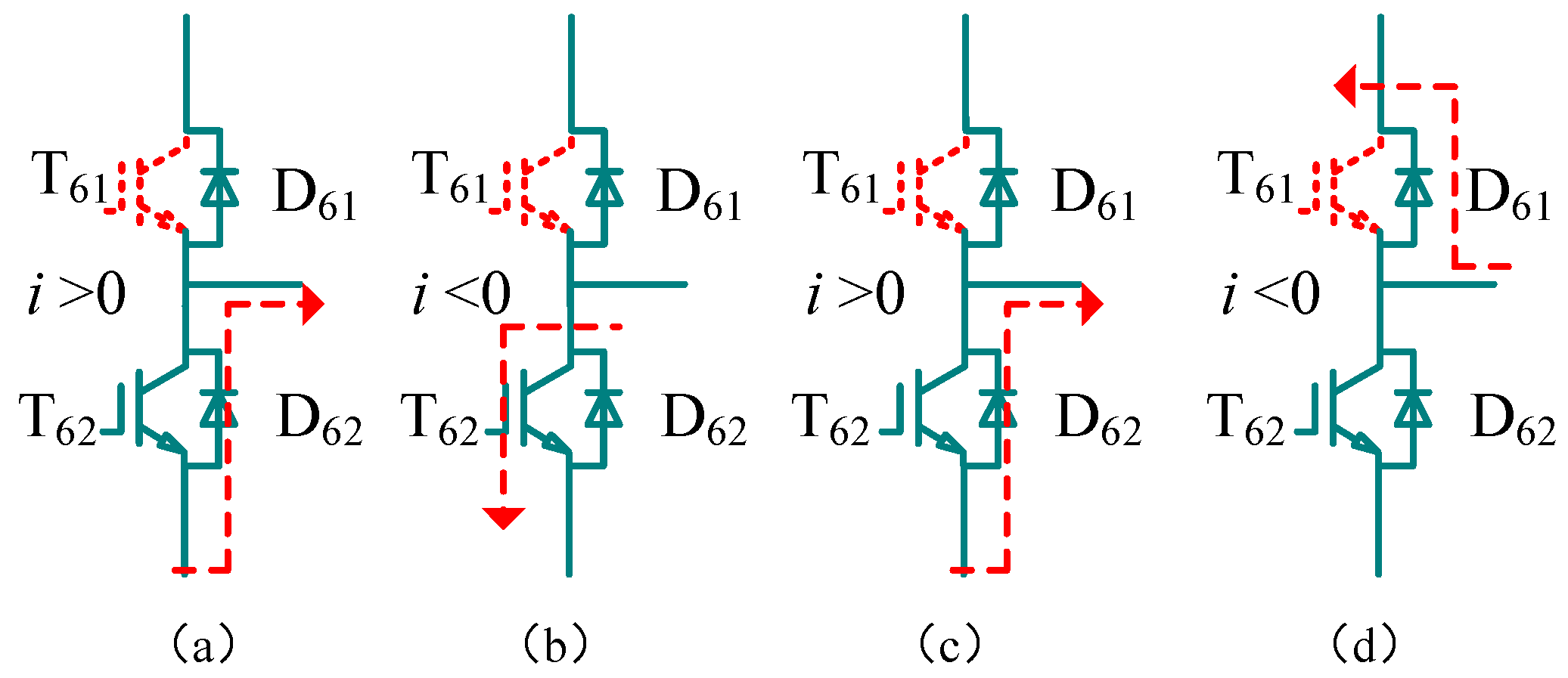
Figure 2 illustrates the voltage and current distortion caused by inverter bridge arm faults, using the W-phase current as an example.
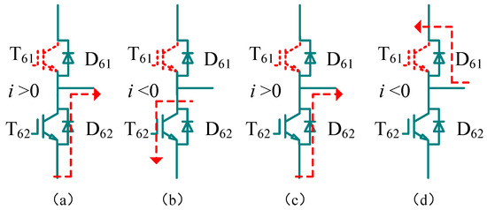
Figure 2.
Current paths under different switch states and current directions (The red arrow shows the current flow direction): (a) iW > 0, T61 = 0, and T62 = 1; (b) iW < 0, T61 = 0, and T62 = 1; (c) iW > 0, T61 = 1, and T62 = 0; and (d) iW < 0, T61 = 1, and T62 = 0.
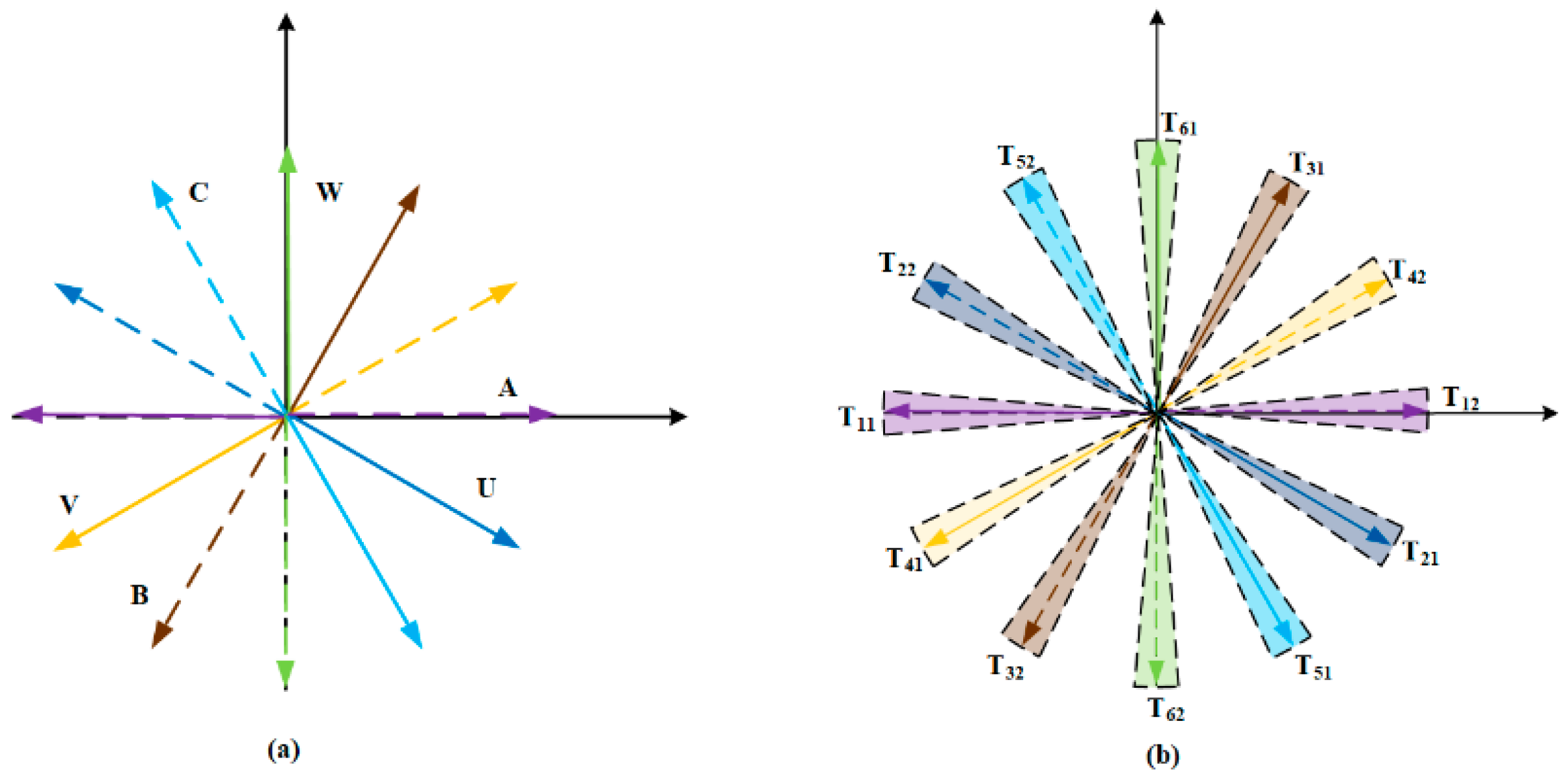
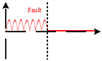
Following the T61 switch fault, the positive W-phase current is forced to zero within several switching cycles, as shown in Figure 2. The duration of these few cycles is negligible when compared to a full period. Consequently, the T61–OSF fault exhibits similar fault characteristics to the W-phase OPF in the positive half cycle, and the PMSM model with W-phase OPF applies to the T61–OSF. During the negative half-cycle of the W-phase current, it does not pass through T61; hence, the T61–OSF does not affect the W-phase current in the negative half-cycle. Analysis results can be obtained when an open-circuit fault occurs at T61. In addition, as shown in Figure 3, the trajectory of harmonic current can be observed in the case of OPF and OSF.
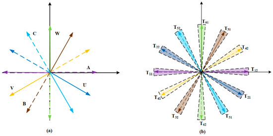
Figure 3.
x–y plane current trajectories: (a) different open-circuit faults; (b) different switching tube of an inverter.
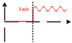
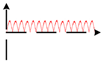
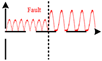
Similarly, this method can be applied to analyze various open-circuit fault scenarios. Figure 4. illustrates the fault phase currents for three types of faults: a single inverter open circuit, a single-phase open circuit, and a two-phase open circuit, when the drive system experiences a failure.
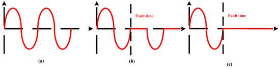
Figure 4.
Current waveform under the same conditions. (a) Health; (b) single pipe open circuit; (c) single-phase open circuit.
4. Proposed Fault Diagnosis Method
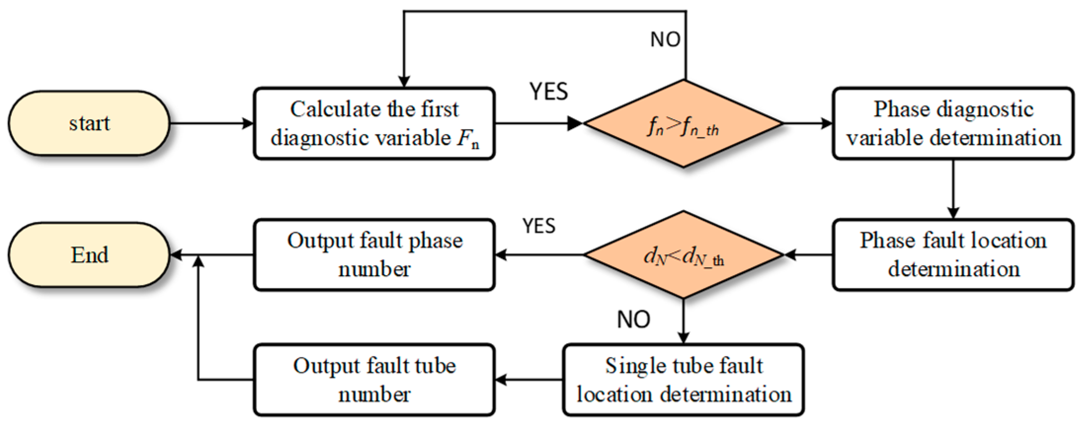
In this section, we propose a novel method for diagnosing multiple open-circuit faults in the OPF system based on the dual d–q predicted current model, as depicted in Figure 5. In this paper’s electrical fault diagnosis, we present a two-step diagnostic scheme. Firstly, system faults are identified by monitoring the fault indicator Fn. Secondly, the phase sequence of open-circuit faults is determined through the fault phase indicator DN. It is possible to locate the specific faulty transistor by evaluating the magnitude of the inverter fault indicator TM corresponding to inverter PINs 1 to 12.
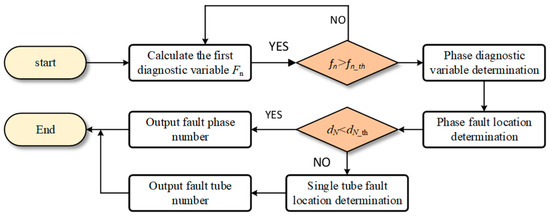
Figure 5.
Flowchart of the diagnosis process.
4.1. Fault Current Model
Under normal operation, the predicted current in the (k + 1)th sampling interval can be derived from the current in the kth sampling interval according to Equation (3). If there is a fault, the predicted current in the (k + 1)th sampling interval predicted by the normal model will deviate from the feedback current. First, the correct predicted current in the fault operation needs to be calculated for fault diagnosis.
The stator voltage of a dual three-phase permanent magnet synchronous motor is expressed as
U6s, I6s, ψ6s, and R6s represent the six-phase stator voltage vector, phase current vector, magnetic flux linkage, and stator resistance, respectively.
Because of the neutral isolation, each winding can be treated as an independent winding. The phase-current relation can be changed as follows
Assuming that the A-phase current will be forced to zero in case of an open-circuit fault in the A phase. According to Kirchhoff’s law, the relationship between the B-phase current and the C-phase current can be expressed as follows
According to Equations (6) and (8), the line voltage between phases B and C under A-phase OPF can be expressed as
Through the discretization processing of Equation (3), it can be obtained that
According to Equation (10), the predicted B-phase current during the (k + 1)th sampling interval under A-phase OPF operation can be represented as
Thus, using Park transformation, the predictive current in the d1q1 axis of the OPF model under the A-phase OPF constraint can be derived from Equations (7) and (11), expressed as
Similarly, when an open-circuit fault occurs in the U phase, the fault current constraint can be expressed as
Under the constraint of the U-phase fault current, the predictive current in the d2–q2 axis of the OPF model under the U-phase OPF constraint can be derived
Due to the spatial symmetry of the windings in a dual three-phase permanent magnet synchronous motor, the dual dq-axis predictive current model under the other phase’s OPF constraints can be obtained by adjusting the angles according to Equations (12) and (14). In summary, the fault current model can be represented by the formulas (15) and (16)
In the equation, the variables are as follows: n = (A, B, C); n* = (B, A, A); ω = (0, 1, −1); m = (U, V, W); m* = (V, U, U); λ = (−1, 1, 0).
4.2. Determination of Fault Occurrence
According to the analysis of fault current in Section 3, the current trajectories of OPF and OSF have the same trajectory characteristics in the harmonic plane, so they can be used for fault determination. The harmonic predicted current vector mode is defined as
Define fn as an intermediate variable for fault detection. Under normal conditions, ix and iy are nearly zero, keeping fn close to zero. In the event of various open-circuit faults, the harmonic currents exhibit a predictable distribution, causing the magnitude of the vector to significantly deviate from zero. Consequently, monitoring changes in fn can enable rapid fault detection.
To reduce the effects of random noise in time series data, a moving average filter is used to smooth the signal waveform. Post-filtering, the filtered value fn_mean is assigned to fn as a basis for fault detection in the algorithm.
In the experiment described in this paper, the index fn has a maximum error of about 0.2 A during normal operation. To avoid misdiagnosis and ensure sufficient safety margin, the threshold of the index fn_th is set to 0.3 A. When fn_mean is greater than the threshold, the system is determined to be in fault and the fault index Fn = 1 is output.
4.3. Identification of Faulty Phase
As shown in Figure 5, the first step of the fault diagnosis process, Fn, determines whether the system is at fault. The second step of the fault diagnosis process narrows the fault search range to specific faults, such as single inverter OSF and single-phase OPF.
Under fault, the feedback currents of the fault model of axis d1–q1 in the (k + 1)th sampling interval are almost the same as the predicted currents of axis d1–q1 of the normal model, which can be expressed as.
According to Equation (20) the equation of residual currents of planar fault prediction current and health prediction current under the constraint of A- and U-phase OPF is obtained as follows
Take the residual current vector mode and construct the intermediate variables dA and dU for phase diagnosis
The A-phase fault can be analyzed using Formula (21) to define two intermediate variables for phase location of winding faults, denoted as dN (f = A, B, C; s = U, V, W).
The intermediate variables of fault phase location of two sets of windings are processed by sliding average filtering, respectively, and the filter dN_mean is assigned to dN in the algorithm.
In the fault state, the residual model of the fault-predicted current is close to equal, and the residual vector modulus dA and dU under the fault is close to zero. In the healthy state of the system, dA will be greater than zero, and they are constant positive half-wave functions. Therefore, by observing the changes of dN and dN_th, the fault phase can be quickly positioned, and the waveforms of the intermediate variables fn and dN under different faults are shown in Table 1.

Table 1.
Time-domain fault variable waveform under different faults.
4.4. Determination of Specific Fault Type
When the judgment condition satisfies the constraint conditions of fn > fn_th and dN < dN_th, according to the judgment of the condition statement, the model will move to the positioning stage of the switch tube fault location. Here, “fn > fn_th” refers to the first diagnostic variable indicator indicating that the system has a fault, while “dN < dN_th” indicates that the phase fault indicator does not change and there is no open-circuit fault. At this point, it indicates that the system has a fault but not an open-circuit fault, that is the switch tube open-circuit fault. The model will execute the switch tube positioning program to determine the specific fault tube position.
The reference angle of the harmonic current vector at each phase fault can be described as follows
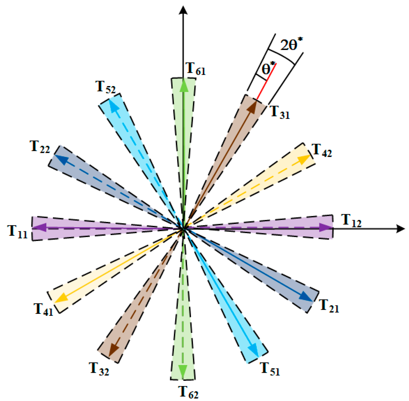
The analysis in Section 3 reveals that the harmonic plane current trajectories undergo systematic variations when an OSF occurs, depending on the position of the faulty switch tube. Figure 6 presents a diagram illustrating the segmentation of current vector trajectories under a single-tube fault, (where A+ denotes the upper switch of phase A and A− represents the lower switch of phase A).
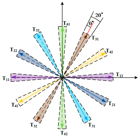
Figure 6.
Position angle of ix–iy current track corresponding to inverter open-circuit fault.
To overcome the effects of non-ideal factors during the actual operation of the system, a safety threshold θ* is added to the ideal position of the current trajectory. This ensures that once the diagnosis method calculates the current trajectory position as satisfying Equation (24), the position of the faulty switch can be determined. The selection of θ* should be based on the actual operation of the system, and in this experiment, θ* is chosen to be 5°.
As shown in Figure 6, the faulty tube position can be accurately identified by determining the position angle tM of the harmonic current trajectory within the corresponding error interval.
5. Experimental Verification
5.1. Experiment System
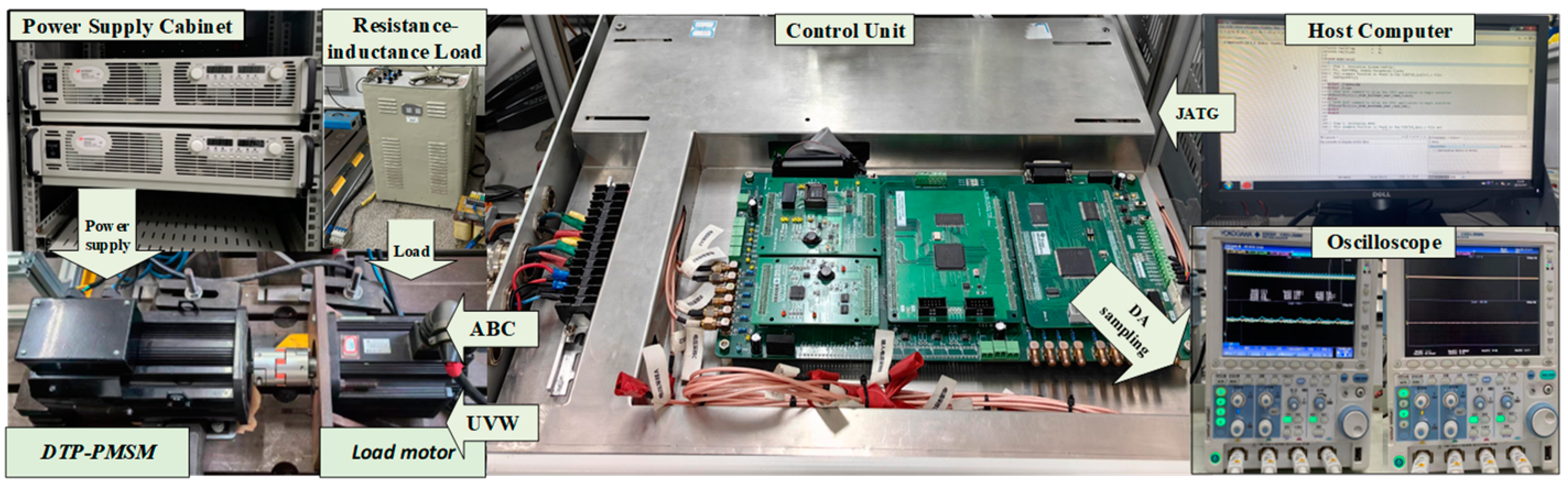
The diagnostic strategy’s efficacy was validated through experiments conducted on a DTP-PMSM. The experimental platform is shown in Figure 7 The experimental platform demonstrates the functions and interrelationships of the various parts of the system.
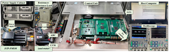
Figure 7.
Experimental platform for DTP-PMSM control system.
Key motor parameters include: rated power of 4 kW; peak current of 3.5 A; rated speed of 1000 r/min; and stator resistance Rs 1.45 Ω. The control system’s core is constructed using TI TMS320F28379 DSP of USA and Intel’s FPGA MAX-V chip of USA. During the experiment, a switching frequency of 10 kHz was employed, with load provided by the PMSM while vector control and fault diagnosis algorithms were implemented through DSP technology. Fault simulation was achieved by blocking corresponding pulse drive signals.
5.2. Transient Performance Analysis
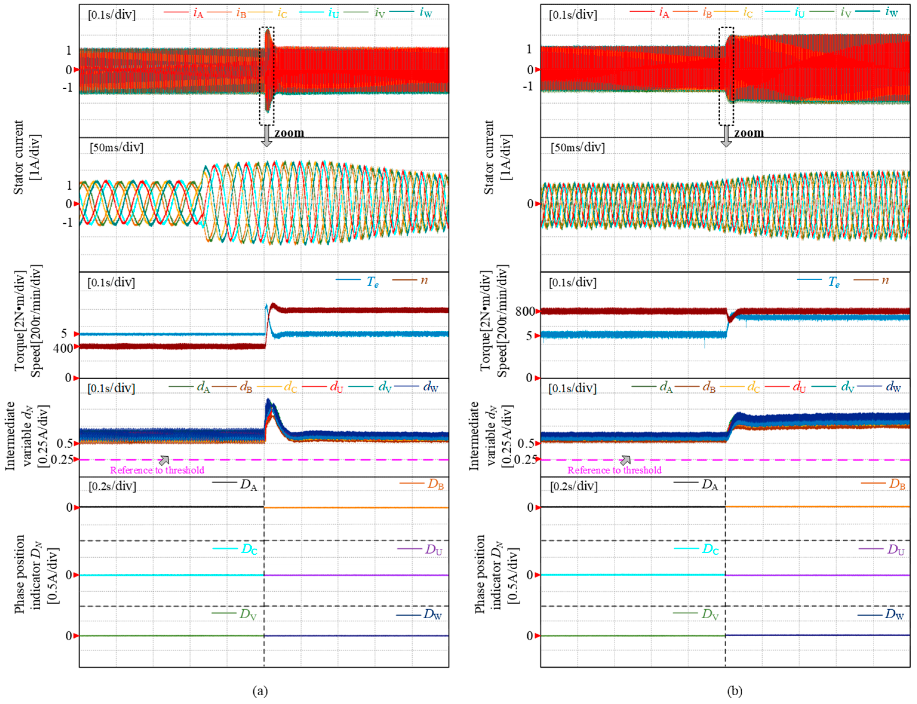
Experimental validations were conducted to assess the robustness of the proposed fault diagnosis scheme during transient operations, specifically evaluating speed and load response. Figure 8a depicts an acceleration experiment where a constant torque of 5 N·m was applied, increasing the speed from 400 r/min to 800 r/min within 0.5 s after achieving stable operation for a certain duration. Throughout the variable-speed process, transient step phenomena were observed in the intermediate variables. In the load variation experiment shown in Figure 8b, after accelerating and maintaining a stable speed of 800 r/min for a specific period, the load was abruptly increased to 8 N·m within 0.5 s due to loading effects. This led to an increase in phase current amplitude and intermediate variables, resulting in changes in motor speed and load; however, these variations did not affect fault diagnosis as protection strategies employed an undershoot threshold setting method. During the testing period, all intermediate variables consistently remained above their thresholds while the fault detection index DN consistently maintained a zero value, thereby validating both the effectiveness and stability of this diagnostic approach during transient operations.
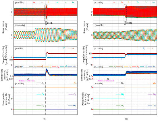
Figure 8.
Health state transient waveform. (a) Acceleration under constant load; (b) constant speed loading.
5.3. Dynamic Performance Analysis
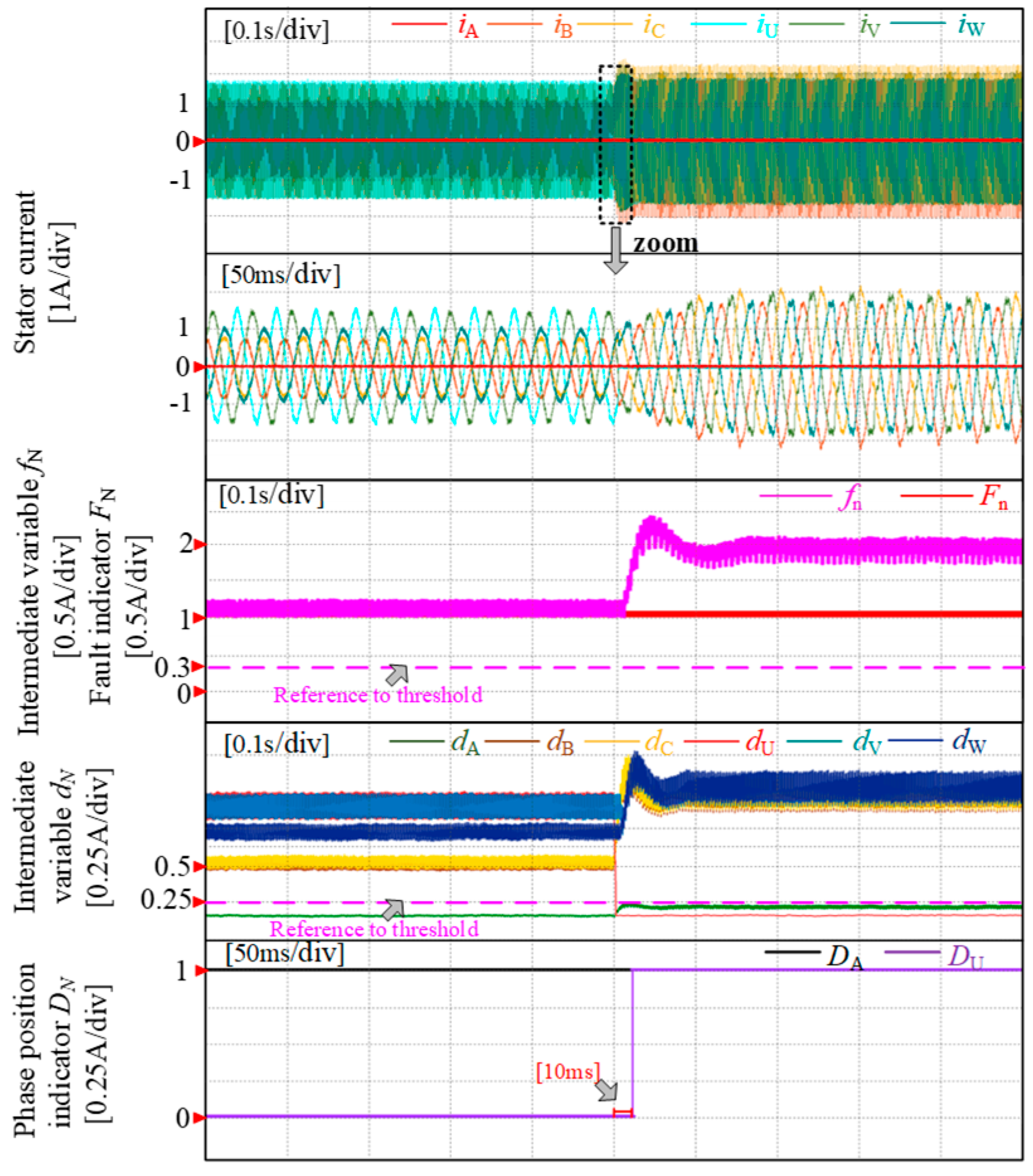
Figure 9 depicts the experiment of fault diagnosis in the PMSM drive system under open-circuit fault conditions in phase A. During normal operation, the phase A current exhibits a sinusoidal waveform with the fault occurrence index fn significantly below its threshold fn_th. However, when an open-circuit fault occurs in phase A, the current drops to zero and remains constant. At this point, the fault occurrence index briefly exceeds its threshold fn_th, resulting in the transition of the fault flag Fn from 0 to 1 within 5 ms, indicating that a fault has occurred and completing the first diagnostic step. After an open-circuit fault occurs in phase A, intermediate variable dA rapidly decreases below its threshold and causes a surge of DA from 0 to 1 within 10 ms signifying the completion of the diagnostic process. Additionally, all five intermediate variables dA−dV remain above their thresholds confirming no false positives during diagnosis.
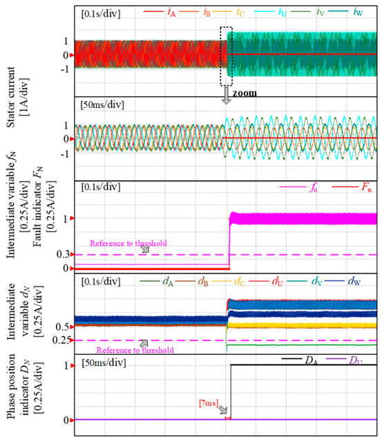
Figure 9.
Fault diagnosis of phase—A OPF.
The fault diagnosis experiment of loading a U-phase open-circuit PMSM drive with an A-phase open-circuit fault is depicted in Figure 10. Under normal operating conditions, the fault occurrence index fn remains significantly lower than its threshold value fn_th. However, when the U-phase experiences OPF following the A-phase, throughout the entire process, the fault occurrence index fn consistently exceeds the threshold value fn_th, indicating that the initial step of diagnosis is always responsive. Before the U-phase fault, the phase indicator DA consistently remains at 1; after the fault occurs, dU rapidly decreases. Within 7 ms, the fault phase indicator DU transitions from 0 to 1, signifying completion of the diagnostic process. Throughout this process, four additional intermediate variables dB~dC and dV~dW all surpass their thresholds while indicators dB~dC and dV~dW remain zero; thus ensuring no misjudgment in this procedure.
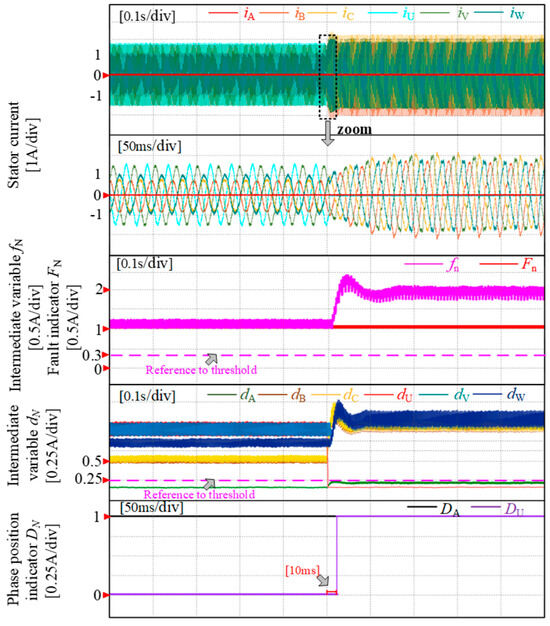
Figure 10.
Fault diagnosis of phase—A and U OPF.
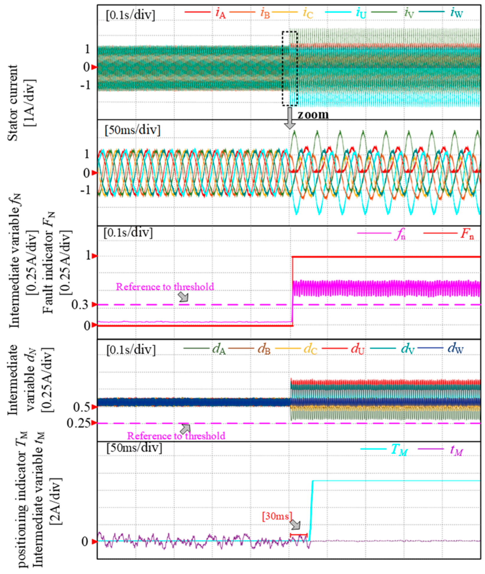
The fault diagnosis experiment of the open-circuit fault in the PMSM drive system is illustrated in Figure 11, focusing on the A-phase switching tube T12. Under normal operation, the A-phase current exhibits a sinusoidal waveform with an occurrence index fn significantly below the threshold fn_th. However, when T12 experiences an open-circuit fault, the A-phase current drops to zero during the negative half cycle and approximates a sine waveform during the positive half cycle. Simultaneously, there is a momentary increase in the fault occurrence index fn above its threshold fn_th value, leading to a transition of fault flag Fn from 0 to 1 indicating completion of the initial diagnostic step. Furthermore, as evidenced by the phase positioning index dN surpassing its threshold value, it can be determined that this is a single inverter fault with the identified position. Upon confirming T12 open-circuit fault condition, TM fault flag changes from 0 to 7 within 28 ms signifying the completion of the diagnostic process and determination of the seventh pin (i.e., lower bridge arm of A-phase) as a faulty location.
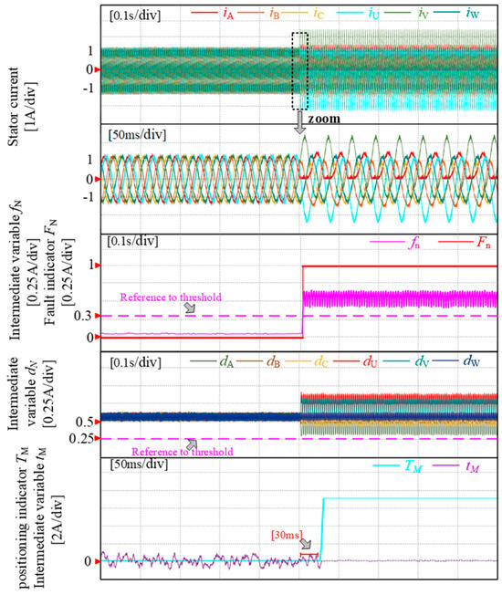
Figure 11.
Fault diagnosis of SA1–OSF.
5.4. Parametric Disturbance Analysis
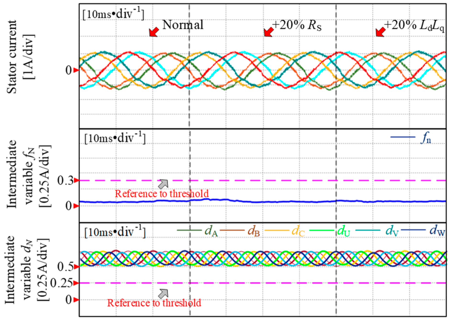
The stability of the diagnostic strategy is verified by introducing a 20% error separately in the d–q axis inductance and stator resistance and observing its impact on the diagnostic results. As depicted in Figure 12, parameter deviations cause minimal fluctuation in the waveform of intermediate variables during fault occurrence, which is significantly smaller than the maximum error of 0.1 A under normal conditions. The diagnostic intermediate variables fn are much smaller than the threshold fn_th, while the phase diagnostic intermediate variables dn are much larger than the threshold dN_th. Based on this analysis, it can be concluded that when parameter errors are introduced during healthy motor operation, the diagnostic algorithm performs well, and intermediate variable values remain considerably lower than their preset thresholds fn_th and dN_th. This demonstrates that parameter disturbances do not affect diagnosis.
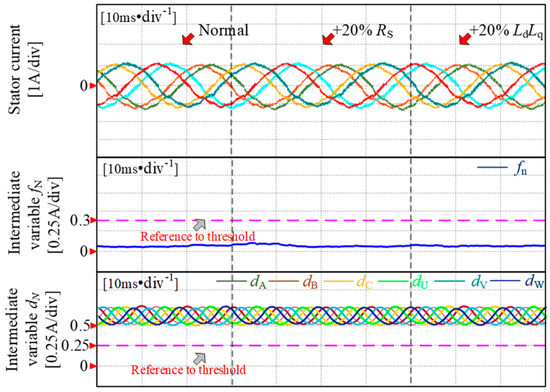
Figure 12.
Comparison of parameter disturbance.
6. Conclusions
This study addresses the problem of incorrect fault diagnoses that frequently occur in a dual three-phase permanent magnet synchronous motor during load steps, idling, or at low load. An open-circuit fault diagnosis strategy is proposed to improve robustness. The theoretical analysis and experimental validation confirm the results:
- (1)
- This strategy can diagnose three types of open-circuit faults in the DTP-PMSM drive system, including 12 fault types for OSF and 21 fault types for single-phase and two-phase OPF, making a total of 33 fault types. And, it can also diagnose single-phase open faults and two-phase open faults simultaneously.
- (2)
- The strategy effectively overcomes the issue of misjudgment in load mutation encountered by traditional methods, The empirical verification has confirmed the demonstrating high reliability and robustness in diagnosing open-circuit faults. The diagnosis time for OPF and OSF in the system is within 10 ms and 30 ms, respectively.
- (3)
- After simplifying the calculation process, the strategy of this paper achieves that there is no interference between the different diagnostic variables in the compatible diagnosis of multiphase open-circuit faults. Furthermore, this strategy does not require additional hardware support and can perform fault diagnosis quickly and accurately even when operating points, control strategies or drive parameters change.
- (4)
- This strategy employs the approach of utilizing predicted current extraction to construct fault models, which acts as a link between fault diagnosis and fault-tolerant control based on predicted current, providing certain support for future research on a dual three-phase permanent magnet synchronous motor’s fault-tolerant control and laying part of the foundation.
Author Contributions
Conceptualization, Q.G.; data curation, W.D.; formal analysis, G.Z.; funding acquisition, Z.Z. and Q.G.; investigation, X.J.; methodology, Z.Z.; project administration, Q.G.; resources, Q.G.; software, X.J.; supervision, G.Z. and Q.G.; validation, X.J.; visualization, W.D.; writing—original draft, W.D. All authors have read and agreed to the published version of the manuscript.
Funding
This research was supported in part by the National Natural Science Foundation of China under Grant 52077154, in part by the Natural Science Foundation of Tianjin Municipality under Grant 23JCYBJC00290, and in part by the Zhejiang Provincial Natural Science Foundation of China under Grant LY24E070003.
Institutional Review Board Statement
Not applicable.
Informed Consent Statement
Not applicable.
Data Availability Statement
The original contributions presented in the study are included in the article, further inquiries can be directed to the corresponding author.
Conflicts of Interest
The authors declare no conflict of interest.
References
- Levi, E. Advances in converter control and innovative exploitation of additional degrees of freedom for multiphase machines. IEEE Trans. Ind. Electron. 2015, 63, 433–448. [Google Scholar]
- Wu, G.; Huang, S.; Wu, Q.; Rong, F.; Zhang, C.; Liao, W. Robust Predictive Torque Control of N*3-Phase PMSM for High-PowerTraction Application. IEEE Trans. Power Electron. 2020, 35, 10799–10809. [Google Scholar]
- Riaz, S.; Qi, R.; Tutsoy, O. A novel adaptive PD-type iterative learning control of the PMSM servo system with the friction uncertainty in low speeds. PLoS ONE 2023, 18, 1932–6203. [Google Scholar] [CrossRef]
- Ping, Z.; Wang, T.; Huang, Y.; Wang, H.; Lu, J.G.; Li, Y. Internal model control of PMSM position servo system: Theory and experimental results. IEEE Trans. Ind. Inform. 2020, 16, 2202–2211. [Google Scholar]
- Li, L.N.; Zhu, G.J. Electromagnetic-thermal-stress efforts of stator-casing grease buffers for permanent magnet driving motors. IEEE Trans. Ind. Appl. 2024, 60, 1268–1276. [Google Scholar] [CrossRef]
- Kommuri, S.K.; Defoort, M.; Karimi, H.R.; Veluvolu, K.C. A robust observer-based sensor fault-tolerant control for PMSM in electric vehicles. IEEE Trans. Ind. Electron. 2016, 63, 7671–7681. [Google Scholar]
- Choi, U.M.; Blaabjerg, F.; Lee, K.B. Study and handling methods of power IGBT module failures in power electronic converter systems. IEEE Trans. Power Electr. 2014, 30, 2517–2533. [Google Scholar]
- Wang, X.; Wang, Z.; Xu, Z. Comprehensive diagnosis and tolerance strategies for electrical faults and sensor faults in dual three-phase PMSM drives. IEEE Trans. Power Electron. 2018, 34, 6669–6684. [Google Scholar]
- Choi, U.M.; Lee, K.B.; Blaabjerg, F. Diagnosis and tolerant strategy of an open-switch fault for T-type three-level inverter systems. IEEE Trans. Ind. Appl. 2013, 50, 495–508. [Google Scholar]
- Choi, U.M.; Jeong, H.G.; Lee, K.B. Method for detecting an open-switch fault in a grid-connected NPC inverter system. IEEE Trans. Power Electron. 2011, 27, 2726–2739. [Google Scholar]
- Li, H.; Guo, Y.; Xia, J.; Zhang, X. Open-circuit fault diagnosis for a fault-tolerant three-level neutral-point-clamped STATCOM. IET Power Electron. 2019, 12, 810–816. [Google Scholar]
- Lee, J.S.; Lee, K.B.; Blaabjerg, F. Open-switch fault detection method of a back-to-back converter using NPC topology for wind turbine systems. IEEE Trans. Ind. Appl. 2014, 51, 325–335. [Google Scholar]
- Shi, T.; He, Y.; Deng, F.; Shi, L. Online diagnostic method of open-switch faults in PWM voltage source rectifier based on instantaneous AC current distortion. IET Electric Power Appl. 2018, 12, 447–454. [Google Scholar]
- Shi, T.; He, Y.; Wang, T.; Deng, F. An improved open-switch fault diagnosis technique of a PWM voltage source rectifier based on current distortion. IEEE Trans. Power Electron. 2019, 34, 12212–12225. [Google Scholar]
- Wu, F.; Zhao, J. Current similarity analysis-based open-circuit fault diagnosis for two-level three-phase PWM rectifier. IEEE Trans. Power Electron. 2016, 32, 3935–3945. [Google Scholar]
- Guo, H.; Guo, S.; Xu, J.; Tian, X. Power switch open-circuit fault diagnosis of six-phase fault tolerant permanent magnet synchronous motor system under normal and fault-tolerant operation conditions using the average current Park’s vector approach. IEEE Trans. Power Electron. 2020, 36, 2641–2660. [Google Scholar]
- Xu, J.; Tian, X.; Jin, W. Pwm harmonic-current-based interturn short-circuit fault diagnosis for the aerospace FTPMSM system even in the fault-tolerant operation condition. IEEE Trans. Power Electron. 2023, 38, 5432–5441. [Google Scholar]
- Wang, B.; Li, Z.; Bai, Z.; Krein, P.T.; Ma, H. A voltage vector residual estimation method based on current path tracking for T-type inverter open-circuit fault diagnosis. IEEE Trans. Power Electron. 2021, 36, 13460–13477. [Google Scholar]
- De Araujo Ribeiro, R.L.; Jacobina, C.B.; Da Silva, E.R.C.; Lima, A.M.N. Fault detection of open-switch damage in voltage-fed PWM motor drive systems. IEEE Trans. Power Electron. 2003, 18, 587–593. [Google Scholar]
- Wu, X.; Chen, C.Y.; Chen, T.F.; Cheng, S.; Mao, Z.H.; Yu, T.J.; Li, K. A fast and robust diagnostic method for multiple open-circuit faults of voltage-source inverters through line voltage magnitudes analysis. IEEE Trans. Power Electron. 2019, 35, 5205–5220. [Google Scholar]
- Hang, J.; Zhang, J.; Cheng, M.; Ding, S. Detection and discrimination of open-phase fault in permanent magnet synchronous motor drive system. IEEE Trans. Power Electron. 2015, 31, 4697–4709. [Google Scholar]
- Yin, H.; Chen, Y.; Chen, Z.; Li, M. Adaptive fast fault location for open-switch faults of voltage source inverter. IEEE Trans. Circ Syst. I Reg Papers. 2021, 68, 3965–3974. [Google Scholar]
- Zhang, W.; He, Y. A hypothesis method for t-type three-level inverters open-circuit fault diagnosis based on output phase voltage model. IEEE Trans Power Electron. 2022, 37, 9718–9732. [Google Scholar] [CrossRef]
- Cheng, Y.; Sun, Y.; Li, X. Active common-mode voltage-based open-switch fault diagnosis of inverters in im-drive systems. IEEE Trans Ind Electron. 2021, 68, 103–115. [Google Scholar] [CrossRef]


Disclaimer/Publisher’s Note: The statements, opinions and data contained in all publications are solely those of the individual author(s) and contributor(s) and not of MDPI and/or the editor(s). MDPI and/or the editor(s) disclaim responsibility for any injury to people or property resulting from any ideas, methods, instructions or products referred to in the content. |
© 2024 by the authors. Licensee MDPI, Basel, Switzerland. This article is an open access article distributed under the terms and conditions of the Creative Commons Attribution (CC BY) license (https://creativecommons.org/licenses/by/4.0/).