Abstract
In this paper, a flux–torque regulation hybrid excitation machine (FTRHEM) with axial–radial dual air gaps, which can increase torque and regulate magnetic flux by changing the exciting current, is studied. Dual air gaps have a huge impact on the magnetic flux and additional torque. The effect of the air gap reluctances on the magnetic flux of the machine is obtained by establishing equivalent magnetic network models, which show that the dual air gaps are the key component in the axial–radial magnetic circuit. This study examines the flux regulation ability and the enhanced torque performance of an FTRHEM with dual air gaps. The mechanism by which the dual air gaps affect the machine’s magnetic field is clarified, and the constraints and relationships between the dual air gaps are explained, offering a theoretical foundation for future machine optimization. As the axial air gap decreases from 0.95 mm to 0.35 mm, the flux regulation capability improves from 15.44% to 26.51%, while the additional torque increases by 40.77%. Ultimately, prototypes are manufactured for experimental testing to validate the viability of the structure and the accuracy of the FEA for the FTRHEM featuring an axial–radial magnetic circuit.
1. Introduction
Permanent magnet synchronous machines (PMSMs) have the outstanding advantages of a simple structure and high efficiency [1]. However, the constant magnetomotive force (MMF) of permanent magnets (PMs) leads to difficulties in magnetic field regulation, which limits the application of PMSMs [2]. The excitation source of the hybrid excitation machine (HEM) is composed of PM and field windings [3]. Therefore, the HEM has the advantages of high efficiency, easy flux regulation, and great application prospects in the field of electric vehicles [4].
The structures of HEMs are diverse because of field windings, which can be placed in the rotor, end, and stator [5]. Reference [6] presented a new partitioned stator doubly salient HEM, with armature in the outer stator and field windings in the inner stator. The effect of the inner stator’s yoke on the electromagnetic capability was studied by the equivalent magnetic circuit method. Reference [7] introduced a HEM featuring field winding situated in its axial section. The N and S poles of the rotor extended along the axis outward and inward, respectively, forming a closed magnetic circuit in the axial part and a brushless excitation structure. Reference [8] proposed a consequent pole brushless HEM, with field winding integrated into the rotor to improve fault tolerance.
The air gap is the medium for energy conversion, so the selection of the air gap is critical to the machine. An appropriate air gap not only minimizes harmonic and stray losses in the machine, but also significantly boosts its power factor and efficiency [9,10]. Reference [11] investigated the influence of the air gap on the machine (45 kW and 6000 rpm). Reference [12] calculated the cogging torque of an axial flux (AF) machine under abnormal air gap conditions by combining analytical and numerical methods, and found a significant degree of distortion in each method’s peak and period of the cogging torque curve. The properties of a DS-PMLSM with an air gap were investigated in reference [13]. As the thickness of the air gap increases, the fundamental amplitude of the no-load back electromotive force (EMF) diminishes over operating cycles. Reference [14] proposed and investigated two HEMs with different air gap features. The axial auxiliary air gap scheme and the radial air gap scheme were compared and studied.
At present, the research on air gaps in machines is mainly focused on induction motors, PM machines, and HEMs with DC excitation. Research results for the air gaps of HEMs with AC excitation are less available, and the distribution and constraints of double air gaps are also unanalyzed. FTRHEM has great application prospects in electric vehicles because of its good flux regulation ability and torque capability.
This paper studies a new FTRHEM featuring an axial–radial magnetic circuit. Not only is the air gap magnetic field regulated using field winding, but additional torque is added by using the interaction of the leakage magnetic field of the rotor. The effect of the air gaps on the performance is studied for the dual air gaps of this machine. First, the machine’s magnetic flux equations are derived by using equivalent magnetic network models to determine the effect of the axial/radial air gap reluctance on the magnetic flux. Second, the effects of the radial air gap and axial air gap on the machine’s flux regulation capability and additional torque are studied by determining the mechanisms of the effects of the axial/radial air gap lengths on the machine’s magnetic field. Third, the differences in the effects of the axial/radial air gaps on the magnetic field are clarified, to provide theoretical support for the subsequent optimization. Finally, the prototype is manufactured for experimental tests, to verify the enhancement of additional torque and flux regulation capability in the FTRHEM.
2. Topology and Operating Principle of the FTRHEM
2.1. Machine Topology
A new HEM with flux–torque regulation and an axial–radial magnetic circuit, as shown in Figure 1, has been studied. The FTRHEM comprises a spoke-type interior PM rotor, a stator, and two axial structures located on both sides of the rotor. Each axial structure includes two rings, a field winding, and an end cap. There are five alternating claw poles on each ferromagnetic ring. The space between the ring and the rotor, referred to as the additional air gap, is known as the axial air gap. Conversely, the space between the rotor and the stator, the main air gap, is called the radial air gap. The excitation flux is produced by the field winding with alternating current (AC) situated in the groove of the end cap, which not only modulates the magnetic field, but also interacts uniquely with the PM magnetic field to produce additional torque. The dual air gaps are a crucial element in regulating the torque and flux.
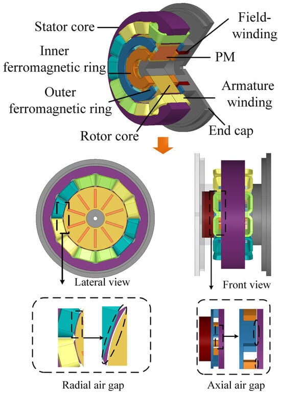
Figure 1.
Lateral and front views of the FTRHEM.
2.2. Principle of Machine Flux Regulation Based on Magnetic Network
The principle of flux regulation is that the d-axis magnetic flux, generated by the alternating field winding MMF, enters the main air gap through the ferromagnetic ring to regulate the magnetic field within that gap. A portion of the magnetic flux produced by the PM traverses the axial section, resulting in magnetic flux leakage, commonly referred to as the bypass effect. The flux-weakening mechanism is shown in Figure 2a. As the ferromagnetic ring remains stationary while the rotor rotates, the rotor pole area corresponding to the claw pole of the ring undergoes periodic changes. The direction of the d-axis magnetic flux in the claw pole also changes periodically because of the alternating current. The flux regulation mode can be regulated by changing the direction of the axial d-axis current influenced by the current phase. According to the direction of the axial d-axis flux, the operating model of the motor can be divided into three types, which are presented in Figure 2a–c [15].
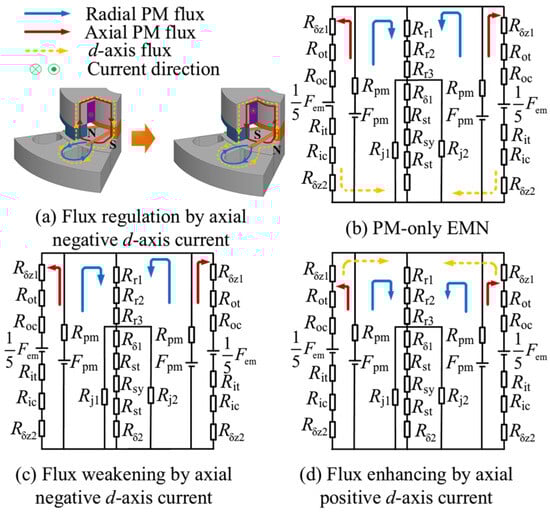
Figure 2.
Principle of flux regulation by axial d-axis flux.
To better analyze the effects of air gaps, equivalent magnetic networks (EMNs) were established according to the operating mode of the machine. The reluctances and d-axis flux paths are presented in Figure 2b–d. The main air gap fluxes in each mode of the machine are calculated in Equation (1). The symbols and meanings of the special reluctance and MMF are shown in Table 1.
where , , and are the main air gap fluxes for each of the three modes. The axial air gap reluctances and are directly proportional to , and the radial air gap reluctance is directly proportional to .

Table 1.
Meaning of reluctance and MMF.
Owing to the uneven distribution of magnetic density, the rotor reluctance is divided into three parts along the radial direction, namely , , and .
In Table 2, the relationship between the main air gap flux and both and is obtained from (1) and (2), where “” and “” indicate an increase and a decrease in value, respectively, “” indicates a constant value, and the blank indicates an uncertain change in value. Figure 2 shows that the main air gap flux is affected differently by the radial/axial air gap reluctance in each mode. The d-axial magnetic flux decreases with increasing radial air gap reluctance in both the flux-enhancing mode and the PM-only mode. With increases in the axial air gap reluctance, the d-axial magnetic flux increases in the flux-weakening mode and the PM-only mode, and the d-axial magnetic flux decreases in the flux-enhancing mode.
Table 2.
Changes in magnetic flux with and .
2.3. Principle of Additional Torque
When AC is applied to the field winding, the direction of the magnetic field in the ferromagnetic ring changes periodically. Additional torque can be produced by changing the q-axis flux in the ferromagnetic ring’s interaction with the magnetic axial leakage. The additional torque can be categorized into two types: driving torque and braking torque, with the specific type determined by the direction of the q-axis current. As shown in Figure 3, because the direction of the q-axis current is different, the direction of the flux in the ferromagnetic ring is different, which leads to the direction of the torque being different. When the direction of the torque is the same as the direction of rotation of the rotor, the additional torque is of the driving type. In contrast, it is of the braking type [16].
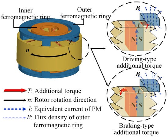
Figure 3.
Principle of additional torque generation by axial q-axis flux.
From the above, the axial current of the motor can be divided into d-axis and q-axis components, whose size and direction can be changed by changing the amplitude and phase of the axial current, which control the flux and torque of the motor, respectively. It is the air gap, as an important part of the magnetic circuit, that has a significant impact on the flux and torque.
3. Study of the Air Gap’s Effect on the Performance of the FTRHEM
3.1. Air Gap Equivalent Models
Because the air gap has a crucial impact on flux regulation, the mechanisms of its effects on the flux and torque are investigated. Figure 4 shows the dimensions and the dual air gap equivalent models. The axial air gap magnetic reluctance model is equated to a sector shape, according to the shape of the claw pole in the ferromagnetic ring. Equation (3) demonstrates that the air gap reluctance is influenced by the air gap area and length, and this section studies the effect of air gap length on machine performance.
where is the radial air gap length, and are the axial air gap lengths and are equal, is the stator core length, is the stator tooth width, and is the air permeability.
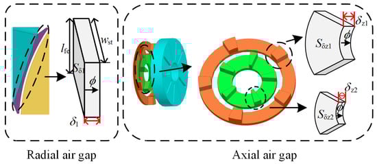
Figure 4.
Air gap equivalent models and dimensions.
The effects of the axial air gap and the radial air gap on the flux regulation and torque regulation performance of motors are analyzed.
3.2. The Influence of the Air Gap on the Flux Performance
The flux and torque performances are the focus of this study on the FTRHEM. The flux regulation capability is assessed through the EMF, and the torque improvement capability is reflected by the additional torque value.
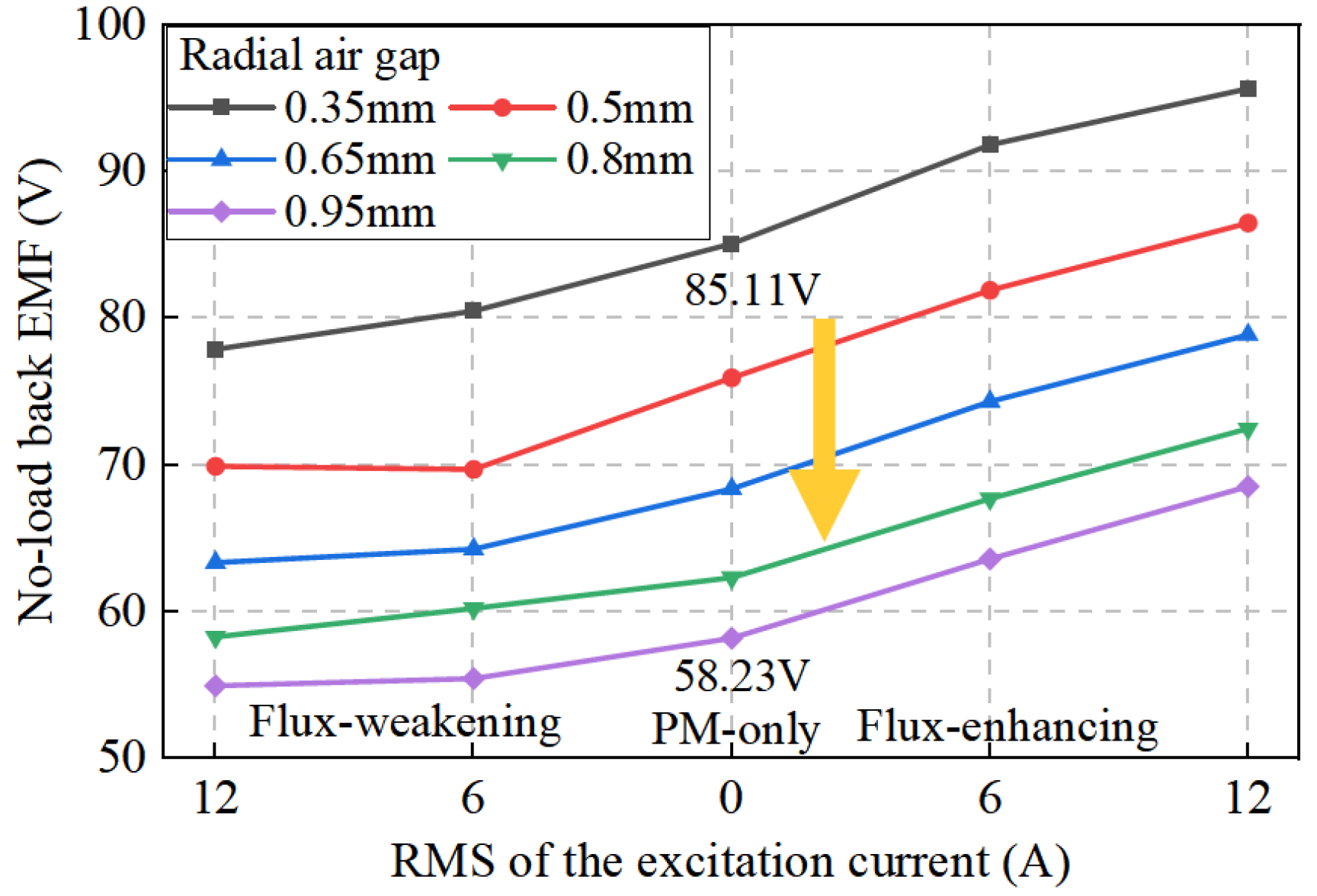
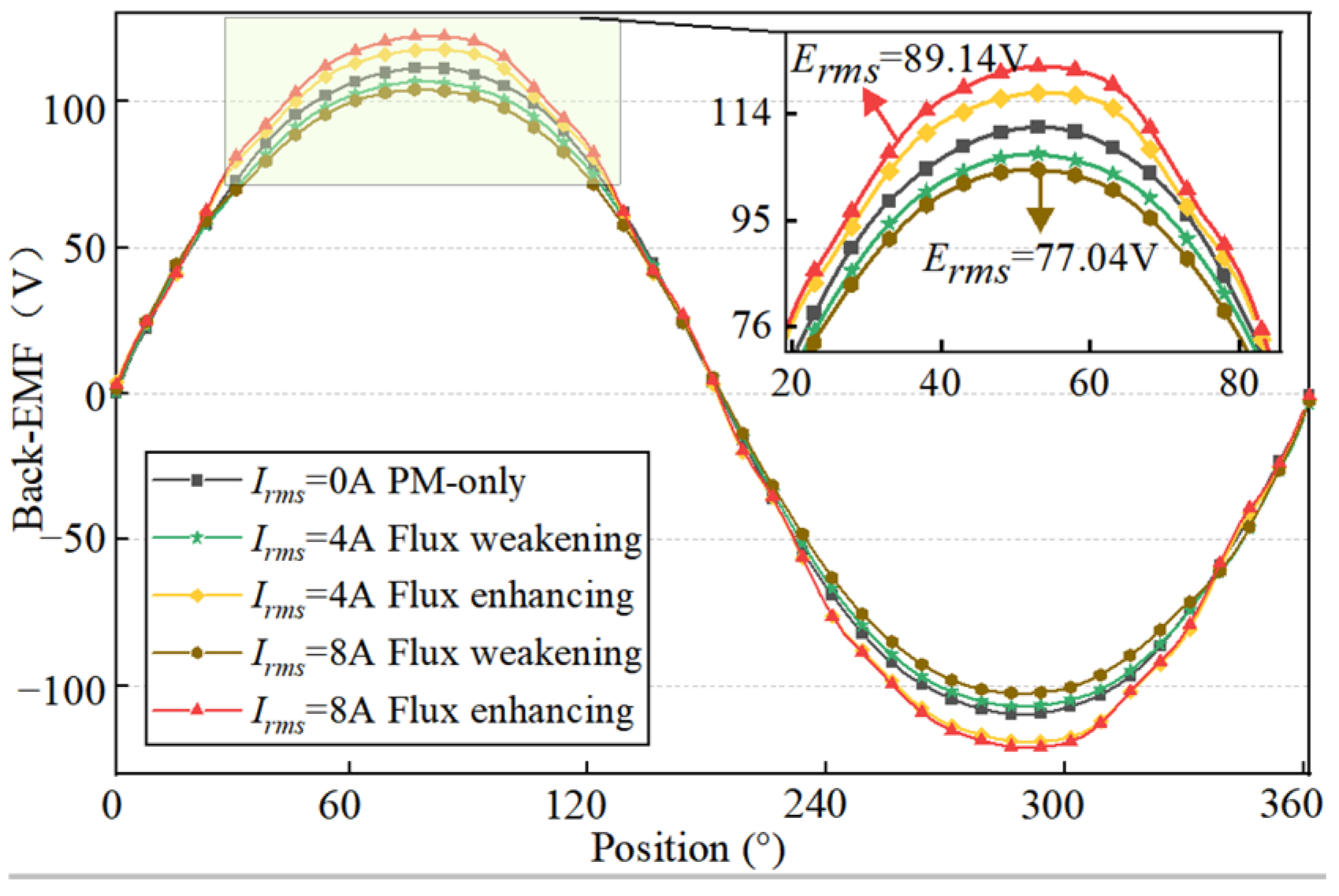
The curves of the EMF with different excitation currents and radial air gap lengths are shown in Figure 5. Part of the magnetic flux produced by the PM does not interlink with the stator, but forms leakage flux through the axial magnetic circuit, weakening the main air gap flux, which is called the bypass effect.
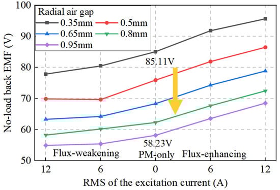
Figure 5.
Radial EMF at different radial air gap lengths.
The root mean square value (RMSV) of the EMF decreases with the rise in the radial air gap at the same excitation current. When the excitation current is 0 (the PM-only mode), the RMSV of the EMF decreases significantly with the rise in radial air gap length. When the air gap increases from 0.35 mm to 0.95 mm, the RMSV of the EMF decreases by 26.88 V. There are two reasons for the decrease in the EMF. One is that the radial air gap reluctance is larger than the axial air gap reluctance, which enhances the bypass effect of the machine, and the other is that the radial reluctance increases, resulting in a larger radial air gap magnetic potential drop.
In the flux-weakening mode, when the radial air gap length increases, the flux-weakening capability decreases. The reason for this change is that the increased bypass effect leads to magnetic saturation within the ferromagnetic ring, limiting further flux weakening. In the flux-enhancing mode, as the radial air gap length increases, the flux-enhancing capability of the machine is enhanced. The greater the length of the radial air gap, the stronger the bypass effect, which leads to enhanced flux enhancement.
The effect of the radial air gap on the axial EMF is also studied. The intensity of the bypass effect can be reflected by the axial EMF induced by the PM when there is no current in the field winding. Figure 6 shows the axial EMF for different radial air gaps. The RMSV of the axial EMF increases by 2.72 V when the radial air gap increases from 0.35 mm to 0.95 mm, due to the enhanced bypass effect as the radial air gap increases.
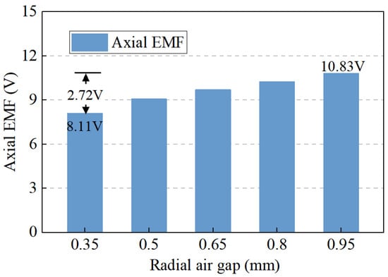
Figure 6.
Axial EMF at different radial air gap lengths.
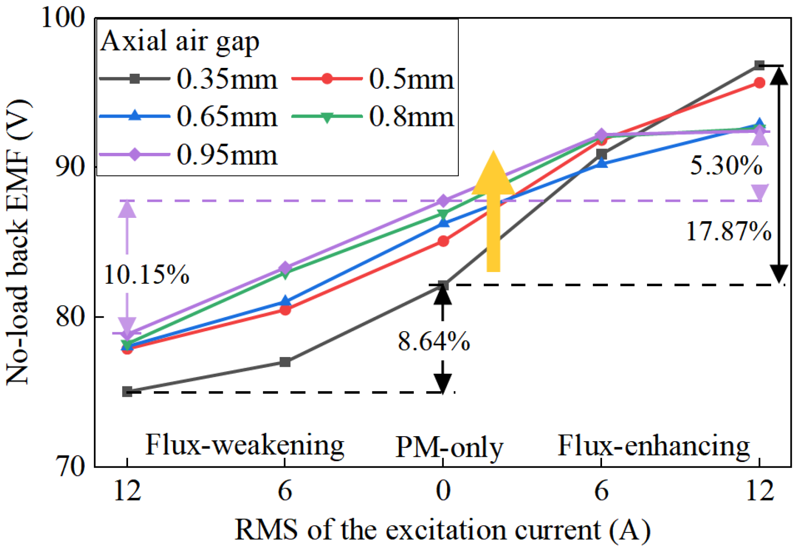
Figure 7 gives the variation curves of the EMF at different excitation currents and axial air gap lengths. In the PM-only mode, the RMSV of the EMF experiences a slight increase alongside the axial air gap. This is due to a reduction in the PM bypass effect, and the magnetic potential drop of the axial air gap has less effect on the main air gap flux.
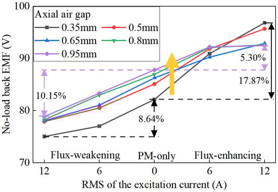
Figure 7.
Radial EMF at different axial air gap lengths.
In the flux-weakening mode, the flux-weakening capability increases alongside the axial air gap because the PM bypass effect and the saturation in the ferromagnetic ring are weakened, thus, the flux-weakening capability is enhanced.
In the flux-enhancing mode, when the AC is small, the EMF is larger with a large axial air gap. When the AC is larger, the EMF is larger for FTRHEMs with a small axial air gap length, because the axial d-axis flux counteracts the PM bypass effect first before regulating the main flux in the flux-enhancing process. The EMF of the field winding and the flux-enhancing capability decrease with increases in the axial air gap. The machine flux-enhancing range decreases from 17.87% to 5.3% when the axial air gap increases from 0.35 mm to 0.95 mm.
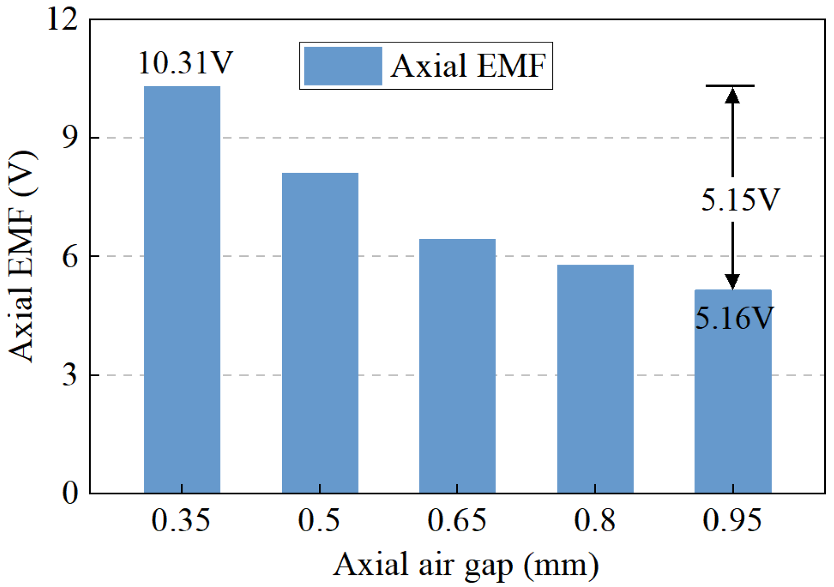
Figure 8 presents the axial EMF with different axial air gap lengths. When the length increases from 0.35 mm to 0.95 mm, the axial EMF decreases by 5.15 V because of the increase in axial magnetic potential drop, resulting in a reduction in the PM bypass effect in the axial air gap. The axial EMF is significantly decreased.

Figure 8.
Axial EMF with different axial air gap lengths.
3.3. The Influence of the Air Gap Length Ratio on the Machine Performance
To better clarify the effects of the radial air gap and axial air gap on the performance, as well as the best match and limits between the radial and axial air gaps, the air gap length ratio is defined as follows:
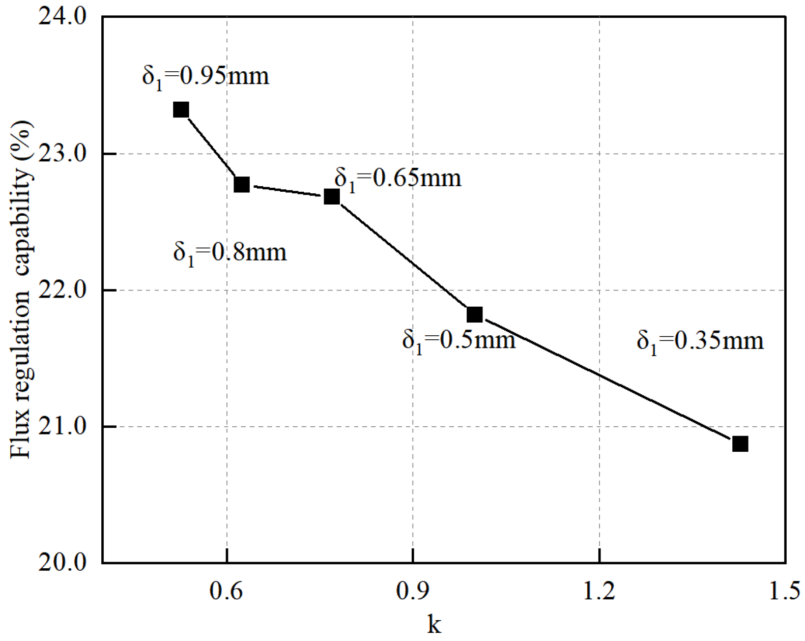
Figure 9 shows the flux regulation capability with different air gap length ratios. As the radial air gap length increases, the air gap length ratio decreases, and the machine flux regulation capability increases slightly. When is less than 1, the radial air gap is larger than the axial air gap, and the magnetic regulation capability slightly increases with the increasing radial air gap.
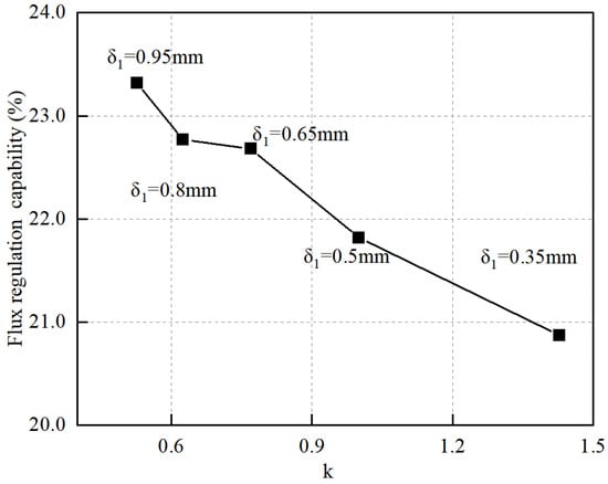
Figure 9.
Flux regulation capability with different radial air gap lengths.
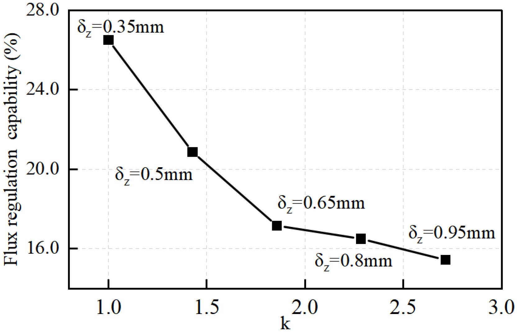
Figure 10 shows that the air gap length ratio increases with an increasing axial air gap length, but the flux regulation capability decreases from 26.51% to 15.44%. When is greater than 1, the axial air gap is larger than the radial air gap, and the flux regulation capability decreases significantly with the increasing axial air gap length.
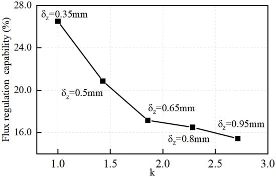
Figure 10.
Flux regulation capability with different axial air gap lengths.
The output torque consists of two parts: the main torque and the additional torque. The effect of the radial air gap length on the additional torque and output torque has also been studied, as shown in Figure 11. As the air gap length ratio decreases, the additional torque rises and the output torque decreases. Increasing the radial air gap from 0.35 mm to 0.95 mm results in the output torque decreasing by 31.05%. Simultaneously, this increase in the radial air gap also results in a 31.05% rise in additional torque. The increase in the radial air gap leads to an increase in the axial PM flux and the additional torque. The magnetic potential of the axial air gap has less effect on the main air gap flux because the bypass effect of the permanent magnets is weakened.
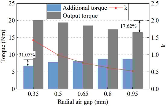
Figure 11.
Additional torque and output torque at different radial air gap lengths.
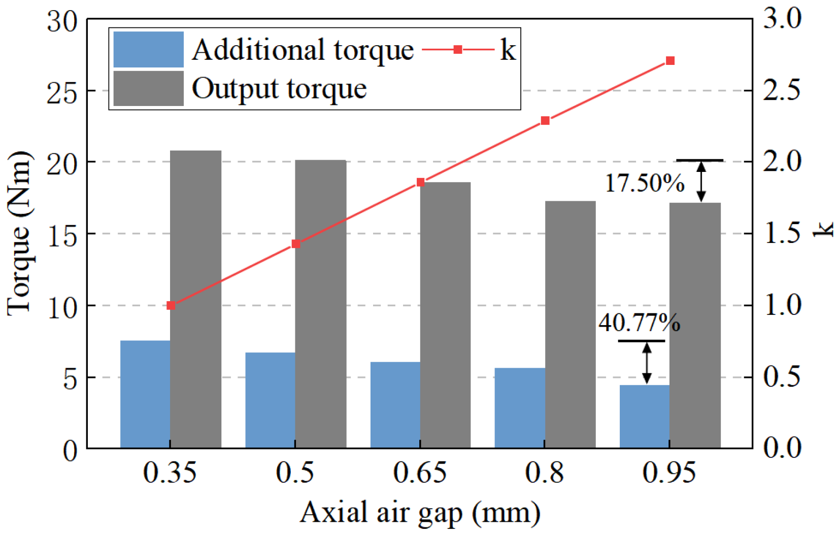
Figure 12 shows the variation of the additional torque and output torque at different axial air gap lengths. As the axial air gap length increases, the air gap length ratio increases, and the additional torque and the output torque decline. When the axial air gap length increases from 0.35 mm to 0.95 mm, the output torque decreases by 17.50%. Moreover, the increase in the axial air gap from 0.35 mm to 0.95 mm causes the additional torque to decrease by 40.77%, because the axial air gap length directly affects the axial air gap magnetic field.
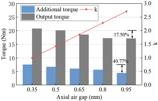
Figure 12.
Additional torque and output torque at different axial air gap lengths.
The dual air gaps of the machine have an effect on the magnetic field and the additional torque. The main aspects affected by different air gaps are different. The radial air gap length mainly affects the EMF and has less influence on the flux regulation.
4. Experimental Validation of the FTRHEM
An FTRHEM prototype was manufactured, according to the parameters in Table 3, for experimental validation of its performance. Figure 13 shows the experimental prototype. Figure 14 presents the test platform.
Table 3.
Design parameters.
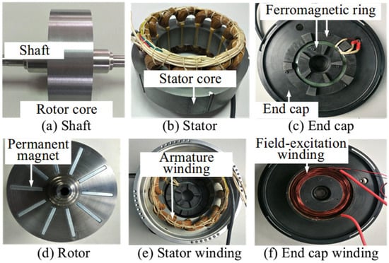
Figure 13.
Experimental prototype.
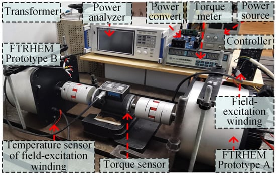
Figure 14.
Machine testing platform.
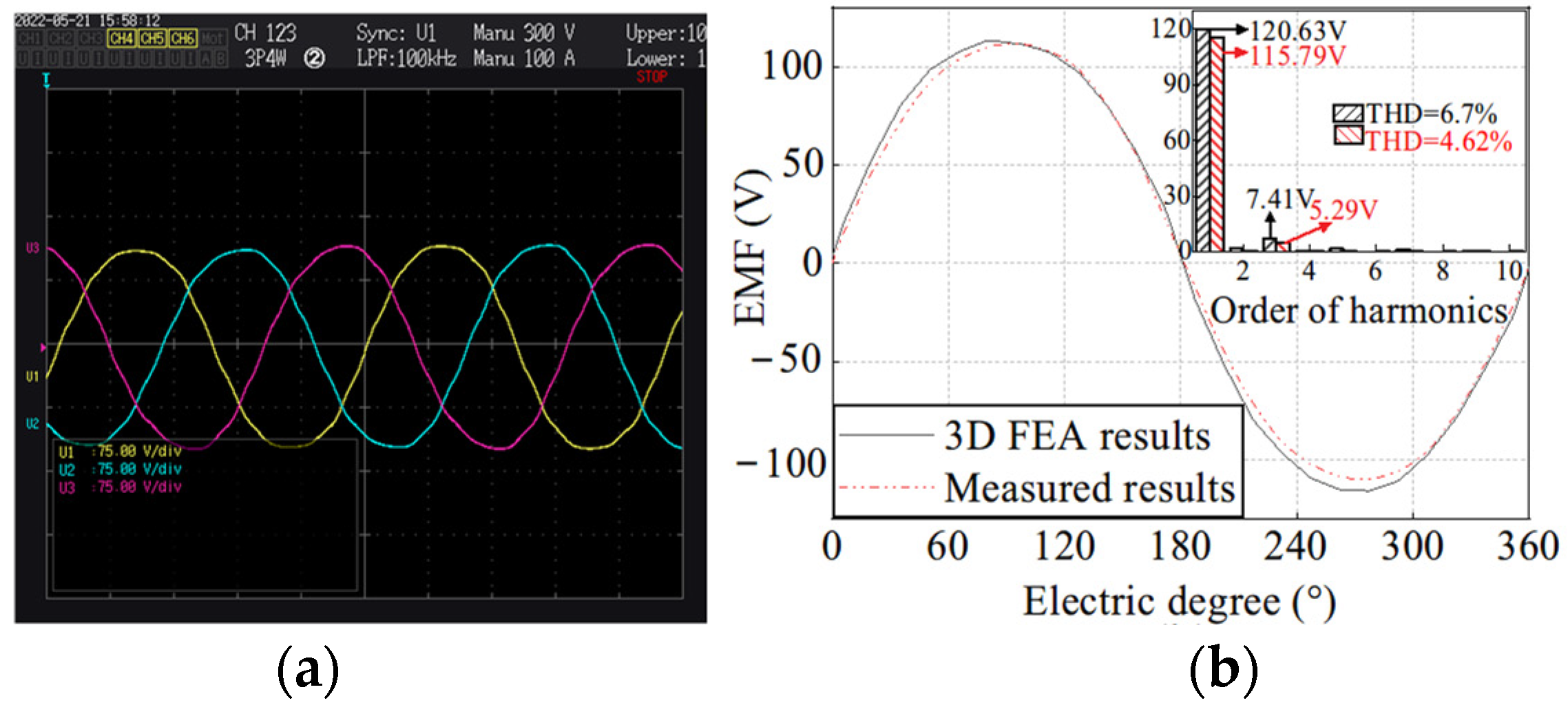
Figure 15 presents the EMF of the prototype at 250 r/min in the PM-only mode, as well as the harmonic analysis of the test results and the 3D FEA results. The fundamental amplitude of the EMF in the prototype experiment is 115.79 V, and the fundamental amplitude of the EMF in the FEA results is 120.63 V. The test results are consistent with the FEA results, indicating the high accuracy of the FEA model. The RMSV of the EMF of the prototype in different excitation currents is shown in Figure 16.
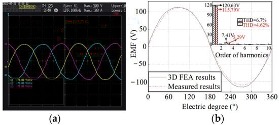
Figure 15.
EMF waveform in PM-only mode. (a) Measured waveforms. (b) Analysis of results.
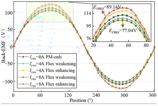
Figure 16.
The EMF of the prototype under different excitation currents.
As shown in Table 4, at an excitation current of 8 A, the flux regulation range is 15.78%, thus, the machine has very good flux regulation capability which can be adjusted by modifying the excitation current.
Table 4.
The no-load flux regulation range.
Table 5 shows the maximum instantaneous additional torque of the prototype, which indicates that the additional torque increases with changes in the excitation current. At an excitation current of 8 A, the additional torque reaches 6.87 Nm, thus, the FTRHEM can output a large amount of additional torque.
Table 5.
Instantaneous maximum electromagnetic torque.
5. Conclusions
In this paper, a novel FTRHEM that not only has good regulation performance, but also generates additional torque to increase the output torque is studied. Torque performance and magnetic regulation performance are important for FTRHEMs applied in electric vehicles. The equivalent magnetic network model was established to study the effect of dual air gaps on machine performance. The following conclusions can be drawn:
- The radial air gap and axial air gap of the FTRHEM have different effects on the magnetic field and the additional torque. The effect of the axial air gap on the flux regulation capability and additional torque is more significant than that of the radial air gap.
- As the radial air gap increases, the radial EMF decreases, the axial EMF increases, the flux regulation capability is enhanced, and the additional torque increases. When the radial air gap increases from 0.35 to 0.95 mm, the flux regulation capability decreases from 20.87% to 23.32%, and the additional torque increases by 31.05%.
- As the axial air gap increases, the radial EMF increases, the axial EMF decreases, the flux regulation capability decreases, and the additional torque increases. When the axial air gap increases from 0.35 mm to 0.95 mm, the flux regulation capability decreases from 26.51% to 15.44%, and the additional torque decreases by 40.77%.
- The air gap length ratio of the FTRHEM has a great influence on the machine’s flux regulation and additional torque performance. As the air gap length ratio decreases, the machine’s flux regulation capability increases, and the additional torque increases. After clarifying the effect of the air gap on the magnetizing capability as well as the additional torque capability, the performance of the FTRHEM can be further optimized.
Author Contributions
Conceptualization, H.Q. and C.Y.; methodology, Y.D.; validation, Y.Z. (Yifeng Zheng) and Y.D.; formal analysis, Y.Z. (Yuqing Zhang); investigation, C.Y.; resources, Y.Z. (Yuqing Zhang); writing—original draft preparation, C.Y.; writing—review and editing, Y.D.; supervision, H.Q.; funding acquisition, H.Q. All authors have read and agreed to the published version of the manuscript.
Funding
This research was funded by the Natural Science Foundation of China, under Grant 52077142; the National Natural Science Foundation of China, under Grant 52177063; the Excellent Young Scholars Project of Henan Province, under Grant 232300421070; the University Science and Technology Innovation Talent Support Program of Henan province, under Grant 23HASTIT026; and the Science and technology project of Henan Province, under Grant 232102220080, Grant 222102320074, and Grant 242102221002.
Data Availability Statement
The raw data supporting the conclusions of this article will be made available by the authors on request.
Conflicts of Interest
The authors declare no conflicts of interest.
References
- Zhu, Z.Q.; Howe, D. Electrical Machines and Drives for Electric, Hybrid, and Fuel Cell Vehicles. Proc. IEEE 2007, 95, 746–765. [Google Scholar] [CrossRef]
- Chau, K.T.; Chan, C.C.; Liu, C. Overview of Permanent-Magnet Brushless Drives for Electric and Hybrid Electric Vehicles. IEEE Trans. Ind. Electron. 2008, 55, 2246–2257. [Google Scholar] [CrossRef]
- Palka, R.; Cierzniewski, K.; Wardach, M.; Prajzendanc, P. Research on Innovative Hybrid Excited Synchronous Machine. Energies 2023, 16, 6600. [Google Scholar] [CrossRef]
- Wang, K.; Zhang, L. Integrated design of high-speed permanent-magnet machines considering sensor less operation. IEEE Trans. Electr. Electron. Eng. 2018, 13, 1931–4973. [Google Scholar] [CrossRef]
- Bai, H.; Yu, B. Position Estimation of Fault-Tolerant Permanent Magnet Motor in Electric Power Propulsion Ship System. IEEE Trans. Electr. Electron. Eng. 2022, 17, 890–898. [Google Scholar] [CrossRef]
- Zhang, Z.; Yan, Y.; Yang, S.; Bo, Z. Principle of Operation and Feature Investigation of a New Topology of Hybrid Excitation Synchronous Machine. IEEE Trans. Magn. 2008, 44, 2174–2180. [Google Scholar] [CrossRef]
- Qiu, H.; Yu, W.; Tang, B.; Mu, Y.; Li, W.; Yang, C. Study on the Influence of Different Rotor Structures on the Axial-Radial Flux Type Synchronous Machine. IEEE Trans. Ind. Electron. 2018, 65, 5406–5413. [Google Scholar] [CrossRef]
- Ayub, M.; Jawad, G.; Kwon, B. Consequent-pole hybrid excitation brushless wound field synchronous machine with fractional slot concentrated winding. IEEE Trans. Magn. 2019, 55, 8203805. [Google Scholar] [CrossRef]
- Zhang, G.; Song, N.; Zhou, G.; Zhu, M.; Guo, L.; Li, H. Based on the comparative analysis of the length of the air gap length of the finite element simulation permanent magnet synchronous motor. In Proceedings of the 2022 25th International Conference on Electrical Machines and Systems (ICEMS), Chiang Mai, Thailand, 29 November–2 December 2022; pp. 1–6. [Google Scholar] [CrossRef]
- Yung, C.; Griffith, J.T. The Effect of air gap on Electric Motor Performance: Copyright Material IEEE, Paper No. PCIC-2018-49. In Proceedings of the 2018 IEEE Petroleum and Chemical Industry Technical Conference (PCIC), Cincinnati, OH, USA, 24–26 September 2018; pp. 435–442. [Google Scholar] [CrossRef]
- Valtonen, M.; Parviainen, A.; Pyrhonen, J. Influence of the air-gap length to the performance of an axial-flux induction motor. In Proceedings of the 2008 18th International Conference on Electrical Machines, Vilamoura, Portugal, 6–9 September 2008; pp. 1–5. [Google Scholar] [CrossRef]
- Li, J.; Qu, R.; Cho, Y.-H. Effect of unbalanced and inclined air-gap in double-stator inner-rotor axial flux permanent magnet machine. In Proceedings of the 2014 International Conference on Electrical Machines (ICEM), Berlin, Germany, 2–5 September 2014; pp. 502–508. [Google Scholar] [CrossRef]
- Liu, C.; Si, J.; Zhang, W.; Li, Y.; Hu, Y. Electromagnetic Characteristics Analysis in Double-Sided Permanent Magnet Linear Synchronous Motor with Asymmetrical Air-Gap. IEEE Trans. Electr. Electron. Eng. 2022, 17, 1798–1810. [Google Scholar] [CrossRef]
- Zhang, Z.; Ma, S.; Dai, J.; Yan, Y. Investigation of Hybrid Excitation Synchronous Machines with Axial Auxiliary Air-Gaps and Non-Uniform Air-Gaps. IEEE Trans. Ind. Appl. 2014, 50, 1729–1737. [Google Scholar] [CrossRef]
- Qiu, H.; Yuan, C.; Chen, W.; Ma, X.; Xiong, B. Combined Regulation Performance Research of the Novel Flux-Torque Regulation Hybrid Excitation Machine with Axial-Radial Magnetic Circuit. IEEE Trans. Transp. Electrif. 2024. [Google Scholar] [CrossRef]
- Qiu, H.; Zhang, Y.; Ma, X.; Yang, C. Operating principle and performance analysis of a novel flux–torque regulation hybrid excitation machine with axial–radial magnetic circuit using magnetic network. IET Electr. Power Appl. 2023, 17, 824–834. [Google Scholar] [CrossRef]


Disclaimer/Publisher’s Note: The statements, opinions and data contained in all publications are solely those of the individual author(s) and contributor(s) and not of MDPI and/or the editor(s). MDPI and/or the editor(s) disclaim responsibility for any injury to people or property resulting from any ideas, methods, instructions or products referred to in the content. |
© 2024 by the authors. Published by MDPI on behalf of the World Electric Vehicle Association. Licensee MDPI, Basel, Switzerland. This article is an open access article distributed under the terms and conditions of the Creative Commons Attribution (CC BY) license (https://creativecommons.org/licenses/by/4.0/).