Article

Developing a Unified Framework for PMSM Speed Regulation: Active Disturbance Rejection Control via Generalized PI Control

1
School of Electrical and Electronic Engineering, Nanyang Technological University, 50 Nanyang Avenue, Singapore 639798, Singapore
2
College of Automation Engineering, Nanjing University of Aeronautics and Astronautics, Nanjing 211106, China
*
Author to whom correspondence should be addressed.
World Electr. Veh. J. 2025, 16(4), 193; https://doi.org/10.3390/wevj16040193
Submission received: 6 February 2025 / Revised: 20 March 2025 / Accepted: 24 March 2025 / Published: 26 March 2025

Abstract

:
With the growing demand for advanced control algorithms in permanent magnet synchronous motor (PMSM) speed regulation, active disturbance rejection control (ADRC) has garnered significant attention for its simplicity and effectiveness as an alternative to traditional proportional-integral (PI) controllers. However, two key challenges limit its broader application: the lack of an intuitive equivalence analysis that highlights the advantages of ADRC over PI control and the complexity in selecting appropriate extended state observer (ESO) structures within ADRC. To address these issues, this paper develops an equivalent model of ADRC based on the structure of a generalized PI controller, offering a clearer understanding of its operational principles. The results demonstrate the relationship between ADRC and generalized PI control while highlighting ADRC’s superior capabilities. Additionally, this paper constructs a generalized model that incorporates all ADRC observer configurations, including both high-order ESO (HESO) and cascaded ESO (CESO), enabling a comprehensive analysis of ADRC with various observer structures and establishing equivalence relationships between them. The findings provide valuable insights into the efficacy and versatility of ADRC in PMSM speed regulation, supported by experimental validation on a test bench using the dSPACE DS1202 MicroLabBox.

1. Introduction

Due to its high torque density and low maintenance requirements, permanent magnet synchronous motor (PMSM) has become widely adopted in various industrial applications [1,2]. Initially, the speed regulation of PMSM was achieved using proportional-integral (PI) controllers within the field-oriented control (FOC) framework [3]. However, PI controllers exhibit inherent limitations, particularly in their inability to simultaneously optimize the tracking performance and disturbance rejection [4]. To overcome these shortcomings, the generalized proportional-integral-derivative (PID) controller was introduced [5], providing additional degrees of freedom (DOF) that allow for the improved tuning of the transient response speed and noise attenuation. Despite these advancements, the inclusion of a low-pass filter (LPF) to mitigate noise amplification caused by the derivative term introduces increased complexity in parameter tuning, while the integral term remains susceptible to saturation, potentially leading to overshoot and instability under certain operating conditions [6].
These challenges can be addressed by active disturbance rejection control (ADRC), which has been attracting a great amount of interest from both the academic and industrial communities due to its simplicity as an alternative to classic PI controllers [7]. It was initially proposed by Han [8] and further simplified by Gao [9] as linear ADRC with its control gain tuning procedure only setting up the bandwidth of the observer. The core of ADRC is to replace the integral term in the PI controller with an extended state observer (ESO), which is able to estimate a lumped disturbance term encompassing both external disturbances and internal disturbances arising from parameter variations or unmodeled dynamics [10]. Hence, the ESO enables ADRC to offer a unified approach addressing both linear and nonlinear systems [11]. Consequently, the ESO plays a pivotal role in the ADRC system.
As a critical component of ADRC, significant attention has been devoted to enhancing system performance through observer reconstruction, including the high-order ESO (HESO) and cascaded ESO (CESO). For instance, two second-order ESOs were cascaded in [12] to enhance disturbance rejection by enabling the first ESO to estimate part of the disturbance, thereby reducing the response time for the subsequent ESO. Similarly, a fourth-order ESO was introduced in [13] to further improve disturbance rejection. Beyond this, CESOs have also been utilized for noise suppression, with studies such as [14,15] demonstrating that CESOs can achieve superior noise suppression, while [16] highlights HESOs as a viable alternative with similar benefits.
The previously discussed studies suggest potential equivalence between the HESO and CESO, which has been partially supported by various investigations. In [17], a three-level CESO was transformed to a two-level configuration, while, in [18], a fourth-order ESO was simplified into several second-order ESOs arranged in cascade. More recently, in [19], the equivalence between a CESO consisting of two second-order ESOs and a fourth-order ESO was demonstrated, with both structures showing accordant performance improvements. However, the general and precise relationship between the HESO and CESO remains unclear, highlighting the need for further research to fully understand their roles and interactions.
Furthermore, given that the PID control algorithm holds the highest impact rating in industrial applications [20], formulating a unified expression of ADRC in the form of a generalized PI controller could provide deeper insights into ADRC and foster its broader adoption. Significant efforts have been made in this direction. For instance, in [21,22], ADRC for speed regulation using a second-order ESO was reformulated as a PI controller. Building on this foundation, Ref. [23] extended the analysis to higher-order ADRC, incorporating both the mechanical and electrical models of a PMSM. Additionally, Ref. [24] explored ESO configurations, including the HESO and CESO. However, these existing studies have primarily focused on theoretical derivations and often neglect the physical interpretation of each component in the equivalent transformation process.
To enable a more comprehensive analysis of ADRC, this paper develops an equivalent model of ADRC based on the structure of a generalized PI controller, providing a clear perspective on its operational principles. The results intuitively demonstrate the relationship between ADRC and generalized PI control while highlighting the superior capabilities of ADRC. Furthermore, considering the diverse observer designs in ADRC, including the HESO and CESO, this study constructs a generalized model encompassing all observer configurations. This generalized model enables the comprehensive analysis of ADRC with different observer configurations and establishes equivalence relationships between them. In conclusion, the originality of this paper lies in the following contributions.
  • This paper refines the equivalent transformation of ADRC to ensure that each component in the equivalent model retains a clear physical interpretation, thereby enhancing the intuitive understanding of ADRC.
  • This paper systematically examines and establishes the equivalence relationships between the HESO and CESO. By providing a clear correspondence between these observer structures, the findings offer deeper insights into the role of observers within ADRC.
The remainder of the paper is structured as follows. Section 2 models the complete ADRC speed regulation system and transforms it into an equivalent generalized PI form for better understanding, while also detailing the observer design and proposing a unified framework incorporating both the HESO and CESO. Section 3 provides a frequency-domain analysis comparing ADRC with generalized PI control and exploring the equivalent relationship of ADRC with different observer configurations. Section 4 validates the frequency-domain findings through experimental results, and Section 5 concludes the study by summarizing the key insights and contributions.

2. System Modeling

This section first provides a detailed modeling procedure for the complete ADRC speed regulation system. It then thoroughly transforms the model into an equivalent generalized PI form for better clarity and understanding. Finally, this section outlines the observer design and introduces a unified framework that incorporates both the HESO and CESO.

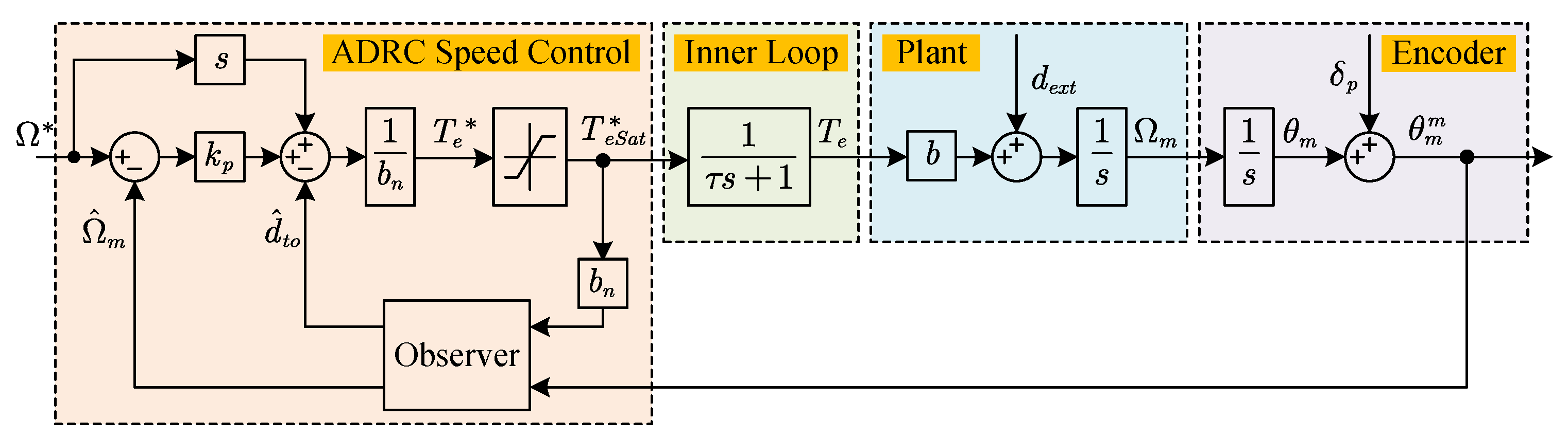
2.1. ADRC Speed Regulation System Construction

This subsection provides a detailed description of the ADRC’s construction, including both the physical and control components, covering motor modeling and the ADRC control strategy. They are introduced as follows.

2.1.1. Physical System Modeling

The mechanical model of PMSM is governed by Newton’s second law of motion, which is
ω ˙ m = B ω m + T e T L J = b T e + d e x t
where ω m is the rotor angular speed, B is viscous damping, T e is the electrical torque, T L is the load torque, J is rotor inertia, and, to simplify the expression, coefficient b is defined as b = 1 / J , and d e x t = b B ω m T L is the external disturbance.
From (1), the PMSM mechanical model can be obtained in the form of a transfer function in the frequency domain as
G s = Ω m b T e + d e x t = 1 s
where Ω m is the expression of ω m in the frequency domain.
However, the rotor inertia and electric torque cannot be obtained directly. Hence, these two variables are replaced with nominal rotor inertia J n and torque reference T e . Thus, (1) becomes
ω ˙ m = b n T e + d t o
where b n = 1 / J n , d t o = d n ( b n b ) T e is the total disturbance.
Since this paper focuses on PMSM speed regulation, the inner torque control loop is simplified as a first-order inertia process:
D s = T e T e = 1 τ s + 1
where τ is the time constant of the inner loop.
Another physical part that needs to be considered is the encoder measuring process:
θ m m = Ω m s + δ p
where θ m m is the measured position from the encoder and δ p is the measurement noise.

2.1.2. ADRC Control Strategy

The tracking error of the rotor mechanical speed can be expressed as
e s = ω m ω m
where ω m is the speed reference. By taking its derivative and substituting it into (3), it can be obtained that
e ˙ s = ω ˙ m b n T e + d t o
Then, we design the desired tracking error convergence law in a simple proportional control with gain k p as
e ˙ s = k p e s
Substituting (8) into (7) yields
T e = ω ˙ m + k p ω m ω m d t o b n
Using the estimated states, including the estimated rotor angular speed Ω ^ m and estimated total disturbance d ^ t o , the torque reference is modified in the frequency domain as
T e = s Ω m + k p Ω m Ω ^ m d ^ t o b n
where Ω m is the expression of ω m in the frequency domain.
Combining physical system modeling, the complete system can finally be constructed, as illustrated in Figure 1.

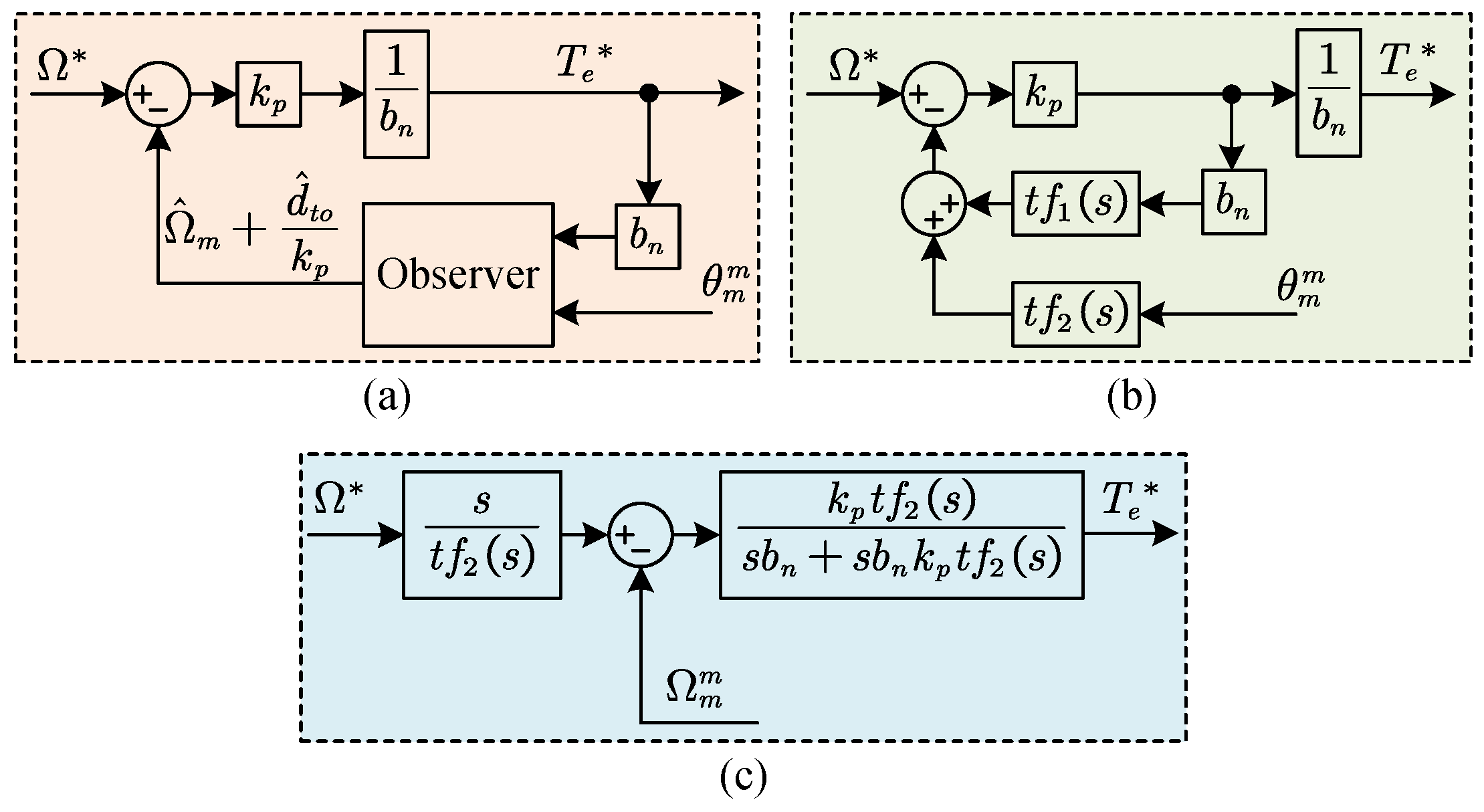
2.2. Equivalent Model Construction

Since the derivative of the speed reference is only significant during moments of change, it can be disregarded for most of the time. Additionally, for the sake of simplifying the analysis, the effects of saturation are also neglected. As a result, Figure 2a can be obtained as the first step of equivalent model transformation.
The second step, as shown in Figure 2b, combines the two outputs, and two immediate transfer functions t f 1 s and t f 2 s are constructed to represent their relationships with the two inputs as
Ω ^ m + d ^ t o k p = t f 1 s b n T e + t f 2 s θ m m
After simplification, Figure 2c can be obtained. Moreover, by defining
H s = s t f 2 s C s = k p t f 2 s s b n + s b n k p t f 1 s
the ADRC system can be simplified as a speed unit feedback control system, which is shown in Figure 3a, where Ω m m is the measured speed containing speed measurement noise: δ s = s δ p .

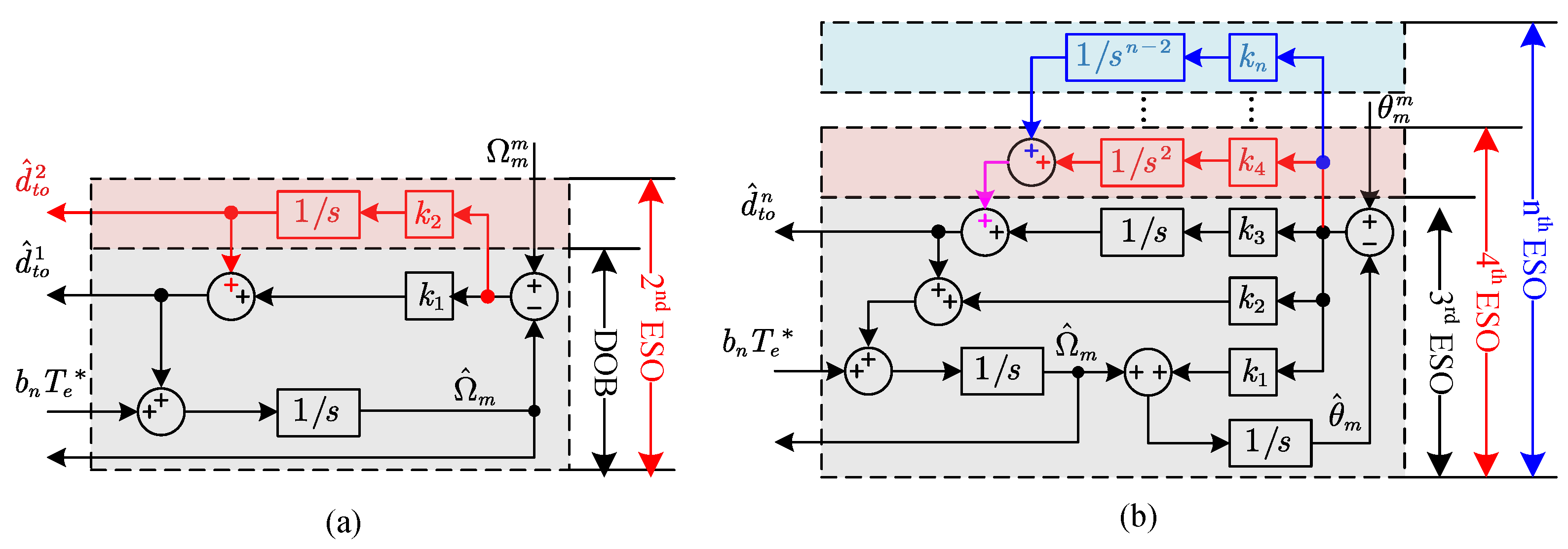
2.3. Observer Construction

Considering the motor’s mechanical model as a first-order system, as represented in (2), a first-order ESO, also known as a disturbance observer (DOB), and a second-order ESO can be constructed to estimate both the speed and disturbance, as illustrated in Figure 4a.
When (2) is extended to account for the position angle as the integral of mechanical speed, the system is modeled as a second-order system. Under this configuration, third-order and higher-order ESOs can be designed to estimate the speed, position angle, and disturbance, as illustrated in Figure 4b.
All of these various ESO configurations, ranging from first order to nth order, along with their corresponding transfer functions and gain settings, are provided in Table 1, where Ω ˜ m is the speed estimation error, θ ˜ m is the position estimation error between θ m m and estimated position θ ^ m , and ω o is the bandwidth of the observer.
Within the same order of ESOs, the estimated disturbance and speed can vary depending on the chosen configuration of its branches, and these different ESO configurations are collectively referred to as the generalized PI observer (GPIO). To generalize this expression, G 1 ( s ) and G 2 ( s ) are employed to represent different GPIOs of the same order. Based on the rules summarized in Table 1, the generalized expression of an nth-order GPIO is obtained as (13).
θ ˜ m m = s n θ m m s n 2 b n T e s + ω o n Ω ^ m = s θ m m θ ˜ m m G 1 θ ˜ m m d ^ t o = G 2 θ ˜ m m
Hence, the block diagram of an nth-order GPIO is designed as in Figure 5.

3. Frequency-Domain Analysis

This section provides a frequency-domain analysis, where the ADRC system is compared with generalized PI control. It verifies the equivalence between ADRC and generalized PI control from a frequency response perspective. Additionally, this section explores the equivalence between different observer structures, establishing a clear correspondence rule. Detailed transfer functions and corresponding Bode plots are also provided to illustrate the analysis.

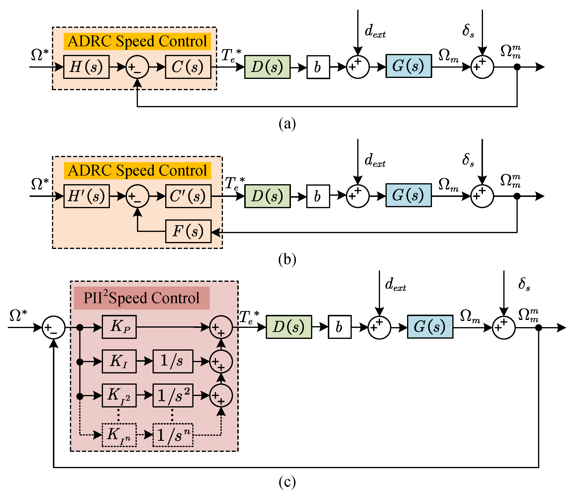
3.1. Analysis of the Equivalence of ADRC and Generalized PI Control

As illustrated in Figure 3a, H ( s ) and C ( s ) are pivotal in determining the performance of ADRC. Their expressions can be derived by substituting the transfer functions of different ESOs, as provided in Table 1, into (11) and (12). Their resulting expressions are listed in Table 2.
As shown in Table 2, for orders above the second, the numerator of H ( s ) exceeds its denominator, indicating that, while the mathematical equivalence is correct, it lacks physical significance. To address this issue, an LPF as F ( s ) is introduced in the modified structure shown in Figure 3b. Hence, H ( s ) and C ( s ) can be transformed into H ( s ) and C ( s ) by
H s = H s F s C s = C s F s
The transfer functions of F ( s ) are provided in Table 3, where ω c represents the cut-off frequency of the LPF and ζ is the damping ratio. By substituting F ( s ) into (14), the previously meaningless H ( s ) is transformed into a transient process, H ( s ) . This modification highlights that, in comparison with generalized PI control, ADRC inherently includes a transient process for the speed reference.
In addition, using (14), the revised C ( s ) with their parameters are obtained as in Table 4, where K P , K I and K I 2 represent the proportional, integral, and double integral control gains of the generalized PI controller.
From Table 3 and Table 4, it is evident that ADRC utilizing a DOB functions as a proportional (P) controller. When employing a second-order ESO, ADRC operates as a PI controller with a first-order LPF. Similarly, with a third-order ESO, ADRC functions as a PI controller with a second-order LPF. For a fourth-order ESO, ADRC adopts the structure of a PII2 controller with a second-order LPF. Consequently, it can be reasonably concluded that, for an nth-order ESO, ADRC assumes the role of a PII2 I ( n 2 ) controller with a second-order LPF.

3.2. Analysis of ADRC with HESO and CESO

The principle of a CESO is to link multiple ESOs in cascade, where the estimated speed from the preceding ESO serves as the actual speed input for the subsequent ESO. This relationship can be mathematically expressed with the assumption that there are n ESOs cascaded in a CESO as follows:
Ω ˜ m , 1 = Ω m m Ω ^ m , 1 Ω ˜ m , i = Ω ^ m , i 1 Ω ^ m , i i 1 , n
where Ω ˜ m , i and Ω ^ m , i are the input speed error and output estimated speed of the ith ESO among the n ESOs.
The output of a CESO includes the estimated speed from the final ESO and the estimated disturbance, which is the summation of the disturbances estimated by all individual ESOs:
Ω ^ m = Ω ^ m , n d ^ t o = Σ d ^ t o , i i 1 , n
where d ^ t o , i is the estimated total disturbance of the ith ESO among n ESOs.
To find the relationship between the CESO and HESO, four examples of two layered CESOs are introduced in Figure 6. They are named CESOij, where i j stands for the order of ESO used in the first and second layer, respectively.
Figure 6a illustrates the cases of CESO11 and CESO12, where CESO11 represents a DOB cascaded with another DOB, and CESO12 represents a DOB cascaded with a second-order ESO. From Figure 6a, if the bandwidth of each observer is set uniformly to ω o , their outputs can be calculated equally as
Ω ^ m = s θ m m s 2 θ m m b n T e s + ω o d ^ t o = k 1 s 2 θ m m k 1 b n T e s + ω o
From (17), it is evident that the outputs of CESO11 and CESO12 are identical to that of a DOB. This observation reveals a key principle: if the first observer in a CESO is a DOB, the overall CESO functions equivalently to a DOB, regardless of the type of observer that follows.
Subsequently, Figure 6b replaces the first observer with a second-order ESO, presenting the cases of CESO21 and CESO22. With the same bandwidth configuration, the output of CESO21 can be expressed as
Ω ^ m = s θ m m s s 2 θ m m b n T e s + ω o 2 2 ω o s s 2 θ m m b n T e s + ω o 3 d ^ t o = ω o 2 s 2 θ m m b n T e 3 s + ω o s + ω o 3
From (18), it can be observed that the denominator is cubic. Hence, substituting (18) into (13) with n = 4 yields
G 1 s = 3 ω o G 2 s = 3 ω o 2 + ω o 3 s
This shows that CESO21 is equivalent to a third-order GPIO, with G 1 ( s ) and G 1 ( s ) set according to (19).
Similarly, the output of CESO22 can be obtained as
Ω ^ m = s θ m m s 3 θ m m s b n T e s + ω o 2 2 ω o s 2 s 2 θ m m b n T e s + ω o 4 d ^ t o = ω o 2 s 2 θ m m b n T e s 2 + 4 ω o s + ω o 2 s + ω o 4
Since the demoninator of (20) has a power of four, substituting (20) into (13) with n = 4 yields
G 1 s = 4 ω o + ω o 2 s G 2 s = ω o 2 + 4 ω o 3 s + ω o 4 s 2
This shows that CESO22 is equivalent to a fourth-order GPIO, with G 1 ( s ) and G 2 ( s ) set according to (21).
From the above derivations, it can be concluded that each CESO has an equivalent GPIO. Specifically, the equivalence rule is as follows: when the first observer in the CESO is a first-order DOB, the CESO is equivalent to a DOB regardless of the order of the subsequent observers. In all other cases, the CESO is equivalent to a GPIO, with its order being the sum of the orders of all individual ESOs in the cascade.

3.3. System Performance Analysis

Based on Figure 3b, system closed-loop transfer functions of the motor mechanical speed relating to the speed reference, speed measurement noise and external disturbance can be obtained as
Ω m Ω m = b H s C s D s G s 1 + b C s D s G s F s Ω m δ s = b C s D s G s F s 1 + b C s D s G s F s Ω m d e x t = G s 1 + b C s D s G s F s
By substituting the transfer functions shown in (2) and (4) and Table 3 and Table 4 into (22), several Bode plots are obtained, as presented below, to illustrate the system’s performance through frequency-domain analysis.

3.3.1. Comparative Analysis of ADRC and Generalized PI Control

With the control gains of ADRC set as k p = ω o = 200 π rad/s, the bandwidth of PI control is set as ω C = 200 π rad/s, while its control gain can be calculated from K P = 2 ω C / b n , K I = ω C 2 / b n . The Bode plots of PI and ADRC with second- and third-order ESOs are shown in Figure 7.
Figure 7a illustrates that the second-order ESO and third-order ESO act as PI controllers, achieving a disturbance rejection slope of 20 dB/dec. Moreover, the second-order ESO introduces a first-order LPF, while the third-order ESO incorporates a second-order LPF in the speed feedback loop. As shown in Figure 7b, this enhancement significantly improves the noise suppression, increasing the attenuation rate from −40 dB/dec to −60 dB/dec and −80 dB/dec, respectively.
As a two-DOF controller, ADRC typically sets the proportional gain k p smaller than the observer bandwidth ω o . To examine the effect of a reduced k p , it is changed to 20 π rad/s, while retaining ω o = 200 π rad/s. Figure 8 presents the Bode plot comparisons between the PI controller and ADRC with the reduced k p .
Comparing Figure 8 with Figure 7, it can be seen that, upon reducing k p , the tracking performance deteriorates significantly, while disturbance rejection and noise suppression are less affected. Additionally, the characteristic of PI control with an LPF on the feedback loop remains evident.
Subsequently, a similar comparative study is conducted between the PII2 controller and ADRC with a fourth-order ESO. The observer bandwidth for the ESO and the control bandwidth for the PII2 controller are set to the same values as before, which are ω o = ω C = 200 π rad/s. The control gains for the PII2 controller are calculated as follows: K P = 3 ω C / b n , K I = 3 ω C 2 / b n , and K I 2 = ω C 3 / b n . The Bode plots are illustrated in Figure 9, where the green line represents the fourth-order ESO with k p = 200 π rad/s, and the blue line represents the same fourth-order ESO with a reduced k p = 20 π rad/s.
Figure 9 proves that ADRC with a fourth-order ESO is equivalent to a PII2 controller in disturbance rejection at the slope of 40 dB/dec. Meanwhile, it improves the noise suppression by introducing a second-order LPF, resulting in the slope decreasing from −40 dB/dec to −80 dB/dec.

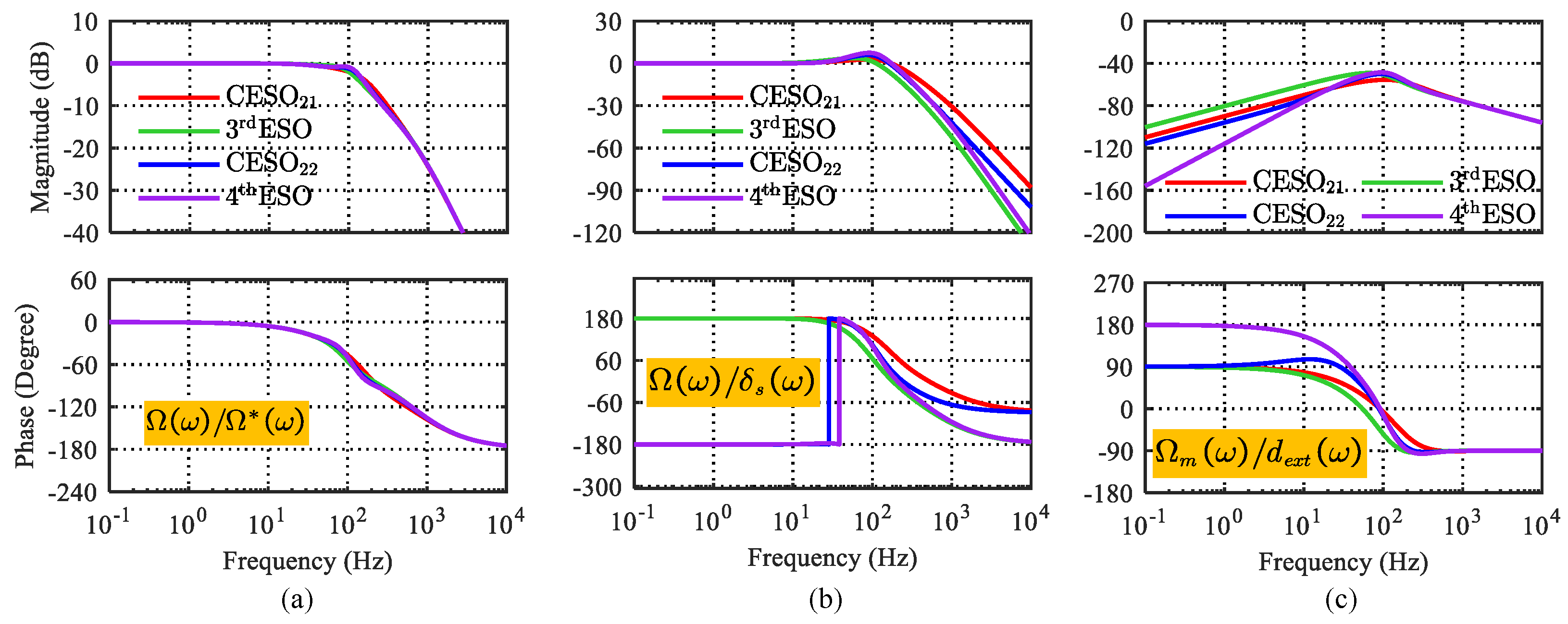
3.3.2. Comparative Analysis of CESO and HESO

Although the equivalence between the CESO and GPIO has been established in the preceding derivation, their performance has not yet been compared. Based on the previous deduction, CESO21 is equivalent to a third-order GPIO, while CESO22 corresponds to a fourth-order GPIO. To evaluate their performance, these two types of CESOs are compared with classical third- and fourth-order ESOs, as listed in Table 1. The Bode plots illustrating their performance are shown in Figure 10.
From Figure 10, it can be observed that, compared to the classical third-order ESO, CESO21 exhibits similar disturbance rejection characteristics but demonstrates poorer noise suppression performance. Similarly, compared to the classical fourth-order ESO, CESO22 shows comparable noise suppression capabilities but exhibits inferior disturbance rejection performance.
Thus, it can be concluded that, while cascading ESOs extends their equivalent order to the sum of each individual ESO’s order, the overall performance is not consistently improved or guaranteed when compared to the original ESO of the same order.

4. Experimental Results

This section presents the experiments, including an introduction to the test bench and the experimental results comparing the performance of ADRC with generalized PI control, as well as the evaluation of ADRC utilizing different observer structures. The experiments encompass the key findings derived from the frequency-domain analysis from the previous section, thereby providing additional validation in the time domain. A medium speed of 500 r/min is selected for the demonstration to illustrate the general applicability of the findings across the whole speed range.

4.1. Test Bench Setup

To validate the findings from the frequency-domain analysis, experiments were conducted using a test bench equipped with dual-drive PMSMs, as illustrated in Figure 11.
The parameters of the test PMSM are listed in Table 5.

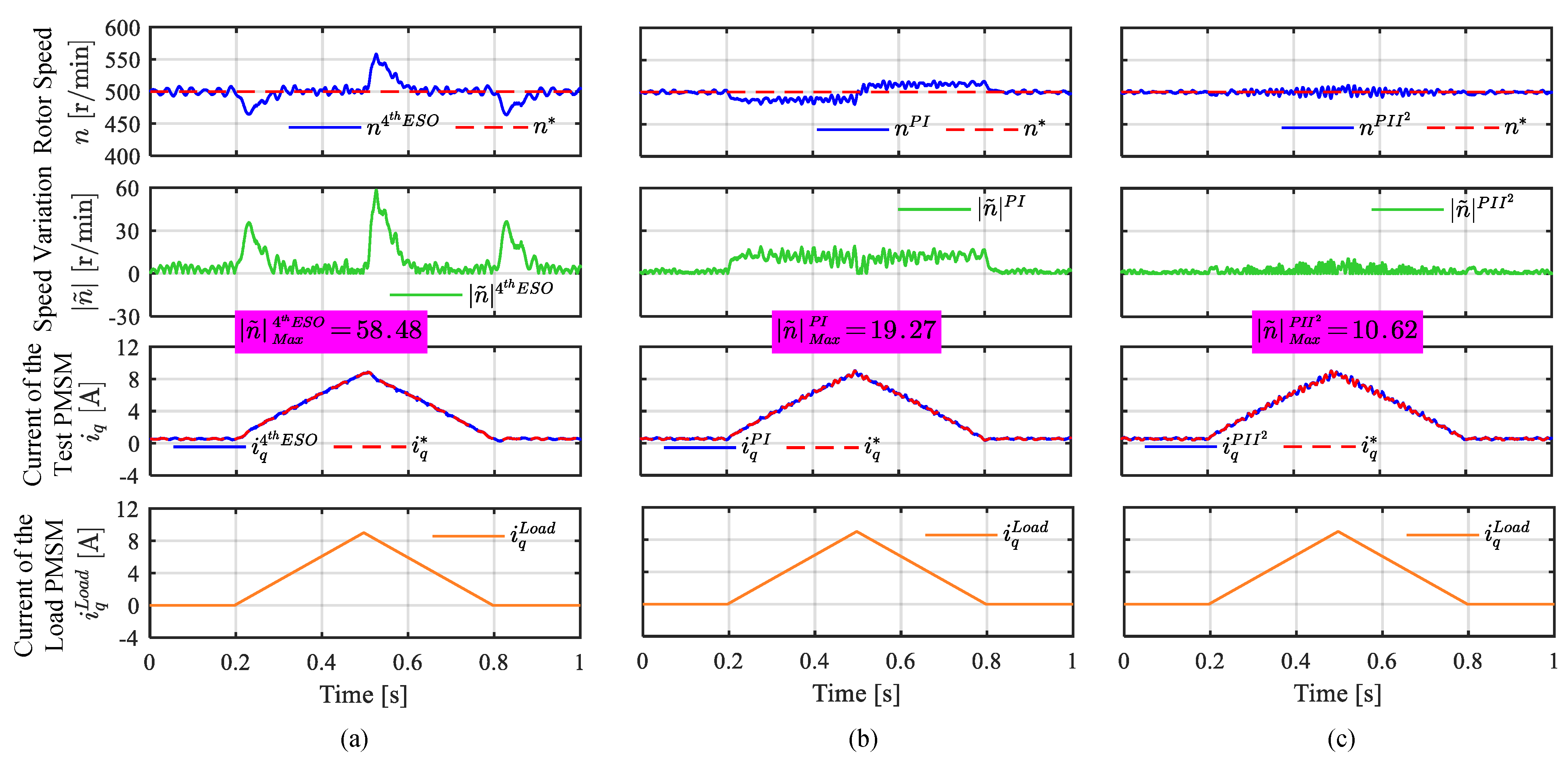
4.2. Comparative Experiments on ADRC and Generalized PI Controller

The first experiment aims to verify the accuracy of the Bode plot in Figure 8. In this scenario, the control gains for ADRC are set as k p = 20 π rad/s and ω o = 40 π rad/s. For the PI controller, the control gain is configured as ω C = 40 π rad/s. The PMSM operates at 500 r/min, with a step load of 1 A applied to the load motor at t = 0.2 s and removed at t = 0.8 s. The resulting speed response is depicted in Figure 12.
From Figure 12, it can be observed that all controllers exhibit no steady-state error in speed when subjected to a constant external disturbance, confirming the 20 dB/dec slope shown in Figure 8c. Furthermore, the speed variation of the PI controller is smaller than that of ADRC with a second-order ESO and smaller than ADRC with a third-order ESO. This behavior aligns with the relative positions of the three Bode plot curves in Figure 8c.
The second experiment extends the analysis to include a fourth-order ESO and PII2 control, with the control gain settings kept consistent with those in the first experiment. A ramp load with a slope of 3 A/s is applied at t = 0.2 s and removed with a slope of −3 A/s at t = 0.5 s. The resulting speed response is recorded in Figure 13.
From Figure 13, it can be observed that ADRC with a fourth-order ESO and the PII2 controller effectively eliminate the steady-state error when encountering a first-order external disturbance, thereby verifying the 40 dB/dec slope depicted in Figure 9c. Additionally, since the Bode curve of the PII2 controller exhibits a lower amplitude compared to ADRC with a fourth-order ESO, its speed variation is shown to be smaller in Figure 13.

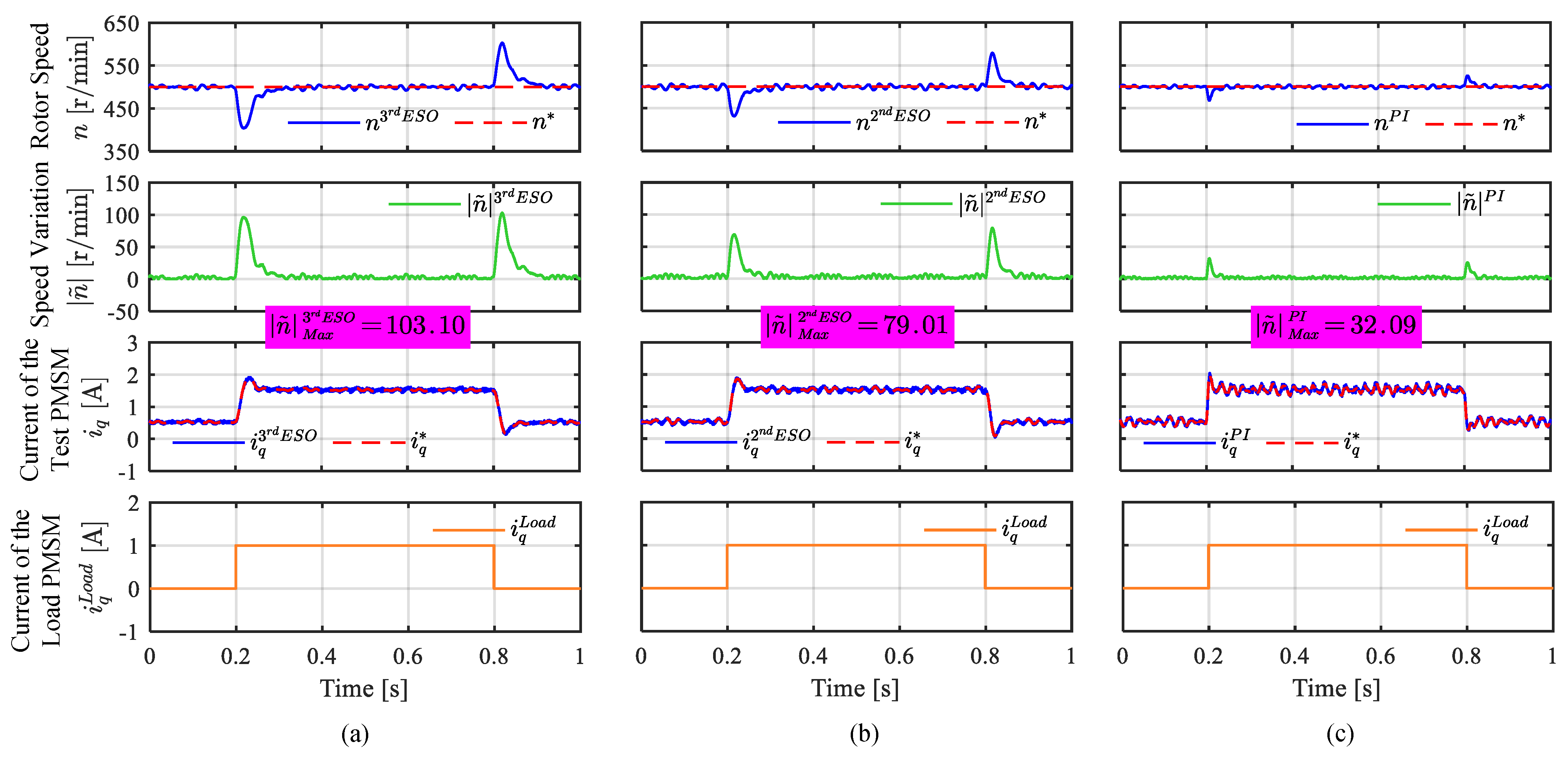
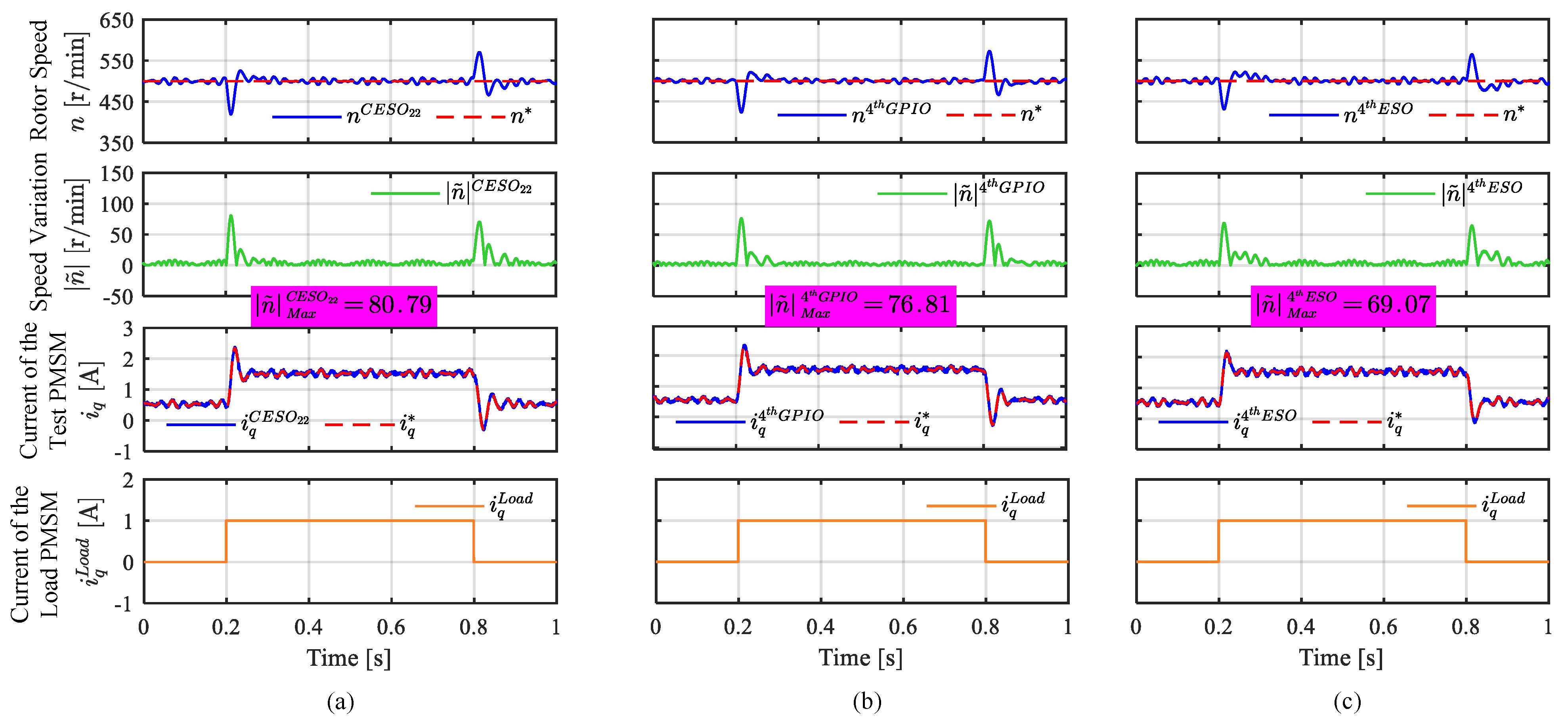
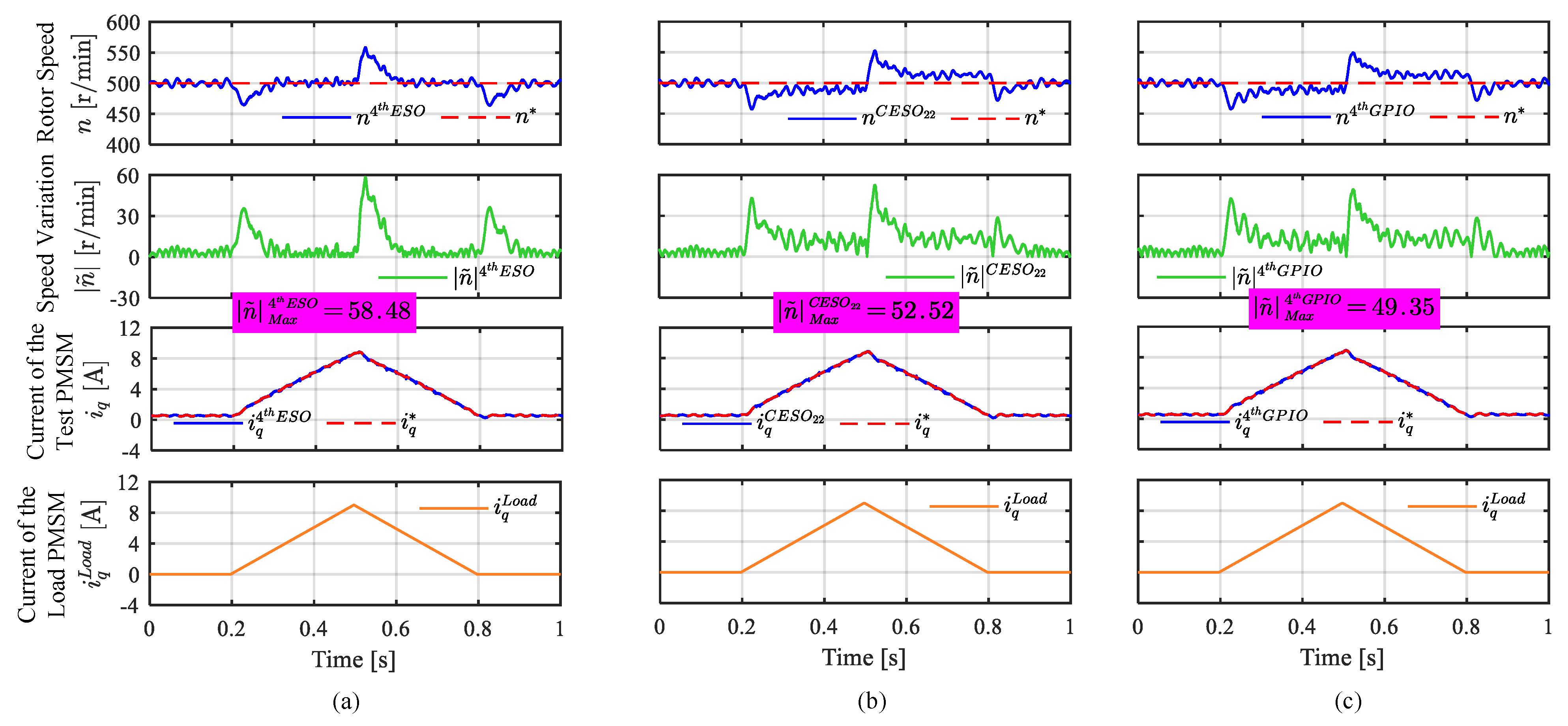
4.3. Comparative Experiments on ADRC with Different Observer Structures

The third experiment validates the equivalence of CESO with GPIO and compares their performance against a traditional fourth-order ESO. CESO22, its equivalent GPIO, and a fourth-order ESO are tested with identical control gains ( k p = 20 π rad/s, ω o = 40 π rad/s). System responses to step and ramp disturbances are shown in Figure 14 and Figure 15.
From Figure 14 and Figure 15, it can be observed that, under both step and ramp load conditions, the speed variations of ADRC using CESO22 and the fourth-order GPIO are similar, and both exhibit steady-state errors during ramp loads, thereby validating their equivalence. In contrast, ADRC employing the fourth-order ESO shows fewer speed variations during the step load change and effectively eliminates the steady-state error during the ramp load change, demonstrating superior disturbance rejection capabilities. This phenomenon aligns with the frequency-domain analysis presented in Figure 10.

5. Conclusions

This paper presents a unified framework that integrates ADRC and generalized PI controllers for PMSM speed regulation, emphasizing the key advantages of ADRC over PI control. Notably, ADRC offers inherent enhancements, such as a built-in transient response mechanism for speed reference tracking and the inclusion of an LPF in the speed feedback loop. Additionally, this work introduces a unified observer framework that encompasses both the HESO and CESO, clarifying the equivalence between them. Specifically, it is shown that, when the initial observer in a CESO is of the first order, the entire CESO behaves as a first-order ESO, regardless of the configurations of subsequent observers. In contrast, when the initial observer is of the second order or higher, the overall order of the CESO corresponds to the sum of the individual observers’ orders.
Beyond its theoretical contributions, this paper has important practical implications for PMSM speed regulation. The proposed framework offers a systematic methodology for the tuning and implementation of ADRC-based controllers, thereby facilitating their application in industrial motor control systems. Furthermore, by elucidating the structural relationships between different observer designs, this paper improves the efficiency of control system design, reducing redundancy in observer reconstruction.

Author Contributions

Conceptualization, H.W., Y.Z. and C.Z.; methodology, H.W. and Y.Z.; software, H.W. and C.Z.; validation, H.W., Y.Z. and C.Z.; formal analysis, H.W. and Y.Z.; investigation, H.W. and C.Z.; writing—original draft preparation, H.W. and Y.Z.; writing—review and editing, H.W., Y.Z., C.Z. and C.H.T.L.; supervision, C.H.T.L.; funding acquisition, C.H.T.L. All authors have read and agreed to the published version of the manuscript.

Funding

This research was funded by the National Research Foundation (NRF) of Singapore under NRF Fellowship Grant NRF-NRFF12-2020-0003.

Institutional Review Board Statement

Not applicable.

Informed Consent Statement

Not applicable.

Data Availability Statement

The original contributions presented in this study are included in the article. Further inquiries can be directed to the corresponding author.

Conflicts of Interest

The authors declare no conflicts of interest.

Nomenclature

bReciprocal of the actual rotor inertia b n Reciprocal of the nominal rotor inertia
BViscous damping d e x t External disturbance
d t o Total disturbance d ^ t o Estimated total disturbance
d ^ t o , i Estimated total disturbance of the ith ESO e s Speed tracking error
JActual rotor inertia J n Nominal rotor inertia
K I Integral control gain of the generalized PI controller K I 2 Double integral control gain of the generalized PI controller
k p Proportional control gain of ADRC K P Proportional control gain of the generalized PI controller
L d d-axis inductance L q q-axis inductance
n N Rated speed p n Pole pair number
P N Rated power R s Stator resistance
T e Electric torque T e Torque reference
T L Load torque T N Rated torque
V N Rated voltage δ p Position measurement noise
δ s Speed measurement noise ψ f Rotor flux
τ Time constant of the inner loop θ m m Measured position from the encoder
θ ^ m Estimated position θ ˜ m Position estimation error
ω c Cut-off frequency of the LPF ω C Bandwidth of the generalized PI controller
ω m Rotor angular speed ω m Rotor angular speed reference
ω o Bandwidth of the observer Ω m Rotor angular speed in the frequency domain
Ω m m Measured rotor angular speed Ω ^ m Estimated rotor angular speed
Ω m Rotor angular speed reference in the frequency domain Ω ˜ m Speed estimation error
Ω ˜ m , i Input speed error of the ith ESO Ω ^ m , i Estimated speed of the ith ESO
ζ Damping ratio of the LPF

References

  1. Fang, S.; Wang, Y.; Wang, W.; Chen, Y.; Chen, Y. Design of permanent magnet synchronous motor servo system based on improved particle swarm optimization. IEEE Trans. Power Electron. 2021, 37, 5833–5846. [Google Scholar] [CrossRef]
  2. Cao, D.; Zhao, W.; Ji, J.; Wang, Y. Parametric equivalent magnetic network modeling approach for multiobjective optimization of PM machine. IEEE Trans. Ind. Electron. 2020, 68, 6619–6629. [Google Scholar] [CrossRef]
  3. Song, W.; Li, J.; Ma, C.; Xia, Y.; Yu, B. A simple tuning method of PI regulators in FOC for PMSM drives based on deadbeat predictive conception. IEEE Transp. Electrif. 2024, 10, 9852–9863. [Google Scholar]
  4. Hori, Y. Disturbance suppression on an acceleration control type DC servo system. In Proceedings of the PESC ’88 Record, 19th Annual IEEE Power Electronics Specialists Conference, Kyoto, Japan, 11–14 April 1988; pp. 222–229. [Google Scholar]
  5. Huba, M.; Vrancic, D.; Bistak, P. PID control with higher order derivative degrees for IPDT plant models. IEEE Access 2020, 9, 2478–2495. [Google Scholar] [CrossRef]
  6. Espina, J.; Arias, A.; Balcells, J.; Ortega, C. Speed anti-windup PI strategies review for field oriented control of permanent magnet synchronous machines. In Proceedings of the 2009 Compatibility and Power Electronics, Badajoz, Spain, 20–22 May 2009; pp. 279–285. [Google Scholar]
  7. Chen, W.-H.; Yang, J.; Guo, L.; Li, S. Disturbance-observer-based control and related methods—An overview. IEEE Trans. Ind. Electron. 2015, 63, 1083–1095. [Google Scholar]
  8. Han, J. From PID to active disturbance rejection control. IEEE Trans. Ind. Electron. 2009, 56, 900–906. [Google Scholar]
  9. Gao, Z. Scaling and bandwidth-parameterization based controller tuning. In Proceedings of the 2003 American Control Conference, Denver, CO, USA, 4–6 June 2003; pp. 989–994. [Google Scholar]
  10. Xiong, J.; Fu, X. Extended Two-State Observer-Based Speed Control for PMSM With Uncertainties of Control Input Gain and Lumped Disturbance. IEEE Trans. Ind. Electron. 2023, 71, 6172–6182. [Google Scholar]
  11. Wu, Z.; Li, D.; Liu, Y.; Chen, Y. Performance analysis of improved ADRCs for a class of high-order processes with verification on main steam pressure control. IEEE Trans. Ind. Electron. 2022, 70, 6180–6190. [Google Scholar]
  12. Lin, G.; Wang, F.; He, Y.; Rodríguez, J. A Cascaded Extended State Observer for Three-level Back-to-back Converter with Surface Mounted Permanent Magnet Synchronous Motor. In Proceedings of the 2019 22nd International Conference on Electrical Machines and Systems (ICEMS), Harbin, China, 11–14 August 2019; pp. 1–6. [Google Scholar]
  13. Niu, Z.; Zuo, Y.; Wang, H.; Zhang, L.; Zhu, X.; Lee, C.H.T. Improved Low-frequency Disturbance Rejection Property for Position Control of PMSM Using Generalized Extended State Observer. IEEE J. Emerg. Sel. Top. Power Electron. 2023, 11, 4739–4748. [Google Scholar] [CrossRef]
  14. Babayomi, O.; Zhang, Z. Model-free predictive control of power converters with cascade-parallel extended state observers. IEEE Trans. Ind. Electron. 2022, 70, 10215–10226. [Google Scholar] [CrossRef]
  15. Babayomi, O.; Zhang, Z.; Li, Z. Model-Free Predictive Control of DC-DC Boost Converters: Sensor Noise Suppression with Hybrid Extended State Observers. IEEE Trans. Power Electron. 2023, 39, 245–259. [Google Scholar]
  16. Ahmad, S.; Ali, A. On active disturbance rejection control in presence of measurement noise. IEEE Trans. Ind. Electron. 2021, 69, 11600–11610. [Google Scholar]
  17. Li, H.; Yu, J. Anti-disturbance control based on cascade ESO and sliding mode control for gimbal system of double gimbal CMG. IEEE Access 2019, 8, 5644–5654. [Google Scholar]
  18. Li, H.; Zheng, S.; Ning, X. Precise control for gimbal system of double gimbal control moment gyro based on cascade extended state observer. IEEE Trans. Ind. Electron. 2017, 64, 4653–4661. [Google Scholar] [CrossRef]
  19. Wang, H.; Zuo, Y.; Zhao, C.; Cao, H.; Lee, C.H.T. Improved Disturbance Rejection Ability for Speed Control of PMSM Drives Using a Modified Cascaded Extended State Observer. IEEE J. Emerg. Sel. Top. Power Electron. 2024; early access. [Google Scholar] [CrossRef]
  20. Samad, T. A survey on industry impact and challenges thereof [technical activities]. IEEE Control Syst. Mag. 2017, 37, 17–18. [Google Scholar]
  21. Jin, H.; Song, J.; Lan, W.; Gao, Z. On the characteristics of ADRC: A PID interpretation. Sci. China Inf. Sci. 2020, 63, 2029201. [Google Scholar]
  22. Lin, P.; Wu, Z.; Liu, K.-Z.; Sun, X.-M. A class of linear–nonlinear switching active disturbance rejection speed and current controllers for PMSM. IEEE Trans. Power Electron. 2021, 36, 14366–14382. [Google Scholar]
  23. Lin, P.; Wu, Z.; Fei, Z.; Sun, X.-M. A generalized PID interpretation for high-order LADRC and cascade LADRC for servo systems. IEEE Trans. Ind. Electron. 2021, 69, 5207–5214. [Google Scholar]
  24. Cao, H.; Deng, Y.; Zuo, Y.; Li, H.; Wang, J.; Liu, X.; Lee, C.H.T. Unified Interpretation of Active Disturbance Rejection Control for Electrical Drives. IEEE Trans. Circuits Syst. II Express Briefs 2024, 71, 3433–3437. [Google Scholar] [CrossRef]
Figure 1. Block diagram of the ADRC system for PMSM speed regulation.
Wevj 16 00193 g001
Figure 2. Process of equivalent model transformation: (a) step one; (b) step two; (c) step three.
Wevj 16 00193 g002
Figure 3. Block diagram of the simplified ADRC system in comparison with the generalized PI controller: (a) conventional equivalent model; (b) proposed equivalent model; (c) generalized PI controller.
Wevj 16 00193 g003
Figure 4. Block diagram of different ESOs: (a) DOB and second-order ESO; (b) third- and higher-order ESOs.
Wevj 16 00193 g004
Figure 5. Block diagram of a generalized nth-order GPIO.
Wevj 16 00193 g005
Figure 6. Block diagram of different CESOs: (a) CESO11 and CESO12; (b) CESO21 and CESO22.
Wevj 16 00193 g006
Figure 7. Bode plot of PMSM speed regulation system using PI and ADRC: (a) speed reference tracking; (b) noise suppression; (c) disturbance rejection.
Wevj 16 00193 g007
Figure 8. Bode plot of PMSM speed regulation system using PI and ADRC with reduced k p : (a) speed reference tracking; (b) noise suppression; (c) disturbance rejection.
Wevj 16 00193 g008
Figure 9. Bode plot of PMSM speed regulation system using PII2 and ADRC: (a) speed reference tracking; (b) noise suppression; (c) disturbance rejection.
Wevj 16 00193 g009
Figure 10. Bode plot of PMSM speed regulation system using ADRC with different observers: (a) speed reference tracking; (b) noise suppression; (c) disturbance rejection.
Wevj 16 00193 g010
Figure 11. Test bench configuration.
Wevj 16 00193 g011
Figure 12. System response under 500 r/min with a step load change using difference control methods: (a) ADRC with 3rd-order ESO; (b) ADRC with 2nd-order ESO; (c) PI controller.
Wevj 16 00193 g012
Figure 13. System response under 500 r/min with a step load change using different controllers: (a) ADRC with a fourth-order ESO; (b) PI controller; (c) PII2 controller.
Wevj 16 00193 g013
Figure 14. System response under 500 r/min with a step load change using ADRC with different observers: (a) ADRC with CESO22; (b) ADRC with fourth-order GPIO; (c) ADRC with fourth-order ESO.
Wevj 16 00193 g014
Figure 15. System response under 500 r/min with a ramp load change using ADRC with different observers: (a) ADRC with fourth-order ESO; (b) ADRC with CESO22; (c) ADRC with fourth-order GPIO.
Wevj 16 00193 g015
Table 1. Transfer functions with control gain settings of ESOs of different order.
ESO OrderIn Time DomainIn Frequency DomainGains
1 ω ˜ m = ω m m ω ^ m ω ^ ˙ m = b n T e + d ^ t o d ^ t o = k 1 ω ˜ m Ω ˜ m m = s 2 θ m m b n T e s + ω o Ω ^ m = s θ m m Ω ˜ m d ^ t o = k 1 Ω ˜ m k 1 = ω o
2 ω ˜ m = ω m m ω ^ m ω ^ ˙ m = b n T e + d ^ t o + k 1 ω ˜ m d ^ ˙ t o = k 2 ω ˜ m Ω ˜ m = s 3 θ m m s b n T e s + ω o 2 Ω ^ m = s θ m m Ω ˜ m d ^ t o = k 2 s Ω ˜ m k 1 = ω o k 2 = ω o 2
3 θ ˜ m = θ m m θ ^ m θ ^ ˙ m = ω ^ m + k 1 θ ˜ m ω ^ ˙ m = b n T e + d ^ t o + k 2 θ ˜ m d ^ ˙ t o = k 3 θ ˜ m m θ ˜ m = s 3 θ m m s b n T e s + ω o 3 Ω ^ m = s θ m m θ ˜ m k 1 θ ˜ m d ^ t o = k 3 s θ ˜ m k 1 = 3 ω o k 2 = 3 ω o 2 k 3 = ω o 3
4 θ ˜ m = θ m m θ ^ m θ ^ ˙ m = ω ^ m + k 1 θ ˜ m ω ^ ˙ m = b n T e + d ^ t o + k 2 θ ˜ m d ^ ˙ t o = d ^ d 1 + k 3 θ ˜ m d ^ ˙ d 1 = k 4 θ ˜ m θ ˜ m = s 4 θ m m s 2 b n T e s + ω o 4 Ω ^ m = s θ m m θ ˜ m m k 1 θ ˜ m d ^ t o = k 3 s + k 4 s 2 θ ˜ m k 1 = 4 ω o k 2 = 6 ω o 2 k 3 = 4 ω o 3 k 4 = ω o 4
5 to n θ ˜ m = θ m m θ ^ m θ ^ ˙ m = ω ^ m + k 1 θ ˜ m ω ^ ˙ m = b n T e + d ^ t o + k 2 θ ˜ m d ^ ˙ t o = d ^ d 1 + k 3 θ ˜ m d ^ ˙ d 1 = d ^ ˙ d 2 + k 4 θ ˜ m d ^ ˙ d n 3 = k n θ ˜ m θ ˜ m = s n θ m m s n 2 b n T e s + ω o n Ω ^ m = s θ m m θ ˜ m m k 1 θ ˜ m d ^ t o = k 3 s + + k n s n 2 θ ˜ m k i = C n i ω o i
Table 2. Transfer functions of H ( s ) and C ( s ) .
ESO OrderTransit Process H ( s ) Controller C ( s )
1 k p s + ω o ω o s + k p ω o b n
2 k p s + ω o 2 ω o 2 k p s + ω o s + k p ω o ω o 2 k p s + ω o s + k p ω o b n s s + k p + 2 ω o
3 k p s + ω o 3 ω o 2 3 k p s + k p ω o + s ω o ω o 2 3 k p s + ω o s + k p ω o b n s s 2 + 3 ω o s + k p s + 3 k p ω o + 3 ω o 2
4 k p s + ω o 4 ω o 2 6 k p s 2 + 4 ω o s 2 + ω o 2 s + 4 k p ω o s + k p ω o 2 ω o 2 6 k p s 2 + 4 ω o s 2 + ω o 2 s + 4 k p ω o s + k p ω o 2 b n s 2 s 2 + 4 ω o s + k p s + 4 k p ω o + 6 ω o 2
Table 3. LPF F ( s ) with its parameters.
ESO OrderLow-Pass Filter with Its Setting
F s ω c ζ
11
2 ω c s + ω c k p + 2 ω o
3 ω c 2 s 2 + 2 ζ ω c s + ω c 2 3 k p ω o + 3 ω o 2 3 ω o + k p 2 3 k p ω o + 3 ω o 2
4 ω c 2 s 2 + 2 ζ ω c s + ω c 2 4 k p ω o + 6 ω o 2 4 ω o + k p 2 4 k p ω o + 6 ω o 2
Table 4. Controller C ( s ) with its parameters.
ESO OrderController with Its Gain Setting
C s K P K I K I 2
1 K P ω o b n
2 K P + K I s 2 k p ω o + ω o 2 b n k p + 2 b n ω o k p ω o 2 b n k p + 2 b n ω o
3 K P + K I s 3 k p ω o + ω o 2 3 b n k p + 3 b n ω o k p ω o 2 3 b n k p + 3 b n ω o
4 K P + K I s + K I 2 s 2 6 k p ω o + 4 ω o 2 4 b n k p + 6 b n ω o 4 k p ω o 2 + ω o 3 4 b n k p + 6 b n ω o k p ω o 3 4 b n k p + 6 b n ω o
Table 5. Motor parameters.
SymbolValueSymbolValue
Rated power P N 1 (kW)Rated speed n N 3000 (r/min)
Rated voltage V N 220 (V)Rated torque T N 1 (Nm)
Pole pair number p n 5Stator resistance R s 1 ( Ω )
d-axis inductance L d 2.7 (mH)q-axis inductance L q 5.7 (mH)
Rotor flux ψ f 0.55 (Wb)Motor inertia J5.58 × 10 4 ( kgm 2 )
Disclaimer/Publisher’s Note: The statements, opinions and data contained in all publications are solely those of the individual author(s) and contributor(s) and not of MDPI and/or the editor(s). MDPI and/or the editor(s) disclaim responsibility for any injury to people or property resulting from any ideas, methods, instructions or products referred to in the content.

