Review

Archimedes Screw Turbines: A Sustainable Development Solution for Green and Renewable Energy Generation—A Review of Potential and Design Procedures

by
Arash YoosefDoost
and
William David Lubitz
*
School of Engineering, University of Guelph, Guelph, ON N1G 2W1, Canada
*
Author to whom correspondence should be addressed.
Sustainability 2020, 12(18), 7352; https://doi.org/10.3390/su12187352
Submission received: 7 August 2020 / Revised: 4 September 2020 / Accepted: 4 September 2020 / Published: 8 September 2020

Abstract

:
Archimedes Screws Turbines (ASTs) are a new form of small hydroelectric powerplant that can be applied even in low head sites. ASTs offer a clean and renewable source of energy and are safer for wildlife and especially fish than other hydro generation options. As with other energy solutions, ASTs are not a global solution for all situations. However, in terms of sustainable development, ASTs can offer many economic, social, and environmental advantages that make them an important option for providing sustainable hydropower development. Archimedes screws can operate in low water heads (less than about 5 m) and a range of flow rates with practical efficiencies of 60% to 80% and can generate up to 355 kW of power. ASTs increase the number of suitable sites where it is possible to develop sustainable hydropower, including in undeveloped, hard to access regions and small communities. At many low head sites, ASTs may be more cost-effective, with lower installation and operating costs than alternative hydropower systems. An AST may also reduce the disturbance of natural sedimentation and erosion processes and have smaller impacts on fish and other fauna. ASTs can often be retrofit to existing unpowered dams or weirs, providing new hydropower capacity for very little marginal environmental impact. This review outlines the characteristics of ASTs, then discusses and analyzes how they could benefit the sustainability of hydropower development.

1. Introduction

1.1. Sustainable Development

Sustainable development is described as “the organizing principle for the achievement of human development objectives while at the same time preserving the capacity of natural systems to provide the natural resources and ecological services on which the economy and community rely” [1]. Sustainable development often implies “a development that addresses current needs without influencing potential generations’ capacity to fulfill their own needs” [2,3].
In 1979 René Passet proposed a three-sphere framework for sustainable development projects [4] (Figure 1) According to this framework, development can be considered as sustainable only if it simultaneously has positive social, environmental, and economic impacts. If a project satisfies the economic and social aspects but fails to satisfy the environmental aspects, it is categorized as equitable. If a development project can satisfy the environmental aspects but fails one of the social or economic aspects, the development could still be bearable or viable, respectively. If a development cannot satisfy at least two of the three mentioned aspects, it cannot be categorized anywhere in this definition. Some authors consider a fourth sustainability pillar of culture, institutions, or governance [5], or reconfigure the four domains to be social-ecology, economics, politics, and culture [6]. Overall, the focus of the modern sustainable development concept is simultaneous economic development, social progress, and environmental protection for current and future generations [7].

1.2. Renewable Energy

Renewable energy is defined as energy that is obtained from resources that are fully replenished on a human time scale [9]. According to REN21’s year 2019 report, renewable resources provided 2378 GW of power capacity, which is more than 33% of the world’s total electrical generating capacity. In this list, hydropower capacity (excluding pure pumped storage capacity) is 1132 GW, which is about half of total renewable energy. It is worth mentioning that in 2018, annual new investment in hydropower grew 11% in comparison to the previous year [10]. The majority of hydropower investment is in large dams and associated generating stations that inherently include complex networks of social, economic, and ecological effects, maybe more than any other large infrastructure project [11].

1.3. Hydropower

Hydropower is one of the most efficient and confident sources of renewable energy [12] and has considerable value for a sustainable future [13]. By the end of 1999, around 2650 Terawatt hours (TWh) (19%) of the world’s total electricity relied on hydropower [14]. It rose to about 3100 TWh until 2009, and it is estimated that it reaches to 3606 TWh in 2020 [15]. Dams are essential tools for controlling, storing, managing, and operating water for humankind. Large dams serve various specific purposes for our civilization, including water supply, flood control, navigation, sedimentation control, and hydropower [16]. However, they also come with disadvantages, including flooding large areas of land, impeding fish migration, and affecting the physical characteristics of the dam’s downstream river [17]. Construction of large dams needs significant capital, so many large dam projects are national (or even international) in scope. Currently, most new large dams are being constructed to provide combinations of energy, irrigation, and flood control in developing countries. At the same time, dam decommissioning is an increasing trend in developed countries because of environmental impacts and the economic costs of maintaining aging structures [11].
Hydropower plants can be classified based on their installed electrical generating capacity. Typical categories and associated capacities are: large hydro (>10 MW), small hydro (<10 MW), mini-hydro (<1 MW), micro-hydro (<100 kW), and pico-hydro (<5 kW) [18]. It is estimated that about 10% of global hydropower is generated from powerplants with less than 10 MW of capacity [18]. Micro-hydro plants often utilize the natural flow of water in a run-of-river (ROR) configuration [19]. ROR plants include little or no controlled water storage, meaning that ROR typically has small or no reservoirs. The lack of a large reservoir formed by a dam, or significant control of river flow, avoids or minimizes the disadvantages associated with large reservoirs, at a cost of having to accept more variable or poorly timed power generation.
Micro hydropower plants can often be considered as a sustainable development option for generating electricity in both developing and developed countries. There is often no need to build expensive dams and flood massive areas for the reservoir. This minimizes land and soil destruction, threats to wildlife, climate change effects, and other environmental impacts, especially on ecosystems [20] as well as the social impacts of ROR hydropower plants. New ROR hydropower technologies such as Archimedes Screws Turbines (ASTs) can be particularly advantageous in these regards.

1.4. Archimedes Screws

The Archimedes screw is considered to be one of the earliest hydraulic machines [21]. It is composed of a helical array of simple blades that are wrapped around a central cylinder, like a woodscrew [22]. This screw is supported within a surrounding fixed trough. There is small gap between the trough and screw that allows the screw to rotate freely while allowing only a small amount of water to leak past the blade edges. It is believed that the Archimedes screw was invented by Archimedes of Syracuse (circa 287-212 BCE), the Greek physicist, mathematician, and inventor [23]. However, there is evidence suggesting the invention and use of the screw technology may date back to over three centuries before Archimedes under the reign of King Sennacherib (704-681 BCE) in the 7th century BCE in the Assyrian Empire [24].

1.4.1. Archimedes Screw Pump

Archimedes screws have been used as water pumps for irrigation and de-watering for a long time [23]. Some historical sources claim that Archimedes used the device to launch a ship [23]. Archimedes screws are commonly used today as high-volume pumps and are particularly adapted to wastewater treatment facilities since debris and obstructions in the water usually have minimal or no effect on the operating screw [25]. Figure 2 shows that the Archimedes screw can be configured as either a pump or a generator [26].

1.4.2. Archimedes Screw Turbine

Archimedes screws can be also used to produce power if they are driven by flowing fluid instead of lifting fluid. Water transiting the screw from high to low elevation generates a torque on the helical plane surfaces, causing the screw to rotate. This mechanical rotation can be used to produce electricity by attaching a generator [27]. In this way, the AST is a variation of the ancient Archimedes screw pump. However, ASTs have only been in use since the 1990s [28]. ASTs offer a clean and renewable source of energy and can be safer than other types of hydroelectric turbines for wildlife and especially fish [29]. The first AST was installed in the 1990s [25]. Since then, several hundred ASTs have been installed to generate electricity [28]. Almost all of these have been built in Europe. There are only two operational ASTs connected to the grid in North America, the first of which was installed near Waterford, Ontario, Canada, in 2013 [30].
Generally, there are two overall categories of modern hydropower turbines: impulse and reaction. However, work is done by ASTs due to pressure differences across the blades created by the weight of the water, so they do not categorize as using either an impulse or reaction mechanism. ASTs constitute a third category of hydropower converter that is driven by the weight of water, which would also include water wheels. These machines can be considered quasi-static pressure machines.
A water wheel is generally a circular rotor with some form of buckets around the circumference. Most turn about a horizontal axis, but there are several different configurations (Figure 3). Water at a higher elevation fills buckets, which empty at a lower point as the wheel turns [31]. Horizontal waterwheels have a vertical rotation axis and vertical ones have horizontal rotation axes [31].
The energy transfer mechanism in an Archimedes screw is similar to a water wheel, although the configuration is different. In an AST, a water bucket is defined as the volume of water entrapped between two adjacent helical plane surfaces.

2. Advantages of Archimedes Screw Generators

2.1. Technical Advantages

The typical water-to-wire efficiency of ASTs is as high as 60% to 80% [33]. Depending on the screw design, installation, operation condition, as well as the fill height of the screw, its minimum and maximum efficiency may differ or happen in different conditions (i.e., fill heights and/or rotation speeds) for different designs. For example, measurements of several ASTs indicates hydraulic efficiencies higher than 80% full-load and as high as 94% in partial-load and conditions [34]. Table 1 compares the operating conditions for the most common energy converters used in hydropower generation. These materials indicate that efficient electricity generation with just a few meters of water head and a wide range of supported flow rates is a particular advantage of ASTs [22] that could increase the number of potentially suitable sites available for micro hydropower development.
To decide about the best option depending on the site properties, there are charts for each turbine operation condition. Most of them, even those in general literature, ultimately are made based on companies who usually mark the areas of their products. For example, Figure 4 represents the related water head and flow rate for different power ranges of ASTs made by ANDRITZ company. To deal with this issue, several charts could be combined, such as Figure 5 [35], which represents the range of head and flow rate corresponding to the generated power of a Pelton, Francis, Cross-flow, and Kaplan as well as Water wheels and Archimedes Screws. It is important to note that for ASTs, this chart only includes industrial sizes. As it is mentioned in this study, recently there are many investigations to make use of ASTs in micro and even pico scales. This includes ASTs such as PicoPica 10 and PicoPica500, which change the operation flow rate and head of ASTs from 0.01 to 10 m3/s and 0.1 to 10 m, respectively.

2.2. Economic Aspects of ASTs

2.2.1. Capital Costs

Depending on site specifications, an Archimedes screw may offer cost advantages, especially in terms of capital costs. For example, a case study for a specific site in Yorkshire UK found that the AST cost would be about 10% less than a Kaplan turbine, while the generated energy was estimated to be about 15% more. For this case, in terms of capital cost per MWh per year, the AST was projected to be 22% cheaper than a Kaplan turbine [49].

2.2.2. Operational and Maintenance Costs

Overall operation and maintenance costs of ASTs are expected to be lower than other turbines [50]. Regular AST maintenance includes checking fluid levels and replacing grease cartridges at the upper bearing and gearbox. The bottom bearings are usually designed to operate without any maintenance until replacement [51]. ASTs have few wear points, and their operational speed is low, reducing wear and scouring issues. The common types of physical and chemical erosion occur only in trough and blade flights. Major maintenance of an AST is typically required after 20 to 30 years for the lower bearing [52]. The screw flights would typically be refurbished when the lower bearing and the trough is replaced [50].
Since maintenance and operating costs of ASTs are lower than other micro-hydro turbines [53], they can be considered as one of the best options for undeveloped regions and areas with no easy access like high elevations of mountains, or small communities that are far from facilities and infrastructure. This is an important advantage for small communities where connecting to central grids is not easy nor cost-effective.

2.3. Environmental and Social Advantages

Wildlife and Social Advantages

Dams block the natural connection of a river between upstream and downstream regions. Therefore, river ecosystems may lose their access which causes negative environmental impacts such as wide-ranging species extinctions. This has been documented in the temperate areas of the Americas due to large hydropower dams [54]. For example, the extinction of 38 species, and the near-extinction of other 71 species occurred due to dams in the Mobile River basin, Alabama, USA [55]. It is important to note that negative effects on ecosystems are not limited only to large dams. Any disturbance in natural processes, including the construction of hydraulic structures, such as small weirs or diversions, can also have side effects. Studies indicate that even low-head hydropower facilities are not risk-free especially for fish that migrate downstream [56].
A novel study was conducted by Boys et al. [56] on the physical stresses that would be experienced by fish species passing through a very low head (VLH) turbine, Archimedes screw, and horizontal Kaplan turbines. A novel fish-simulating sensor package called Sensor Fish was passed through operating turbines and recorded conditions in order to assess potential injury mechanisms reported in studies on live-fish [56]. This study found that rapid decompression is not significant in VLH and ASTs. However, in the low- head horizontal Kaplan turbine, it was so serious that impacts on fish could be expected to be comparable to high-head vertical axis Kaplan turbines. It was also mentioned that physical strikes are a potential fish injury source in all turbine types. The authors suggested that minimizing structures near the tailrace of screw turbines and operating VLH turbines at higher powers with greater runner blade openings could reduce the possibility of strikes [56].
Several studies have found that using ASTs could limit impacts on wildlife and aquatic species. Archimedes screws are even used as pumps to move fish between holding pens in some fish farms with between 98% and 99% of fish unharmed during passage [57]. The results could be similar in ASTs since both systems have slow rotational speeds and large openings that allow safe passage of small objects.
A British study [58] showed that eels and juvenile salmon passed through an AST safely with a low mortality rate. Further investigations found that applying a rubber bumper to the leading edge of the screw blades further reduced injury potential: with this intervention, no salmon sustained injuries of any sort and just minor recoverable damage was reported for less than 1% of eels [58]. Another study indicates that fish lighter than 1 kg can safely pass through an AST that is rotating at typical operating speeds [59]. Applying rubber bumpers on the leading edges can increase this mass up to 4 kg without being harmed [59]. According to the UK Environment Agency Hydropower Good Practice Guidelines, using the compressible rubber bumps is recommended for ASTs with a typical speed higher than 3.5 m/s. This guideline also suggests using trash-racks to screen larger debris before entering the turbine for a range of AST diameters in order to block the passage of fish and debris that are larger than the AST’s buckets and diverting them into a spillway or parallel stream with no harm [60].
A two-year study on the possibility of second-order effects of ASTs tried to answer additional questions about fish behavior alternation before and after passage as well as long-term survival and fitness aftereffects [61]. Movement patterns and behavior analysis indicated that adult eels could descend the AST. However, under high flows, they preferred the faster passage of the parallel overshot weir. Passing through the screw caused no immediate eel mortality and no effect on their migration behavior. This study mentioned that adult eels milled about at the entrance to the screw outlet and then rejected it as a migration path. Other fish exhibited startle response on the turbine start-up. However, ASTs can be considered a potential downstream passage route for both eels and Potadromous species [61].
It is also notable that compared to other turbine types, ASTs allow greater downstream passage of sediment, floating debris, and other material. This capacity to pass larger materials means that trash racks and upstream screens can be coarser, and therefore less expensive, with less head loss, than those necessary for other turbine types.

3. Disadvantages of Archimedes Screw Generators

3.1. A Relatively New Technology

Looking back to the history of using Archimedes screws as generators shows that this is a relatively new technology, and there are many not well-known things about ASTs in comparison to other hydropower technologies. Fortunately, ASTs have become increasingly popular in Europe during the past decade because of their robustness, simplicity, and fish friendliness [62], and there is an increasing rate of research interest to these machines.

3.2. Insufficient General Design Guideline

Currently, there is no perfect theory or general standards or rules for the optimal hydraulic design of ASTs, and their hydro powerplant and designs are highly dependent on the experience of the designer engineer [62]. Presently, the Rorres [26] and Nuernbergk and Rorres [62] are well-known optimum AST design proposed procedures. However, they are not very easy to understand and implement. It seems that there is not sufficient English guidance for the optimum design of ASTs for different sites and flow conditions [30]. Even the non-English literature, including Brada (1996) [63], Aigner (2008) [64], Schmalz (2010) [65], Lashofer et al. (2011) [66], and the new version of “Hydro-power screws—Calculation and Design of Archimedes Screws” [67], which is available only in the German language. However, they do not provide a comprehensive physics-based design model for ASTs [28,30]. The design of AST plants is discussed further in Section 5.

3.3. Technical Limitations

For very high flow rates or water heads, a single screw may not take advantage of all available potential due to material, structural, technical, and physical limitations: bending could be a serious issue for very long structures. Increasing the inner diameter of the screw could help to increase the AST length with the cost of making the screw larger or reducing the effective area. However, because of the weight of the screw, the bearing limitations is one of the most critical technical constraints. The idea of multi-AST powerplants (parallel or in series) could be considered as a solution. However, according to Table 1, there are other turbines developed to take advantage of such conditions.
Archimedes screws operate at low rotation speeds relative to other hydropower turbines. This provides environmental advantages such as good ecological behavior and reduced noise. However, a gearbox is required to convert this rotation speed to the required speed of the generator. Although this could not be considered as an important issue the losses in the gearbox, as well as the generator may affect the overall efficiency of the system.
ASTs can handle flow rates even of up to 20% more than optimal filling without a significant loss in efficiency [63]. However, running screws in non-optimal conditions such as high filling heights or rotation speeds higher than the Muysken maximum rotation speed (Equation (9)) may lead to significant losses due to physical and hydraulic limitations. Fortunately, there are some solutions to deal with some of these limitations: when the conditions are not perfect for a single screw, installing more than one screw, and utilizing variable-speed ASTs, allows developers to fully utilize available flow at a wider range of sites, including those with high seasonal variability.

4. ASTs: A Conceptual Approach

Based on the discussed advantages of ASTs, they could provide a wide range of opportunities and options for developments. In terms of sustainable development, ASTs offer economic, social, and environmental advantages and could address or compensate some of the sustainable development components in some of the current water industry developments. This section will propose and analyze some of the ASTs applications that could improve the sustainability of water industry developments.

4.1. Site Considerations

While large dam sites require very special conditions to construct, this is less of an issue in site selection for AST-based run-of-river (ROR) hydropower plants. Even for ROR plants with a reservoir, the size of the reservoir is much smaller than traditional hydropower plants. By utilizing ASTs, ROR hydropower plants could utilize relatively small heads and flows.
The size of an AST can be scaled based on the available volume of flow and site specifications. Conventional ASTs can operate with heads between 1 m and 6 m, and flow rates between 0.1 m3/s and 6 m3/s, producing 1 kW [28] to 300 kW [47,48] of power generation. However, recent development shifted this range dramatically. Currently, there are Pico ASTs that can generate around 10 watts of power with 0.01 m3/s of flow rate and 0.1 m of water head [45]. The largest installed AST could generate up to 355 kW of power with 3 m of water head and has 14.5 m3/s of flow rate capacity [46]. According to Table 1, currently ASTs are suitable for sites with head up to 10 m [40,45,68] and flow rates up to 10 m3/s [33,35,45]. Recently, manufacturers have been announced larger screws that can pass flow rates as high as 15 m3/s and generate up to 800 kW of power [34]. Surveying operating ASTs, the length of the operating ASTs varies from about 1 m to 17 m. Figure 6 shows Cragside (UK) screw, which is a uniquely 17 m long and steep screw plant that generated about 21 MWh in 2019 [69]. Figure 7 shows several Pico hydro-scale ASTs in series, each about 1 m long, being used in Japan [70].
ASTs can operate efficiently even at very low heads and flows [24]. Therefore, ASTs could help to generate electricity for hard to access or undeveloped regions where connecting them to the electricity network is difficult, expensive, or even impossible. Ideally, ASTs could make hydropower generation possible almost everywhere flowing rivers are available. In areas of low flow but the higher head, this idea could be expanded to a theoretical chain of hydropower plants such as what is proposed in Figure 7a. Figure 7b shows an implementation of such a chain of ASTs in a roadside irrigation channel. The power output was used to power adjacent street lights in Japan [70]. The Yorkshire Water’s Esholt wastewater treatment (in Section 4.3) could be considered as another example of using several ASTs in series to take advantage of available water head alongside a relatively long (here around 30 m) pathway [73].
The idea of installing ASTs in series in chains of small hydropower plants could further increase the potential of green and renewable hydroelectricity generation in locations where the flow is low and the head is somewhat higher than would be appropriate for a single AST. In remote areas, the modular nature of multiple small ASTs could be a logistical advantage. In appropriate locations, installing chains of ASTs in series could offer several advantages in addition to reducing fossil fuels usage and greenhouse gas (GHG) emissions by:
-
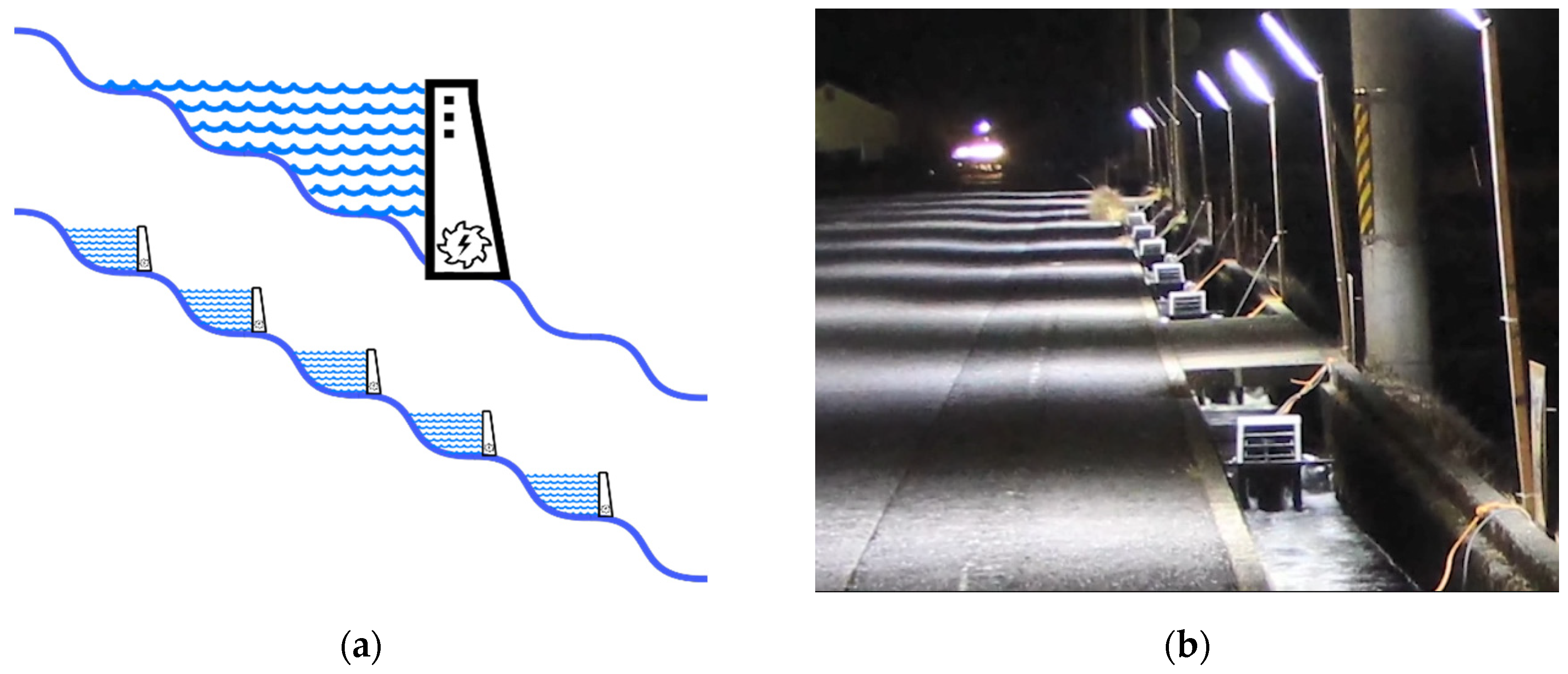
Allowing hydroelectricity generation in regions where construction of large dams is not reasonable or feasible. For example, in relatively smooth plains where suitable conditions do not exist to support the construction of large dams.
-
Maximizing the hydroelectricity generation even in regions where a large dam exists by extracting energy alongside the river downstream.
-
Reducing the electricity power loss alongside the distribution network by generating power near where it is required and consumed, which could reduce the length and cost of the distribution network (such as illustrated in Figure 7b).
-
Generating baseload power with small hydropower plants. Currently, in many locations, the majority of electricity baseload is mainly generated by fossil fuel and nuclear powerplants and hydropower is used to meet peak demands. However, the proposed theoretical chain of ROR powerplants could generate baseload since most of the ROR plants do not store water.

4.2. Reducing Erosion and Disturbance of Natural Sedimentation Processes

Suspended sediments can cause damage passing through traditional turbines i.e., by eroding the component surfaces, especially when sediments are composed of hard materials like quartz and feldspar [74]. To prevent sediment related problems in small hydropower plants, the construction of settling basins to remove sediments is possible [75] but it is often uneconomical [76]. In addition, even if construction and operating costs are ignored, there is no guarantee of complete removal of suspended sediment before the water enters the plant [76]. Unlike many traditional turbines, suspended sediments could pass through ASTs with minimal effect because of their lack of tight tolerances and their low operational speeds [50]. Letting the sediments pass a hydropower plant instead of depositing upstream in reservoirs or settling basins could offer environmental advantages by reducing the disturbance of the natural erosion/sedimentation process while also reducing operating costs associated with settling basin maintenance. Passing sediment could lead to erosion prevention and soil conservation since according to Lane’s law water transporting sediment has less capacity for eroding banks and natural features [77]. Passing sediment through the plant could also offer economic advantages since reduced upstream sediment deposition increases the effective service life of reservoirs and dams.

4.3. Power Generation from Unconventional Water Resources

Considering the advantage of power generation even with a highly sediment contaminated flow with much lower water levels, ASTs could utilize unconventional water resources to generate power. A recent study on micro hydropower plants using sewage water flows indicates that a single AST with a sewage line with a flow rate of about 0.24 m3/s and 1.5 m of the head could generate up to 1963 watts of power [78]. This experiment was physically implemented at the sewage treatment plant for municipal wastewater of Hayatabad Peshawar, Pakistan. It was found that in the worst scenario a coarse screen can be added to prevent the garbage from entering the screw. In addition, increasing the number of screws, flow rate, and head lead to a linear increase in generated power [78]. Moreover, theoretically, sediments could be released continuously from reservoirs, and this flow used for power generation by ASTs.
Another example is the Yorkshire Water’s Esholt wastewater treatment upgrade in 2007 that enables it to generate hydropower from untreated sewage by installing two Archimedean screw generators installed in series (Figure 8) between the inlet works and the new primary settlement tanks [79]. This hydropower plant has been switched on since 2009 [73] and could make use of up to 3.24 m3/s of wastewater with about 10 m of the head passing through a 1.8 m diameter pipe when it flows sequentially through the two screws [79]. The diameter and length of each screw are 2.6 m and 14 m, respectively [73]. This upgrade could provide more than 180 kW of treatment process’ required power [79] of the UK’s first energy self-sufficient (neutral) urban sewage plant [80].

4.4. Conservation and Improvement of Resources

ASTs could offer a considerable value add-on for some big projects whose main purpose is not power generation [79] for improvement or conservation of current resources. The Yorkshire Water’s Esholt wastewater treatment upgrade, which is mentioned in Section 4.3, is one of the examples. In addition, the wide range of AST operating feasibility makes it possible to use them as an upgrade or retrofitting solution at existing dams. Since the civil work associated with the dam already exists, this can reduce capital costs of installing an AST hydropower plant.
Many ASTs have been installed at sites with existing dams. In some cases, the repair costs of a dam could be three times higher than dam removal. Therefore, dam deconstruction may be economically more reasonable than keeping a dam in place, because of maintenance and renovation costs [81]. However, dam removal expenses are usually too high to be covered just by one financer [82]. In addition, many existing dams have been in place for a very long time, and it is not easy to balance the ecosystem and cultural-historical values of such old and historically important structures in communities [83]. The ecosystem and social changes resulting from dam construction usually lead to a new balance over several decades of dam operation [84]. In addition, the deconstruction of old dams provides a large area of stored sediment that is highly suitable to plant colonization. So, native species may fail to survive in competition with aggressive plant colonists [85,86,87].
Few investigations have focused on the dam deconstruction effects on contaminant distribution, especially in the case of small dams with heights less than 2 m [88]. However, some studies about the evaluation of the extent and magnitude of biological and chemical changes caused by dam removal documented potential changes especially in contaminant inventories [89]. As an example, after the Ft. Edwards dam removal in 1973, analysis of the displaced sediment downstream during 1977–1978 indicated highly contaminated polychlorinated biphenyls (PCBs) [90]. Therefore, sometimes the deconstruction of old dams may not be the most effective solution. Each dam deconstruction should be evaluated for the potential sedimentary contaminant redistribution [89] and other possible consequences. Figure 9 is an example of the shock load of releasing sediments deposited in a reservoir during the storage restoration process of Manjil Dam, Iran, in 1982–1983. This sediment shock load caused massive extinction of downstream aquatic life.
Installing an AST at an existing dam or weir can offer economic and environmental benefits by generating renewable hydroelectricity at a previously unutilized site with a minimum of changes to the overall site [20]. An AST installation can also provide a reason for performing deferred and ongoing maintenance on an otherwise neglected dam, improving the structural stability of dam infrastructure [27]. Considering ASTs as a retrofit option could offer environmental advantages, especially if the deconstruction of an old dam may threaten aquatic and wildlife in the downstream. Moreover, as detailed in Section 3.2, such upgrades could help reduce the disturbance of sediment transport processes and realize environmental and economic advantages by implementing renewable hydroelectricity generation.
Many sites such as small weirs or dams without existing hydropower plants are suitable for installing or using ASTs as an upgrade. At existing sites, the dam construction has already been completed, return on investment has been satisfied, and the environmental impacts incurred for many years [52]. The minimum construction requirements of ASTs and their small scale makes the environmental impacts and GHG emission of this upgrade very low [91]. Additionally, such upgrades provide green electricity, which could help to reduce fossil fuel usage and continuous greenhouse gas emissions. Therefore, upgrading dams for hydroelectricity can not only be a reasonable economic decision but it could also partly remediate some prior environmental or social impacts.
For example, within the province of Ontario, Canada, there are approximately 2600, mostly small, dams [92] that were primarily constructed for flood control and milling. About 70% of these dams were constructed prior to 1970. Since the expected service life of a typical small dam ranges between 50 and 70 years, many of these dams will require major restorations or structural repairs within 10 to 15 years because of safety and structural quality concerns [93]. Additionally, in the United States, the Army Corps of Engineers national inventory estimates there are 18,140 dams with heights under 4.6 m that are in need of structural repair due to improper or deferred maintenance [94].
It is also worth mentioning that in the province of Ontario, Canada, nearly one-quarter of all energy production is provided through hydro resources, which are about 90% of all the province’s renewable energy supplies [95]. This represents about 8100 MW of hydroelectricity capacity from 240 dam sites across 24 river systems [96]. Since the focus of increases in hydropower is largely for sites with generating capacity greater than 1 MW [97], sites under 1 MW power generating potential were ignored in this study. However, ASTs could be considered as a reasonable solution for the utilization of these sub-1 MW sites [27].
According to Ontario Hydro and the Ministry of Natural Resources Water Potential Site database, there are approximately 280 sites within Ontario (Figure 10) with less than 200 kW power generating capacity and head less than 5 m [98]. Considering these statistics and typical AST efficiency, the total power generating capacity of ASTs just within Ontario is approximately 16 MW [99]. Therefore, such a retrofitting and upgrade approach could be considered as a low impact development that can provide a considerable amount of energy, especially at the local community level [27].

4.5. AST Plant Configurations

Most early ASTs were designed to operate at one fixed rotation speed [88]. However, variable speed operation is also possible by adding additional electrical equipment and accepting an efficiency reduction. Variable-speed ASTs are a practical solution to deal with large seasonal flow fluctuations. Increasing the AST rotation speed increases the volume of flow that can pass through the AST. However, AST efficiency is reduced when rotation speeds exceed the maximum rotation speed suggested by Muysken relationship (Equation (9)) [100]. In addition, noise becomes a more significant issue at higher rotation speeds. When the volume of flow in a river is so high that an excessively large diameter (exceeding 5 m) or high rotation speed AST (exceeding Equation (10)) would be required to utilize the available flow, a multiple-screw powerplant can be considered. In such cases, two or more ASTs can be installed (typically side by side) instead of a single big screw. When flow at the site is large, all ASTs could be turned on to generate power in their most efficient condition. The extra AST(s) could be turned off at times when the flow is reduced, allowing the remaining AST(s) to operate at closer to optimum conditions.
Therefore, at sites where a considerable fluctuation in river flow is anticipated, plant designers may consider variable-speed ASTs and multi-AST plants in order to effectively utilize available flow at both low flow and high conditions. Using two or more ASTs in a single site could also provide other benefits including easier maintenance, more flexible operation plans, and even some savings in major costs. Currently, AST design is usually based on site specifications, regulatory limitations, and characteristics of available flow. One possibility is that multi-AST powerplants could lead to significant capital cost savings by allowing mass production of highly optimized ASTs in several specific sizes.
Figure 11 shows a crowd-sourced map maintained by Alois Lashofer of the locations of many AST powerplants across the world [101] as of July 2020. The majority of the mapped AST powerplants are single screw plants. However, there are several plants that benefit from more than one screw installation. While most multi-screw installations are in a parallel configuration, there are examples of installations of two plants in series to take advantage of higher head [79] such as the Yorkshire Water’s Esholt wastewater treatment multi-AST hydropower, which is mentioned in Section 4.3.
Figure 12 shows some representative multi-AST powerplants in the United Kingdom. Monmouth New Hydro (Figure 12a) is constructed on the site of the Old Monmouth Hydro Station, which operated from 1899 to 1953. The new hydro scheme uses two ASTs and has been operating since 2009 [102]. This multi-AST powerplant on River Monnow could generate 75 kilowatts of power by each screw, which rotates at only 20 RPM and utilizes 3.4 m of water head [103]. Radyr Hydro Scheme (Figure 12b) applies two 200 kW ASTs with a 3.5 m outer diameter and 10 m length in order to utilize a site on the River Taff with 3.5 m head and a mean flow of 22 m3/s. This powerplant can generate 1.8 million kWh of energy annually, which reduces 785 tons of CO2 emission [104]. Linton Falls Hydro powerplant (Figure 12c) operated from 1909 to 1948. Since 2012 it has been retrofitted by two ASTs that have 2.4 m diameter and 2.7 m of head. The maximum flow rate is 4.5 m3/s [79] and each screw can pass 2.6 m3/s, which results in a combined 100kW of output power at their full capacity [105]. With an annual production of about 500 MWh, this powerplant could save more than 210 tons of CO2 emissions per year [105].
One of the most recent multi-AST powerplants (Q2, 2019) is the Solvay industrial plant, which is installed as a retrofit/upgrade on the small existing weir in Torrevieja, Spain (Figure 13). The entire project was constructed in just 4 months. This plant diverts part of the Saja River and applies two parallel ASTs that are able to produce a total of 70 kW of power (35 kW each) with 2 m of water head and 5 m3/s of flow rate for both turbines. The generated energy will be sold to the electrical grid and the return on investment will be recovered about 7 to 8 years after its start-up date [108].
Even current AST powerplants could upgrade to multi-AST hydropower. Linton Lock powerplant is one of the pioneers in such an approach that benefits from two screws with two different sizes. The first screw was installed in 2012 with a diameter and length of 3 m and 8.5 m, respectively. With 3.2 m of water head and 4.5 m3/s capacity, this screw could offer 101 kW of power output. In 2017, the second screw with a 5 m of diameter was installed beside it, which could be considered as one of the largest screws in the world. With 3 m of water head and 14.5 m3/s capacity, this screw could provide 355 kW of power output [46]. Figure 14 shows this powerplant. The bigger screw is called “Widdington Plant” and the smaller one is called the “Linton Plant.”
Considering the number of installed screws, the Marengo powerplant in Goito, Italy, could be considered as one of the multi-AST hydropower world records since it applies six parallel ASTs. Figure 15 shows this powerplant which is installed on the Mincio River through the Pozzolo-Maglio drain channel and has an average potential of 222.7 kW (up to 306 kW [109]) with 1.6 m of water head and 1.4 and 22.2 m3/s average and maximum flow rates, respectively [110]. Each screw is 3 m in diameter and 4 m in flighted length, and can pass 3.7 m3/s of flow rate with a power of up to 54 kW [109].

4.6. Future Sustainability

According to the United Nations Development Program (UNDP), 1.4 billion individuals had no access to electricity in the past decade [111], especially in poor regions of developing countries [112]. Geographical limitations [113] and uneven population distribution are two important issues in effectiveness of the electrical distribution infrastructure [114]. The structural simplicity, low operational demands, and modest costs make ASTs an environment-friendly and sustainable solution, especially in developing countries. ASTs could be used to generate electricity even with unconventional water resources such as the about 2 kW AST powerplant that runs by sewage water in Hayatabad Peshawar, Pakistan [78]. There have been several investigations proposing pico-hydro ASTs as an electrification solution [115,116] for the 2519 villages in Indonesia that do not have access to electricity because of inaccessible locations [116]. However, only around 1.8% of micro-hydro potential (out of 400 MW potential capacity) is currently exploited in Indonesia as a developing country [117]. Recent studies have examined applying ASTs in small, micro, and even pico scales, and also considered methods to simplify the application of these ASTs. A recent study in Aceh, Indonesia found that even a very simple AST with just one blade ( N = 1 ) with D O = S = 0.26 m, D i = 0.14 m, L = 1 m and β = 30 ° could generate about 116 Watts of power with 1 m of head at a flowrate of 0.02 m3/s and 24.75 rad/s rotation speed [118]. A commercial version of this idea has been developed: currently, the smallest all-in-one portable AST generator from this project weighs just 17.5 kg, and is approximately 1 m long and 0.28 m wide [70]. It could be installed in very shallow waters and can generate around 10 watts of power in a flow of 0.01 m3/s and a head of 0.1 m [45]. Figure 16a shows a diagram of this all-in-one AST generator. This generator could be installed easily, and a 0.15 m tall metal plate helps to provide enough water head to generate power from even a very shallow water. It provides a wide range of new suitable sites to generate electricity. The turbines have been tested in undeveloped regions of Myanmar (Figure 16b) and in urban flows (Figure 16c). The generated power of each unit is very low in comparison to larger plants; however, units could be used in series (Figure 7b) or in parallel (Figure 16d,e) configured as a multi-AST powerplant almost everywhere alongside any flow.
Figure 17 represents the fixed and larger version of this small commercial AST generator that has been installed in Nikko City, Japan, since 2017 [123]. It can generate about 500 W with a flow of 0.1 m3/s and 0.7 m of head [45]. This AST has a net weight of 250 kg and it could generate enough power for nighttime lighting, refrigerators for preserving food and medicine, telecommunication equipment such as cellular phones, and televisions [45]. Systems like these could feasibly provide electricity for poor communities to provide night-time lighting and charging their laptops or mobile phones. Pico-scale ASTs present a flexible and reasonably practical option for improving local economies and welfare in remote, developing communities.

5. Design Archimedes Screw Hydro Powerplants Principles

Figure 18 shows the relationships between AST and the other parts of a simplified AST-based ROR hydropower system. This figure indicates that an Archimedes Screw Turbine (AST) run-of-river (ROR) hydroelectricity powerplant can be considered as a system with three major components: a reservoir, a weir, and the AST (which is connected to the system by a control gate and trash rack). At most real AST locations, the incoming flow must be divided between the AST and a parallel weir. Typically, a minimum flow over the weir is mandated for the protection of the local environment. Therefore, other outlets as well as a fish ladder could be considered as the other components of this system. Therefore, in an AST hydropower plant system, incoming river flow is the input, and the weir overflow, AST outlet flow, and other outlets (i.e., fish ladder flow) are the outputs.

5.1. Archimedes Screw Hydro Powerplants Design Assessments

In order to design an Archimedes screw hydro powerplant, three important assessments should be done: (1) electricity needs assessment and (2) site assessments. Then, the type of screw (fixed/variable speed) should be determined in (3) plant design assessment.
For the electricity needs assessment, it is recommended to:
-
Estimate the required power as well as predict the possible future changes in demand.
-
Determine whether the powerplant will be connected to the grid or will be off-grid.
-
If the AST powerplant is designed to be off-grid, it would be important to:
-
Consider the comparison of the value of reliable baseload power versus maximizing the annual production of the powerplant in making decisions for the design.
-
Define and consider the needed voltages and/or currents.
For the site assessment:
-
Permitting requirements, restrictions on access or water use should be determined.
-
The flow duration curve of the river should be used to determine the baseload and other options for the operation of the powerplant. This information also helps to make decisions in the plant design step.
-
Ecological assessments should be done, and the water needs of other users or ecological functions should be determined. For example, the required flow for fish passage or installing a fish ladder should be determined.
-
The potential plant location should be selected based on the following considerations:
-
Accessibility for construction, operation, and maintenance. This is important for civil works and installation of the screw, especially for larger powerplants that have big and bulky screw(s) that need cranes for installation
-
Geotechnical concerns, particularly stability and suitability for plant foundations
-
Supply channel and outlet channel routing
-
Conflicts with other site use considerations.
In plant design assessment, the type of plant should be selected based on previous assessments:
-
For steady flow, a single-speed plant could be considered as a simpler and more efficient option. On average, the cost per watt of these systems is less than the variable-speed ones. Even if the available flow is not sufficient to fill the screw at its operating speed, fixed speed screws can still generate power in a partially full condition [30].
-
For large surplus flow, variable-speed screws could be recommended to generate partial power at low flow times. It would be particularly important if the powerplant will be off-grid, or other power sources (like diesel generators) are not available or are expensive. Generally, variable-speed screws are recommended when there is an excess flow that could be used to generate more power from an available flow of when the flow varies. The main reason is that although operating ASTs at the full capacity may be the most mechanically efficient operating condition, it will not definitely lead to the highest overall energy generation. Therefore, it may not be the most economically efficient operating condition [30].
For all plant designs:
-
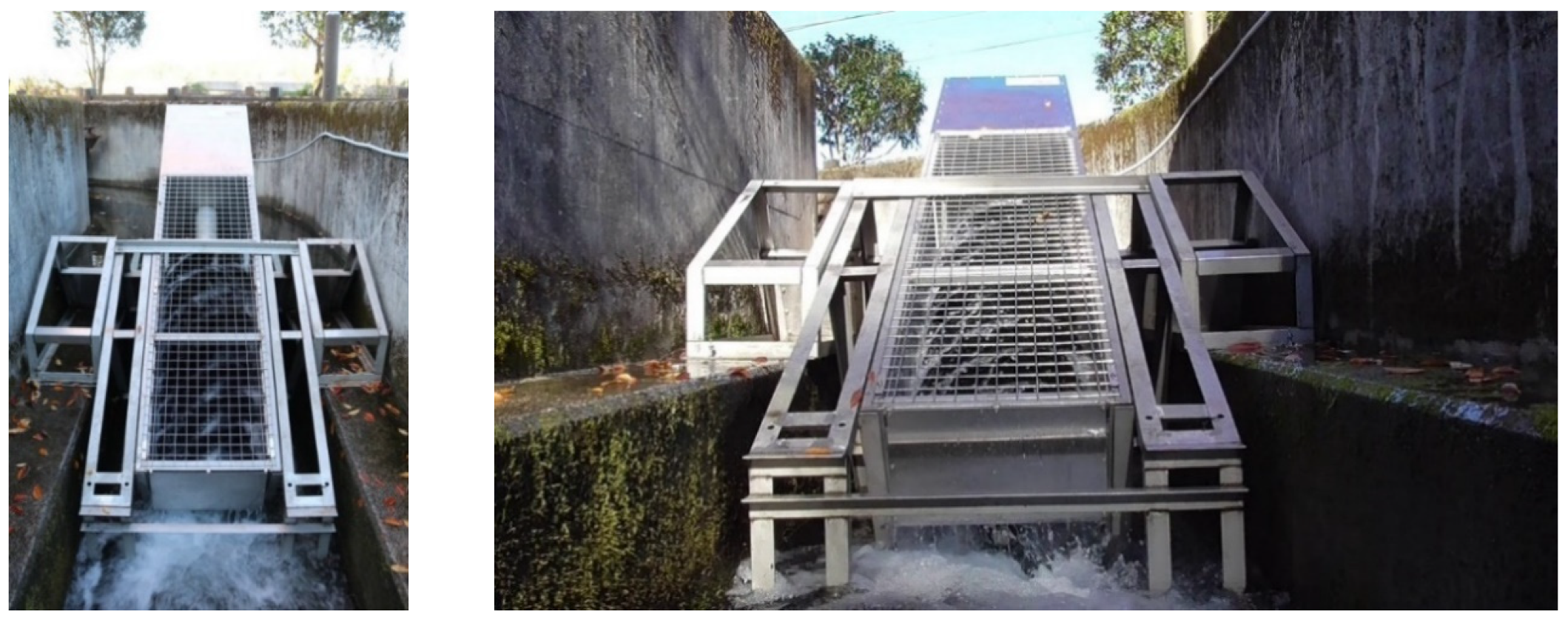
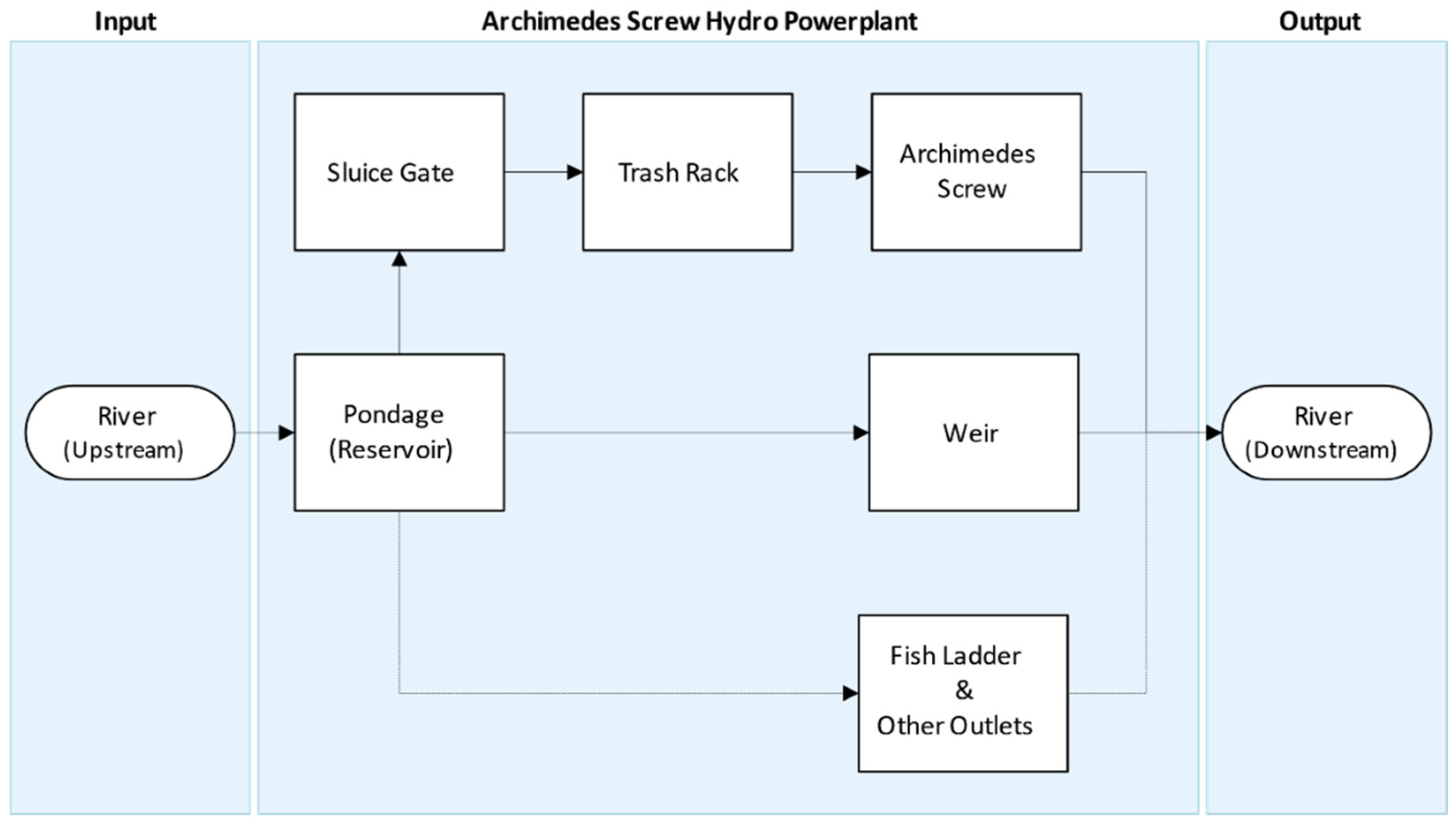
A sluice gate to control flow to the plant, and trash racks to prevent large debris from entering the plant, must be planned upstream of the screw. Ease of trash rack cleaning is important.
-
Provision to dry out the top and bottom of the screw for bearing inspection, maintenance should be included in the plant design. The sluice gate should be able to shut off all flow. At the outlet, build vertical grooves to hold stop logs to allow drying out of the screw outlet.
-
Be sure to plan for flooding water levels, and be sure to protect electrical components from water damage. This could be done by elevating the generator, sealing the powerhouse, and/or putting control equipment on the bank at a higher level.

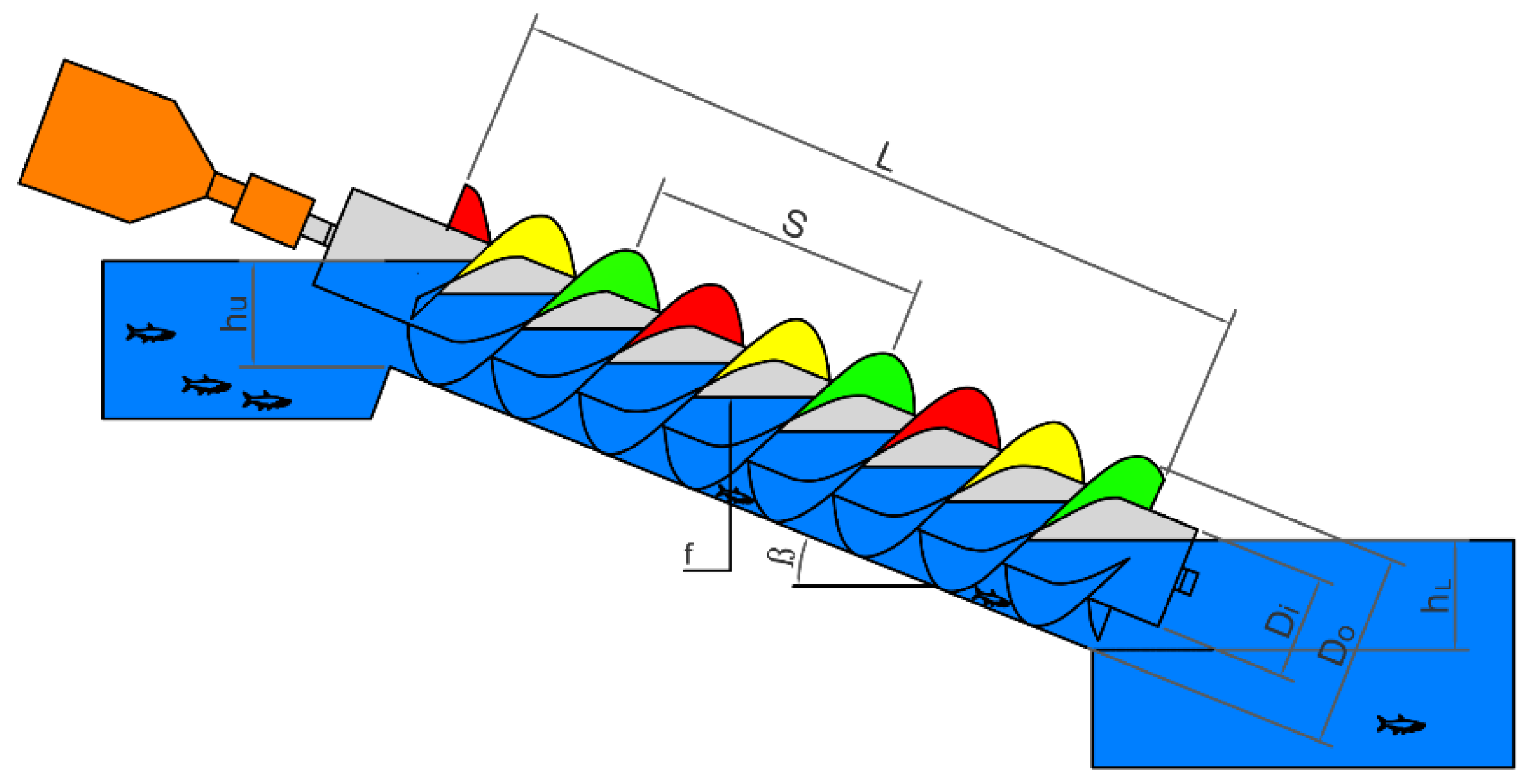
5.2. Design of Archimedes Screws

The Archimedes screw itself is a central component in an Archimedes Screw Hydropower Plant. Figure 19 shows a typical Archimedes screw configured as a hydropower plant and the most important dimensions and parameters required to define the Archimedes screw. These are:
  • Di: Inner diameter
  • DO: Outer diameter
  • L: Total length of the screw
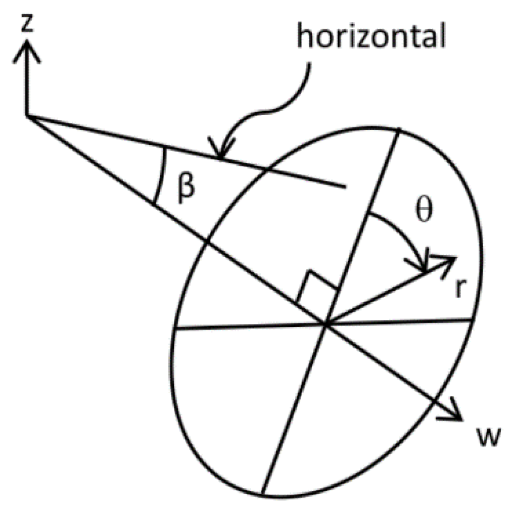
  • β: Inclination Angle of the Screw
  • N: Number of helical planed surfaces
  • S: Screw pitch (Distance along the screw axis for one complete helical plane turn)
  • f: Fill Height of the bucket [30]
  • Gw: The gap between the trough and screw
  • hu: Upper (inlet) water level
  • hL: Lower (outlet) water level
The geometry of an Archimedes screw is determined by external (DO, L, and β) and internal (Di, N, and S) parameters. The external parameters are generally determines based on the location of the screw and the passing flow rate. The internal parameters could be selected in a way that optimizes the performance of the screw [26]. Typically, the screw manufacturer should be involved in detailed design. The following process may be useful for initial planning and preliminary design of an AST site.
First, determine the overall size and inclination angle of the screw. The inclination angle should be determined based on the site slope. If there are minimal constraints on angle (and installation space), a value of β = 22 ° could be considered since many current AST powerplants are installed at a similar inclination angle unless there is a need for steeper slope. Be careful if considering β values in excess of about 30° since screw capacity will decrease markedly, or less than about 20° due to longer screw length. Determine the length (L) of the screw based on site specifications and technical limitations. Use information from existing plants and Equations (10) or Equations (11) to select an overall diameter Do to accommodate the available flow.
Check L/Do. If L/Do is less than about 2, expect efficiency to be somewhat reduced. If L/Do is less than about 1.25, the screw will likely be too short for its diameter. Consider two or more smaller diameter screws, particularly as L/Do gets smaller. Use Equation (10) for screw rotation speed ω, let pitch S = Do and use Di = Do/2. These values will be reasonable for preliminary planning, but may not be optimum values for the final design.
After determination of the geometry of the screw, the algorithm presented by Nuernbergk and Rorres [62] can be used to determine the inlet water head required for optimal operation of the screw to fill it to its optimum volume capacity without occurring overflow. This is needed to vertically position the screw relative to the dam crest or expected reservoir level. The screw must be low enough to ensure it fills completely, but not so low that available head is not utilized. The Archimedes screw power generation model that is introduced in Section 5.3 could be used to estimate the generated power of the designed powerplant. Finally, the net generated power of the Archimedes screw is the difference of the estimated generated power and the power losses introduced in Section 5.4. Finally, the reader is cautioned that the process above, and in the following two sections, should only be used to check feasibility of an AST at a site. Additional design work will be needed to properly optimize the screw plant for a site.

5.3. Estimating the Generated Power of the Archimedes Screws

Despite the literature of using Archimedes screws as pumps, currently, there is little English documentation in using them for extracting energy from flow, and a significant portion of it is about the case studies of installations, many of which are qualitative [30]. Several researchers have worked on developing mathematical models to predict the power output of an Archimedes screw. Early AST power models assumed that the screw was driven by the weight of the water enclosed by the screw blades [25,124]. Essentially, water contained within the buckets of the rotating screw produces a static pressure distribution on all submerged surfaces, and this distribution of pressures results in a net force in the direction of rotation.
Müller and Senior (2009) offered a model based on the hydrostatic pressure difference across the screw surfaces. To consider the effect of gap leakage, they used Nagel’s (1968) empirical equation. However, their model simplifies the screw geometry in a level that they concluded that, by ignoring the bearing and friction losses, theoretically, there is no dependency between the rotation speed and the efficiency of an AST [21,30].
The main assumption for almost all Archimedes screws models is that the water level in each bucket is the highest level at which no water flows to the next bucket over the top of the inner cylinder. There is little theory or data for when ASTs run at partially full conditions [30]. Lubitz et al. [30] proposed a model to estimate the efficiency of screws for all range of possible fill levels. Based on the idea of analyzing a single water bucket, Lubitz et al. [30] proposed several mathematical models to estimate the flow and power of an ideal screw in a steady flow regime. This quasi-static model calculates the volumes of water buckets and the resulting torque on the screw by assuming the screw is not rotating and experiencing no internal water flows [30].
For an ideal screw operating under steady-state conditions (steady flow, constant rotational speed), all the buckets will have the same shape and volumetric size. The shape and size of a bucket are determined by the geometry of the screw, the screw rotation speed ω, and the volume flow rate of water through the screw Q [30]. The model determines the forces and flows operating within a single bucket for an idealized infinitely long screw. It is assumed that all buckets within the screw effectively function identically to this idealized bucket. Forces, torques, and power then can be scaled up based on the total length of the screw (L) to calculate total screw power [30].

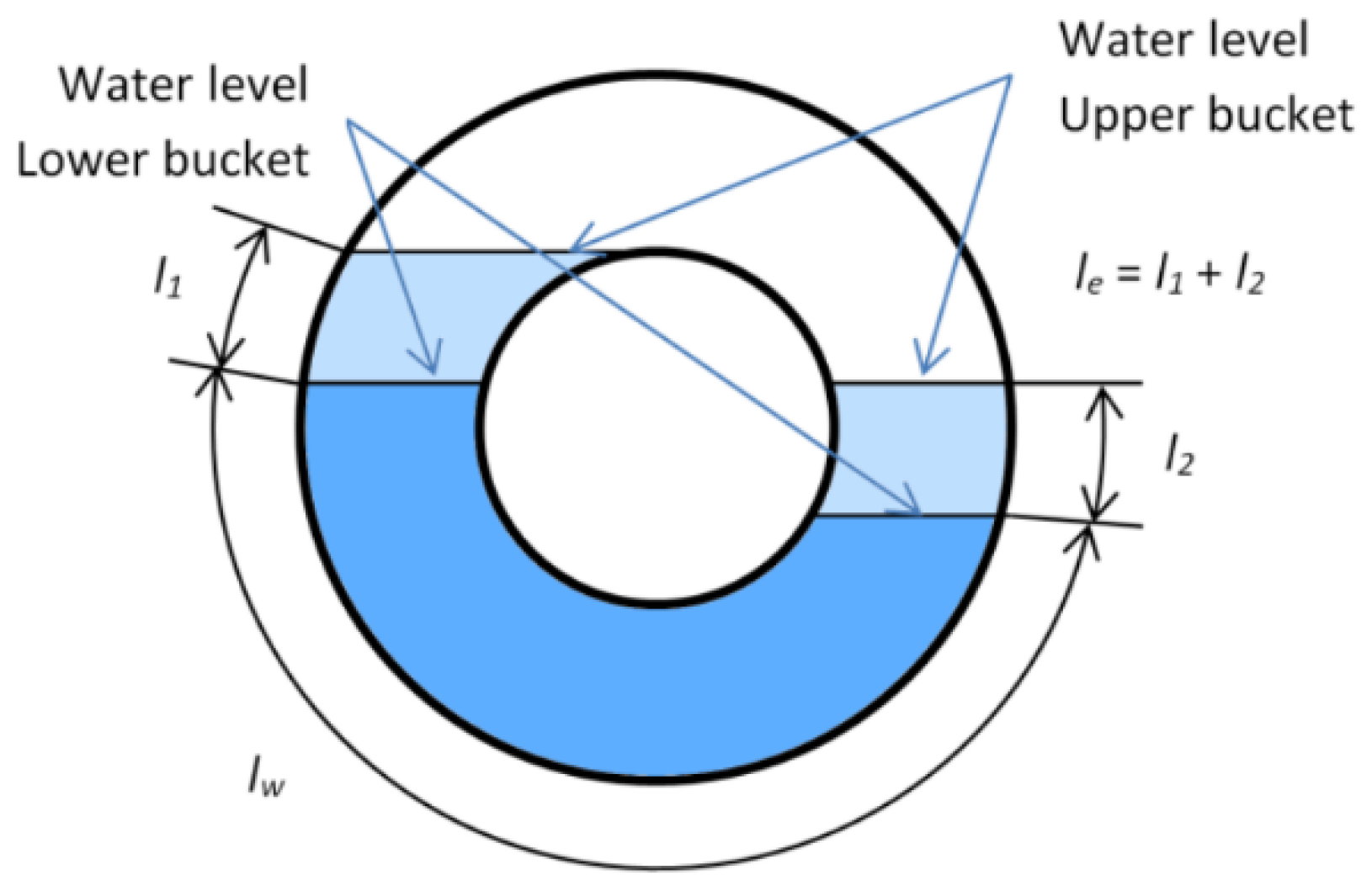
5.3.1. Bucket Volume Theory

The Lubitz et al. [30] model requires defining the general positions on the helical plane surfaces in cylindrical coordinates (Figure 20). A ‘w’ axis is aligned with the rotational axis of the central cylindrical shaft and a vertically oriented Cartesian axis ‘z’ is also defined with positive z vertically upwards. This vertical axis is used to calculate local water depths by projecting physical locations on the helical plane surfaces onto the vertical axis. It is assumed that the first leading helical plane edge is vertically oriented at the top of the screw. So, for any position along the w axis, the radial positions ( r ( ω ) ) and angular positions ( θ ( ω ) ) on the leading plane are described by the geometry of a helicoid of pitch length S. For any given position along the ‘w’ axis [30]:
r ( w ) = r
θ ( w ) = 2 π W S
where r is the radial position, and θ is the angular position (Figure 20). For a screw with the number of blades N , the vertical position on the leading helical plane surface ( Z 1 ) and the upstream helical plane ( Z 2 ) at any point like X ( r ,   θ ) could be defined by [30]:
Z 1 = r   C o s ( θ )   C o s ( β ) S θ 2 π   S i n ( β )
Z 2 = r   C o s ( θ )   C o s ( β ) ( S θ 2 π S N ) S i n ( β )
The minimum fill height can be approximated to occur at θ = π and r = Do/2 and the maximum (100%) fill height occurs at approximately θ = 2 π and r = Di/2. Therefore, the minimum bucket water depth Z m i n , maximum bucket depth without overflowing Z M a x and the actual water depth within the bucket Z w l can be defined and related to the nondimensional water fill height ( f ):
Z m i n = D o 2 C o s ( β ) S 2 S i n ( β )
Z M a x = D i 2 C o s ( β ) S . S i n ( β )
Z w l = Z m i n + Z w l Z m i n Z m a x Z m i n ( Z M a x Z m i n ) = Z m i n + f . ( Z M a x Z m i n )
An infinitesimal, cylindrical volume element ( d V ) can be defined parallel to the ‘w’ axis connecting adjacent points on the helical planes on the upstream and downstream of the bucket. If only the portion of this elemental volume that is submerged below the water line is considered part of the overall water bucket volume, the overall volume of a bucket V can be determined as [30]:
d V = { 0 Z l > Z w l and Z w l < Z 2 Z w l Z 1 Z 2 Z 1   S N   r   d r   d θ Z 1 Z 2 and Z w l Z 2 S N   r   d r   d θ Z l > Z w l and Z w l < Z 2 V = r = D i 2 r = D 0 2   θ = 0 θ = 2   π d V

5.3.2. Flow Rate and Leakage Models

Knowledge of how much water will enter an AST depending on the depth of the water at the inlet is important, since to first order, the amount of power generated by an AST is proportional to the volume flow rate of water through it. Developing a general relationship for the volume of flow passing through an AST as a function of the inlet water level for all screw sizes is challenging because while most water flows through the screw within the buckets formed by the helical array of blades, there is a small gap between the trough and screw which could be considered as free flow. Screw geometry and rotation speed are also important factors that intensify the difficulties. Nuernbergk and Rorres [62] proposed an analytical model for the optimal design of full-scale screws based on the water-inflow conditions for screws running at a fixed speed near to the Muysken’s maximum recommended rotation speed ( ω M ) for Archimedes screws (Equation (9)) [100]. Introducing the concept of effective cross-sectional water area within the screw ( A E ) [125] and axial transport velocity ( V T = S ω / 2 π ), it can be shown that
ω M = 5 π 3 D o 2 / 3
Q = A E V T
Based on a relatively similar concept and by defining the concept of effective area ( A E ) , YoosefDoost and Lubitz [125] developed a new equation for the volume of flow passing through an AST. This nondimensional equation could estimate the total flow rate for different rotation speeds and inlet water levels of the studied lab-scale (small) and full-scale ASTs [125].
Q Q M a x = a ( A E A M a x ) b ( ω ω M ) c
where A M a x = ( π D O 2 / 4 ) , Q M a x is determined from Equation (11) by setting A E = A M a x . The constants a ,   b , and c are related to the screw properties and optimum value may be different for each screw. Preliminary investigations suggest that a = 1.242 , b = 1.311 , and c = 0.822 give reasonable predictions of Q for a range of AST sizes [125].
In addition to the main flow within the buckets, and leakage flow through the gaps between blade and trough, there are several other paths for flow through an AST. The total flow (Q) of an AST can be divided into the following five components: (1) Main flow that is contained with the buckets and causes torque generation ( Q M ), (2) Gap leakage flow ( Q G ), (3) Over filling flow leakage ( Q O ), when water levels within a bucket are so high that some water spills over the top of the central cylinder, (4) Friction-leakage ( Q F ), when water adheres to the flights and is flung out of the screw, and (5) No guiding plate leakage ( Q P ), which occurs when water levels are high enough that water spills out of the top edge of the trough [62]. Total flow Q is the sum of all five of these flow components:
Q = Q M + Q G + Q P + Q O + Q F
It can be assumed that generally, only QM contributes to meaningful power generation, while the other flow components do not contribute useful power and so are ideally minimized or eliminated. In modern screws, Q P is usually eliminated by using a guiding plate to extend the trough to enclose more of the rotating screw. For screws running up to the optimal flow rate, Q O is zero since overflow only happens above the optimum flow rates. Finally, the effect of Q F is usually negligible in ASTs [62].
The gap flow QG is of particular interest, since it is necessary to include a gap between the blades and trough, and so it is not possible to eliminate this component of lost flow. Nagel [126] presented an empirical equation for gap leakage flow in Archimedes screw pumps (not turbines), for the case of full buckets (f = 1) at normal rotational speeds:
Q G = 2.5   G W   D o 1.5
where the G W gap width (in meters) and the diameter (Do) must be entered in units of meters, to get a resulting QG in m3/s. The gap width is not easy to measure in full-scale screws. Nagel also provided an empirical relation to estimate G W based on the size of the screw:
G W = 0.0045 D O
Nagel’s model is necessarily an estimate only, as all physical and dynamic properties of the actual flow regime, rotational mechanics of the screw, and the fluid mechanics of the flow are neglected [126]. Neurnbergk and Rorres proposed a more complex equation attributed to Muysken to estimate gap flow leakage by including some additional parameters [62]:
Q G = μ A G W D O 2 ( 1 + G W D O ) 1 + ( S π D O ) 2 ( 2 3 ( α 3 + α 5 ) + α 4 ) 2 g Δ h
where μ A is the contraction discharge coefficient which is dependent on the shape of the edge of the blade and is typically in the range of between 0.65 and 1 for the minimum and maximum leakage, respectively. The head difference Δ h = ( S / N ) Sin β ) and α 3 , α 4 , and α 5 are wetted angles around the gap (in radians) that can be determined from the algorithm proposed in Rorres (2000) [26,62].
Lubitz et al. [30] presented an equation for QG that is functionally equivalent to the Muysken (1932) [100] and Nuernbergk and Rorres [62] leakage models, but cast in different geometric variables. It assumed that the entire gap leakage is driven by the static pressure difference across the gap, which is the result of the water height difference between adjacent buckets.
Q G = C G w   ( l w + l e 1.5 ) 2 g S N sin β
where C is a minor loss coefficient that is less than or equal to 1 and previously taken to be 0.89; g is the gravitational constant (9.81 m/s2); and l w and l e are wetted lengths along with a single turn of one flight, with l w being the length of the gap that is submerged on both sides, and le being the length of the gap that is submerged on one side and exposed to air on the other (Figure 21).
When bucket fill level exceeds 100% (f > 1), rising the water above the center cylinder causes a secondary flow that lets the water pour over the top of the center cylinder into the downstream bucket. Aigner [62] presented a leakage model based on assuming that the overflow could be approximated as weir flow through a triangular spillway [64]. The weir is approximated as a simple angled, V-notch weir since this is approximately the shape that the central shaft and the planes make at the overflow point [27].
Q O = 4 15   μ 2 g   ( tan β + 1 tan β ) h u e 5
where μ is a loss coefficient and h u e is the overflow head, calculated as [27]
h u e = Z w l Z m a x Z w l > Z m a x
At optimum fill height and below, no spill across the central tube happens, and h u e and also Q O will be zero.

5.3.3. Torque and Power Models

The torque on the screw is the result of water pressure on the helical planes. The Lubitz et al. model determines the hydrostatic pressure p at any point on the plane surfaces at a depth z below the water level by assuming static conditions within the buckets [30]:
p = { ρ g ( Z w l Z ) Z < Z w l 0 Z Z w l
The net pressure on the helical plane surfaces is the difference between the pressure on the up and downstream surfaces of the blade. Therefore, if p1 and p2 are assumed as the pressures on each side of the plane surface, the net torque on each element area of the helical plane surface (dT) and the total torque from a single bucket (T) can be calculated by integrating torque over the entirety of the submerged surfaces:
d T = ( p 1 p 2 ) S θ 2 π   r   d r   d θ
T = r = D i 2 r = D 0 2 θ = 0 θ = 2   π d T
The total torque in full length of screw is related to the total number of buckets and can be calculated by:
T T o t a l = T ( N L S )
Then, the total power will be:
P o u t = T T o t a l ω

5.4. Archimedes Screw Power Loss Models

The discussion above has described the performance of an ideal screw, in which many loss mechanisms are neglected. While overflow and gap leakage flow reduce the overall efficiency of an AST [26,127] and power output can be limited by the amount of water that can enter the screw inlet [62], a complete AST power loss model should consider all possible known head losses [27], which include:
-
Inlet losses due to head loss through the screw entrance
-
Internal hydraulic friction between water and moving screw surfaces
-
Outlet losses due to exit effects, geometric head losses, and additional drag torque
-
Friction of bearings
-
Additional mechanical and electrical losses in gearboxes, generators, and electrical controls
The screw in an AST is supported at both ends by a bearing. Friction losses in bearings reduce torque available at the AST shaft. The magnitude of these losses depends on mechanical properties of the bearing, which may vary from one AST installation to another, and because bearing losses are both relatively low in full-scale ASTs and difficult to predict a priori, there is little guidance in the literature on this loss mechanism. While there are equations in the literature for predicting inlet and hydraulic frictional power losses, most of the outlet power loss calculation attempts are based on adapting equations from related problems [128,129] such as the Borda-Carnot equation for culvert outlet exit power losses. Notably, Nuernbergk presents equations for non-optimal outlet water level loss [28] and Kozyn and Lubitz developed an empirical equation for outlet drag torque power loss [130]. Methods of accurately calculating all of these power losses is a current area of AST research.

6. Conclusions

Archimedes Screws Turbines (ASTs) are a new form of turbines for small hydroelectric powerplants that could be applied even in low head sites. ASTs offer a clean and renewable source of energy. They are safer for wildlife and especially fish. The low rotation speed of ASTs reduces negative impacts on aquatic life and fish.
It is important to note that ASTs are not a uniquely global solution for all energy generation needs. ASTs have their own drawbacks just like any other technologies: using Archimedes screws as generators is a relatively new technology, and in comparison with other hydropower technologies, there are many not well-known things about ASTs. Currently, there are no standards for the design of ASTs, and AST hydro powerplant designs are highly dependent on the experience of the engineer who designs them. For very high flow rates or water heads, a single screw may not take advantage of all available potential due to material, structural, technical, and physical limitations. However, the increasing interest in ASTs, new advancements, and ideas such as multi-AST powerplants offer some solutions to extend AST usability.
ASTs provide a range of practical advantages for generating electrical energy at suitable locations. For supporting sustainable development, ASTs offer economic, social, and environmental advantages. Considering the flexibility and advantages of ASTs, they could be considered as one of the most practical options for a more sustainable electricity generation:
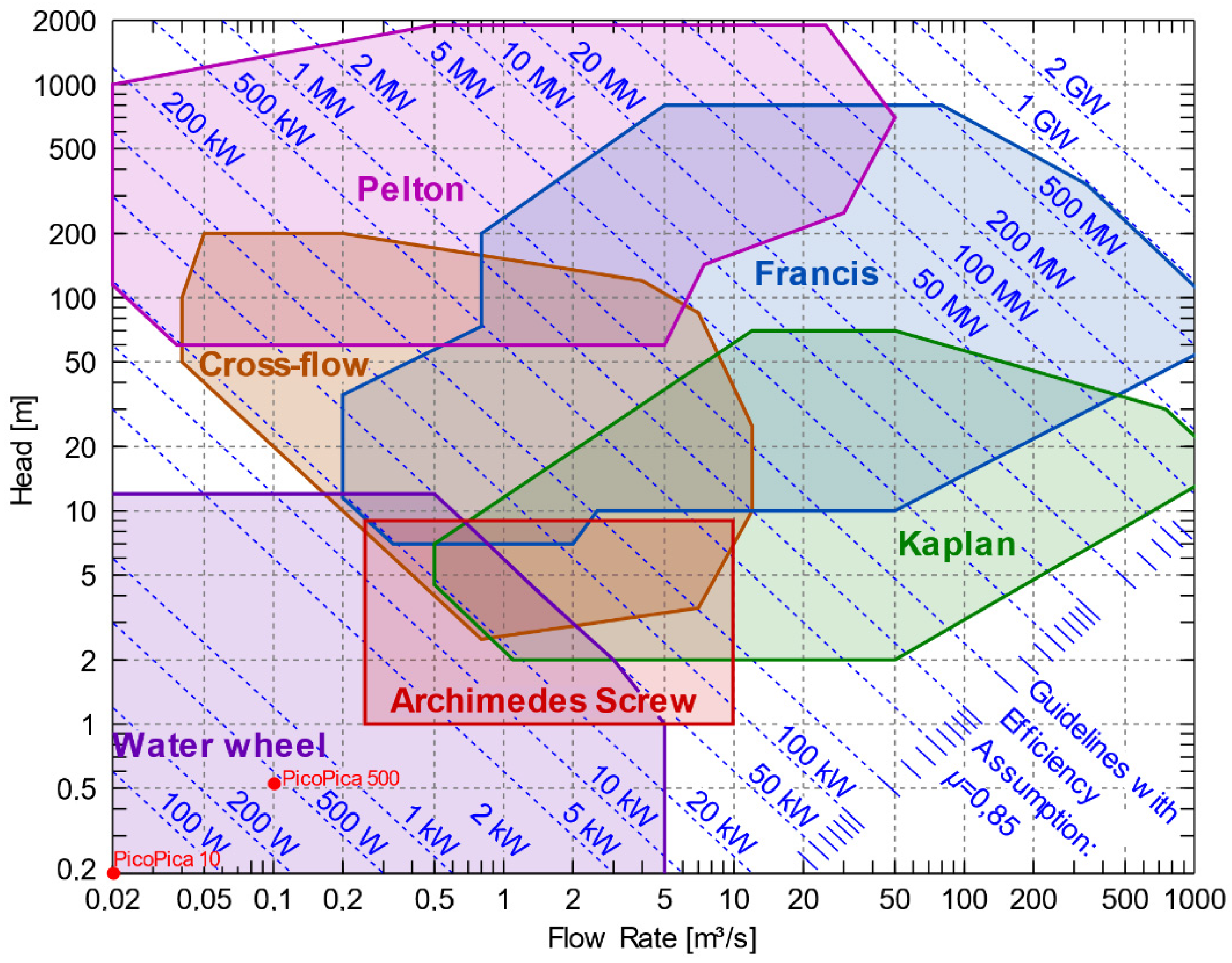
  • To increase the number of suitable sites for power generation even in sites with very low flow rates and/or water head. ASTs can be designed to operate in a wide range of flow rates (currently from 0.01–10 m3/s) and water heads (currently from 0.1–10 m), including at sites where other types of turbines may not be feasible. This increases the number of potentially suitable sites for hydropower.
  • To maximize hydropower generation even in rivers with high flow rate fluctuations. ASTs can handle flow rates even of up to 20% more than optimal filling without a significant loss in efficiency [63]. Even when the conditions are not perfect for a single screw, installing more than one screw, and utilizing variable-speed ASTs, allows developers to fully utilize available flow at a wider range of sites, including those with high seasonal variability.
  • To retrofit old dams or upgrade current dams or mills to make them economically (power generation) and environmentally (renewable energy) reasonable. Using ASTs as an upgrade for retrofitting old dams or upgrading operational dams makes it possible to add electrical generation with extremely low incremental environmental impact, at reasonable costs and with good potential for low social impacts while providing an incentive to maintain aging dams and infrastructure. ASTs utilized in this manner could help to reduce fossil fuel usage and greenhouse gas emissions by displacing electricity generated by more polluting methods.
  • To reduce the hydroelectricity major operational and/or maintenance costs: In addition to retrofit/upgrade current dams advantages, at appropriate sites, the capital costs of AST hydropower can be less than other hydropower technologies. The overall maintenance demands and costs of ASTs are often lower than other turbines. Major maintenance is required after the 20 to 30 years.
  • To reduce the disturbance of natural erosion and sedimentation processes which could lead to soil and land conservation.
  • To make hydropower generation safer for aquatic wildlife, especially for fish.
  • To generate electricity for small communities or regions that are hard to access or connect to the power grid, especially because of the low operation and maintenance demands and costs of ASTs. These characteristics make ASTs a potential candidate for providing electrical power in undeveloped, remote regions, and small communities that currently lack energy infrastructure.
  • To improve the welfare of the developing countries and regions with limited access to the power grid or other infrastructures. Despite many other technologies, ASTs do not require high manufacturing capabilities and hi-tech technologies to design, implement, operate, or maintain. Simplicity, low operational demands, and moderate costs make ASTs a practical environment-friendly and sustainable solution for supplying energy, especially in developing countries. At remote locations with a low head water supply, ASTs may provide a possible means of providing electricity that would otherwise be impractical in developing communities. Improving the economy and welfare of such communities is a win-win futuristic sustainable development approach that could be facilitated by using AST hydroelectric plants.

Author Contributions

Conceptualization, A.Y. and W.D.L.; writing—original draft preparation, A.Y.; writing—review and editing, A.Y. and W.D.L. All authors have read and agreed to the published version of the manuscript.

Funding

This research was funded by the Natural Sciences and Engineering Research Council (NSERC) of Canada, grant number CRDPJ 513923-17.

Acknowledgments

The authors would like to thank Tony Bouk and Brian Weber of Greenbug Energy Inc. for their ongoing support, and Scott Simmons for sharing information and images of his research about the Archimedes screws.

Conflicts of Interest

The authors declare no conflict of interest.

Nomenclature

The following symbols are used in this paper:
A E Effective cross-sectional water area at the screw’s inlet(m2)
A M a x Maximum cross-sectional water area at the screw’s inlet(m2)
a Coefficient of dimensionless flow rate(-)
b Coefficient of dimensionless area constant(-)
c Coefficient of dimensionless rotation speed constant(-)
D i The inner diameter of the Archimedes screw(m)
D O The outer diameter of the Archimedes screw(m)
f Fill height of water in a bucket of screw(-)
g Gravitational constant(9.81 m/s2)
h u Upper (inlet) water level of the screw(m)
h L Lower (outlet) water level of the screw(m)
G w Gap width (The gap between the trough and screw)(m)
h u e Overflow head(m)
L The total length of the screw(m)
l e The wetted gap length along with a single turn of one flight that is submerged on one side and exposed to air on the other(m)
l w The wetted gap length along with a single turn of one flight that is submerged on both sides(m)
N Number of helical planed surfaces(-)
p The hydrostatic pressure at any point on the plane surfaces at a depth z below the water level(Pa)
P O u t Output power/shaft power of screw(W)
Q Total flow rate passing through the screw(m3/s)
Q F Friction-leakage(m3/s)
Q G Gap leakage flow(m3/s)
Q M The main flow that is contained with the buckets and causes torque generation(m3/s)
Q M a x The maximum flow rate that could pass through a screw when ω = ω M and A E = A M a x (m3/s)
Q O Overfilling flow leakage(m3/s)
Q P No guiding plate leakage(m3/s)
rRadial position(m)
S Pitch of the screw (Distance along the screw axis for one complete helical plane turn)(m)
T The torque of a single bucket(Nm)
VThe overall volume of a bucket(m3)
V T Axial transport velocity(m/s)
T T o t a l Total torque of the entire screw(Nm)
w The location along screw centerline(m)
zVertical location(m)
Z m i n Minimum bucket water depth of the screw(m)
Z M a x Maximum bucket depth of screw without overflowing (m)
Z w l The actual water depth within the bucket(m)
α 3 , α 4 , α 5 Wetted angles around the gap(rad)
β The inclination angle of the screw(rad)
Δ h The head difference(m)
θAngular position(rad)
μ Coefficient of the loss
μ A Contraction discharge coefficient
ρ Density of water (1000 kg/m3)
ωThe rotation speed of the screw(rad/s)
ω M The maximum rotation speed of the screw (Muysken limit)(rad/s)
Subscripts
i inner
m i n minimum
M a x Maximum
OOuter
T o t a l Total
w l Water surface level
1 Surface 1 (downstream side of bucket)
2 Surface 2 (upstream side of bucket)

References

  1. Mensah, J.; Ricart Casadevall, S. Sustainable development: Meaning, history, principles, pillars, and implications for human action: Literature review. Cogent Soc. Sci. 2019, 5, 1653531. [Google Scholar] [CrossRef]
  2. UN. Our Common Future: Report of the World Commission on Environment and Development; United Nations: New York, NY, USA, 1987; p. 37. [Google Scholar]
  3. UNICEF; FN-SAMBANDENT. What Is Sustainable Development? 2017. Available online: https://www.youtube.com/watch?v=7V8oFI4GYMY&t (accessed on 29 January 2020).
  4. Passet, R. The Economic and the living (L’Économique et Le Vivant); FeniXX Réédition Numérique, ECONOMICA: Paris, France, 1996. [Google Scholar]
  5. United Nations. Prototype Global Sustainable Development Report; Online Unedited; United Nations Department of Economic and Social Affairs, Division for Sustainable Development: New York, NY, USA, 2014. [Google Scholar]
  6. James, P.; Magee, L.; Scerri, A.; Steger, M.B. Urban Sustainability in Theory and Practice: Circles of Sustainability; Routledge: London, UK, 2015. [Google Scholar]
  7. Shaker, R.R. The spatial distribution of development in Europe and its underlying sustainability correlations. Appl. Geogr. 2015, 63, 304–314. [Google Scholar] [CrossRef]
  8. Dréo, J. Sustainable Development.svg; Wikipedia: Washington, DC, USA, 2007; Available online: https://en.wikipedia.org/wiki/File:Sustainable_development.svg (accessed on 3 December 2018).
  9. Ellabban, O.; Abu-Rub, H.; Blaabjerg, F. Renewable energy resources: Current status, future prospects and their enabling technology. Renew. Sustain. Energy Rev. 2014, 39, 748–764. [Google Scholar] [CrossRef]
  10. Appavou, F.; Brown, A.; Epp, B.; Gibb, D.; Kondev, B.; McCrone, A.; Murdock, H.E.; Musolino, E.; Ranalder, L.; Sawin, J.L.; et al. Renewables 2019 Global Status Report; REN21 Secretariat: Paris, France, 2019. [Google Scholar]
  11. McNally, A.; Magee, D.; Wolf, A.T. Hydropower and sustainability: Resilience and vulnerability in China’s powersheds. J. Environ. Manag. 2009, 90, S286–S293. [Google Scholar] [CrossRef]
  12. Williamson, S.J.J.; Stark, B.H.H.; Booker, J.D.D. Low head pico hydro turbine selection using a multi-criteria analysis. RENE 2014, 61, 43–50. [Google Scholar] [CrossRef]
  13. Date, A.; Akbarzadeh, A. Design and cost analysis of low head simple reaction hydro turbine for remote area power supply. Renew. Energy 2009, 34, 409–415. [Google Scholar] [CrossRef]
  14. Lafitte, R. Survey of Energy Resources; World Energy Council: London, UK, 2001. [Google Scholar]
  15. Cleveland, C.J.; Morris, C.G. Handbook of Energy: Chronologies, Top Ten Lists, and Word Clouds; Elsevier: Waltham, MA, USA; Amesterdam, The Netherlands; Oxford, UK, 2013; Volume 2. [Google Scholar]
  16. Icold. Role of Dams. International Commission on Large Dams, 2014. Available online: http://www.icold-cigb.org/GB/Dams/role_of_dams.asp (accessed on 7 July 2020).
  17. Born, S.; Field, K.; Lander, D.; Bendewald, M. Water Resources: Why Do We Build Dams? Teach Engineering. 2007. Available online: https://www.teachengineering.org/lessons/view/cub_dams_lesson01 (accessed on 3 May 2020).
  18. Casini, M. Harvesting energy from in-pipe hydro systems at urban and building scale. Int. J. Smart Grid Clean Energy 2015, 4, 316–327. [Google Scholar] [CrossRef] [Green Version]
  19. IRENA. Renewable Energy Techlogies: Cost Analysis Series, Hydropower; Volume 1, no. 3/5; IRENA Innovation and Technology Centrer: Bonn, Germany, 2012. [Google Scholar]
  20. Suh, S.H.; Kim, K.Y.; Kim, B.H.; Kim, Y.T.; Kim, T.G.; Roh, H.W.; Yoo, Y.I.; Park, N.H.; Park, J.M.; Shin, C.S.; et al. Theory and Applications of Hydraulic Turbines, 1st ed.; Dong Myeong Publishers: Paju, Gyeonggi-do, Korea, 2014. [Google Scholar]
  21. Muller, G.; Senior, J. Simplified theory of Archimedean screws Théorie simplifiée de la vis d’Archimède. J. Hydraul. Res. 2009, 47, 666–669. [Google Scholar] [CrossRef]
  22. Simmons, S.; Lubitz, W. Archimedes screw generators for sustainable energy development. In Proceedings of the 2017 IEEE Canada International Humanitarian Technology Conference (IHTC), Toronto, ON, Canada, 21–22 July 2017; pp. 144–148. [Google Scholar] [CrossRef]
  23. Koetsier, T.; Blauwendraat, H. The Archimedean Screw-Pump: A Note on Its Invention and the Development of the Theory. In International Symposium on History of Machines and Mechanisms; Springer: Dordrecht, The Netherlands, 2004; pp. 181–194. [Google Scholar]
  24. Dalley, S.; Oleson, J.P. Sennacherib, Archimedes, and the Water Screw: The Context of Invention in the Ancient The Context of Invention in the Ancient World. Technol. Cult. 2003, 44, 1–26. [Google Scholar] [CrossRef]
  25. Brada, K. Wasserkraftschnecke ermöglicht Stromerzeugung über Kleinkraftwerke [Hydraulic screw generates electricity from micro hydropower stations]. Masch. Würzbg 1999, 105, 52–56. [Google Scholar]
  26. Rorres, C. The Turn of the Screw: Optimal Design of an Archimedes Screw. J. Hydraul. Eng. 2000, 126, 72–80. [Google Scholar] [CrossRef] [Green Version]
  27. Kozyn, A. Power Loss Model for Archimedes Screw Turbines. Master’s Thesis, University of Guelph, Guelph, ON, Canada, 2016. [Google Scholar]
  28. Lashofer, A.; Hawle, W.; Pelikan, B. State of technology and design guidelines for the Archimedes screw turbine. In Proceedings of the Hydro 2012—Innovative Approaches to Global Challenges, Bilbao, Spain, 29–31 October 2012. [Google Scholar]
  29. Kibel, P. Fish Monitoring and Live Fish Trials. In Archimedes Screw Turbine, River Dart, No. Phase 1 Report: Live Fish Trials, Smolts, Leading Edge Assessment, Disorientation Study, Outflow Monitoring; Moretonhampstead Fishtek Consult. Ltd.: Moretonhampstead, Devon, UK, 2007; Volume September, pp. 1–40. [Google Scholar]
  30. Lubitz, W.D.; Lyons, M.; Simmons, S. Performance Model of Archimedes Screw Hydro Turbines with Variable Fill Level. J. Hydraul. Eng. 2014, 140, 04014050. [Google Scholar] [CrossRef]
  31. Lynch, A.J.; Rowland, C.A. The History of Grinding; Society for Mining, Metallurgy, and Exploration: Littleton, CO, USA, 2005. [Google Scholar]
  32. Siyavula. Water-Wheels. Openstax CNX. 10 September 2009. Available online: https://cnx.org/contents/IRxiIGmY@1/Water-wheels (accessed on 13 May 2020).
  33. Werner, H.; Alois, L.; Bernhard, P. Lab Testing of the Archimedean Screw. In Proceedings of the Hidroenergia Conference, Wroclaw, Poland, 23–26 May 2012. [Google Scholar]
  34. Rorres, C. Archimedes in the 21st Century: Proceedings of a World Conference at the Courant Institute of Mathematical Sciences; Springer Basel AG: Cham, Switzerland, 2017. [Google Scholar]
  35. Schwizer, J. Map of Hydro Turbines. WikiMedi. 16 February 2018. Available online: https://commons.wikimedia.org/wiki/File:Kennfeld_Wasserturbinen.svg (accessed on 23 August 2020).
  36. Voith-Siemens. Plan View of a Pelton Turbine Installation. Voith Siemens Hydro Power Generation, 16 December 2005. Available online: https://en.wikipedia.org/wiki/File:S_vs_pelton_schnitt_1_zoom.png (accessed on 23 August 2020).
  37. Breeze, P.A. Power Generation Technologies, 3rd ed.; Elsevier: Amsterdam, The Netherlands, 2019. [Google Scholar]
  38. Bermiego. Turgo Turbine. WikiPedia. 29 April 2005. Available online: https://en.wikipedia.org/wiki/File:Turgo_turbine.png (accessed on 23 August 2020).
  39. Subramanya, K. Hydraulic Machines; McGraw Hill Education (India) Private: New Delhi, India, 2013. [Google Scholar]
  40. Elbatran, A.H.; Yaakob, O.B.; Ahmed, Y.M.; Shabara, H.M. Operation, performance and economic analysis of low head micro-hydropower turbines for rural and remote areas: A review. Renew. Sustain. Energy Rev. 2015, 43, 40–50. [Google Scholar] [CrossRef]
  41. Voith-Siemens. Sectional Drawing of a Francis Turbine for the Xingu Power Plant, Brazil. WikiMedia. 16 December 2005. Available online: https://commons.wikimedia.org/wiki/File:M_vs_francis_schnitt_1_zoom.jpg (accessed on 23 August 2020).
  42. Schweiss, M. Sectional Drawing of a Kaplan Turbine with a Diameter of 9.5 m for Yacyretá, Argentina. WikiMedia. 31 December 2005. Available online: https://commons.wikimedia.org/wiki/File:S_vs_kaplan_schnitt_1_zoom.jpg (accessed on 23 August 2020).
  43. Durgaiah, D.R. Fluid Mechanics and Machinery; New Age International: New Delhi, India, 2007. [Google Scholar]
  44. Quaranta, E.; Revelli, R. Gravity water wheels as a micro hydropower energy source: A review based on historic data, design methods, efficiencies and modern optimizations. Renew. Sustain. Energy Rev. 2018, 97, 414–427. [Google Scholar] [CrossRef]
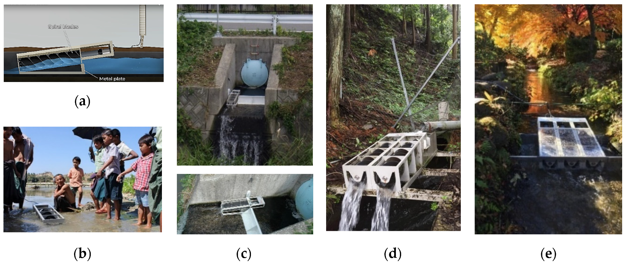
  45. UNIDO. Renewable Energy: Micro Hydraulic Power Unit (Spiral Type Pico-Hydro Unit ‘PicoPica10′, ‘PicoPica500′); United Nations Industrial Development Organization: Tokyo, Japan, 2020; Available online: http://www.unido.or.jp/en/technology_db/5276/ (accessed on 7 July 2020).
  46. Landustrie. Linton Lock. Landustrie Sneek BV, 2017. Available online: https://www.landustrie.nl/en/products/hydropower/projects/linton-lock.html (accessed on 29 July 2020).
  47. ANDRITZ (Formerly Ritz-Atro). Hydrodynamic Screws: Energy Extraction-Efficient and Fish-Friendly; ANDRITZ (Formerly Ritz-Atro): Nurnberg, Germany, 2006. [Google Scholar]
  48. Senior, J.A. Hydrostatic Pressure Converters for the Exploitation of Very Low Head Hydropower Potential. Ph.D. Thesis, University of Southampton, Southampton, UK, 2009. [Google Scholar]
  49. Adlard, J. Archimedes Screw: Copley Hydropower Generator; Future Energy Yorkshire: Leeds, UK, 2011. [Google Scholar]
  50. Bennion, D. Maintaining Archimedes Screw Pumps. ECS Engineering Services, 2013. Available online: http://www.ecsengineeringservices.com/maintaining-archimedes-screw-pumps/ (accessed on 26 June 2018).
  51. ECS. Archimedes Screw Pumps. ECS Engineering Services, 2018. Available online: http://www.ecsengineeringservices.com/archimedes-screw-pumps/ (accessed on 26 June 2018).
  52. SBH. Archimedean Screw Turbine; Spaans Babcock B.V., Spaans Babcock Hydro Power: Balk, The Netherlands, 2012. [Google Scholar]
  53. Dada, O.M.; Daniyan, I.A.; Adaramola, O. Optimal Design of Micro Hydro Turbine (Archimedes Screw Turbine) in Arinta Waterfall in Ekiti State, Nigeria. Res. J. Eng. Appl. Sci. 2014, 4, 34–38. [Google Scholar]
  54. Pringle, C.M.; Freeman, M.C.; Freeman, B.J. Regional Effects of Hydrologic Alterations on Riverine Macrobiota in the New World: Tropical-Temperate ComparisonsThe massive scope of large dams and other hydrologic modifications in the temperate New World has resulted in distinct regional trends of biotic impoverishment. While neotropical rivers have fewer dams and limited data upon which to make regional generalizations, they are ecologically vulnerable to increasing hydropower development and biotic patterns are emerging. Bioscience 2000, 50, 807–823. [Google Scholar] [CrossRef] [Green Version]
  55. Neves, R.J.; Bogan, A.E.; Williams, J.D.; Ahlstedt, S.A.; Hartfield, P.W. Status of Aquatic Mollusks in the Southeastern United States: A Downward Spiral of Diversity. In Aquatic Fauna in Peril: The Southeastern Perspective; Lenz Design and Communications: Decatur, GA, USA, 1997; pp. 43–86. [Google Scholar]
  56. Boys, C.A.; Pflugrath, B.D.; Mueller, M.; Pander, J.; Deng, Z.D.; Geist, J. Physical and hydraulic forces experienced by fish passing through three different low-head hydropower turbines. Mar. Freshw. Res. 2018, 69, 1934–1944. [Google Scholar] [CrossRef]
  57. McNabb, C.D.; Liston, C.R.; Borthwick, S.M. Passage of Juvenile Chinook Salmon and other Fish Species through Archimedes Lifts and a Hidrostal Pump at Red Bluff, California. Trans. Am. Fish. Soc. 2003, 132, 326–334. [Google Scholar] [CrossRef]
  58. Kibel, P.; Pike, R.; Coe, T. Archimedes Screw Turbine Fisheries Assessment. Phase II: Eels and Kelts; Fishtek Consulting Ltd.: Moretonhampstead, UK, 2008. [Google Scholar]
  59. Kibel, P.; Pike, R.; Coe, T. The Archimedes Screw Turbine: Assessment of Three Leading Edge Profiles; Fishtek Consulting Ltd.: Moretonhampstead, UK, 2009. [Google Scholar]
  60. United Kingdom Environment Agency. Hydropower Good Practice Guidelines Screening requirements. J. Hydraul. Res. 2012, 4, 1–16. [Google Scholar]
  61. Piper, A.T.; Rosewarne, P.J.; Wright, R.M.; Kemp, P.S. The impact of an Archimedes screw hydropower turbine on fish migration in a lowland river. Ecol. Eng. 2018, 118, 31–42. [Google Scholar] [CrossRef]
  62. Nuernbergk, D.M.; Rorres, C. Analytical Model for Water Inflow of an Archimedes Screw Used in Hydropower Generation. J. Hydraul. Eng. 2013, 139, 213–220. [Google Scholar] [CrossRef]
  63. Brada, K.; Radlik, K.-A. Wasserkraftschnecke: Eigenschaften und Verwendung. In Heat Exchange and Renewable Energy Sources; International Symposium: Szczecin, Poland, 1996; pp. 43–52. [Google Scholar]
  64. Aigner, D. Current Research in Hydraulic Engineering 1993–2008; Institut für Wasserbau und Technisch Hydromechanik der TU Association: Dresden, Germany, 2008. [Google Scholar]
  65. Schmalz, W. Studies on fish migration and control of possible fish loss caused by the hydrodynamic screw and hydropower plant. In Fischo—Kologische und Limnol. Untersuchungsstelle Sudthurign, Rep.; Thüringer Landesanstalt für Umwelt und Geol: Jena, Germany, 2010. [Google Scholar]
  66. Lashofer, A.; Kaltenberger, F.; Pelikan, B. Does the archimedean screw turbine stand the test? (Wie gut bewährt sich die Wasserkraftschnecke in der Praxis?). Wasserwirtschaft 2011, 101, 76–81. [Google Scholar] [CrossRef]
  67. Nuernbergk, D.M. Wasserkraftschnecken—Berechnung und Optimaler Entwurf von Archimedischen Schnecken als Wasserkraftmaschine (Hydro-Power Screws—Calculation and Design of Archimedes Screws), 2nd ed.; Verlag Moritz Schäfer: Detmold, Germany, 2020. [Google Scholar]
  68. Fraenkel, P.; Paish, O.; Harvey, A.; Brown, A.; Edwards, R.; Bokalders, V. Micro-Hydro Power: A Guide for Development Workers; Intermediate Technology Publications: London, UK, 1999. [Google Scholar]
  69. NationalTrust. Hydropower Returns to Cragside|National Trust. 2020. Available online: https://www.nationaltrust.org.uk/features/hydropower-returns-to-cragside (accessed on 1 July 2020).
  70. Sumino, M. Ultra-Small Water Power Generator. 14 May 2019. Available online: https://youtu.be/XjEgFlngZ04 (accessed on 23 June 2020).
  71. Rosser. The Cragside Estate Archimedes Screw Water Turbine and Generator. Rothbury, England. Wikimedia Commons. 14 October 2016. Available online: https://commons.wikimedia.org/wiki/File:The_Cragside_Estate_Archimedes_screw_water_turbine_and_generator,_Rothbury,_England.jpg (accessed on 5 July 2020).
  72. Down, C. Cragside Archimedes’ Screw from Bottom. Wikimedia Commons. 17 May 2017. Available online: https://commons.wikimedia.org/wiki/File:Cragside_Archimedes%27_screw_from_bottom.jpg (accessed on 5 July 2020).
  73. Spaans Babcock Ltd. Hydro Power Using Waste Water at Esholt WwTW. Spaans Babcock Ltd., 2009. Available online: https://cms.esi.info/Media/documents/54053_1316689157666.pdf (accessed on 29 July 2020).
  74. Padhy, M.K.; Saini, R.P. A review on silt erosion in hydro turbines. Renew. Sustain. Energy Rev. 2008, 12, 1974–1987. [Google Scholar] [CrossRef]
  75. Awasthi, A.K. Design for Small hydro-An Innovative Approach. In Proceedings of the 2nd International Conference on Silting Problems in Hydropower Plants, Bangkok, Thailand, 26–28 September 2001; pp. 83–89. [Google Scholar]
  76. Kang, M.W.; Park, N.; Suh, S.H. Numerical Study on Sediment Erosion of Francis Turbine with Different Operating Conditions and Sediment Inflow Rates. Procedia Eng. 2016, 157, 457–464. [Google Scholar] [CrossRef] [Green Version]
  77. Rinaldi, M.; Gurnell, A.M.; Belletti, B.; Berga Cano, M.I.; Bizzi, S.; Bussettini, M.; del Tánago, M.; Grabowski, R.; Habersack, H.; Klösch, M.; et al. Final Report on Methods, Models, Tools to Assess the Hydromorphology of Rivers. 2015. Available online: https://reformrivers.eu/ (accessed on 7 September 2020).
  78. Durrani, A.M.; Uzair, M. Micro Hydro Power Plant using Sewage Water of Hayatabad Peshawar. In Proceedings of the 2019 15th International Conference on Emerging Technologies (ICET), Peshawar, Pakistan, 2–3 December 2019. [Google Scholar]
  79. IWPDC. A Quiet Revolution. International Water Power & Dam Construction. 29 November 2010. Available online: https://www.waterpowermagazine.com/features/featurea-quiet-revolution/ (accessed on 6 July 2020).
  80. Yorkshire Water. Words Of Water: UK’s First Energy Self-Sufficient Large Sewage Works. Yorkshire Water, 2014. Available online: http://wordsofwater.blogspot.com/2012/01/uks-first-energy-self-sufficient-large.html (accessed on 29 July 2020).
  81. Born, S.M.; Genskow, K.D.; Filbert, T.L.; Hernandez-Mora, N.; Keeper, M.L.; White, K.A. Socioeconomic and institutional dimensions of dam removals: The Wisconsin experience. Environ. Manag. 1998, 22, 359–370. [Google Scholar] [CrossRef] [PubMed]
  82. Babbit, B. What Goes Up, May Come Down. New Sci. 2002, 52, 656–658. [Google Scholar] [CrossRef] [Green Version]
  83. Lejon, A.G.C. Ecosystem Response to Dam Removal; Department of Ecology and Environmental Science, Umeå University: Umeå, Sweden, 2012. [Google Scholar]
  84. Tahmiscioğlu, M.S.; Durmuş, N. Positive and negative impacts of dams on the environment. In Proceedings of the International Congress On River Basin Management, Ankara, Turkey, 8 March 2007; pp. 759–769. [Google Scholar]
  85. D’Antonio, C.; Meyerson, L.A. Exotic plant species as problems and solutions in ecological restoration: A synthesis. Restor. Ecol. 2002, 10, 703–713. [Google Scholar] [CrossRef] [Green Version]
  86. Shafroth, P.B.; Friedman, J.M.; Auble, G.T.; Scott, M.L.; Braatne, J.H. Potential Responses of Riparian Vegetation to Dam Removal. Bioscience 2002, 52, 703–712. [Google Scholar] [CrossRef] [Green Version]
  87. Orr, C.H.; Stanley, E.H. Vegetation development and restoration potential of drained reservoirs following dam removal in Wisconsin. River Res. Appl. 2006, 22, 281–295. [Google Scholar] [CrossRef]
  88. Grant, G. Dam removal: Panacea or Pandora for rivers? Hydrol. Process. 2001, 15, 1531–1532. [Google Scholar] [CrossRef]
  89. Ashley, J.T.F.; Bushaw-Newton, K.; Matt, W.; Boettner, A.; Drames, G.; Velinsky, D.J. The Effects of Small Dam Removal on the Distribution of Sedimentary Contaminants. Environ. Monit. Assess. 2006, 114, 287–312. [Google Scholar] [CrossRef]
  90. Hetling, L.; Horn, E.; Tofflemire, J. Summary of Hudson River PCB Study Results; NYS Department of Environmental Conservation: New York, NY, USA, 1978.
  91. Waters, S.; Aggidis, G.A. Over 2000 years in review: Revival of the Archimedes Screw from Pump to Turbine. Renew. Sustain. Energy Rev. 2015, 51, 497–505. [Google Scholar] [CrossRef] [Green Version]
  92. Keyes, J.; Pastinak, O. MNR’s Role in Public Safety Around Dams—An Overview. Ministry of Natural Resources, Biodiversity Branch Policy Division. Presentation to Ontario Waterpower Association. 11 April 2011. Available online: https://slideplayer.com/slide/6376193/ (accessed on 9 May 2020).
  93. Demal, L. Dam Safety in Ontario New Dam Safety Technical Guidelines—What do they mean for Ontario? Ministry of Natural Resources. In Proceedings of the Ontario Waterpower Association—Annual Power of Water Conference, Niagara-on-the Lake, ON, Canada, 23 October 2012. [Google Scholar]
  94. ASDSO. The Cost of Rehabilitating Our Nation’s Dams: A Methodology, Estimate & Proposed Funding Mechanisms; Association of State Dam Safety Officials: Lexington, KY, USA, 2016.
  95. Ontario Energy Board. Ontario’s System-Wide Electricity Supply Mix: 2013 Data; Ontario Energy Board: Toronto, ON, Canada, 2014. [Google Scholar]
  96. Ontario Ministry of Energy. Ontario’s Long-Term Energy Plan; Queen’s Printer for Ontario: Toronto, ON, Canada, 2010.
  97. Hatch Acres. Evaluation and Assessment of Ontario’s Waterpower Potential Ministry of Natural Resources Final Report; Hatch Acres: Peterborough, ON, Canada, 2005. [Google Scholar]
  98. Ontario Ministry of Natural Resources. Potential Waterpower Generation Sites (WPPOTSTE). Ontario Ministry of Natural Resources, 2004. Available online: https://www.ontario.ca/data/potential-waterpower-generation-sites-wppotste (accessed on 10 January 2015).
  99. Kozyn, A.; Ash, S.; Lubitz, W.D. Assessment of Archimedes Screw Power Generation Potential in Ontario. In Proceedings of the 4th Climate Change Technology Conference, Montreal, QC, Canada, 25–27 May 2015; no. 1570095585. pp. 1–11. [Google Scholar]
  100. Muysken, J. Calculation of the Effectiveness of the Auger. De Ingenieur 1932, 21, 77–91. [Google Scholar]
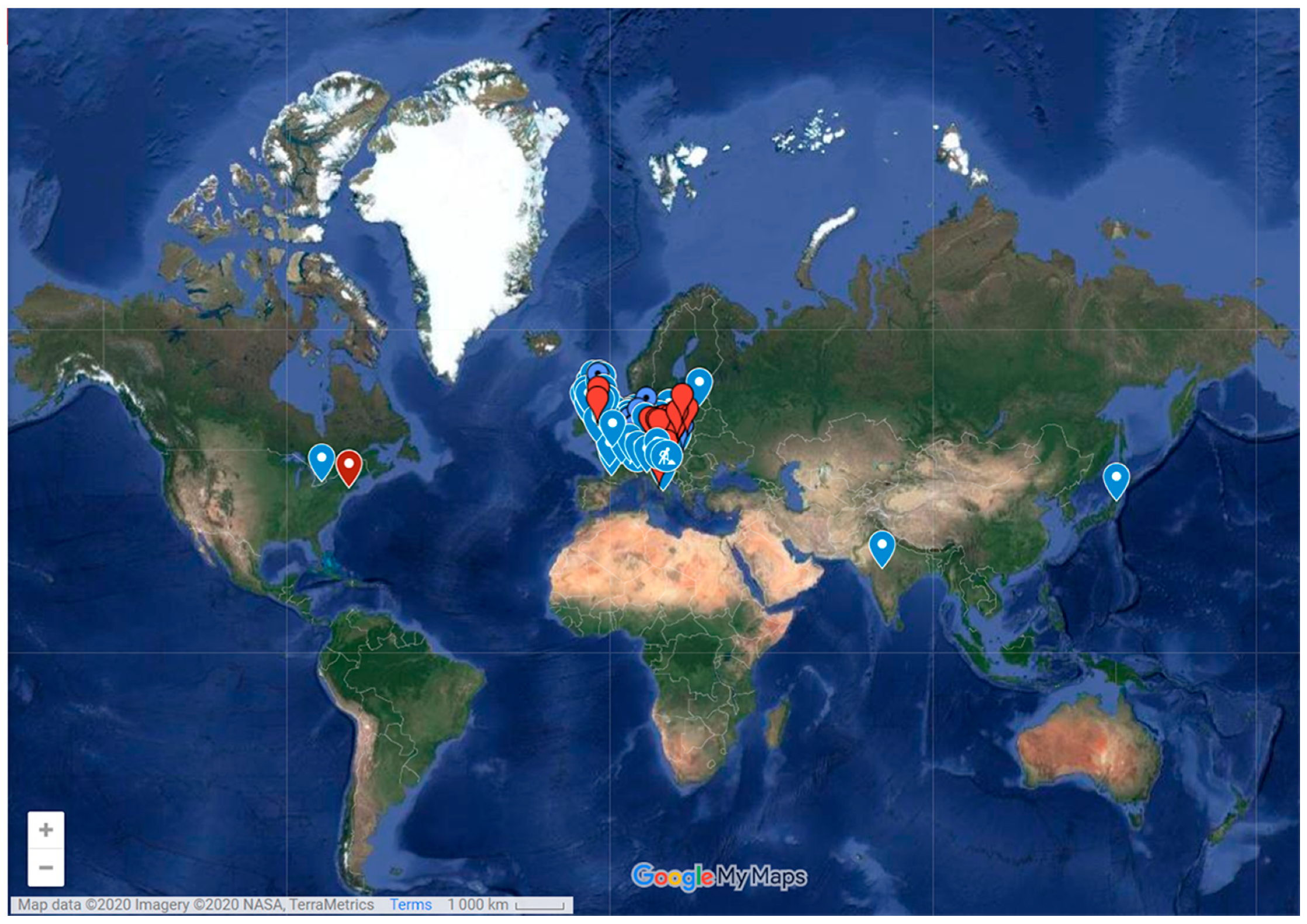
  101. Lashofer, A. Project Hydropower Screw Location—Ingenieurbüro Lashofer! Lashofer Ingenieurbüro für Wasserwirtschaft. Available online: https://www.lashofer.at/deutsch/wasserkraftschnecke/projekt-wasserkraftschnecken-verortung/ (accessed on 4 July 2020).
  102. AberdareOnline. Weir—D What Ronald Kear Knows about Archimedes, the Royal Family and a Successful Fish Pass|AberdareOnline. AberdareOnline, 23 September 2009. Available online: https://web.archive.org/web/20110416143406/http://www.aberdareonline.co.uk/content/weir-–-d-what-ronald-kear-knows-about-archimedes-royal-family-and-successful-fish-pass (accessed on 5 July 2020).
  103. Jones, R. Monmouth New Hydro Scheme. Wikimedia Commons. 20 March 2009. Available online: https://commons.wikimedia.org/wiki/File:Monmouth_New_Hydro_Scheme_-_geograph.org.uk_-_1538784.jpg (accessed on 5 July 2020).
  104. RenewablesFirst. Radyr Weir Hydro Turbines. Renewables First, 28 October 2015. Available online: https://www.renewablesfirst.co.uk/project-blog/radyr-weir-hydro-scheme/ (accessed on 5 July 2020).
  105. Rose, R. Linton Falls and Low Wood Hydropower Schemes. In River Coast; No. UK Water Projects 2011: Manchester, UK, 2011; pp. 197–202. [Google Scholar]
  106. James, G. Radyr Weir Hydro Scheme. Geograph.org.uk. 11 September 2016. Available online: https://commons.wikimedia.org/wiki/File:Radyr_weir_hydro_scheme_(geograph_5112329).jpg (accessed on 5 July 2020).
  107. James, P. Linton Falls Hydroelectric Power Station. Wikimedia Commons. 7 July 2018. Available online: https://commons.wikimedia.org/wiki/File:Linton_Falls_Hydroelectric_Power_Station.jpg (accessed on 5 July 2020).
  108. SinFin. Solvay Industrial Plant. SinFin Energy, 2019. Available online: http://www.sinfinenergy.com/en/projects/solvay/ (accessed on 8 July 2020).
  109. Fergnani, N. Hydroelectric plants Energy efficiency. Hydrosmart Srl. 2020. Available online: https://www.hydrosmart.it/energia-rinnovabile (accessed on 2 August 2020).
  110. Sto98. Marengo Hydropower Plant-Goito [Centrale Idroelettrica Marengo—Goito]. YouTube. 19 February 2015. Available online: https://youtu.be/19px1EKa--4 (accessed on 19 July 2020).
  111. Hart, C.; Saling, S. To Cut Poverty in Asia and the Pacific. ‘Energy Plus’ Package a Must, Says UN Report|UNDP. United Nations Development Programme, 19 January 2012. Available online: https://www.undp.org/content/undp/en/home/presscenter/pressreleases/2012/01/19/to-cut-poverty-in-asia-and-the-pacific-energy-plus-package-a-must-says-un-report.html (accessed on 29 July 2020).
  112. Khan, M.J.; Iqbal, M.T.; Quaicoe, J.E. River current energy conversion systems: Progress, prospects and challenges. Renew. Sustain. Energy Rev. 2008, 12, 2177–2193. [Google Scholar] [CrossRef]
  113. Muhammad, U. Rural solar electrification in Nigeria: Renewable energy potentials and distribution for rural development. In Proceedings of the World Renewable Energy Forum, WREF 2012, Including World Renewable Energy Congress XII and Colorado Renewable Energy Society (CRES) Annual Conference, Denver, CO, USA, 13–17 May 2020; Volume 4, pp. 2674–2681. [Google Scholar]
  114. Eberhard, A.; Rosnes, O.; Shkaratan, M.; Vennemo, H. Africa’s Power Infrastructure Investment, Integration, Efficiency Infrastructure; World Bank Publications: Washington, DC, USA, 2011. [Google Scholar]
  115. Nuramal, A.; Daratha, N.; Setiawan, A. The Effect of the Ratio of the Hub Diameter (d) to the Diameter of the Screw (D) to the Performance of the Archimides Screw. IOP Conf. Ser. Mater. Sci. Eng. 2020, 874, 1–8. [Google Scholar] [CrossRef]
  116. Siswantara, A.I.; Gumelar, M.H.S.; Budiarso; Harmadi, R.; Warjito; Adanta, D. Analysis of the Effects of Overflow Leakage Phenomenon on Archimedes Turbine Efficiency. In Proceedings of the 2018 4th International Conference on Science and Technology (ICST), Yogyakarta, Indonesia, 7–8 August 2018; Volume 1, pp. 1–6. [Google Scholar] [CrossRef]
  117. Erinofiardi; Nuramal, A.; Bismantolo, P.; Date, A.; Akbarzadeh, A.; Mainil, A.K.; Suryono, A.F. Experimental Study of Screw Turbine Performance based on Different Angle of Inclination. Energy Procedia 2017, 110, 8–13. [Google Scholar] [CrossRef]
  118. Syam, I.; Maulana, M.I.; Syuhada, A. Design and Performance of Archimedes Single Screw Turbine as Micro Hydro Power Plant with Flow Rate Debit Variations (Case Study in Air Dingin, Samadua—South Aceh). J. Inotera 2019, 4, 13. [Google Scholar] [CrossRef]
  119. Kakuno Seisakusho Co. Ltd. Small Hydro. Suminoseisakusho. Available online: http://suminoseisakusho.jp/saisei.html (accessed on 21 July 2020).
  120. Kakuno Manufacturing Co. The Ecological Arita River Town in the Sankei Shimbun; Kakuno Manufacturing Co., Ltd.: Ena, Gifu, Japan, 2017; Available online: https://www.fb.com/YouXianHuiSheJiaoYeZhiZuoSuo/posts/1900744169952506 (accessed on 21 July 2020).
  121. SuminoSeisakusho. Multi-AST Two Pico Pika Units Running Since 2012 in ibi-Cho, Gifu; Kakuno Manufacturing Co., Ltd.: ibi-Cho, Gifu, Japan, 2018; Available online: https://www.fb.com/YouXianHuiSheJiaoYeZhiZuoSuo/posts/2201719083188345 (accessed on 5 August 2020).
  122. Kakuno Manufacturing Co. Reniks Project in Suginami Tree Park in Nikko City, Tochigi, Japan. 2016. Available online: https://www.fb.com/YouXianHuiSheJiaoYeZhiZuoSuo/posts/1535798529780407 (accessed on 21 July 2020).
  123. UNIDO. Technologies from Japan. In Sustainable Technology Promotion Platform (STePP); UNIDO: Vienna, Austria, 2019; Volume 1, p. 18. [Google Scholar]
  124. Nagel, G.; Radlik, K.A. Wasserförderschnecken: Planung, Bau und Betrieb von Wasserhebeanlagen [Water Lifting Screws: Planning, Construction and Operation of Water Lifting Systems]; Pfriemer: Berlin, Germany, 1988. [Google Scholar]
  125. YoosefDoost, A.; Lubitz, W.D. Development of an Equation for the Volume of Flow Passing through an Archimedes Screw Turbine. In Proceedings of the Sustaining Tomorrow Symposium 2020, Windsor, ON, Canada, 18–19 June 2012. [Google Scholar]
  126. Nagel, G. Archimedian Screw Pump Handbook: Fundamental Aspects of the Design and Operation of Water Pumping Installations Using Archimedian Screw Pumps; RITZ-Pumpenfabrik OHG: Schwäbisch Gmünd, Germany, 1968. [Google Scholar]
  127. Lubitz, W.D. Gap Flow in Archimedes Screws. In Proceedings of the Canadian Society for Mechanical Engineering International Congress 2014 CSME International Congress 2014, Toronto, ON, Canada, 1–4 June 2014; pp. 1–6. [Google Scholar]
  128. Tullis, B.P.; Robinson, S.C. Quantifying Culvert Exit Loss. J. Irrig. Drain. Eng. 2008, 134, 263–266. [Google Scholar] [CrossRef]
  129. Passamonti, A. Investigation of Energy Losses in Laboratory and Full-Scale Archimedes Screw Generators. Master’s Thesis, Politecnico Di Milano, Milan, Italy, 2017. [Google Scholar]
  130. Kozyn, A.; Lubitz, W.D. A power loss model for Archimedes screw generators. Renew. Energy 2017, 108, 260–273. [Google Scholar] [CrossRef]
Figure 1. Sustainable development as the confluence of three constituent parts. Adapted from [8].
Sustainability 12 07352 g001
Figure 2. Archimedes screw pump (left) and an Archimedes screw hydropower plant (right).
Sustainability 12 07352 g002
Figure 3. (a) Horizontally and (b) Vertically Oriented Water Wheels. (b-1) Undershot, (b-2) Overshot (b-3) Centershot. From [32].
Sustainability 12 07352 g003
Figure 4. An example of commercial Archimedes Screws operating range [47,48].
Sustainability 12 07352 g004
Figure 5. The range of head and flow rate corresponding to the generated power of different turbines (Adapted from [35]).
Sustainability 12 07352 g005
Figure 6. Cragside AST, Northumberland, UK (modified from [71,72]).
Sustainability 12 07352 g006
Figure 7. (a) A theoretical chain of small hydropower plants (b) Application of a chain of small ASTs in an irrigation channel to power street lights in Japan [70].
Sustainability 12 07352 g007
Figure 8. Yorkshire Water’s Esholt wastewater treatment AST hydropower plant [73].
Sustainability 12 07352 g008
Figure 9. Sediment shock load released from Manjil Dam, Iran, during the storage restoration process in 1982–1983, which caused ecological disaster and a massive extinction of aquatic life downstream.
Sustainability 12 07352 g009
Figure 10. (a) Current Hydroelectric Plants in Ontario, Canada (Blue); (b) Sites with Hydropower Generation Potential (Red), AST Suitable Sites (Green) [99].
Sustainability 12 07352 g010
Figure 11. The map of AST powerplants across the world [79].
Sustainability 12 07352 g011
Figure 12. Multi-AST hydropower plants in the UK: (a) Monmouth New Hydro Scheme, Osbaston [103]; (b) Radyr weir hydro, Radyr [106]; (c) Linton Falls Hydroelectric Power Station, Threshfield [107].
Sustainability 12 07352 g012
Figure 13. Solvay multi-AST powerplant project at a glance [108].
Sustainability 12 07352 g013
Figure 14. Linton Lock multi-AST powerplant.
Sustainability 12 07352 g014
Figure 15. Marengo multi-AST hydropower plant in Goito, Italy [109].
Sustainability 12 07352 g015
Figure 16. Ultra-small all-in-one Archimedes screw generator (PicoPica 10): (a) PicoPica 10’s system Schematic [70]; (b) operational test in Myanmar [119]; (c) power Generation from unconventional water resources [120]; (d) Multi-AST (two units) running since 2012 in Ibi-Cho, Gifu, Japan, to supply electricity for the security lights and the electric fence [121]; (e) a multi-AST application for shallow water resources [122].
Sustainability 12 07352 g016
Figure 17. Small commercial all-in-one AST generator (PicoPica 500), Nikko City, Japan [45,123].
Sustainability 12 07352 g017
Figure 18. A Simple Model of an AST-based Run-of-River (ROR) System.
Sustainability 12 07352 g018
Figure 19. Archimedes Screw Geometry and Parameters.
Sustainability 12 07352 g019
Figure 20. The relationship between the angular and radial positions within the screw in the Lubitz et al. (2014) Archimedes Screw model coordinate system.
Sustainability 12 07352 g020
Figure 21. Lubitz et al. gap leakage flow model parameters. From [30].
Sustainability 12 07352 g021
Table 1. Operating conditions of common hydropower technologies.
TypeTurbineHead (m)Flow Rate (m3/s)Notes
ImpulsePelton [36]
Sustainability 12 07352 i001
50 *–1000 [12]<50
[35]
A high-pressure jet of water is directed at bucket-shaped blades and nearly all of the flow energy to be converted to rotational mechanical energy [37].
Turgo [38]
Sustainability 12 07352 i002
50 **–250 [39]<10
[40]
A modification of a Pelton that incoming water jet is directed at an angle of 20 degrees to the buckets. A larger jet stream of water relative to the turbine diameter for the same flow and head produces more power or can be constructed smaller [39].
ReactionFrancis [41]
Sustainability 12 07352 i003
40–600 [39]0.2–1000
[35]
(Specific Flow)
Flow enters the turbine radially then is redirected in a direction along the axial length of the turbine. The pressure difference across the blades is accomplished by changing flow direction and can be 90% to 95% efficient [37]. Efficiency reduces dramatically in flow rates below 75% of the design flow [37]
Kaplan [42]
Sustainability 12 07352 i004
<50
[43]
0.5–1000
[35]
Flowing water pushing past the propeller blades creates a pressure difference [37]. Best suited for headsless than impulse and Francis turbines for the same flow, and for flow rates higher than Francis and Pelton turbines for the same head. The propeller angle can vary to optimize energy extraction.
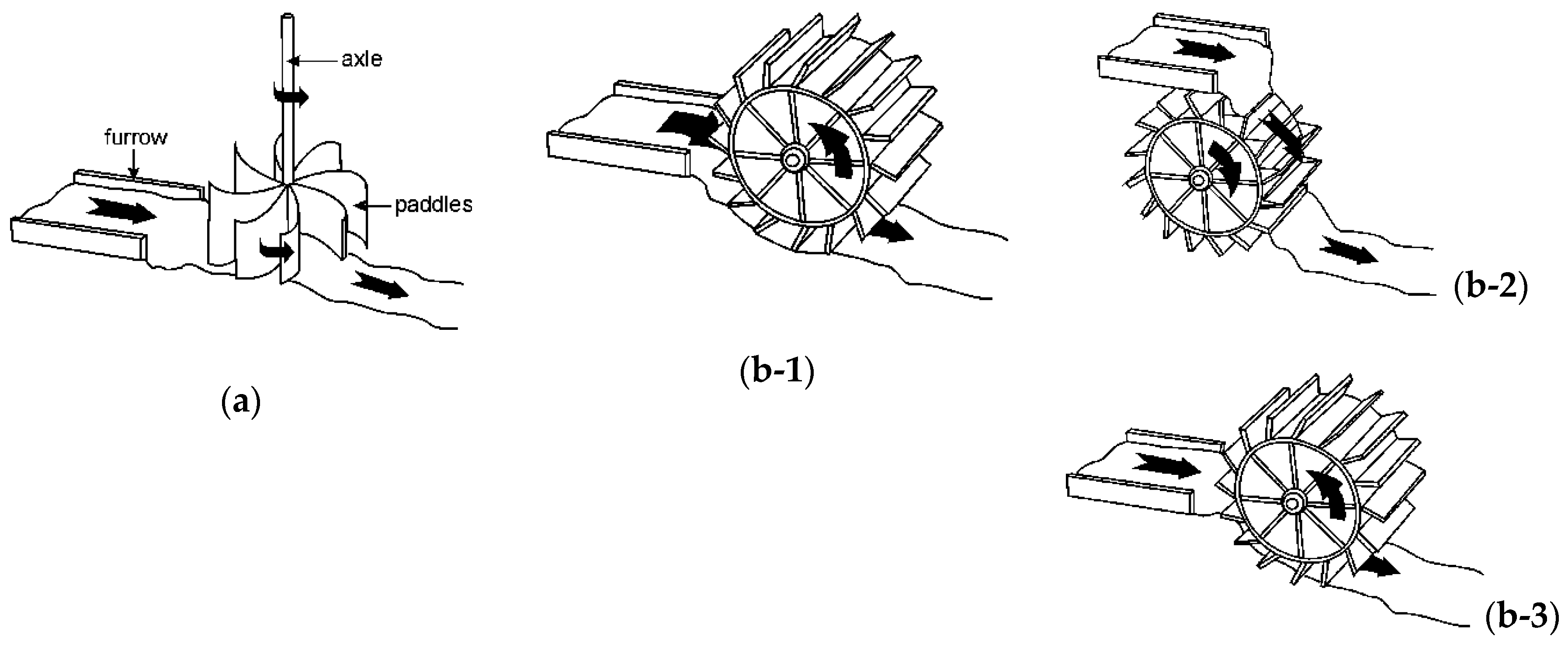
Quasi-static PressureWater wheel [32]
Sustainability 12 07352 i005
<10<5Vertical axis Water Wheels rotate due to the force exerted to the paddles by the momentum of the flow. Horizontal axis Water Wheels rotate because of the momentum of the water, as well as the weight of water on the small water buckets formed between the paddles. So, they are a bit more efficient than conventional horizontal ones [31]. The efficiency of well-constructed WWs is 50%–70% [31]. The hydraulic efficiency of Vertical Water Wheels is reported up to 85% [44].
Archimedes Screw
Sustainability 12 07352 i006
<10
[33,40]
<10
[33,45]
Efficiency range between 60% and 80% and remains high even as available head approaches zero. Produce up to 355 kW [46] of power [28]. Practical even in combined low head and low flow
Notes: * A Pelton turbine with flow 50 m3/s is a very extreme case; ** Micro-hydro impulse turbines sometimes operate with less than 50 m of head.

