Article

Multivariable Analysis of Transport Network Seismic Performance: Mexico City

by
Azucena Román-de la Sancha
1,* and
Rodolfo Silva
2
1
Engineering Graduate Program, National Autonomous University of Mexico, Mexico City 04510, Mexico
2
Institute of Engineering, National Autonomous University of Mexico, Mexico City 04510, Mexico
*
Author to whom correspondence should be addressed.
Sustainability 2020, 12(22), 9726; https://doi.org/10.3390/su12229726
Submission received: 14 October 2020 / Revised: 11 November 2020 / Accepted: 18 November 2020 / Published: 21 November 2020
(This article belongs to the Special Issue Project Intelligence and Management)

Abstract

:
In densely populated urban areas, predicting the post-earthquake performance of a transport network is a particularly challenging task that requires the integration of modeled structural seismic response, damage scenarios, and resulting traffic behavior. Previous approaches assessing the vulnerability and performance of networks after earthquakes have not succeeded in capturing and estimating the interdependencies between seismic risk parameters and key traffic behavior variables. This paper presents a methodology, based on data analysis and optimization, where the dynamic traffic modeling and probabilistic seismic hazard assessment are coupled, to link and characterize key network performance variables after extreme earthquakes and establish a multivariable seismic performance measure. The methodology is used to study the transport network in the southern part of Mexico City for a set of scenarios. The seismic environment is established through uniform hazard spectra derived for firm soil. Damage to structures is estimated considering site response and using fragility functions. Dynamic traffic modeling is developed to simulate damage-induced road closures and resulting in traffic variations. Post-earthquake network performance is evaluated through data envelopment analyses, obtaining sets of seismic performance boundaries, and seismic performance maps. The methodology offers a quantitative tool with applications in the planning of urban areas that are sustainable and seismic resilient.

1. Introduction

In highly populated urban regions, transport networks are considered critical infrastructure that should offer operational continuity both in normal and extreme conditions. However, the experience of past events, such as earthquakes and tsunamis in urban zones like Palu, Indonesia 2018 [1], Kaikoura, New Zealand 2016 [2,3,4], Central Italy 2016 [5,6,7], Kumamoto, Japan 2016, and Sendai, Japan 2011 [8,9,10,11,12], shows that during geo hazard events, urban networks are highly vulnerable, and the damage to elements of the network and nearby structures impacts the performance of these networks in both the short and mid-term, causing important social and economic losses. In urban environments, alterations to traffic conditions associated with damage to buildings and structures may immediately increase congestion and delays, which propagate in a wide zone and impact post-disaster rescue efforts and recovery activities. Forecasting the impacts on urban transport networks and their expected operational performance, after extreme seismic events, is a key process for planning sustainable and resilient urban areas.
Accurate modeling of transport network behavior in emergency scenarios is one of the most challenging tasks in urban planning. In major earthquake scenarios, for instance, the post-event performance of transport networks is related to expected damage scenarios. Determining these is complex as network components interdependences, the spatial variations of ground motions in a given region, and the specific response of structures must be considered. During a severe seismic event, traffic conditions are greatly influenced by the degree of structural damage. Road and transit networks have several components of varying structural characteristics (materials, structural system, number of stories), building codes used for design, and maintenance conditions, leading to a wide spectrum of damage after an earthquake. Urban transportation and mobility networks are also surrounded by numerous buildings with varying structural features. Moreover, these components and buildings are distributed in an area with heterogeneous soil profiles and diverse seismic wave propagation conditions. Additionally, in densely populated urban areas people have complex mobility patterns throughout the day, producing variations in travel demand and typical traffic phenomena, such as peak hours, congestion, queues, and pendula travel patterns.
The effects of seismic events on transportation infrastructure have generally been studied from a structural point of view, using seismic vulnerability approaches, which examine the susceptibility of structures to damage due to ground shaking. One of the most common approaches is that of fragility functions, that consist of assessing the probability of reaching or exceeding a given level of damage in a particular building, or structure, as a result of a specific seismic event. There are several studies available that analyze the seismic response of specific transport assets, such as bridges [13,14,15], tunnels [16,17,18], embankments [19,20,21], roads [16,22,23,24], and harbor elements [25,26,27]. However, transportation networks located in urban areas, interact with the built environment continually. Since earthquake damage in urban areas is mostly seen in buildings, research has generally tended to examine the existing building stock using empirical [28,29], and analytical models [30,31]. In all of these studies, the characterization of the ground motion is needed in order to correlate the seismic intensity parameters for the expected damage.
The vulnerability of transport networks during disruptions and emergency conditions has also been studied from other approaches. Some of these studies are based on network service functions, such as flow capacity [32,33], connectivity [34,35,36], and travel time [37]. Other works have focused on the associated traffic behavior during emergency events, using approaches such as mathematical optimization [38,39,40,41], fuzzy logic [42], and traffic modeling [43,44,45]. From a systemic standpoint, transport network vulnerability has been characterized by performance indicators that are usually designed to evaluate features such as connectivity, accessibility, and the level of service [46,47]. Some examples of studies that use systemic approaches are [48,49,50,51,52,53]. In these studies, the authors use simulation techniques to consider the spatial distribution of the seismic hazard, the vulnerability of the network components, and the interactions between roadway components and the built environment. Traffic behavior during emergency conditions has been evaluated using dynamic traffic assignment models, to optimize traffic signal operations during evacuation processes [54], to propose dynamic modeling frameworks to forecast changes in travel demand [55,56], and to benefit from information from intelligent transport systems to simulate emergency conditions [57]. One of the main challenges of this approach is the amount of data needed in development and calibration, the collection of which may be complex and costly. In addition, there is still a debate regarding the validity of demand data collected in the field during emergency scenarios [54].
Up to now, no works have considered modeling post-earthquake network performance and traffic behavior as a function of key seismological parameters such as ground accelerations and ground displacements. Under this perspective, the performance and vulnerability of the networks are understood as the response of traffic flow behavior to a given seismic intensity input. This paper presents a novel multivariable methodology to analyze the vulnerability and performance of urban transport networks in densely populated areas following strong earthquake scenarios, as a relation of seismic intensity and traffic behavior variables. The approach uses dynamic traffic modeling (DTA) combined with a multivariable efficiency approach, data envelopment analysis, (DEA). With this method, it is possible to consider time-varying post-earthquake flow distribution within the network and to identify the elements of the network susceptible to experience earthquake-induced travel time raise and velocity reduction. A new seismic performance indicator is introduced that evaluates network vulnerability as a function of both key seismological parameters (i.e., peak ground acceleration, spectral acceleration, and permanent displacements), and traffic behavior features (i.e., traffic volumes, travel times, and travel velocities).
First, a group of input and output variables is established. Then, detailed characterization of the area is required, as well as a number of analyses to obtain the input required for the model, including dynamic traffic modeling, probabilistic seismic hazard modeling, site response analysis, and seismic fragility curves. One of the purposes of the methodology, is to explore the influence of the spectral frequency of the earthquake on traffic, since earthquakes may induce different regional damage scenarios due to the energy concentration pattern. This depends on the source and fault mechanism of the earthquake. This methodology was applied to study the response and post-earthquake performance of a key sector of the transport network in the south of Mexico City. Seismic performance is evaluated through an efficiency value obtained for each segment of the network, referred to as a dual traffic seismic performance indicator (TSP index), which also describes the vulnerability of each segment after major earthquakes. A segment with efficiency equal to one will be expected to show high operational performance, while the lower the efficiency the greater the vulnerability of the element. Performance results are also expressed through a group of maps and curves denoted as seismic performance maps (SPM) and boundaries (SPB), the first ones are spatial distributions of all efficiency values, while the last is built using the elements with the highest values of efficiency.
The methodology introduces processes to forecast post-earthquake response and variations of traffic conditions in urban areas, and to establish a relation between the characteristics of the earthquake and the expected performance of the network.
Applications of the methodology could be in the planning, design, and monitoring of strategies to improve the sustainability and resilience of urban transport networks after an extreme earthquake.

2. Methodology

The methodology aims to predict the response of the transport network and to develop a new performance-vulnerability measure that predicts the expected behavior under given seismic conditions, it can be resumed in six steps:
  • Definition of input and output variables to define the TSP index for the network
  • Characterization of the urban area and selection of scenarios to be analyzed
  • Seismic hazard and structural seismic vulnerability assessment, including site response analyses.
  • Obtaining spatial distribution of damage and road closures scenarios, using geographic information systems techniques (GIS).
  • Modeling post-earthquake traffic behavior
  • Evaluation of network performance, through the TSP index, and development of SPM maps and SPB curves.
The methodology is shown in Figure 1 and further explained below.

2.1. Definition of Variables for the Multivariable Performance Model and TSP Index

To characterize the correlations between the network behavior and seismic characteristics, a multivariable performance model is proposed. The approach is based on the optimization model DEA.

Data Envelopment Analysis

DEA is a mathematical optimization model, used to evaluate the efficiency of systems and processes. Efficiency is understood to be a measure of productivity, where input variables, or resources, are used to obtain output or production. The main objective of the model is to evaluate the efficiency of a group of elements, or decision-making units (DMU). In the model, a set of input and output variables are used to characterize the DMUs, and an efficiency value is computed for each DMU. Using these values, it is possible to build an envelope curve or boundary, using the DMUs with efficiency values equal to one. The efficiency boundary is the maximum production of a given set of resources. Depending on the problem, the optimization model can be expressed as output-oriented or input-oriented. In the first, the outputs, or production, can be maximized, considering a fixed amount of resources, while the second case seeks to minimize the resources or inputs in order to obtain a given output. In a general form, the efficiency of a DMU group is obtained as a solution for the following problem, [58]:
M a x i m i z e h 0 = Θ 0 S u b j e c t t o k = 1 K λ k x i k = x i k 0 , k = 1 K λ k y j k = Θ 0 y j k 0 Θ 0 1 k = 1 K λ k = 1 , λ k 0 , i = 1 ,   ,   m ; j   =   1 ,   ,   n ; k   =   1 ,   ,   K
M i n i m i z e   =   S u b j e c t   t o :   k   =   1 K λ k x i k   =   θ 0 x i k 0     0     θ 0     1 , k   =   1 K λ k y j k   =   y j k 0 , k   =   1 K λ k   =   1 , λ k     0 , i   =   1 ,   ,   m ; j   =   1 ,   ,   n ; k   =   1 ,   ,   K .
where h0 is the efficiency of the DMU, k0 of the set of DMUs, K. Φ0 and θ0 are the efficiency factors of the output-oriented model (1), and the input-oriented model (2). The sub-index i corresponds to the m input variables, while j refers to the n outputs. In equation (2) λk denotes the weight of a reference virtual unit.
In this methodology, the model is used to determine the performance of urban transport networks, where segments are used as the elements defining the DMUs. A group of variables describing the earthquake and network features are considered as inputs, assuming that during an extreme seismic event, the network performance depends on characteristics such as the capacity-related features (i.e., length, velocity, and number of lanes) of the segments; as well as on seismic intensity parameters, such as peak ground and spectral accelerations. Then, variables that describe the travel behavior after the event, such as travel times or velocities, flows or traffic volumes, queue lengths, etc. describe the output of the system. Under these assumptions, applying an output-oriented approach, the segments with the best flow or traffic conditions, are identified, given the earthquake and network characteristics. An efficiency value of one, or perfect efficiency, is assigned then to them. The rest of the segments are compared to the perfect efficient DMUs and assigned corresponding efficiency scores. In this way, an efficiency value for each segment is obtained and denoted as the TSP index of the segment, expressing the seismic performance of the element. In this way, the TSP index of a transport network could be denoted as:
M a x   T S P i n d e x j   =   m   =   1 M u m j y m j n   =   1 N w n j x n j
where the TSP index of the segment j, is obtained as a function of the M outputs y, and the N inputs x, and the corresponding weights u and w, respectively. Table 1 presents input and output variables to model the performance and to obtain the TSP index of an urban road network. Given that this approach seeks to maximize the outputs, the inverse values of travel time and queue length are used in the performance model.
The TSP index for an urban road network would then be denoted as:
T S P i n d e x   =   f ( u 1 v ,   u 2 V , u 3 q , u 4 T t ) f ( w 1 l , w 2 L n , w 3 v 0 , w 4 P G A , w 5 S a 0.1 , w 6 S a 0.3 )
where v is the average velocity, V is the traffic volume, q is the queue length, and Tt the travel time, in the segment during the time interval analyzed. l is the length of the segment, Ln is the number of lanes, v0 the free flow velocity, PGA the peak ground acceleration, Sa0.1 and Sa0.3 the spectral accelerations at 0.1 and 0.3 s in the location of the segments. u1, u2, u3, u4, w1, w2, w3, w4, w5, and w6 are numerical parameters computed during the optimization process conducted with the DEA solution scheme.

2.2. Characterization of the Urban Area

The characterization of the area includes a detailed investigation of built and seismic environments, including the active seismic sources, buildings, transportation infrastructure, soil conditions, and dominant travel patterns in the zone.

2.2.1. The Seismic Environment

The prevailing seismicity of the study area is characterized by identifying all active earthquake sources, which could produce strong ground motions. Seismic activity can be recognized through ground motion records or through geologic and tectonic evidence. At this stage, source characterization considers the definition of the geometry or zones, and the distribution of magnitudes, and source-to-site distances of earthquakes from each source.

2.2.2. The Built Environment

A detailed survey, or database, regarding the building stock and strategic infrastructure in the study area, is required, complemented with historical data. The structural characteristics should include specific details on structural systems, material, number of stories, seismic design, ductility, foundation systems, age, and, where possible, details, such as building code and the state of maintenance. Data on the transport network should consider segment hierarchy, capacity, and velocity limits, as well as the locations of transition elements such as traffic lights and the corresponding cycle duration. The characterization of the built environment should consider grouping buildings and strategic infrastructure into typologies, examples of methods and common typologies can be found in [16,23].

2.2.3. Soil Conditions

In determining the geotechnical properties of the study area, possible differences in soil conditions within the zone must be considered. This can be done using previous geo seismic zoning or generic soil profiles, where data on the dynamic properties of the soil strata is available.

2.2.4. Travel Patterns

Characterization of the prevailing travel patterns in the area uses data sources such as origin-destination (OD) surveys, as well as data from traffic and public transport records. Information regarding peak hours and modal distribution is estimated to select the scenarios of interest to be later simulated, as well as convenient simulation periods and time intervals for the traffic model.

2.2.5. Scenarios Selection

The scenarios to be considered in the analysis are defined by the seismic environment and the travel patterns in the area. In this way, the seismic performance evaluation is recommended to be carried out for scenarios considering all active earthquake sources, return periods corresponding to extreme events, and peak travel demand hours. Off-peak hours conditions can be used to calibrate the traffic model.

2.3. Structural Seismic Vulnerability

2.3.1. Seismic Hazard

The seismicity of the area is established following conventional probabilistic seismic hazard analysis (PSHA). From this analysis, uniform hazard spectra (UHS) are generated, for different return periods. Separate UHS are obtained for each seismic source to examine the variations associated with the frequency content of the earthquake. In this way, hazard is determined for a set of possible seismic events.
The minimum steps for PSHA are:
  • Characterization of all seismic sources in terms of their probability of occurrence;
  • Selection, or development, of appropriate recurrence models, based on historical seismicity and available records, to estimate the rate at which a given event will be exceeded, for each seism genic zone;
  • Election of attenuation relationships, to estimate a set of seismic intensity parameters for the site;
  • Generation of seismic hazard curves;
  • Development of a UHS from the hazard curves for a given return period.
More details on the PSHA procedure can be found in [59].

2.3.2. Site Response Analysis

Once the UHS spectra are determined, and the geotechnical properties are established, by generic soil profiles, site effects are established through one dimensional SH wave propagation analyses. In cases where geological features do not have horizontally stratified soil deposits, a two dimensional, or even a three-dimensional wave propagation study should be required. This was not the case for this study. In order to take into account changes in the dynamic properties with cycle loading within soil deposits, in cases where soil nonlinearities are expected to be significant, time-domain analyses are required.

2.3.3. Fragility Curves

The probability of damage to structures in the study area is assessed using seismic fragility curves, which are functions that describe the probability that a structure exceeds a specific level of damage in response to a given seismic intensity value [49,60]. In these functions, seismic intensity can be characterized by parameters such as the spectral acceleration (Sa), spectral velocity (Sv), spectral displacement (Sd), peak ground acceleration (PGA), peak ground velocity (PGV), and permanent ground deformation (PGD). Fragility functions are commonly expressed as the lognormal cumulative distribution function (5):
F i ( P G A )   =   Φ ( l n ( P G A m i ) β )
where Φ is the standard cumulative distribution function, and mi and β are the median and the standard deviation of the log-normal distribution, respectively.
Various methods are currently available to define fragility curves, including judgmental (i.e., based on the opinions of experts), field observations, and advanced analysis using analytical and hybrid methods. However, analytical fragility curves have been shown to be more accurate than empirical or experimental curves. Numerous fragility functions are available in the literature for a wide range of building types and infrastructure. However, since design guidelines, structure types, construction methods, seismicity, and soil conditions differ around the world, some assumptions must be made in order to apply fragility functions in a general way. Taking into consideration all the different typologies of buildings and strategic infrastructure in the study area, a group of fragility functions is selected to determine the probabilities of damage for the different seismic scenarios.

2.3.4. Damage Probabilities

The probabilities of reaching or exceeding different levels of damage, i.e., slight, moderate, extensive, or collapse, for earthquakes associated with each of the previously obtained UHS, are determined using fragility curves for each building typology and transportation asset. The seismic intensity parameters are computed from site response analysis.

2.4. Damage Distribution

2.4.1. Spatial Distribution of Damage

The computed probabilities are mapped, using GIS-based spatial analysis techniques, to generate the spatial distribution of reaching a given state of damage within the area for each earthquake event. Probabilities can be mapped for each individual building, or for clusters of buildings, made by considering buildings in the same block, depending on the size of the study area, the data available, and the computing capabilities. In this way, sets of damage distribution maps are generated for each seismic event analyzed.

2.4.2. Segments Closure Criteria

Scenarios of post-disaster road blocking can be developed using methodologies based on the expected volume of debris caused by damage to the buildings, or on the joint probability of damage to buildings, bridges, and to ground failure [61,62]. Observations after the 2017 earthquake in Mexico City showed that in densely populated areas, short and mid-term road closures were enacted where immediate, moderate, and major damage to structures adjacent to roads was found, as safety procedures, ordered by the authorities.
Fieldwork coordinated by the Colegio de Ingenieros Civiles de Mexico (CICM), reported the earthquake caused 36 buildings to collapse, severely damaged 311, and moderate damage was found in another 958.
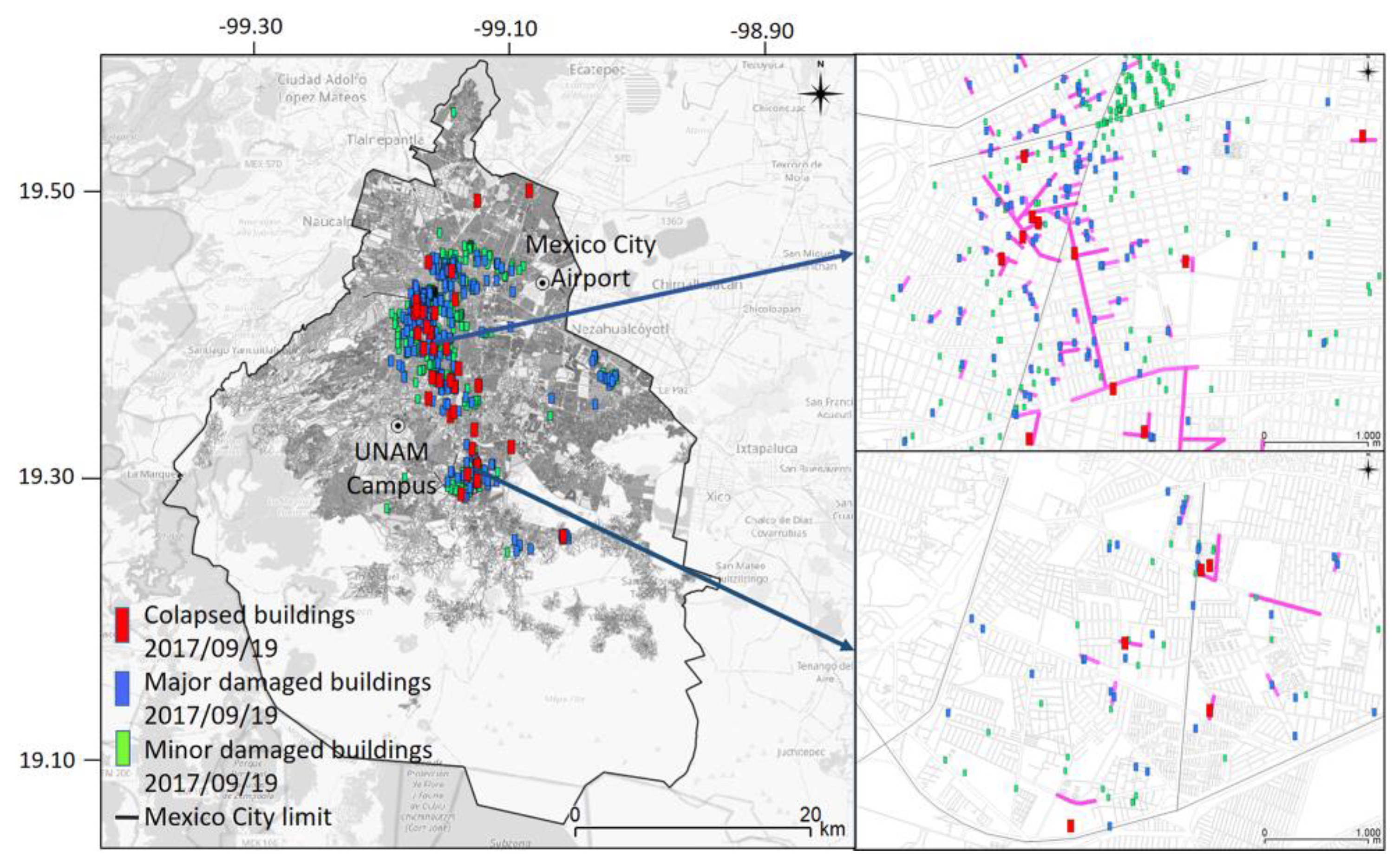
According to media reports, the safety policies of the city authorities closed 75 road segments. Roads near to all collapsed or severely damaged, buildings were immediately closed completely in the case of streets with two or fewer lanes, and partially closed in the case of roads with more than two lanes), examples of the damage pattern observed are presented [63,64]. Figure 2 shows some of the streets and avenues closed within two of the most affected areas in the city. Additionally, total and partial road closures were documented on road segments where there were buildings with moderate damage. In most cases, the roads were closed for 5–28 days for safety. For example, the five-lane highway, Viaducto Miguel Aleman, was partially closed near to where a six-story building had collapsed. Additionally, a two-story building on the five-lane Avenida Amsterdam had moderate damage, and a total road closure was reported. Similar closure patterns were observed in several other roads.
A relationship between the damage states considered in some fragility curves and the structural damage observed in buildings for the earthquake in Mexico City in 2017 was identified by [65]. Considering those relations and the observed closure pattern, a new criterion for road closure was adopted for this research, which can be replicated in densely populated urban areas, where safety policies following major earthquakes are applied. The criterion considers that a total closure of roads with two lanes or less, and the partial closure of roads with more than two lanes will occur near buildings likely to reach moderate or major damage.

2.5. Post-Earthquake Traffic Model

2.5.1. Traffic Model

Traffic response is simulated using a dynamic traffic assignment model to characterize traffic behavior resulting from seismic-induced disruptions in the road network. DTA modeling implies determining time-dependent path choices in a network given time-varying demands. From the seminal work of [66,67,68], traffic assignment modeling approaches have evolved to cutting-edge methods, where real-time traffic information and ITS are used to forecast behavior and route choices more accurately with extensive application purposes [69,70,71]. Traffic assignment models allow the study of traffic flow phenomena from different levels of detail and temporal approach, mainly using microscopic, mesoscopic, and macroscopic models, under either static or dynamic conditions. Assumptions for the development of traffic assignment models may include Wardrop’s user equilibrium principle [72] and/or stochastic methods to determine the route choices and flow distribution within the network [73].
In general, DTA models consist of a demand model, a network model, and a group of impact models. The demand model contains travel demand data. The network model contains a group of traffic zones representing the origin and the destination of trips and a set of nodes and links representing roads and railway tracks. DTA models can be classified into analytical and simulation-based. The first ones either use variations of static user equilibrium principle or system optimal objectives, while the latter develop iterations between three elements: a traffic simulation module, a shortest path module, and a network-loading module [66]. DTA approaches are convenient to capture dynamics prevailing in urban zones, where traffic conditions often vary in short intervals of time. Traffic and transport behavior are characterized by traffic volumes, travel times, queues, and velocities reached in the segments and obtained from the model. More information regarding the fundamentals of traffic modeling and DTA models can be found in [73,74,75,76].

2.5.2. Calibration of Traffic Model

DTA models are usually calibrated using data from traffic information systems or traffic counts obtained in the field. The general process is well described in [77] and includes the empirical data required, the observation of discrepancies between empirical data and the model output, and the analysis and correction actions of these differences.

2.5.3. Traffic Modelling of Earthquake Scenarios

Once the traffic model is calibrated, the selected seismic scenarios are simulated considering the expected partial and total segments closures. The DTA model can include either the road transport network, or the public transport networks, or both, depending on the computational capabilities and the availability of data. Furthermore, some DTA models allow the integration of dynamic OD matrixes, which enhances the accuracy of the model outputs. However, considering changes in post-disaster travel patterns is still challenging, since data regarding post-earthquake mobility patterns is generally non-existent. It is also cumbersome to estimate since surveys or records regarding expected patterns or preferences after seismic emergencies are scarce. The increase in the use of information and communication technologies in urban areas has provided extra data regarding mobility trends in recent seismic events, which could be useful for future modeling.

2.6. Multivariable Network Performance Model

To correlate traffic behavior response to the seismological characteristics of the event, the seismic network performance model is applied. For each scenario, an efficiency value is obtained per DMU or segment. The set of performance values can be expressed in two forms: in a graphic form as a group of performance boundaries, and spatially as a group of seismic performance maps.

Seismic Performance Boundaries

Using the TSP index results from the performance model, a set of curves SPB is derived. First, DMU or segments with TSP index values equal to one are identified. Then, the output and input values corresponding to those DMUs are related and plotted. The resulting curves create an envelope or performance boundary, where the segments with the best characteristics and conditions to face earthquake-induced traffic behavior envelop the vulnerability of the segments, Figure 3. These curves are used to identify and compare the characteristics of the elements of the network that exhibit the best performance during different earthquakes.

3. Case Study: Mexico City Road Network

3.1. Characterization of the Urban Area

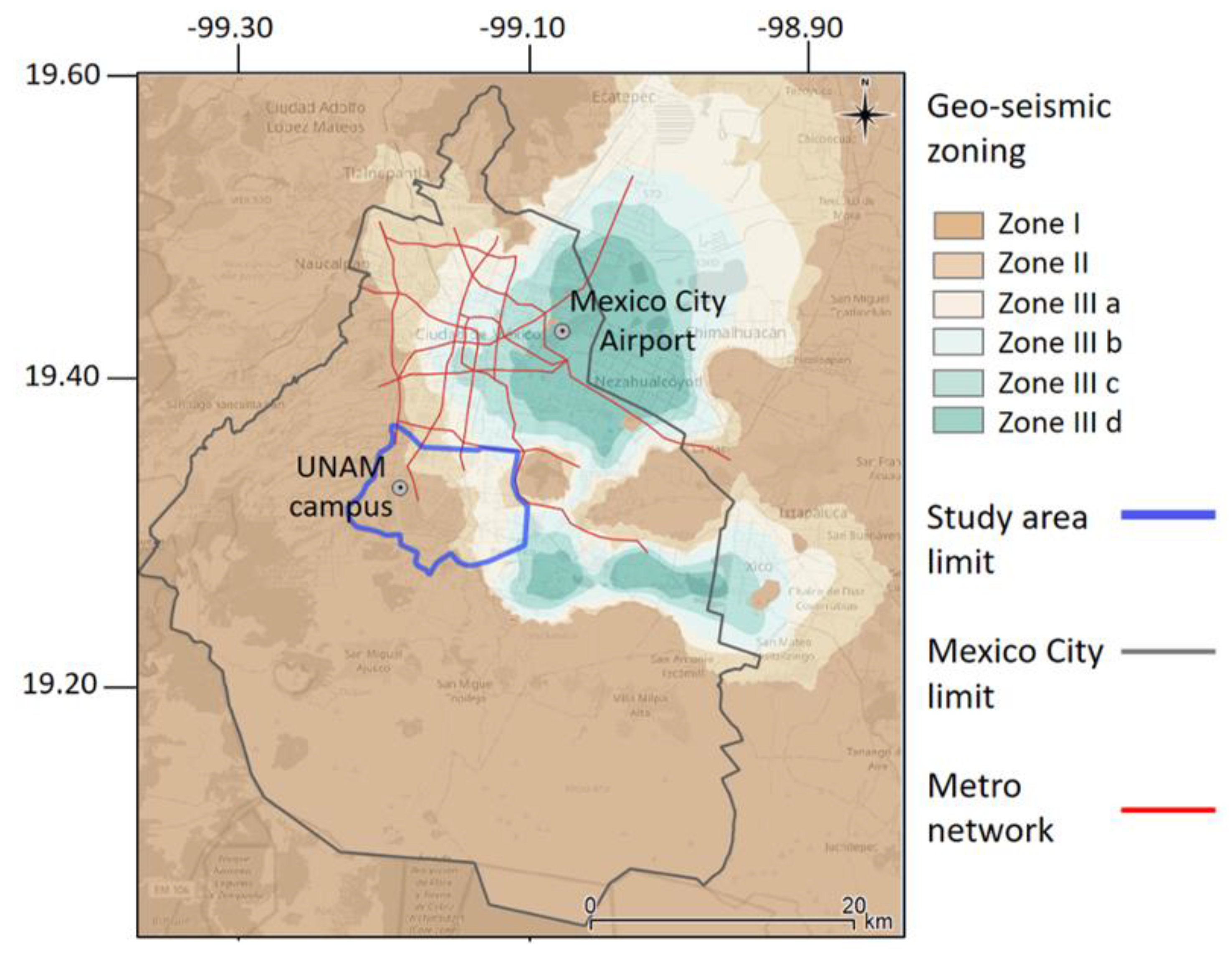
Mexico City and its metropolitan area, with more than 22 million people, is the core of one of the most densely populated urban regions in the world, at around 6000 people per km2. Located in the basin of two former lakes, the city is vulnerable to subduction earthquakes originating in the southwest Mexican Pacific and normal fault mechanisms from within the continent. Soil conditions result in irregular seismic wave propagation patterns in some areas. Wave amplification phenomena associated with the high plasticity clay found in these former lakes is also a threat to buildings in the city and surrounding area. Disruptions in transportation infrastructure following earthquakes are also likely. Despite the robust public transport and road networks, the region is one of the most congested in the world. It is estimated that every day around 18 million trips are made within the Mexico City metropolitan area, using public and private transportation [78]. An area in the south of Mexico City Figure 4, was used in the case study for the application of the methodology presented in this paper.

3.1.1. Seismic Environment

Mexico City is located in a region prone to strong earthquakes. Historically, subduction and normal fault earthquakes have been the ones that have caused the greatest damage to structures. The maximum magnitude recorded since 1800 is Mw = 8.4 during the Jalisco earthquake, however, the earthquakes from the Guerrero and Michoacán coasts are the ones that have produced the most violent movements in the valley, such as the devastating 1985 Michoacán earthquake. Likewise, significant damage can be expected to be caused by normal fault earthquakes such as the 2017 Mexico City-Puebla earthquake.

3.1.2. Built Environment

The building stock in the study area is a mix of residential and commercial structures that ranges from 1 to 37 stories. Buildings from 1 to 3 stories, 91.5% of the stock, are mostly reinforced masonry structures, while buildings of 4 to 10 stories, 8% of the stock, are mostly made from reinforced concrete frames. The material used in buildings of 11 stories and more, 0.5% of the stock, consists mostly of either reinforced concrete frames or a mix of steel and reinforced concrete. In total, 45,500 buildings were considered and then grouped into 2180 blocks, according to the clustering criterion from the last household OD travel survey in the city [78].
From fieldwork, the urban transportation infrastructure in the area was identified, as shown in Figure 5. This consists of 48 urban bridges, 5 tunnels, and 148 km of urban roads, as well as 18 bus rapid transit (BRT) stations, 12 metro stations, 10 light rail stations, 14.5 km of metro tracks, and 9 km of light rail tracks. Buildings and infrastructure found in this area were classified and integrated into a geographic information system using the typologies presented in Table 2.

3.1.3. Subsoil Conditions

Since the devastating 1985 earthquake, subsoil conditions have been the subject of several research projects in Mexico City, and are therefore reasonably well-documented. The city is located on the site of two former lakes, drained from 1530: Lakes Xochimilco-Chalco and Texcoco. The western part of the city is built on top of rock and hard soil deposits, while the eastern part lies on soft, layers of clay [79]. The high plasticity clays under Mexico City exhibit a nearly elastic response for medium to large shear strains, which can lead to high amplification of seismic waves.
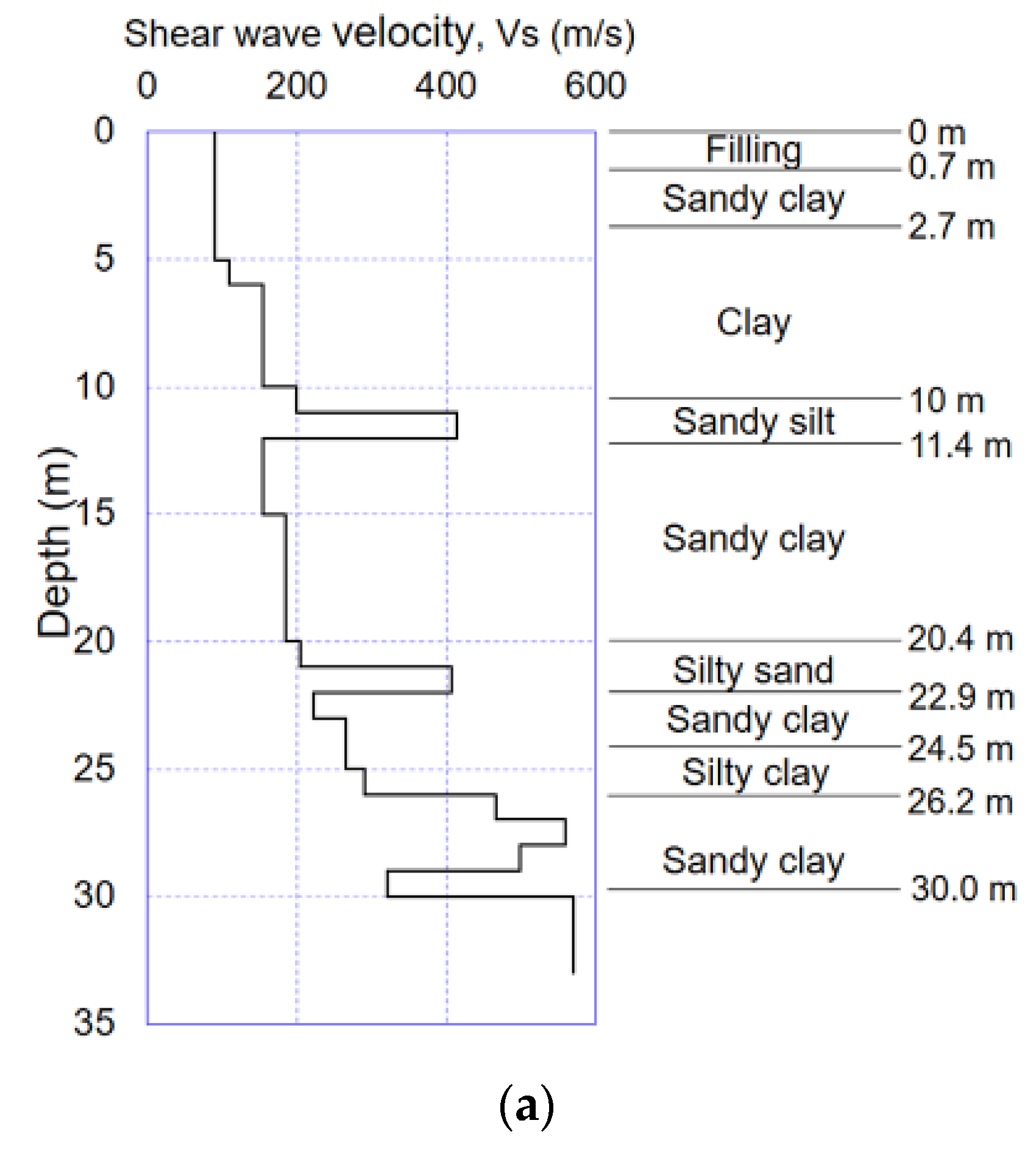
As shown in Figure 4, there are three distinct zones in the study area according to the Mexico City building code [80]. In Zone I (Hills), there are mainly firm soils and rocks; in Zone II (Transition), the deposits of silty sand and sandy silt layers, up to 20 m deep, are usually combined with layers of lacustrine clay; Zone III (Lake) has deposits containing highly compressible clay, interbedded by sandy layers of varying silt or clay contents. In the Lake Zone, the depth of the clay deposits increases from the hill zones towards the center of the former lakes, so Zone III is divided into IIIa, IIIb, IIIc, and IIId, see Figure 4. The corresponding soil conditions in the study area were characterized using the generic soil profiles, which are representative soil stratigraphy for each zone studied, derived from field exploration and reported in [81,82,83,84] Figure 6.

3.1.4. Travel Patterns

Prevailing travel patterns for weekdays in the area and demand data for the traffic model were determined from the 2017 household travel survey of Mexico City [78] and from traffic counts and drone-video recordings conducted at some segments and intersections within the study area. Three peak hours were identified, 7:15–8:14 a.m., 12:30–13:29, and 18:45–19:44 h, the first period having the highest number of trips, Figure 7. Modal distribution in weekday morning peak hour is generally made up of 37% public transportation, 27% private, and 36% walking and bicycle. Trips on public transport are made by buses (70%), Metro (20%), taxi (8%), and other modes (2%), such as rapid transit bus, BRT, and a light railway. In Mexico City, 70% of public transport trips are made using low capacity vehicles that do not have a regular, schedule-based or frequency-based, scheme of operation. These services operate without fixed stops, schedules, or frequencies. Moreover, at the time the model was conducted there was no official database regarding fixed routes of this kind of service. However, the presence of mini buses and low capacity public transport vehicles on the road network was taken into account, considering a proportional number of vehicles as part of the traffic flow, and the occupation according to a corresponding number of trips.

3.2. Structural Seismic Vulnerability

3.2.1. Seismic Hazard

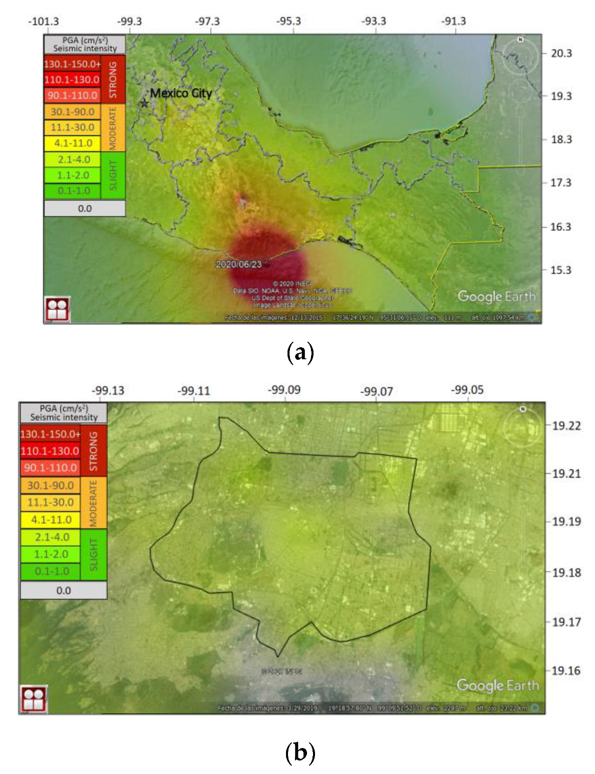
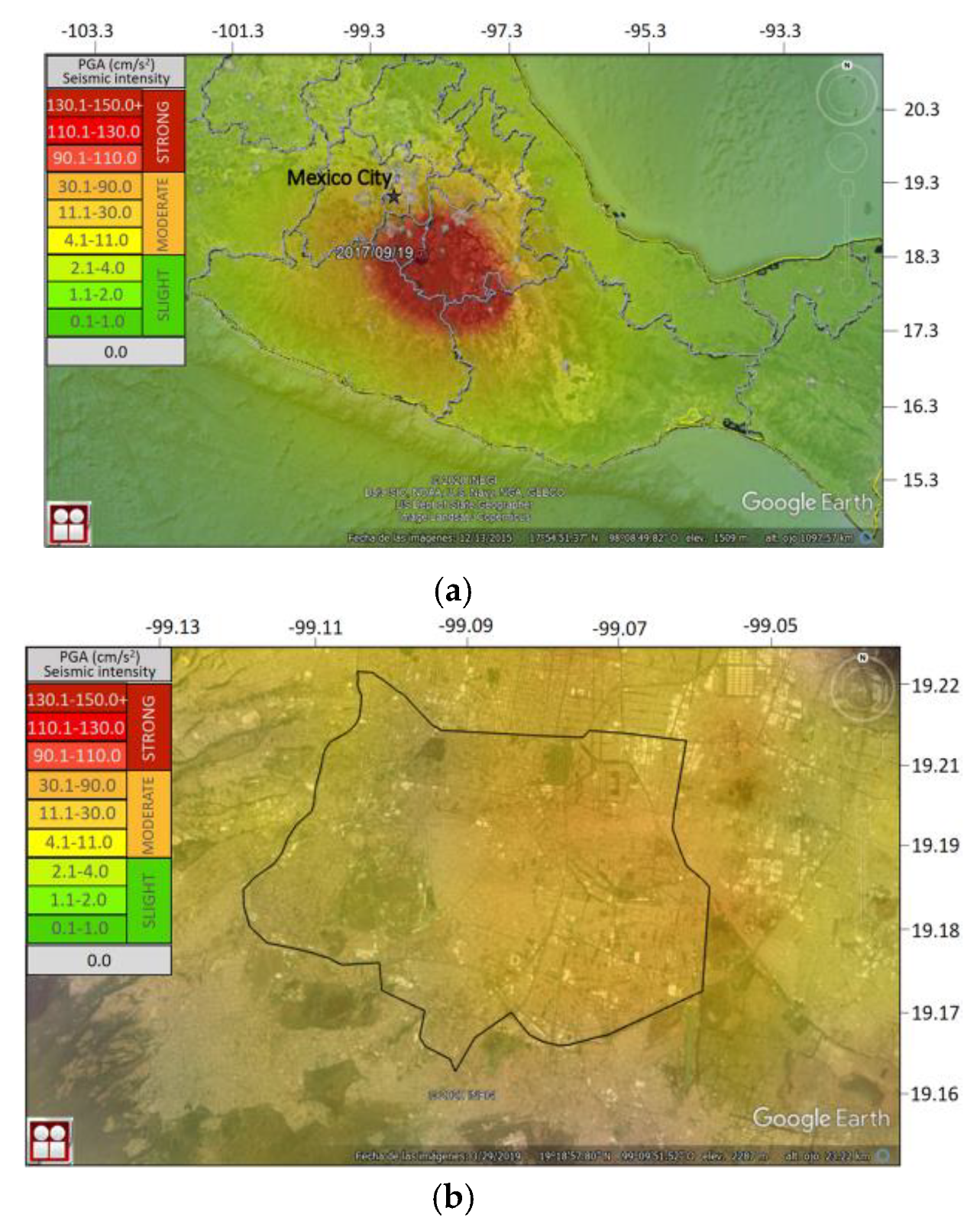
The size of the study area is small, compared to the distance between this and the areas of energy release of the two seismogenic zones considered. In Figure 8 and Figure 9 the shake maps obtained by the Institute of Engineering and the Serivicio Sismológico Nacional for two recent events and a zoom of the study area are presented, [85]. Under this assumption, the seismic risk was calculated in the study area following PSHA steps, [59]. The uniform hazard spectra derived for a rock outcrop in Ciudad Universitaria, UNAM, nearby, was used to characterize the seismic environment. Eight scenarios were considered, with four return periods, Tr, of 125, 250, 475, 2475 years, for both subduction and normal events, Figure 10. The UHS for Tr = 125 years is compatible with the 2004 Mexico City building code [80], while the UHS for Tr = 250 years corresponds to the most recent building code [86]. Return periods of Tr = 475 years and Tr = 2475 years are internationally accepted for the seismic design of strategic infrastructure. The variations in local seismic intensity expected over the study area are low, as shown in shake maps from past events, Figure 8 and Figure 9. Thus, the use of generic soil profiles to characterize soil conditions over the study area was considered appropriate.

3.2.2. Site Response Analysis

To estimate the ground amplification for each of the uniform hazard spectra presented in Figure 10 at Zones II, IIIa, and IIIb, one-dimensional wave propagation analyses were carried out in Figure 6, using the RADSH program [87]. The seismic response of each generic soil profile was obtained using random vibration theory.
The algorithm employed to compute the probabilistic site response of horizontally stratified soil deposits, subject to two-dimensional SH waves, propagating vertically is described in [88]. The input motion is defined in terms of a response spectrum, from which an equivalent power spectrum of the seismic ground motion is computed. Using the random vibration theory, the maximum responses of a linear system excited by a stochastic process is computed for a given confidence level. Thus, the uniform hazard spectra computed for each return period were used directly as input.
To establish the corresponding permanent displacements, time-domain analyses were carried out using three-dimensional soil columns, Figure 11, for each generic soil profile shown in Figure 6. These were simulated with finite difference models, which were developed using the software Fast Lagrangian Analysis of Continua (FLAC) [89].
The seed time histories depicted in Figure 12 correspond to the ground motions recorded at the seismic station in Ciudad Universitaria for the two earthquakes (19/09/17 and 19/09/85). A seed ground motion is an accelerogram recorded on firm soil or rock during an earthquake of large magnitude occurring in a given seismogenic zone. This seed motion is further modified in the time-domain to match specific response spectra. Thus, they were adjusted to the uniform hazard spectra that define the seismic environment for each return period, using the method proposed by [90], as modified by [91]. The seismic parameters of these earthquakes are presented in Table 3.
For each return period (125, 250, 475, and 2475 years), and seismogenic zone (subduction and normal), the acceleration time histories were deconvolved and applied at the base of the finite difference model shown in Figure 11. As described in [92], the code SHAKE [93] was used in the deconvolution process. A number of constitutive models have been developed to consider soil nonlinearities [94,95,96], however, the absence of experimental data has precluded the development and calibration of a reliable constitutive model for the high plasticity clays of Mexico City. Thus, to properly deal with both modulus stiffness degradation and damping variation, during earthquakes, the hysteretic model included in FLAC3D, called “sig3″, was applied. This model has been successfully used in the past by other authors to predict measured seismic responses at instrumented sites in Mexico City [97,98]. In the model, an ideal hypothetical soil is considered, where the stress is a function of the deformation and not of the number of cycles of seismic loading. An incremental constitutive relationship of the degradation curve is expressed as τn/γ = G/Gmax, where τn is the normalized shear stress, γ is the shear strain, and G/Gmax the normalized secant modulus. The sig3 model is then:
G G m a x   =   a 1   +   e x p ( L x 0 b )
where L is the logarithmic strain defined as L = log10(γ).
An iterative fitting approach was applied to the modulus degradation curves and the model equations to obtain the parameters a, b, and x0. The corresponding damping is given directly by the hysteresis loop during cyclic loading. For the cases modeled in this research, the parameters “a”, “b”, and x0 vary from 1.00 to 1.02, −0.46 to −0.55, and −1.50 to 0.20 respectively. As pointed by [99] nonlinear soil behavior depends on the shaking level, which, if high, leads to degradation of shear stiffness and an increase in damping.
As pointed out in [79,92], the increase in damping at high strains in the FLAC3D model is due to a limitation of hysteretic-type models, which are not able to entirely capture both shear stiffness degradation and damping curves developed under steady-state conditions simultaneously. Still, in a nonlinear analysis, the characterization of ground response in each loading cycle is a function of the evolution of shear strains during ground shaking, rather than the steady-state response obtained experimentally.
Figure 13 shows the modulus degradation and damping curves used in the stochastic site response analyses, along with the corresponding fitting curves for the time-domain analyses conducted with FLAC3D. These curves were deemed appropriate, as they have been used successfully to simulate the seismic behavior of the silty sands and sandy silts found in Mexico City by other researchers [75,79,82,92,99].
Figure 14, Figure 15 and Figure 16 show the response spectra computed for Zones II, IIIa, and IIIb, respectively, for normal and subduction events. The results for both the frequency and time-domain analyses are included in these figures. There is good agreement between the computed responses and both approaches.
As previously mentioned, RADSH analyses are stochastic. They account for an infinite number of acceleration time histories, with the same mean frequency content but with randomly distributed phases. Meanwhile, the results obtained with FLAC are deterministic and specific to the time histories considered, which are related to ground motions recorded in Mexico City, during the 1985 and the 2017 earthquakes, which are the strongest events that have struck the city in recent years.
Considering that the subsoil conditions in Zone I are associated with rock and stiff sandy silts or silty sands, it was assumed that the control uniform hazard spectra shown in Figure 12, is a good estimation of the expected ground motions in this area for practical purposes. Peak ground acceleration (i.e., Sa at period, T, equal 0 s) and permanent ground displacements for each seismic scenario were obtained based on the results of seismic response analysis. Spectral acceleration at 0.1 s and 0.3 s were also determined, as shown in Table 4, Table 5, Table 6 and Table 7. The spectral values needed in the fragility study were obtained using the stochastic approach, and it was considered that they correspond to an infinite number of input motions.
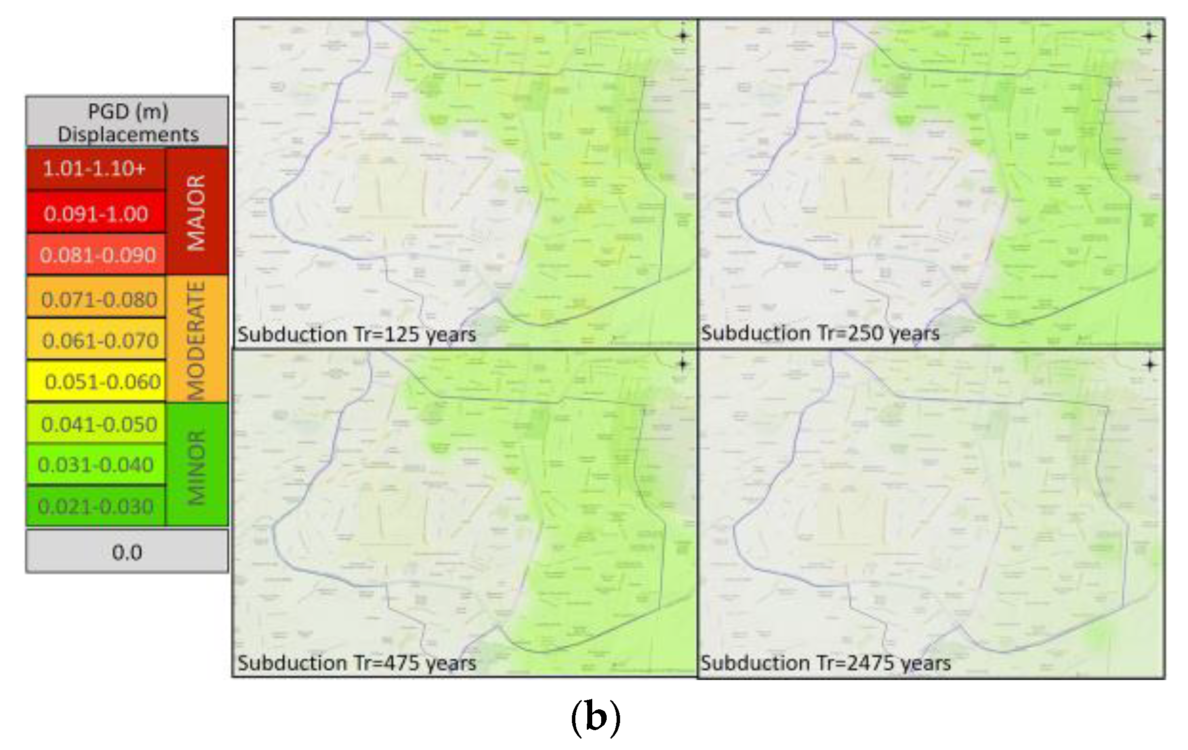
Using the values obtained for each seismic scenario, an approximation of the spatial distribution of the accelerations and displacements over the area was made, using the inverse distance interpolation method, Figure 17 and Figure 18.

3.2.3. Fragility Curves

Fragility curves for existing building stock and for transport infrastructure in Latin America can be found in [18,103,104,105,106,107]. These curves are based on nonlinear time history analysis (NLTHA) and were developed to predict damage to buildings and structures, such as reinforced concrete bridges, underground structures, and urban overpasses.
The analytical fragility curves, presented in Table 8, were selected to determine the probability of damage to structures in the study area. The damage prediction capabilities of these functions were assessed after the 2017 Mexico City earthquake [65]. However, the authors recognize there is still a degree of uncertainty related to the site-particular assumptions inherent in the fragility functions selected for the analyses.

3.2.4. Damage Probabilities

The probability of reaching or exceeding different damage states was estimated using the intensity parameters obtained from the previous numerical analysis. According to the fragility curves considered, the damage is probable in the study area only to buildings. The probability of reaching any kind of damage state to bridges, tunnels, and railway tracks is as low as 0.01% for all the scenarios studied.

3.3. Damage Scenarios

3.3.1. Spatial Distribution of Damage States

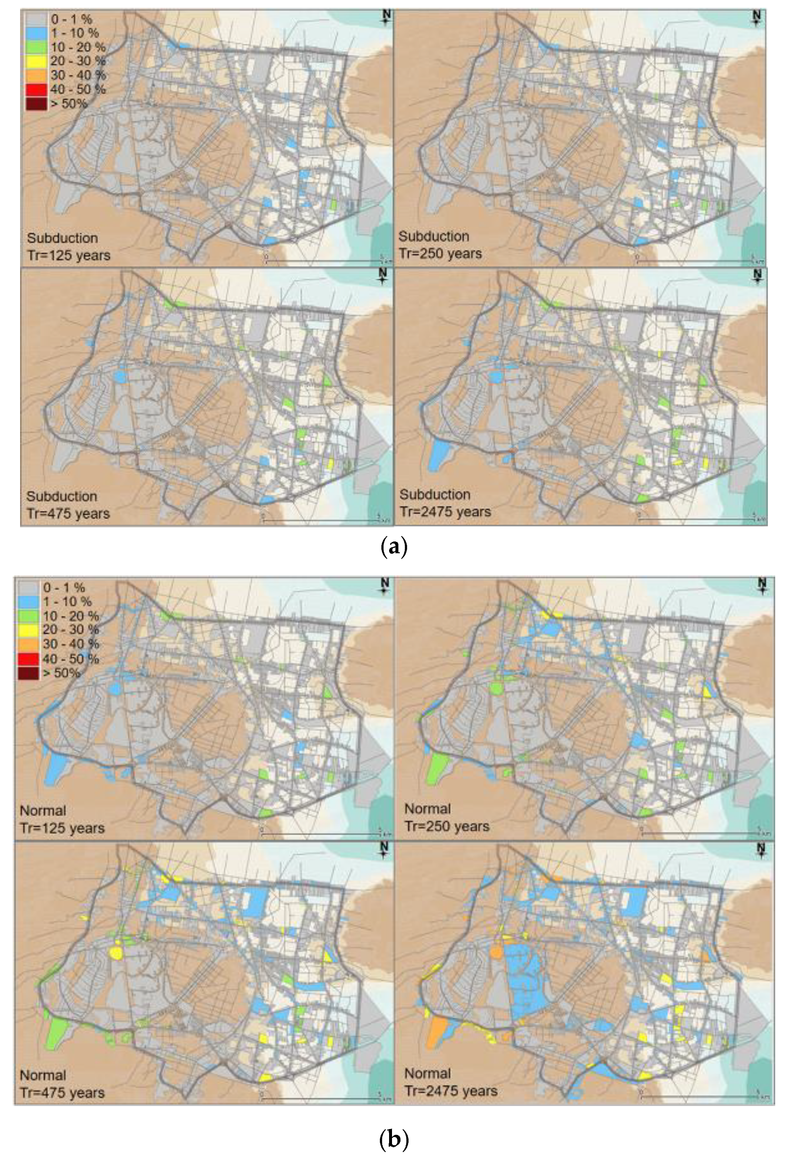
The probability of reaching different damage states obtained for buildings, computed directly from fragility curves, was processed in a GIS model to generate a spatial distribution for eight different scenarios: Tr = 125, 250, 475, and 2475 years both for normal fault and for subduction events.
For subduction events, the probability of reaching a moderate damage state was below 20% for most of the blocks for events of Tr = 250 years and Tr = 475 years. This probability rises for events of Tr = 2475 years in buildings located in Zones IIIa and IIIb. For the same events, the probability of reaching a major damage state is expected in few blocks located in Zone IIIb, while for Tr = 2475 years, this probability rises to over 20% for the same structures and extends to Zone IIIa. In the case of normal fault events Tr = 250 years, the probability of reaching moderate damage is as high as 50% in a number of building blocks located in Zone II, and 40% in those in Zone IIIa. For normal fault scenarios Tr = 475, the probability of reaching moderate damage increases to more than 50% in blocks placed in Zone II, while for Tr = 2475 years reaching moderate damage is more than 50% probable in several blocks located in Zones II, IIIa and IIIb. Reaching extensive damage states during normal fault scenarios Tr = 250 and 475 years is less than 20% probable only on some blocks located in Zone II, while for Tr = 2475 years that probability becomes more than 40%. Figure 19 shows the maps of the distributions of the average probability of damage states (i.e., slight, moderate, major, and collapse) for buildings, for subduction and normal events.

3.3.2. Road Closure Criteria

Following the observations of the 2017 earthquake, the road closure criterion adopted in this study considers that a total closure of roads with two or fewer lanes, and a partial closure of roads with more than two lanes will occur near buildings with a probability of experience moderate and extensive damage. Figure 20 shows the road segments affected for normal and subduction scenarios in different return periods.

3.4. Dynamic Traffic Modelling

The simulation-based dynamic assignment model included in the VISUM code [109] was employed to simulate the post-earthquake road network behavior. This model was developed using the algorithms presented by Mahut in [110], blending macroscopic and mesoscopic methods, incorporating a simulated car-following model to have the vehicles follow the paths in the network. The traffic model in the present research considered only the macroscopic simulation approach. The applied simulation-based model takes into account the network topology, the dynamics of travel demand, and a car-following model. The model performs an iterative dynamic user-equilibrium traffic assignment process, giving outputs such as routing options and varying travel times. As defined in [110,111], in the space of path flows hk(t), for all paths k belonging to the set Ki, for an origin-destination i ∈ I, at time t, the dynamic equilibrium problem can be expressed as:
Ω   =   h ( t ) :   k K i h k ( t )   =   g i ( t ) ,   i     I ; h k ( t )     0   f o r   a l m o s t   a l l   t     T d
where path flow rates in the feasible region Ω satisfy the conservation of flow and non-negativity constraints for t ∈ Td, the period defining temporal demands is (0, Td) and gi(t) are the time-varying demands. Then, if the dynamic version of the static user equilibrium conditions (Wardrop) where hk ∈ Ω, is defined by,
s k ( t )   =   u i ( t )   i f   h k ( t )   >   0 s k ( t )     u i ( t )   o t h e r w i s e f o r   a l l : k     K i ,   i     I   f o r   a l m o s t   a l l   t     T d
ui(t) = mink∈Ki{sk(t)} for almost all t ∈ Td and sk(t) is the path travel time determined in the dynamic network loading. The solution for solving the continuous-time problem in (7) and (8), the network loading scheme and the simulation approach, are described in detail in [110,111]. More specifics regarding the assignment approach and algorithm in VISUM can be found in [109,110]. The traffic model allows time-dependent OD matrixes to be generated for each time interval. This process was carried out in the study by adjusting the initial OD matrix with traffic counts obtained at some of the segments. In this way, the dynamics of travel demand within the simulation period was considered.

3.4.1. Calibration of Traffic Model

Calibration was conducted using traffic counts and drone-video recordings obtained in the field at some segments and intersections for a morning scenario, in both off-peak traffic conditions, 5:00–6:00 a.m., and peak-hour 7:15–8:15 a.m. The authors are aware of the limitation of the model, associated with the lack of a larger traffic database, however, it is hoped that research such as this, will stimulate the local technical and scientific community, to conduct further research to generate these data in places like Mexico City. The traffic model considers a network of 23 traffic zones, 782 nodes, and 2354 links, representing major and urban roads within the area. It was calibrated using the traffic volumes and velocities obtained in the field, which were fed into the model to adjust the route choice model. Ten segments were used as control elements for the calibration process, where traffic counts and drone-video recording were conducted periodically on 10 Wednesdays, at the same hour and interval. From the fieldwork carried out, the average values of velocities, travel times, and traffic volumes were obtained. A correlation coefficient value was computed every time the model was updated with new field data, comparing measured and modeled values for travel times, traffic volumes, and average velocities. Correlation values corresponding to the first and final traffic models are presented in Table 9. Figure 21a–c depict the correlation curves for some of the control segments.

3.4.2. Earthquake Scenario Modelling

The morning peak hour, from 7:15 to 8:14 a.m., was selected to evaluate impacts in the traffic conditions in the study area. First, to reproduce typical traffic conditions, the calibrated traffic model was loaded with the travel demand of the road network for a 1-h simulation period, and a 2-h preloading and a 2-h unloading period.
Trips were considered to follow the same origins and destinations after each event, due to the lack of an accurate estimation of post-earthquake changes in travel patterns. Traffic flow distribution and parameters such as travel times, velocities, and queue formation were obtained for 10 min intervals. For the case study, three post-earthquake traffic scenarios were simulated, the subduction event Tr = 475 years and two normal earthquakes Tr = 475 years and Tr = 2475 years. In this way, impacts in traffic behavior between normal and subduction earthquakes were compared.
Figure 22, illustrates travel times for seismic scenarios of Tr = 475 years for normal fault and subduction events. In those scenarios, the traffic volumes increased in the road segments around closure, which produced an increase in travel times and queue lengths, as shown in Table 10.

3.5. Multivariable Performance Evaluation and TSP Index

Based on the values from site response analysis and traffic simulations, seismic performance evaluation of the network was conducted for three scenarios. First, normal earthquake scenarios for two return periods Tr = 475 years and Tr = 2475 years were chosen to determine the influence of earthquake magnitude on traffic behavior. A second comparison was made with normal and subduction earthquake scenarios, both with Tr = 475 years, to examine the effect of the spectral frequency of the earthquake on traffic evolution. The DEA approach, described previously, was applied to evaluate the performance of each road segment of the network, using the variables presented in Table 1. The code MaxDEA [112] was used to conduct the analyses.

3.5.1. Seismic Performance Maps, SPM

The efficiency values obtained for the network in typical traffic conditions, and the TSP index values for normal fault earthquakes Tr = 475 years and Tr = 2475 years, and a subduction earthquake Tr = 475 years are presented as corresponding seismic performance maps in Figure 23. In these maps, the segments with lower TSP index values match those with an increase in travel time and a reduction in velocity in the traffic models.
Some differences were observed in the response of the network depending on the geotechnical location of the segments. Road segments located in soft soil, such as Zones IIIa and IIIb, were found to operate less efficiently for both normal and subduction earthquakes, while roads in Zones I and Zone II are expected to operate with an efficiency of over 80%. This result is predictable in terms of site responses since high amplification and damage are expected in soft soils. However, low efficiencies were also found associated with characteristics of the network design, such as the capacity of the segments and the traffic control systems at intersections, Figure 23. The lowest TSP index values were obtained in low capacity segments (1 or 2 lanes), in the soft soil areas. In these areas, there are very few high capacity segments, most of the intersections are controlled by traffic signals and there are few bridges or overpasses to facilitate continuous traffic flows. Hence, a combined effect, of the expected site response and the network design, was found to influence performance after a major earthquake scenario. On the other hand, high TSP index values were obtained mostly for segments in Zone I. In this area, no ground motion amplifications are expected and therefore most structures will show better seismic behavior. Furthermore, the road network in Zone I has a greater number of high capacity roads, bridges, overpasses, and interchanges that enable traffic to flow smoothly.
Findings show a strong dependency on the transport network performance on the frequency content of the earthquake, which is directly associated with the seismogenic mechanism (i.e., normal fault or subduction). This is clear when comparing seismic performance maps for normal and subduction earthquakes for the same return period, Tr = 475 years. In the first case, the performance is affected over a wider area, whereas in the second, the number of segments affected is smaller, but the TSP index reduction is more significant. The influence of earthquake magnitude was also registered in the performance model, as observed in the maps for normal earthquakes Tr = 475 years and Tr = 2475 years, Figure 23. In both cases, the impacts are focused on the same locations and segments. However, in the case of the Tr = 2475 years event, the reduction in the TSP index is larger.

3.5.2. Seismic Performance Boundaries, SPB

A set of curves, or Seismic Performance Boundaries (SPB), were developed, relating the corresponding input and output values of the DMU with TPS index equal to 1 for each scenario analyzed. These relations were also confirmed through the estimation of the correlation coefficients R2 presented in Table 11. From these values, in the case of normal fault events, the strongest correlation was identified between spectral accelerations, Sa, and capacity, velocity, and travel time. For subduction earthquakes, there was a high correlation between peak ground and spectral acceleration with velocity and traffic volumes.
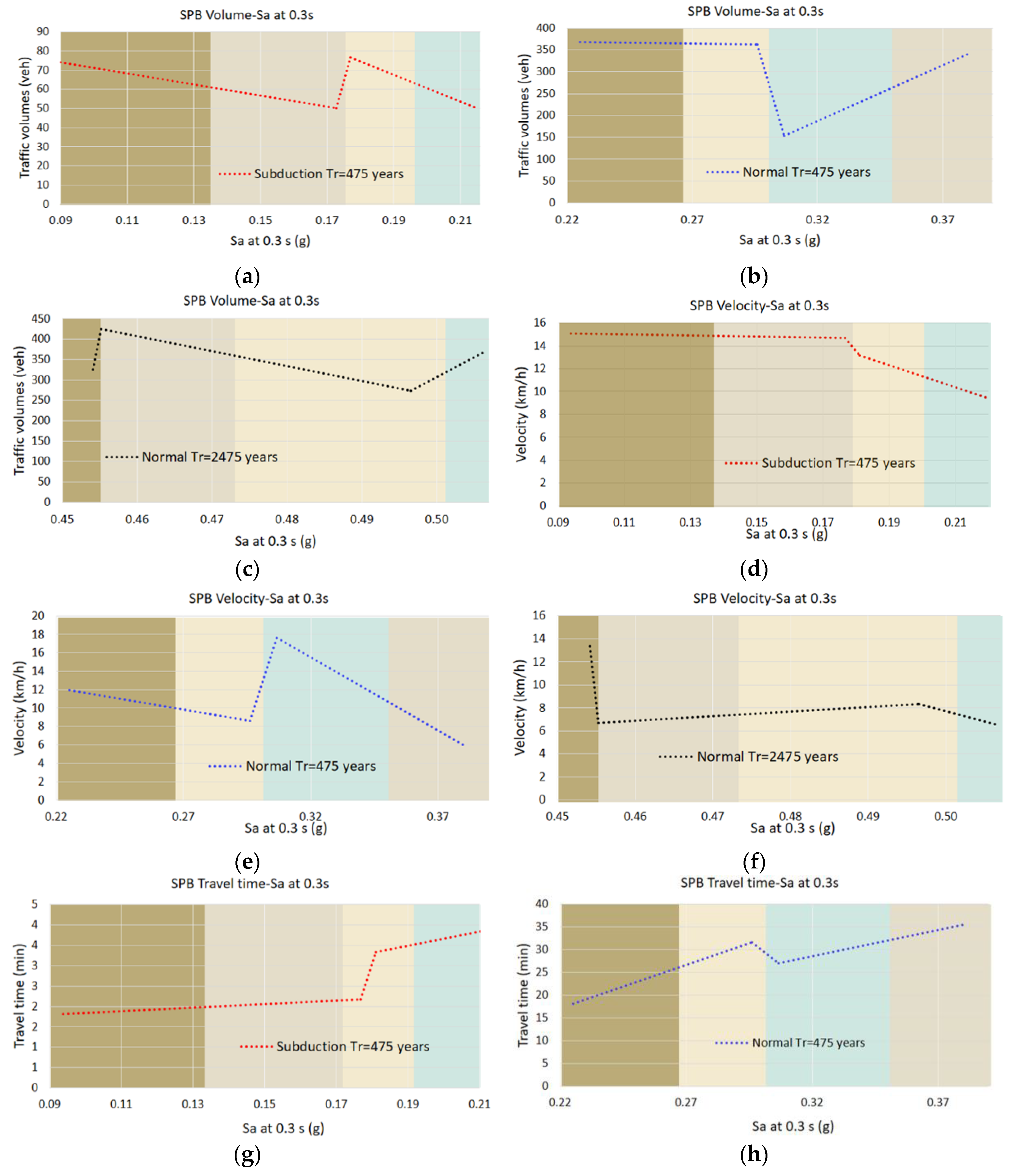
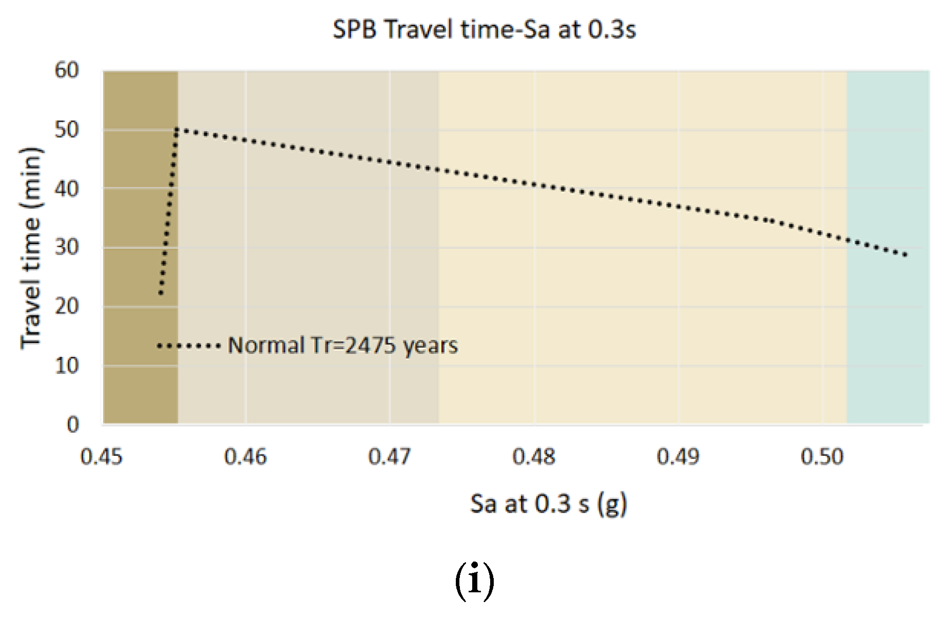
As buildings of 1–3 stories comprise over 90% of the structures in the study area, the seismic intensity is presented in terms of PGA and Sa at 0.3 s. Figure 24 depicts the seismic performance boundaries relating traffic parameter to PGA, for normal earthquakes, with Tr = 475 years and Tr = 2475 years, and for a subduction earthquake Tr = 475 years. The boundaries obtained for the case study, highlight the differences in the expected behavior of traffic within the study area when earthquakes with different frequency content occur, where traffic variables show particular patterns for each seismic scenario analyzed. In the case of subduction events, traffic is expected to distribute along more segments of the network showing lower values of traffic volumes. In the case of normal events, traffic volumes are expected to concentrate and hence be greater. Velocities reached in the subduction scenario show a pattern of decrement when ground motions increase. However, for normal events, velocities pattern shows peaks and valleys that may be related to the differences of the network topology in each geo-seismic zone. Travel time values are lower in the subduction scenario with a decrement pattern versus ground motions growth. Travel times follow non-linear behavior in normal scenarios and are expected to be greater than in the subduction case. The average capacity of segments, during a 10 min time interval, tends to decrease as seismic intensity increases, showing different patterns for subduction and normal events.
Figure 25 expresses SPB curves in terms of spectral accelerations Sa at 0.3 s. According to the curves obtained, after a subduction event, segments in Zone I and IIIa are expected to serve a greater number of vehicles that those in Zones II and IIIb, however, velocities reached are greater in Zones I and II, therefore segments in these zones experience shorter travel times than in other zones. In the case of a normal earthquake Tr = 475 years, greater traffic volumes are expected within roads in Zone I and II. Still Zones I and IIIa show greater velocity and travel time values. Some variations are observed with the magnitude increase since the normal earthquake scenario Tr = 2475 years forecast a decrement in velocities along Zones II, IIIa, and IIIb, and greater travel times in the same zones than in Zone I.
According to these results, segments located in Zones IIIa and IIIb were found to be more vulnerable to strong earthquake scenarios, than those in Zones I and II. In addition, the network studied was found to be vulnerable mainly to normal fault earthquakes, the impacts of which were more extensive, affecting a greater number of roads, than those of subduction events.
Projects to mitigate seismic vulnerability and increase the resilience of the network and post-earthquake urban mobility in the study area could include sustainable strategies or actions to improve the capacity of the network (e.g., public transport dedicated lanes, high-capacity buses) as well as improving the seismic response of structures (e.g., retrofitting campaigns).

4. Conclusions

Transport networks located in densely populated urban areas are subject to dynamic behavior and interdependencies that have rarely been considered in seismic vulnerability approaches. A multidisciplinary methodology was presented in this work, where the performance of transport networks after major earthquakes is expressed in terms of both traffic behavior variables and seismological parameters.
Using an optimization data analysis model, a performance measure, the TSP index was developed. This measure indicates the expected operational performance and seismic vulnerability of the urban transport network under specific seismic conditions.
As part of the performance model, a set of seismic boundary curves, expressing the relations between seismic and traffic behavior parameters, was developed. These curves highlight the most efficient elements of the network; the road segments best suited to face major earthquakes. Vulnerable elements in the network are also identified and evaluated by a TSP index value.
The methodology was applied to the road network located in an area in the south of Mexico City. It was observed that when major earthquakes occur here, the functionality and continuity of the network depends on the interaction of soil conditions, the characteristics of the built environment, and the capacity of the roads. In the case study, the road network was shown to be more vulnerable in areas of soft soil and in transition zones, where impacts on traffic conditions were more pronounced since damage and road closures were highly probable. Additionally, road closure procedures create more adverse traffic behavior patterns in zones where roads are low capacity, intersections are controlled by traffic lights, and there are no overpasses or tunnels. Then, a combined effect of the structural vulnerability of the built environment, and the network vulnerability associated with its topology may increase the vulnerability of the transport network.
The performance model also allowed the influence of the frequency content and magnitude of each earthquake on the network to be determined, through the TSP index. In the case study, normal fault events were seen to cause wider damage in the study area, disturbing traffic in soft soil zones mainly.
The methodology and performance model presented offer a procedure and a quantitative tool to evaluate the vulnerability and operational performance of urban transport networks. The identification of vulnerable parts in urban networks, and the potential effects of geo hazards, are vital in planning sustainable and resilient urban areas. Further research could address more accurate modeling procedures, to determine a detailed spatial distribution of ground motions in an area, which could reduce uncertainties in damage scenario modeling. By extending the modeling to include metro networks, railway systems, and trips using non-motorized transport modes, a comparison of seismic efficiency among transport modes would also be possible.

Author Contributions

Conceptualization, A.R.-d.l.S.; methodology, A.R.-d.l.S. and R.S.; formal analysis, A.R.-d.l.S.; investigation, A.R.-d.l.S.; data curation, A.R.-d.l.S.; writing—original draft preparation, A.R.-d.l.S.; writing—review and editing, R.S.; supervision, R.S. All authors have read and agreed to the published version of the manuscript.

Funding

This research received no external funding.

Acknowledgments

The authors would like to thank PTV Group for their support and availability in providing the traffic modeling tool. The authors would also like to thank Professor Juan M Mayoral, for the feedback from the revision of seismic aspects of this research, needed to establish the expected damage, prior to traffic and optimization analyses.

Conflicts of Interest

The authors declare no conflict of interest.

References

  1. Amirsardari, A.; Sofi, M.; Lumantarna, E.; Imran, I.; Duffield, C. Impact of Earthquakes on the Transportation Infrastructure of Indonesia: A Preliminary Study. Civ. Eng. Dimens. 2019, 21, 19–28. [Google Scholar] [CrossRef]
  2. Sarkis, A.I.; Palermo, A.; Kammouh, O.; Cimellaro, G.P. Seismic resilience of road bridges: Lessons learned from the 14 November 2016 Kaikōura Earthquake. In Proceedings of the 9th International Conference on Bridge Maintenance, Safety, Melbourne, Australia, 9–13 July 2018; p. 588. [Google Scholar]
  3. Düzgün, Ş.; Yücemen, M.S.; Kalaycioglu, H.S.; Celik, K.; Kemeç, S.; Ertugay, K.; Deniz, A. An integrated earthquake vulnerability assessment framework for urban areas. Nat. Hazards 2011, 59, 917–947. [Google Scholar] [CrossRef]
  4. Cubrinovski, M.; Hughes, M.; Bradley, B.A.; Noonan, J.; Hopkins, R.; McNeill, S.; English, G. Performance of Horizontal Infrastructure in Christchurch City through the 2010–2011 Canterbury Earthquake Sequence; University of Canterbury: Christchurch, New Zealand, 2014. [Google Scholar]
  5. Durante, M.G.; Di Sarno, L.; Zimmaro, P.; Stewart, J.P. Damage to Roadway Infrastructure from 2016 Central Italy Earthquake Sequence. Earthq. Spectra 2018, 34, 1721–1737. [Google Scholar] [CrossRef]
  6. Romeo, S.; Di Matteo, L.; Melelli, L.; Cencetti, C.; Dragoni, W.; Fredduzzi, A. Seismic-induced rockfalls and landslide dam following the October 30, 2016 earthquake in Central Italy. Landslides 2017, 14, 1457–1465. [Google Scholar] [CrossRef]
  7. Martino, S.; Bozzano, F.; Caporossi, P.; D’Angiò, D.; Della Seta, M.; Esposito, C.; Marmoni, G.M. Impact of landslides on transportation routes during the 2016–2017 Central Italy seismic sequence. Landslides 2019, 16, 1221–1241. [Google Scholar] [CrossRef]
  8. Bhattacharya, S.; Hyodo, M.; Nikitas, G.; Ismael, B.; Suzuki, H.; Lombardi, D.; Egami, S.; Watanabe, G.; Goda, K. Geotechnical and infrastructural damage due to the 2016 Kumamoto earthquake sequence. Soil Dyn. Earthq. Eng. 2018, 104, 390–394. [Google Scholar] [CrossRef]
  9. Kazama, M.; Noda, T. Damage statistics (Summary of the 2011 off the Pacific Coast of Tohoku Earthquake damage). Soils Found. 2012, 52, 780–792. [Google Scholar] [CrossRef] [Green Version]
  10. Nakanishi, H.; Black, J.; Matsuo, K. Disaster resilience in transportation: Japan earthquake and tsunami 2011. Int. J. Disaster Resil. Built Environ. 2014, 5, 341–361. [Google Scholar] [CrossRef]
  11. Kawashima, K. Damage of bridges due to the 2011 great east japan earthquake. J. Jpn. Assoc. Earthq. Eng. 2012, 12, 4. [Google Scholar] [CrossRef] [Green Version]
  12. Yasuda, S.; Towhata, I.; Ishii, I.; Sato, S.; Uchimura, T. Liquefaction-induced damage to structures during the 2011 great east japan earthquake. J. JSCE 2013, 1, 181–193. [Google Scholar] [CrossRef] [Green Version]
  13. Choi, E.; Desroches, R.; Nielson, B.G. Seismic fragility of typical bridges in moderate seismic zones. Eng. Struct. 2004, 26, 187–199. [Google Scholar] [CrossRef]
  14. Nielson, B.G.; Desroches, R. Seismic fragility methodology for highway bridges using a component level approach. Earthq. Eng. Struct. Dyn. 2007, 36, 823–839. [Google Scholar] [CrossRef]
  15. Misra, S.; Padgett, J.E. Seismic Fragility of Railway Bridge Classes: Methods, Models, and Comparison with the State of the Art. J. Bridg. Eng. 2019, 24, 04019116. [Google Scholar] [CrossRef]
  16. NIBS. Users’s manual and technical manuals. In Report Prepared for the Federal Emergency Management Agency; National Institute of Building Sciences (NIBS): Washington, DC, USA, 2004. [Google Scholar]
  17. Salmon, M.; Wang, J.; Jones, D.; Wu, C. Fragility Formulations for the BART System. In Advancing Mitigation Technologies and Disaster Response for Lifeline Systems; American Society of Civil Engineers (ASCE): Reston, VA, USA, 2003; pp. 183–192. [Google Scholar]
  18. Mayoral, J.M.; Argyroudis, S.; Castañon, E.; Argyroudis, S. Vulnerability of floating tunnel shafts for increasing earthquake loading. Soil Dyn. Earthq. Eng. 2016, 80, 1–10. [Google Scholar] [CrossRef]
  19. Maruyama, Y.; Yamazaki, F.; Mizuno, K.; Yogai, H.; Tsuchiya, Y. Development of fragility curves for highway embankment based on damage data from recent earthquakes in Japan. In Proceedings of the 14th World Conference on Earthquake Engineering, Beijing, China, 12–17 October 2008. [Google Scholar]
  20. Maruyama, Y.; Yamazaki, F.; Mizuno, K.; Tsuchiya, Y.; Yogai, H. Fragility curves for expressway embankments based on damage datasets after recent earthquakes in Japan. Soil Dyn. Earthq. Eng. 2010, 30, 1158–1167. [Google Scholar] [CrossRef]
  21. Argyroudis, S.; Kaynia, A.M. Analytical seismic fragility functions for highway and railway embankments and cuts. Earthq. Eng. Struct. Dyn. 2015, 44, 1863–1879. [Google Scholar] [CrossRef]
  22. Werner, S.D.; Taylor, C.E.; Cho, S.; Lavoie, J.P.; Huyck, C.K.; Eitzel, C.; Eguchi, R.T. Redars 2 Methodology and Software for Seismic Risk Analysis of Highway Systems; University of Buffalo: Buffalo, NY, USA, 2006. [Google Scholar]
  23. Pitilakis, K.; Crowley, H.; Kaynia, A.M. SYNER-G: Typology definition and fragility functions for physical elements at seismic risk. Geotech. Geol. Earthq. Eng. 2014, 27, 1–28. [Google Scholar]
  24. Anelli, A.; Mori, F.; Vona, M. Fragility Curves of the Urban Road Network Based on the Debris Distributions of Interfering Buildings. Appl. Sci. 2020, 10, 1289. [Google Scholar] [CrossRef] [Green Version]
  25. Ko, Y.Y.; Yang, H.H.; Chen, C.H. Seismic Fragility Analysis for Sheet Pile Wharves—Case Study of the Hualien harbor in Taiwan; Missouri University of Science and Technology: Rolla, MO, USA, 2010. [Google Scholar]
  26. Na, U.J.; Chaudhuri, S.R.; Shinozuka, M. Probabilistic assessment for seismic performance of port structures. Soil Dyn. Earthq. Eng. 2008, 28, 147–158. [Google Scholar] [CrossRef]
  27. Kakderi, K.; Pitilakis, K. Seismic Analysis and Fragility Curves of Gravity Waterfront Structures; Missouri University of Science and Technology: Rolla, MO, USA, 2010. [Google Scholar]
  28. Fäh, D.; Kind, F.; Lang, K.; Giardini, D. Earthquake scenarios for the city of Basel. Soil Dyn. Earthq. Eng. 2001, 21, 405–413. [Google Scholar] [CrossRef]
  29. Veneziano, D.; Sussman, J.M.; Gupta, U.; Kunnumkal, S.M. Earthquake loss under limited transportation capacity: Assessment, sensitivity and remediation. In Proceedings of the Seventh US National Conference on Earthquake Engineering, Boston, MA, USA, 21–25 July 2002. [Google Scholar]
  30. Singhal, A.; Kiremidjian, A.S. Method for Probabilistic Evaluation of Seismic Structural Damage. J. Struct. Eng. 1996, 122, 1459–1467. [Google Scholar] [CrossRef]
  31. Rossetto, T.; Elnashai, A. A new analytical procedure for the derivation of displacement-based vulnerability curves for populations of RC structures. Eng. Struct. 2005, 27, 397–409. [Google Scholar] [CrossRef]
  32. Lee, Y.J.; Song, J.; Gardoni, P.; Lim, H.-W. Post-hazard flow capacity of bridge transportation network considering structural deterioration of bridges. Struct. Infrastruct. Eng. 2011, 7, 509–521. [Google Scholar] [CrossRef]
  33. Nagurney, A.; Qiang, Q. A network efficiency measure for congested networks. EPL Europhys. Lett. 2007, 79, 38005. [Google Scholar] [CrossRef] [Green Version]
  34. Bocchini, P.; Frangopol, D.M. Connectivity-Based Optimal Scheduling for Maintenance of Bridge Networks. J. Eng. Mech. 2013, 139, 760–769. [Google Scholar] [CrossRef]
  35. Kurtz, N.; Song, J.; Gardoni, P. Seismic Reliability Analysis of Deteriorating Representative U.S. West Coast Bridge Transportation Networks. J. Struct. Eng. 2016, 142, C4015010. [Google Scholar] [CrossRef]
  36. Guikema, S.D.; Gardoni, P. Reliability Estimation for Networks of Reinforced Concrete Bridges. J. Infrastruct. Syst. 2009, 15, 61–69. [Google Scholar] [CrossRef]
  37. Chen, A.; Yang, C.; Kongsomsaksakul, S.; Lee, M. Network-based Accessibility Measures for Vulnerability Analysis of Degradable Transportation Networks. Netw. Spat. Econ. 2007, 7, 241–256. [Google Scholar] [CrossRef]
  38. Gomez, C.; Baker, J.W. An optimization-based decision support framework for coupled pre- and post-earthquake infrastructure risk management. Struct. Saf. 2019, 77, 1–9. [Google Scholar] [CrossRef]
  39. Liao, T.-Y.; Hu, T.-Y.; Ko, Y.-N. A resilience optimization model for transportation networks under disasters. Nat. Hazards 2018, 93, 469–489. [Google Scholar] [CrossRef]
  40. Fan, L.; Tangqing, L. Study on Optimization of Earthquake Transportation Emergency Management System. In Proceedings of the 7th International Conference on Innovation and Management, Tokyo, Japan, 7–10 February 2010; pp. 1851–1863. [Google Scholar]
  41. Üstün, A.K. Evaluating İstanbul’s disaster resilience capacity by data envelopment analysis. Nat. Hazards 2015, 80, 1603–1623. [Google Scholar] [CrossRef]
  42. El-Rashidy, R.A.; Grant-Muller, S.M. An assessment method for highway network vulnerability. J. Transp. Geogr. 2014, 34, 34–43. [Google Scholar] [CrossRef] [Green Version]
  43. Chang, L.; Elnashai, A.S., Jr. Post-earthquake modelling of transportation networks. Struct. Infrastruct. Eng. 2011, 8, 1–19. [Google Scholar] [CrossRef]
  44. Kilanitis, I.; Sextos, A. Integrated seismic risk and resilience assessment of roadway networks in earthquake prone areas. Bull. Earthq. Eng. 2018, 17, 181–210. [Google Scholar] [CrossRef] [Green Version]
  45. Feng, K.; Li, Q.; Ellingwood, B.R. Post-earthquake modelling of transportation networks using an agent-based model. Struct. Infrastruct. Eng. 2020, 1–15. [Google Scholar] [CrossRef] [Green Version]
  46. Taylor, M.A.P. Critical Transport Infrastructure in Urban Areas: Impacts of Traffic Incidents Assessed Using Accessibility-Based Network Vulnerability Analysis. Growth Chang. 2008, 39, 593–616. [Google Scholar] [CrossRef]
  47. Chen, A.; Kim, J.; Zhou, Z.; Chootinan, P. Alpha Reliable Network Design Problem. Transp. Res. Rec. J. Transp. Res. Board 2007, 2029, 49–57. [Google Scholar] [CrossRef]
  48. Argyroudis, S.A.; Mitoulis, S.A.; Hofer, L.; Zanini, M.A.; Tubaldi, E.; Frangopol, D.M. Resilience assessment framework for critical infrastructure in a multi-hazard environment: Case study on transport assets. Sci. Total. Environ. 2020, 714, 136854. [Google Scholar] [CrossRef]
  49. Argyroudis, S.A.; Mitoulis, S.A.; Winter, M.G.; Kaynia, A.M. Fragility of transport assets exposed to multiple hazards: State-of-the-art review toward infrastructural resilience. Reliab. Eng. Syst. Saf. 2019, 191, 106567. [Google Scholar] [CrossRef]
  50. Kermanshah, A.; Derrible, S. A geographical and multi-criteria vulnerability assessment of transportation networks against extreme earthquakes. Reliab. Eng. Syst. Saf. 2016, 153, 39–49. [Google Scholar] [CrossRef]
  51. Zhang, W.; Wang, N. Resilience-based risk mitigation for road networks. Struct. Saf. 2016, 62, 57–65. [Google Scholar] [CrossRef] [Green Version]
  52. Khademi, N.; Balaei, B.; Shahri, M.; Mirzaei, M.; Sarrafi, B.; Zahabiun, M.; Mohaymany, A.S. Transportation network vulnerability analysis for the case of a catastrophic earthquake. Int. J. Disaster Risk Reduct. 2015, 12, 234–254. [Google Scholar] [CrossRef]
  53. Dizhur, D.; Giaretton, M.; Ingham, J.M. Damage Observations Following the M w 7.8 2016 Kaikoura Earthquake. In Proceedings of the International Conference on Earthquake Engineering and Structural Dynamics, Reykjavík, Iceland, 12–14 June 2017; pp. 249–261. [Google Scholar]
  54. Marcianò, F.A.; Musolino, G.; Vitetta, A. Signal setting optimization on urban road transport networks: The case of emergency evacuation. Saf. Sci. 2015, 72, 209–220. [Google Scholar] [CrossRef]
  55. Musolino, G.; Vitetta, A. Short-term forecasting in road evacuation: Calibration of a travel time function. Urban Transport XVII 2011, 116, 615–626. [Google Scholar] [CrossRef] [Green Version]
  56. Marcianò, F.A.; Musolino, G.; Vitetta, A. Within-day traffic assignment and signal setting in road evacuation: A procedure with explicit path enumeration. WIT Trans. Built Environ. 2011, 117, 403–414. [Google Scholar] [CrossRef]
  57. Chilá, G.; Musolino, G.; Polimeni, A.; Rindone, C.; Russo, F.; Vitetta, A. Transport models and intelligent transportation system to support urban evacuation planning process. IET Intell. Transp. Syst. 2016, 10, 279–286. [Google Scholar]
  58. Charnes, A.; Cooper, W.W.; Rhodes, E. Measuring the efficiency of decision making units. Eur. J. Oper. Res. 1978, 2, 429–444. [Google Scholar] [CrossRef]
  59. Cornell, C.A. Engineering seismic risk analysis. Bull. Seismol. Soc. Am. 1968, 58, 1583–1606. [Google Scholar]
  60. Porter, K.R. A Beginner’s Guide to Fragility, Vulnerability, and Risk. Encycl. Earthq. Eng. 2015, 1–29. [Google Scholar] [CrossRef]
  61. Hirokawa, N.; Osaragi, T. Earthquake Disaster Simulation System: Integration of Models for Building Collapse, Road Blockage, and Fire Spread. J. Disaster Res. 2016, 11, 175–187. [Google Scholar] [CrossRef]
  62. Argyroudis, S.; Selva, J.; Gehl, P.; Pitilakis, K. Systemic Seismic Risk Assessment of Road Networks Considering Interactions with the Built Environment. Comput. Civ. Infrastruct. Eng. 2015, 30, 524–540. [Google Scholar] [CrossRef]
  63. Galvis, F.; Miranda, E.; Heresi, P.; Dávalos, H.; Silos, J.R. Preliminary statistics of collapsed buildings in Mexico City in the September 19, 2017 Puebla-Morelos Earthquake; Blume Earthquake Engineering Center; Department of Civil and Environmental Engineering Stanford University: Stanford, CA, USA, 2017. [Google Scholar]
  64. GEER. Geotechnical Engineering Reconnaissance of the 19 September 2017 Mw 7.1 Puebla-Mexico City Earthquake, Version 2.0; Geotechnical Extreme Events Reconnaissance Association: VA, USA, 2017; Available online: http://www.geerassociation.org/administrator/components/com_geer_reports/geerfiles/UNAM_GEER_Sept2017_v2_Final.pdf (accessed on 19 November 2020).
  65. Román-de la Sancha, A.; Mayoral, J.M.; Hutchinson, T.; Candia, G.; Montgomery, J.; Tepalcapa, S. Assessment of fragility models based on the Sept 19th, 2017 earthquake observed damage. Soil Dyn. Earthq. Eng. 2019, 125, 105707. [Google Scholar] [CrossRef]
  66. Lighthill, M.J.; Whitham, G.B. On kinematic waves II. A theory of traffic flow on long crowded roads. Proc. R. Soc. Lond. Ser. A Math. Phys. Sci. 1955, 229, 317–345. [Google Scholar] [CrossRef]
  67. Gazis, D.C.; Herman, R.; Potts, R.B. Car-Following Theory of Steady-State Traffic Flow. Oper. Res. 1959, 7, 499–505. [Google Scholar] [CrossRef]
  68. Pipes, L.A. An Operational Analysis of Traffic Dynamics. J. Appl. Phys. 1953, 24, 274–281. [Google Scholar] [CrossRef]
  69. Wang, Y.; Szeto, W.; Han, K.; Friesz, T.L. Dynamic traffic assignment: A review of the methodological advances for environmentally sustainable road transportation applications. Transp. Res. Part B: Methodol. 2018, 111, 370–394. [Google Scholar] [CrossRef]
  70. Pi, X.; Ma, W.; Qian, Z. (Sean) A general formulation for multi-modal dynamic traffic assignment considering multi-class vehicles, public transit and parking. Transp. Res. Part C Emerg. Technol. 2019, 104, 369–389. [Google Scholar] [CrossRef]
  71. Zhang, Y.; Atasoy, B.; Akkinepally, A.; Ben-Akiva, M. Dynamic Toll Pricing using Dynamic Traffic Assignment System with Online Calibration. Transp. Res. Rec. J. Transp. Res. Board 2019, 2673, 532–546. [Google Scholar] [CrossRef]
  72. Wardrop, J.G. Road paper. some theoretical aspects of road traffic research. Proc. Inst. Civ. Eng. 1952, 1, 325–362. [Google Scholar] [CrossRef]
  73. Ortúzar, J.D.; Willumsen, L.G. Modelling Transport; John Wiley & Sons: New York, NY, USA, 2011. [Google Scholar]
  74. Kamga, C.N.; Mouskos, K.C.; Paaswell, R.E. A methodology to estimate travel time using dynamic traffic assignment (DTA) under incident conditions. Transp. Res. Part C Emerg. Technol. 2011, 19, 1215–1224. [Google Scholar] [CrossRef]
  75. Peeta, S.; Ziliaskopoulos, A.K. Foundations of Dynamic Traffic Assignment: The Past, the Present and the Future. Netw. Spat. Econ. 2001, 1, 233–265. [Google Scholar] [CrossRef]
  76. Sisiopiku, V.P.; Li, X. Overview of dynamic traffic assignment options. In Proceedings of the 2006 Transportation Simulation Symposium, Huntsville, AL, USA, 2–6 April 2006. [Google Scholar]
  77. Mahut, M.; Florian, M.; Tremblay, N.; Campbell, M.; Patman, D.; McDaniel, Z.K. Calibration and Application of a Simulation-Based Dynamic Traffic Assignment Model. Transp. Res. Rec. J. Transp. Res. Board 2004, 1876, 101–111. [Google Scholar] [CrossRef]
  78. Instituto Nacional de Estadística y Geografía (INEGI). Encuesta Origen-Destino en hogares de la Zona Metropolitana del Valle de México; Instituto Nacional de Estadística Geografía e Informática: Mexico City, México, 2017. [Google Scholar]
  79. Mayoral, J.M.; Asimaki, D.; Tepalcapa, S.; Wood, C.; Román-de la Sancha, A.; Hutchinson, T.; Franke, K.; Montalva, G. Site effects in Mexico City basin: Past and present. Soil Dyn. Earthq. Eng. 2019, 121, 369–382. [Google Scholar] [CrossRef]
  80. Government of Mexico City. RCDF 2004 NTCDS-RCDF Normas Técnicas Complementarias para el Diseño por Sismo; Government of Mexico City: Mexico City, Mexico, 2004. (In Spanish)
  81. Mayoral, J.M.; Romo, M.P. Seismic response of bridges with massive foundations. Soil Dyn. Earthq. Eng. 2015, 71, 88–99. [Google Scholar] [CrossRef]
  82. Mayoral, J.; Tepalcapa, S.; Román-de la Sancha, A.; El Mohtar, C.; Rivas, R. Ground subsidence and its implication on building seismic performance. Soil Dyn. Earthq. Eng. 2019, 126, 105766. [Google Scholar] [CrossRef]
  83. Seed, H.B.; Romo, M.P.; Sun, J.I.; Jaime, A.; Lysmer, J. The Mexico Earthquake of September 19, 1985—Relationships between Soil Conditions and Earthquake Ground Motions. Earthq. Spectra 1988, 4, 687–729. [Google Scholar] [CrossRef]
  84. Romo, M.P. Clay behavior, ground response and soil-structure interaction studies in Mexico City. In Proceedings of the 3rd International Conference on Recent Advances in Geotechnical Earthquake Engineering and Soil Dynamics, St. Louis, MI, USA, 6–12 April 1995. [Google Scholar]
  85. Servicio Sismológico Nacional, SSN 2020. Available online: http://www2.ssn.unam.mx:8080/mapas-de-intensidades/ (accessed on 1 September 2020).
  86. Government of Mexico City. RCDF 2017 NTCDS-RCDF Normas Técnicas Complementarias para el Diseño por Sismo; Government of Mexico City: Mexico City, Mexico, 2017. (In Spanish)
  87. Bárcena, A.; Romo, M.P. RADSH: Programa de Computadora Para Analizar Depósitos de Suelo Estratificados Horizontalmente Sujetos a Excitaciones Dinámicas Aleatorias; Informe del Instituto de Ingeniería, Universidad Nacional Autónoma de México: Mexico City, Mexico, 1994. (In Spanish) [Google Scholar]
  88. Osorio, L.; Mayoral, J.M. Seismic microzonation for the northeast Texcoco lake area, Mexico. Soil Dyn. Earthq. Eng. 2013, 48, 252–266. [Google Scholar] [CrossRef]
  89. Itasca Consulting Group. FLAC, Fast Lagragian Analysis of Continua, User׳s Guide; Itasca Consulting Group: Minnesota, MN, USA, 2005. [Google Scholar]
  90. Lilhanand, K.; Tseng, W.S. Development and application of realistic earthquake time histories compatible with multiple-damping design spectra. In Proceedings of the 9th World Conference on Earthquake Engineering, Tokyo-Kyoto, Japan, 2–6 August 1988; pp. 819–824. [Google Scholar]
  91. Abrahamson, N.A. Non-Stationary Spectral Matching Program RSPMATCH; Pacific Gas & Electric Company: San Francisco, CA, USA, 1998. [Google Scholar]
  92. Mayoral, J.M.; De La Rosa, D.; Tepalcapa, S. Topographic effects during the September 19, 2017 Mexico city earthquake. Soil Dyn. Earthq. Eng. 2019, 125, 105732. [Google Scholar] [CrossRef]
  93. Schnabel, P.B. SHAKE: A Computer Program for Earthquake Response Analysis of Horizontally Layered Sites; EERC Report 72-12; University of California: Berkeley, CA, USA, 1972. [Google Scholar]
  94. Chong, S.-H. Soil Dynamic Constitutive Model for Characterizing the Nonlinear-Hysteretic Response. Appl. Sci. 2017, 7, 1110. [Google Scholar] [CrossRef] [Green Version]
  95. Liu, X.; Cheng, X.; Scarpas, A.; Blaauwendraad, J. Numerical modelling of nonlinear response of soil. Part 1: Constitutive model. Int. J. Solids Struct. 2005, 42, 1849–1881. [Google Scholar] [CrossRef]
  96. Groholski, D.R.; Hashash, Y.M.; Kim, B.; Musgrove, M.; Harmon, J.A.; Stewart, J.P. Simplified Model for Small-Strain Nonlinearity and Strength in 1D Seismic Site Response Analysis. J. Geotech. Geoenviron. Eng. 2016, 142, 04016042. [Google Scholar] [CrossRef]
  97. Mayoral, J.M.; Romo, M.P.; Osorio, L. Seismic parameters characterization at Texcoco lake, Mexico. Soil Dyn. Earthq. Eng. 2008, 28, 507–521. [Google Scholar] [CrossRef]
  98. Mayoral, J.M.; Castañon, E.; Alcantara, L.; Tepalcapa, S. Seismic response characterization of high plasticity clays. Soil Dyn. Earthq. Eng. 2016, 84, 174–189. [Google Scholar] [CrossRef]
  99. Mayoral, J.M.; Ramírez, J. Site response effects on an urban overpass. Soil Dyn. Earthq. Eng. 2011, 31, 849–855. [Google Scholar] [CrossRef]
  100. González, C.M.; Romo, M.P. Estimación de Propiedades Dinámicas de Arcillas. Ing. Sísmica 2011, 84, 1–23. (In Spanish) [Google Scholar] [CrossRef]
  101. Vucetic, M.; Dobry, R. Effect of Soil Plasticity on Cyclic Response. J. Geotech. Eng. 1991, 117, 89–107. [Google Scholar] [CrossRef]
  102. Seed, H.B.; Idriss, I.M. Soil Moduli and Damping Factors for Dynamics Response Analysis; Calif. Report No. EERC 70–10; University of California: Berkeley, CA, USA, 1970. [Google Scholar]
  103. Mayoral, J.M.; Badillo, A.; Alcaraz, M. Vulnerability and recovery time evaluation of an enhanced urban overpass foundation. Soil Dyn. Earthq. Eng. 2017, 100, 1–15. [Google Scholar] [CrossRef]
  104. Ruiz-García, J.; Negrete, M. Drift-based fragility assessment of confined masonry walls in seismic zones. Eng. Struct. 2009, 31, 170–181. [Google Scholar] [CrossRef]
  105. Villar-Vega, M.; Silva, V.; Crowley, H.; Yepes, C.; Tarque, N.; Acevedo, A.B.; Hube, M.A.; Gustavo, C.D.; María, H.S. Development of a Fragility Model for the Residential Building Stock in South America. Earthq. Spectra 2017, 33, 581–604. [Google Scholar] [CrossRef]
  106. Jara, J.M.; Olmos, B.A.; Martínez, G. Dynamic properties and seismic vulnerability of typical RC bridges located in México. Procedia Eng. 2017, 199, 2973–2978. [Google Scholar] [CrossRef]
  107. Díaz, S.A.; Pujades, L.G.; Barbat, A.H.; Hidalgo-Leiva, D.; Vargas-Alzate, Y.F. Capacity, damage and fragility models for steel buildings: A probabilistic approach. Bull. Earthq. Eng. 2017, 16, 1209–1243. [Google Scholar] [CrossRef] [Green Version]
  108. NIBS. Users’s manual and technical manuals. In Report Prepared for the Federal Emergency Management Agency; National Institute of Building Sciences: Washington, DC, USA, 2012. [Google Scholar]
  109. PTV. 2006. Available online: http://www.english.ptv.de/cgi-bin/traffic/traf-vision.pl (accessed on 5 December 2018).
  110. Mahut, M. A multi-lane link model of traffic dynamics based on the “space-time” queue. In Proceedings of the ITSC 2001, 2001 IEEE Intelligent Transportation Systems, Oakland, CA, USA, 25–29 August 2002; pp. 122–126. [Google Scholar]
  111. Florian, M.; Mahut, M.; Tremblay, N. Application of a simulation-based dynamic traffic assignment model. Eur. J. Oper. Res. 2008, 189, 1381–1392. [Google Scholar] [CrossRef]
  112. MaxDEA. Basic [Computer Program]; Version 5.0; Beijing Realworld Research & Consultation Company Ltd.: Beijing, China, 2014. [Google Scholar]
Figure 1. Methodology for seismic response and multivariable performance assessment of transport networks.
Sustainability 12 09726 g001
Figure 2. Location of buildings damaged during the 2017 Mexico City earthquake. Pink lines indicate roads closed due to the damage to buildings nearby.
Sustainability 12 09726 g002
Figure 3. Seismic performance boundaries (SPB) for urban transport networks.
Sustainability 12 09726 g003
Figure 4. Study area location and seismic zones according to the Mexico City building code.
Sustainability 12 09726 g004
Figure 5. Buildings and transport infrastructure in the study area.
Sustainability 12 09726 g005
Figure 6. Soil profile characteristics, (a) Seismic Zone II, (b) Seismic Zone IIIa; and (c) Seismic Zone IIIb.
Sustainability 12 09726 g006aSustainability 12 09726 g006b
Figure 7. Trip distribution during the day. Peak hours are shown in red.
Sustainability 12 09726 g007
Figure 8. (a) Shake map corresponding to the subduction event on June 23rd, 2020, (b) zoom of the study area for the same event.
Sustainability 12 09726 g008
Figure 9. (a) Shake map corresponding to the normal event on September 19th, 2017, (b) zoom of the study area for the same event.
Sustainability 12 09726 g009
Figure 10. Uniform hazard spectra for (a) subduction and (b) normal events.
Sustainability 12 09726 g010
Figure 11. Column of soil considered in the three-dimensional finite differences model.
Sustainability 12 09726 g011
Figure 12. Strong seed ground motions used in the time-domain spectral matching, (a) subduction (b) normal event.
Sustainability 12 09726 g012
Figure 13. (a) Normalized shear modulus and (b) damping curves [100,101,102].
Sustainability 12 09726 g013
Figure 14. Response spectra for Zone II (a) subduction and (b) normal events.
Sustainability 12 09726 g014
Figure 15. Response spectra for Zone IIIa (a) subduction and (b) normal events.
Sustainability 12 09726 g015
Figure 16. Response spectra for Zone IIIb (a) subduction and (b) normal events.
Sustainability 12 09726 g016
Figure 17. Approximation of (a) PGA and (b) PGD spatial distribution within the study area for subduction earthquakes.
Sustainability 12 09726 g017aSustainability 12 09726 g017b
Figure 18. Approximation of (a) PGA and (b) PGD spatial distribution within the study area for normal earthquakes.
Sustainability 12 09726 g018
Figure 19. Distribution of average probability of all damage states of buildings for (a) subduction and (b) normal events, Tr = 125, 250, 475, and 2475 years.
Sustainability 12 09726 g019
Figure 20. Red lines indicate the road segments which will be closed as safety procedures in (a) subduction and (b) normal earthquakes.
Sustainability 12 09726 g020
Figure 21. Measured vs. simulated (a) travel time, (b) average velocity, and (c) traffic volume for segments of the network.
Sustainability 12 09726 g021aSustainability 12 09726 g021b
Figure 22. Travel times in morning peak hour (a) typical conditions, (b) subduction earthquake Tr = 475 years, (c) normal earthquake Tr = 475 years. Black circles indicate areas with an increase in the travel time with respect to typical traffic conditions.
Sustainability 12 09726 g022aSustainability 12 09726 g022b
Figure 23. Seismic performance maps obtained for subduction earthquakes, Tr = 475 years, and normal fault earthquakes scenarios, Tr = 475 and 2475 years.
Sustainability 12 09726 g023
Figure 24. Seismic performance boundaries relating PGA and (a) traffic volumes, (b) velocity, (c) travel time and (d) capacity for normal and subduction scenarios.
Sustainability 12 09726 g024
Figure 25. SPB curves relating spectral accelerations and volumes for (a) subduction event (b) normal event T = 475 years and (c) normal event T = 2475 years; velocity (d) subduction event (e) normal event T = 475 years and (f) normal event T = 2475 years, and travel time (g) subduction event (h) normal event T = 475 years and (i) normal event T = 2475 years. Colors in the rectangles correspond with the geo-seismic zoning in Figure 6.
Sustainability 12 09726 g025aSustainability 12 09726 g025b
Table 1. Variables and parameters used for the performance model of an urban road network.
ModelInputOutput
Output orientedLink length (l) (m)
Number of lanes (Ln)
Free flow velocity (v0) (km/h)
Peak ground acceleration (PGA) (g) 1
Spectral acceleration at 0.1 s (Sa0.1) (g) 1
Spectral acceleration at 0.3 s (Sa0.3) (g) 1
Current velocity (v) (km/h)
Traffic volume (V) (veh/time interval)
Queue length (q) (1/m) 1
Travel time (Tt) (1/s) 1
Note: 1 The corresponding inverse value is used.
Table 2. Building and transportation infrastructure typologies.
ClassificationAbbreviationDescription
Buildings1 story masonry building1 MBConfined masonry buildings
2 story masonry building2 MBConfined masonry buildings
3 story masonry building3 MBConfined masonry buildings
4 story concrete building4 CBReinforced concrete infilled frame ductile buildings
5 story concrete building5 CBReinforced infilled frame ductile concrete buildings
6 story concrete building6 CBReinforced infilled frame ductile concrete buildings
7 story concrete building7 CBReinforced infilled frame ductile concrete buildings
8 story concrete building8 CBReinforced concrete wall system buildings
9 story concrete building9 CBReinforced concrete wall system buildings
10 story concrete building10 CBReinforced concrete wall system buildings
Transport infrastructureSingle span bridgesSP BAll single-span bridges
Concrete, multi-column bent, simple support (seismic design) bridgeCSS BConcrete slab, multi-beam or girder, box beam bridge.
Continuous concrete, single column, box girder (seismic design) bridgeCCSC BConcrete box beam bridge
Continuous concrete (seismic design) bridgeCC1 BConcrete slab, multi-beam or girder, box beam bridge
Steel, multi-column bent, simple support (seismic design) bridgeSSS BSteel slab, multi-beam or girder, box beam bridge
PS concrete, multi-column bent, simple support (seismic design) bridgePS SS BPS concrete slab, multi-beam or girder, box beam bridge
PS concrete, single column, box girder (seismic design) bridgePS BPS concrete box beam bridge
Continuous concrete, (seismic design) bridgeCC2 BConcrete slab, multi-beam or girder, box beam, frame bridge
Bored and drilled tunnelBD TBored and drilled tunnel
Cut and cover tunnelCC TCut and cover tunnel
Metro stationMS2 and 3 stories reinforced concrete walls buildings. Ductile behavior.
Metro and light railway tracksMTEmbankment
Main roadsMRUp to 2 lanes
Urban roadsURMore than 2 lanes
Table 3. Events considered to define the seed ground motions for time-domain analysis.
EventStationMagnitudeEpicentral Distance (km)Focal Depth (km)PGA (g)
19/09/2017C.U.Mw = 7.1114570.059
19/09/1985C.U.Mw = 8.139850.033
Table 4. Peak ground acceleration (PGA) (g) values obtained for each zone and for every return period.
Return Period, Tr (Years)Zone IZone IIZone IIIaZone IIIb
Subduction earthquake1250.04380.07720.10000.1260
2500.05300.09420.12100.1570
4750.06250.11270.14100.1830
24750.08920.16370.19100.2540
Normal fault earthquake1250.07640.10990.08400.0900
2500.10550.12990.11000.1180
4750.14060.16650.13900.1510
24750.25990.25580.21900.2430
Table 5. Spectral acceleration, Sa at 0.1 s (g) values obtained for each zone and for every return period.
Return Period, Tr (Years)Zone IZone IIZone IIIaZone IIIb
Subduction earthquake1250.04580.08660.10730.1301
2500.05600.10510.12740.1600
4750.06620.12300.14800.1861
24750.09680.17160.19640.2559
Normal fault earthquake1250.10600.15800.12240.1193
2500.14270.19410.15050.1430
4750.18850.23410.18050.1760
24750.34650.31100.26620.2537
Table 6. Spectral acceleration, Sa at 0.3 s (g) values obtained for each zone and for every return period.
Return Period, Tr (Years)Zone IZone IIZone IIIaZone IIIb
Subduction earthquake 1250.06520.12380.12440.1511
2500.07740.15260.15210.1868
4750.09370.17720.18090.2198
24750.13040.24530.22210.2874
Normal fault earthquake1250.12640.23430.14850.1770
2500.17220.30250.20620.2408
4750.22520.38150.29600.3067
24750.41280.57790.45800.4800
Table 7. Permanent ground displacement (PGD) (m) values obtained for each zone and for every return period.
Return Period, Tr (Years)Zone IZone IIZone IIIaZone IIIb
Subduction earthquake1250.0000.0360.0350.034
2500.0000.0340.0340.031
4750.0000.0500.0480.048
24750.0000.0120.0130.019
Normal fault earthquake1250.0000.0010.0010.000
2500.0000.0050.0050.004
4750.0000.0150.0160.015
24750.0000.0380.0380.038
Table 8. Fragility curves selected for the case study.
InfrastructureReferenceIntensity Measure
Reinforced concrete buildings (4, 5, 6, 7, 8, 9, 10 stories)[105]PGA and Sa
Confined masonry buildings (1, 2, 3 stories)[105]PGA and Sa
Bridges[108]PGA
Tunnels[23]PGD
Metro stations[105]PGA and Sa
Railway systems[23]PGD
Motorways[23]PGD
Urban roads[23]PGD
Table 9. Correlation coefficient, R2, for measured and modeled average travel time, velocity, and traffic volume.
Average Travel TimeAverage VelocityTraffic Volume
R2 First model (5 control segments)0.34330.00700.7153
R2 Final model (10 control segments)0.83680.65290.9196
Table 10. Average changes to traffic behavior within segments for three scenarios.
ScenarioAverage Travel Velocity (km/h)Average Travel Time (s)Maximum Queue Length (m)
Pre-earthquake conditions49.4215.4056.23
Subduction earthquakeTr = 475 years22.1033.6261.24
Normal earthquakeTr = 475 years44.19827.89156.03
Tr = 2475 years41.071304.01145.93
Table 11. Correlation coefficient, R2, obtained relating seismic and traffic variables.
Normal Fault, Tr = 475 YearsNormal Fault, Tr = 2475 YearsSubduction, Tr = 475 Years
PGASa0.1Sa0.3PGASa0.1Sa0.3PGASa0.1Sa0.3
Capacity0.4290.6810.6870.0080.0110.7850.4560.4260.402
v0.4130.6420.6990.0000.0020.7690.6920.6310.455
Tt0.5520.6330.8560.0350.0100.8820.3340.2770.109
q0.1130.0360.0150.0620.1220.0100.3150.2560.098
V0.4810.0360.4900.0070.2450.6800.7690.7160.565
Publisher’s Note: MDPI stays neutral with regard to jurisdictional claims in published maps and institutional affiliations.