1. Introduction
The geothermal energy sector has proven its ability to provide base load electricity and heat, but still requires further advancements to overcome the technical and site specific limitations. Enhanced geothermal systems (EGS) have been shown to theoretically access geothermal energy widely, and to produce electricity at lower costs and with fewer geographical constraints [
1]. A hydraulic stimulation is usually needed to ensure the creation of a connected path-flow in artificial fractures. This process has been successfully achieved in several field sites [
2]. A large volume of water injected at low pressure has been notably efficient at generating enhanced fracture permeabilities in the Newberry Volcano EGS demonstration site [
3]. However, the commercialisation of EGS has not yet been validated due to induced seismicity issues [
4], poor reservoir connectivity, and the absence of long-term regulatory policies in place [
5].
EGS single-well methods can provide an alternative solution to make stimulation unnecessary, by circulating a working fluid in a sealed well, or by connecting the wellbore to pre-existing fractures or in-situ geothermal fluids [
6,
7,
8,
9]. Closed wellbores such as borehole heat exchangers have been conventionally investigated for depths less than 1000 m [
10,
11]. To date, deep borehole/coaxial heat exchangers (DBHE/DCHE) have mainly been used for heating and cooling purposes [
12,
13]; they have also been proposed as a heat extraction method above magma bodies to exploit unattractive low productive geothermal zones (typically non-permeable) [
14]. The DBHE performances have been shown unaltered by the recovery cycles with identical flow rates in the Weggis plant, Switzerland [
13]. For this type of system, the working fluid (water, CO
2 or isobutene) only circulates in a closed well through an annular space [
6] or through different systems such as U-tubes or parallel DBHEs [
15,
16], without geothermal fluid production. Various technology-derived concepts, such as horizontal BHEs, can provide long-term heat power in the range 0.35–2.0 MW. For such systems, three different decreasing temperature slopes as functions of the horizontal section length have been studied [
8,
17]. A U-shaped well filled with CO
with a flow rate of 25 kg/s has been shown to provide more than 2.5 MW, with a thermosiphon [
18], without pumping.
Closed-wellbore models are generally coupled with a reservoir model to account for the heat exchange and fluid flow in the surrounding porous or fractured rocks [
6]. Fast simulations using a finite line source model have also been performed to investigate intermittent conditions in a DBHE [
19]. Closed wells have been investigated with several geothermal gradients from 25 to 50
C/km and between 2 to 6 km. When considering 50
C/km, the power production starts to be economically viable at depths more than 3 km. In addition, direct power generation systems have appeared more efficient with supercritical fluids than flashing power generation systems [
20]. The application of DBHEs worldwide reaches a maximum depth of 3 km when generating 0.15 to 2.5 MW of thermal power and 0.25 to 364 kW of electrical power [
6]. In deep reservoirs, the DBHE’s installed capacity has been shown to be highly sensitive to the reservoir’s porosity and the rock’s thermal conductivity [
21]. The well’s thermal conductivity is a function of the material used (e.g., one layered with steel or double layered with a vacuum), with values down to 10
W/m·K for the inner pipe in [
22]. The thermal insulation of the inner pipe, the mass flow rate and the geothermal heat flux are the most important parameters affecting the thermal performances.
Various numerical and analytical tools have been used to investigate DBHEs [
6]. The use of the constant fluid properties assumption generates errors in the calculation of the thermal and pressure losses in the DBHE [
23]. While the assumption of constant water properties can be acceptable in a low geothermal gradient context (1.8% difference in the thermal resistance in [
24] for 30
C/km), this is no longer valid in high geothermal gradients and for deeper DBHEs. Assuming constant water properties can underestimate the temperature of the water produced and heat flux for a DBHE of 6100 m [
25] and can overestimate the performances by 11% in a DBHE of 3500 m [
26]. Therefore, the use of pressure-temperature dependent thermophysical properties is important, especially the fluid specific heat, the viscosity and the thermal conductivity [
27]. The overall performance of a DBHE is limited by the surface heat exchange (in the wellbore) between the working fluid and the reservoir, which renders those systems more efficient for supplying heat rather than electricity, even in the case of very high geothermal gradients [
28]. To increase the thermal performances of DBHEs, different patented well designs could increase the heat transfer rate of DBHEs/DCHEs by enhancing the well thermal properties.
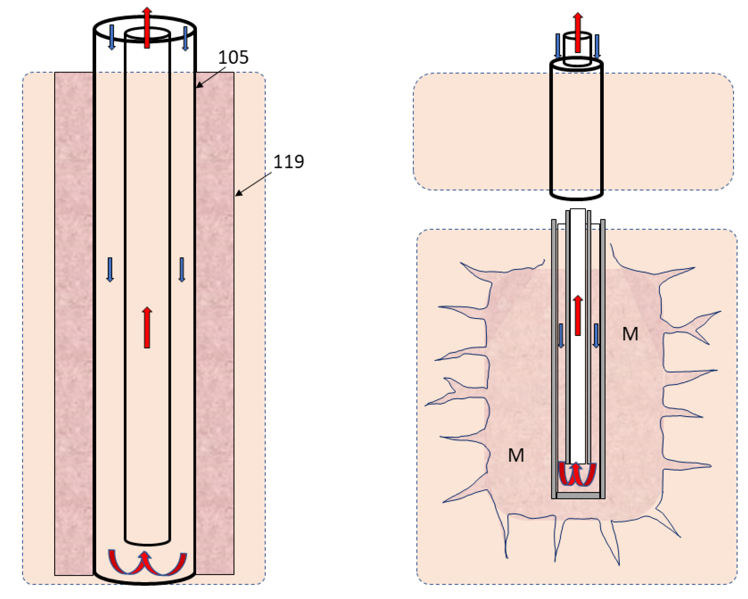
Figure 1 (Left) shows the implementation of graphite between the external casing and the rock around a single well, proposed by Hara [
29], using highly conductive fillers of graphite between the external casing (105) and the cement or surrounding rocks (119) of a DCHE.
As the cement thermal conductivity is a key parameter [
31], the injection of highly conductive materials such as graphite (500 to 140 W/m·K) into the well surroundings has been proposed by Buchi [
30] to create an enhanced conductive area with the injection of a high conductive material M in the near bottom hole (see
Figure 1 Right). Despite requiring injection processes in Buchi’s technology, these innovations would empower DBHEs under certain conditions, as numerically evaluated in [
32]. If the heat transfer rate is sufficient, both technologies described in
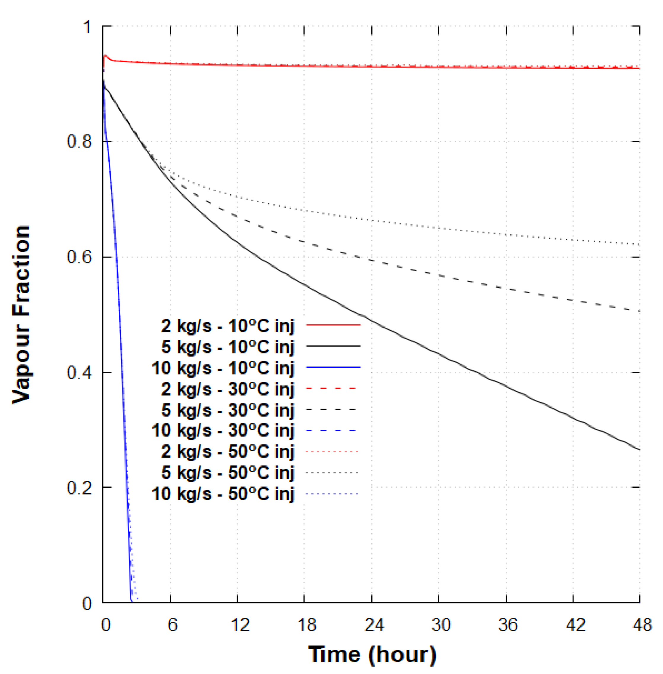
Figure 1 could produce a variable vapour fraction. The additional use of a downhole choke, or a boiler, could facilitate the phase change process by decreasing the pressure, as proposed in [
7].
After presenting and validating the DBHE numerical model, this study investigates the heat recovery of enhanced DBHE/DCHEs designs for different theoretical geothermal settings, using the T2Well integrated wellbore–reservoir simulator [
33], considering graphite in the well surroundings. At last, a numerical case study in the Newberry EGS system is presented.
2. Materials and Methods
This section introduces the experimental DBHE used to validate the numerical model, followed by the mathematical formulation of T2Well and the settings of the DBHE numerical model. The geometries considered for the investigation of the two theoretical DBHE patents with graphite in different geothermal environments are presented, and compared with a conventional DBHE, without graphite. The parameters used in a 2D numerical DBHE doublet model are described. These parameters are used to investigate the DBHE performances in an EGS case study.
2.1. Model Description
Figure 2 (Left) shows a DCHE-DBHE used in the HGP-A well in Hawaii [
34], in basaltic formations, with the downward injection of water through an external annulus. The grey filled material between the casing sections is the cement.
Figure 2 (Right) shows a view of the orthogonal mesh generated, highlighting the wellbore flow domain and the rock domain extended to the radial distance of 100 m. As the water flows down, it is heated before flowing back to the surface and requires pumping or is self-rising due to the thermosiphon effect via the internal tubing.
As the system is fully sealed, no contact between the geothermal fluids (or rocks) and the water takes place. In addition, the cement surrounding the well has been replaced by a highly thermally conductive material, graphite in the present study, to investigate the potential of both patents.
2.2. Mathematical Formulation
T2Well/EOS1 is a wellbore reservoir simulator with a 1D, two-phase momentum equation for the wellbore and the 3D multiphase Darcy law in the reservoir [
33]. T2Well solves the mass and energy balance equations numerically using a finite difference scheme. The momentum balance equation for the wellbore flow is solved numerically with a semi-explicit scheme [
35]. The code has been applied previously to model closed-loop U-shaped geothermal wells [
18], and other cases [
33]. It uses the IAPWS-IF97 formulation for water [
36]. The connections between the well and the formations have been closed to fluid flow so that only the conductive heat transfer between the wellbore and the surrounding formations is considered. Kinetic energy is considered in the wellbore where velocity can be high and is ignored in the reservoir at low fluid velocities. The conservation of mass for a two-phase system is written as [
33]:
The conservation of energy in the reservoir and wellbore are:
The liquid and gas velocities in the geothermal formations are calculated as:
where
k is the absolute permeability;
is the phase relative permeability;
are the sums of the respective phase pressure (gas) and the capillary pressure in the porous media. The parameters and their units are described in the Nomenclature.
A drift flux model (DFM) is used to model the interfacial interactions between the gas and the liquid, assuming that the gas velocity is related to the volumetric flux of the mixture. The DFM treats the drift velocity as an average, efficiently solving the complex two-phase flow in the wellbore [
35]. The drift velocity of gas
and the momentum equations of a two-phase flow in the wellbore are presented in
Appendix A. The Equation of State 1 (EOS1) module has been used with T2Well in this work [
37].
2.3. Model Validation
To apply T2Well in high-temperature settings with various vertical closed loop designs, the experimental data from the HGP-A well in Hawaii have been used to model a DBHE in a volcanic geothermal system. A temperature of 358
C was measured at a depth of 1962 m. After having sealed the well, the experiment was performed in a 7” casing by installing an insulated internal tubing up to the depth of 876.5 m, i.e., 3 m above the bottom of the test section. A water mass flow rate of 1.33 kg/s at 30
C was injected into the annular space for 7 days. A maximum thermal output powers of 373 kW, and 76 kW were measured after 7 days [
34]. The experiments aimed to validate a heat extraction method in low-production geothermal reservoirs, and super-hot rocks adjacent to solidified magma bodies [
14].
An axisymmetric mesh refined near the well to consider the casing and cement sections shown in
Figure 2 (Right) has been used with the numerical code T2Well/EOS1. The top of the reservoir was assumed to be 30
C and 1 bar; a temperature of 350
C was set as a constant at 1931 m, as described in [
14].
Table 1 shows the different casing and cement properties of the experimental settings considered in the numerical model. The T2Well-based simulation, experimental data and pressure–temperature simulations from [
34] were all based on the thermal parameters listed in
Table 1. The mesh contained 1310 cells, starting with a radial cell distance corresponding to the well geometry shown in
Figure 2 (Left), and increasing the lateral cell sizes following a logarithmic discretisation up to the radial distance of 100 m. The formation, casing and cement were considered with no porosity nor permeability. The roughness height of the well, including bottom edge, was varied between 25 and 85 m.
Without information on the well roughness in [
34], the model was compared against the experimental data by varying the roughness values of the well walls (25–85 µm) and the user-specified perimeter of the bottom Section (10–12 m), generating pressure losses due to the DBHE geometry. After validating the DCHE numerical model with the experimental data from [
34], a DCHE T2Well/EOS1 simple model without the centralizers was applied to investigate different high-temperature geothermal environments.
2.4. Theoretical Analysis of Enhanced DCHEs
A DBHE using graphite with a thermal conductivity of 300 W/m·K and a heat capacity of 710 J/kg·K was considered in [
32]. The use of graphite instead of cement around the casing for the Hara patent (
Figure 1 Left, between casing 7” and 9 5/8”) and in the surrounding formations according to the Buchi patent was assumed to be only conductive.
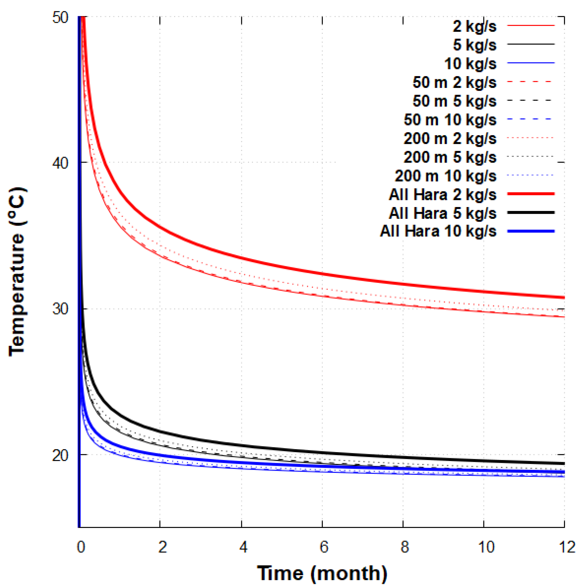
Figure 3 presents the vertical and radial directions used for the analysis of both patents. The implementation of graphite vertically along the wellbore, as proposed in [
29] has been varied from 50 to 200 m from the bottom depth of the DBHE and then for the whole length (All Hara). The influence of the horizontal extension of the enhanced conductive chamber described in the Buchi patent has been investigated for radii (r) of 50 cm, 1 m and 5 m with a constant vertical length of 30 m from the bottom of the DBHE. Its vertical extension has been varied from 30 to 100 m with a constant radial distance (r) of 50 cm.
The top of the theoretical reservoir models were set at 1 bar and 10
C, with a homogeneous rock porosity of 10 % and a permeability of 10
m
. The thermal properties of rocks are described in
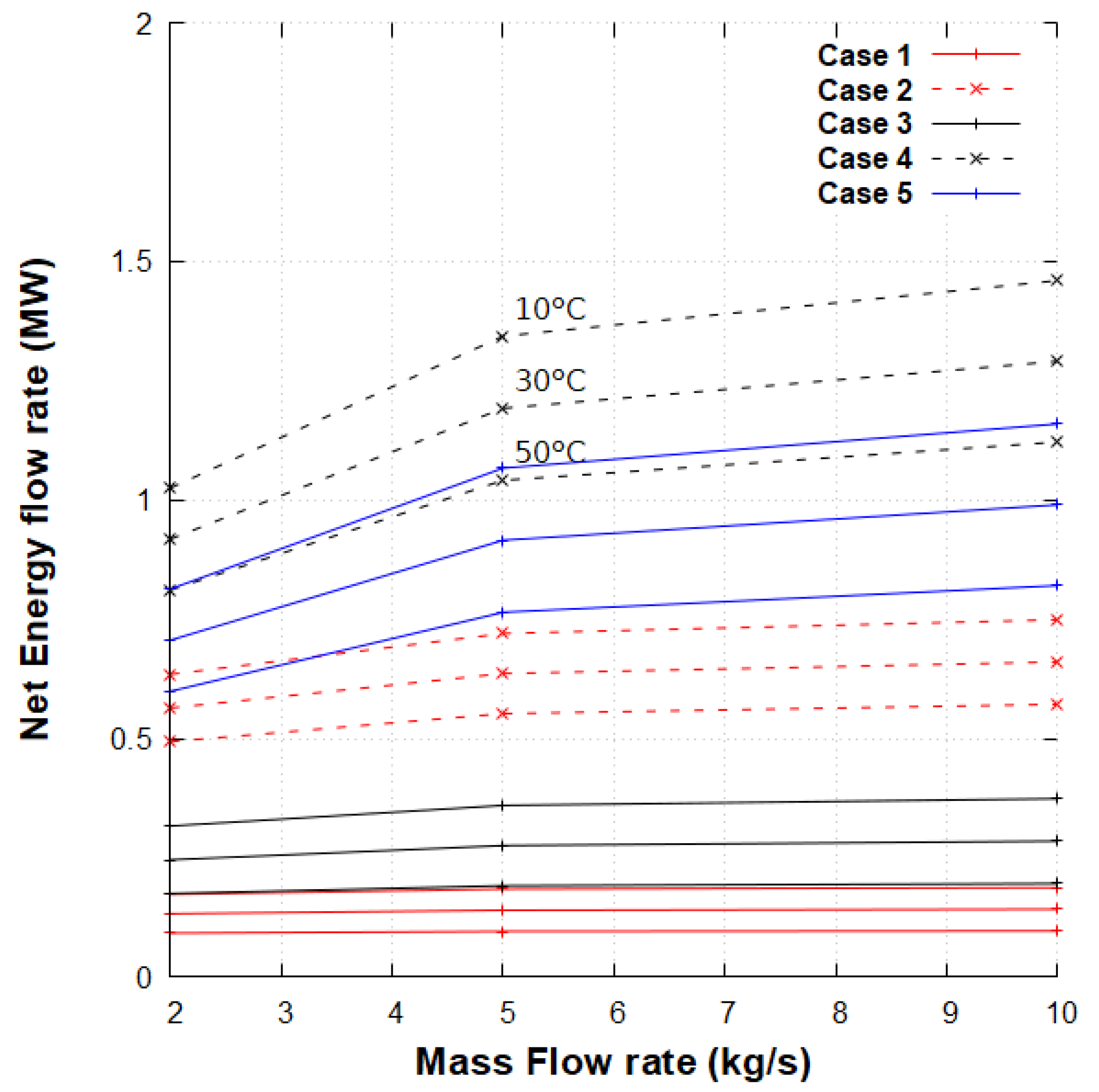
Table 1. The two patents have been compared for case 1 against the base case without graphite implementation. The most efficient and cost effective solution has been identified and tested for the remaining cases 2–5 described in
Table 2.
2.5. Case Study: Implementation of a DBHE in an EGS System
The Newberry Volcano site hosts a demonstration EGS to investigate low pressure stimulations and microseismicity monitoring [
3]. To obviate the stimulation process and still access the heat, a DCHE has been considered instead of the well NWG 55-29 in Newberry, using the well materials described in
Section 2.3. The wellbore is based on the NWG 55-29 well schematic from [
3] with the tubing diameter of 3 1/2” from [
14], and a vertical gap of 3 m between the bottom of the tubing and the bottom of the well (3067 m). It uses the initial temperature log in the well NWG 55-29, shown in
Figure 4, with 12
C at the surface.
The mesh was adapted with the formations shown in
Table 3, taken from a previous TOUGH2-based study [
38]; the density of the formations is 2700 kg/m
. The thermal influence of graphite on the wellbore has been studied and compared to a DCHE with a conventional material casing, as investigated in [
39].
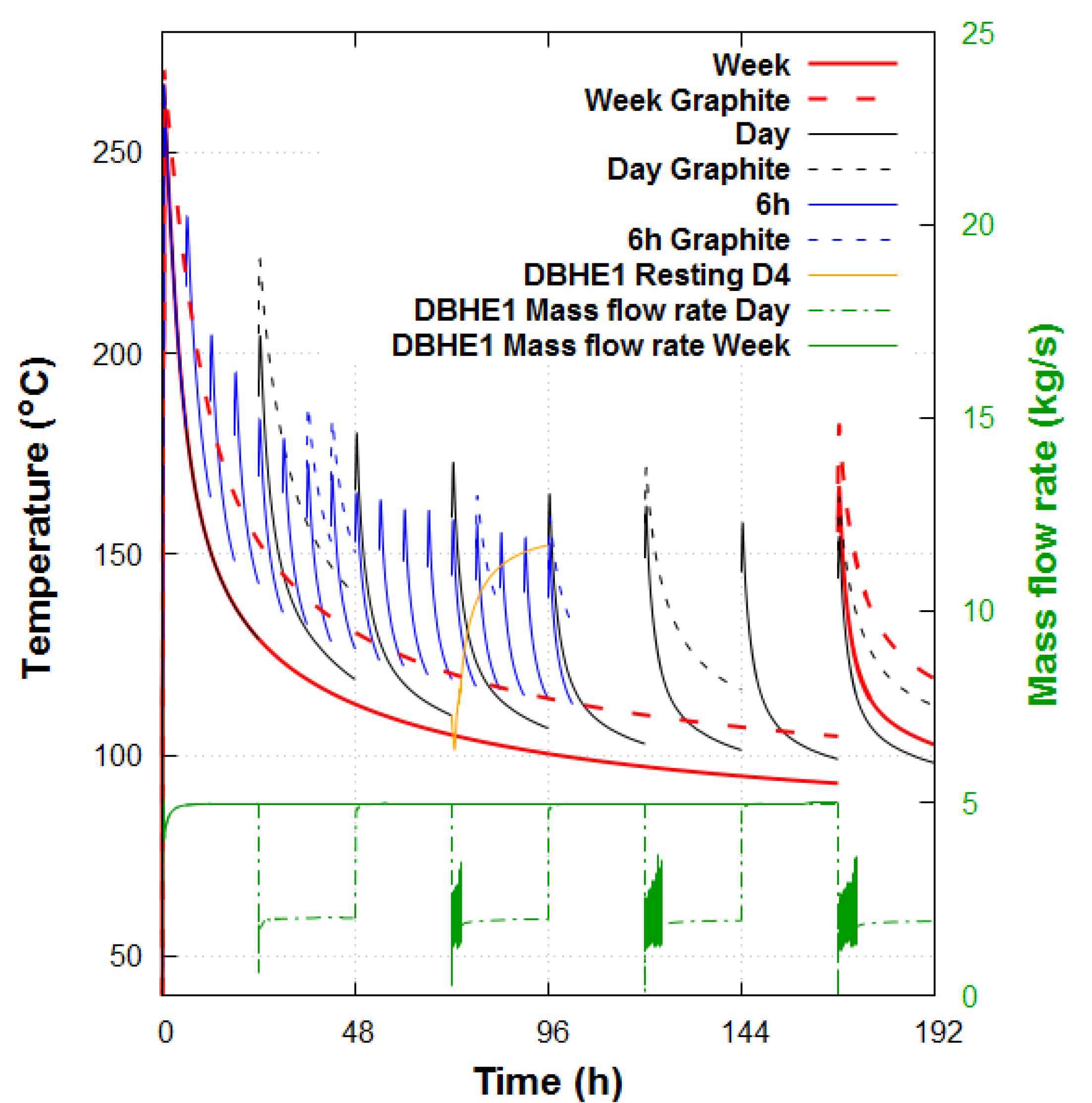
A 2D DBHE doublet model has been built to investigate the potential increase of the thermal performances due to production and loading cycles. Two identical DBHEs located 50 m apart in the Newberry volcano environment have been modelled. The 50 m distance was assumed to be sufficient to avoid a thermal breakthrough between the DBHEs considering the time of simulation (240 h).
Alternating imposed injections are considered in each DBHE for different periods: 6, 24 and 168 h. For the first period, water circulates at 5 kg/s in a DBHE (DBHE1), and the second DBHE (DBHE2) has no mass flow rate imposed (loading phase). In the following period, 5 kg/s is applied to DBHE2 while DBHE1 is under a loading phase.
4. Discussion
Our numerical assessment of highly conductive materials in DBHEs and innovative closed-loop well patents provides insights into their potential performances in various settings. In this work, the influence of alternating injection and resting periods for a DBHE with high-temperature gradient settings is shown to be non-negligible compared to DBHEs being a mean geothermal gradient such as in Weggis, Switzerland [
13]. The increase of the DBHE length in Newberry (3067 m) compared to the DBHE in Weggis (2295 m) can also explain this difference, due to the increase of the surface heat exchange. Further research on very short cycles can be pursued to target only the high-temperature peak and investigate whether the recovery period in high geothermal gradients is long enough to supply a sustainable amount of energy. The unconventional implementation of enhanced DBHEs [
32] needs further investigation close to a magmatic object with realistic heterogeneous geological formations, as in the IDDP-1 project [
44,
45], or in deeper zones, in crustal bodies [
46], to overcome the current technical limitations.
T2Well/EOS1 is a 1D wellbore simulator, which might encounter challenges when modeling real 3D flows in unconventional well geometries, such as the bottom of a DBHE. Despite the model validation obtained from an experimental study, the numerical model might provide inaccurate results for deeper DBHEs with other specific geological conditions and without experimental data. Multiphysics codes [
26,
28] can target the complex geometry in specific well sections to strengthen the heat performance analysis and the pressure loss assessments. Supercritical CO
and organic fluids can also be used to extract the heat from low permeable and high-temperature geothermal systems to counterbalance the high pressure losses using pure water, but with a high energy extraction rate [
18,
20]. As super hot EGS are targeted at accessing high temperatures—up to 450
C in Newberry [
47], 500
C for the DESCRAMBLE project in Italy [
48] and the Magma Test Bed in Iceland [
49], higher temperature capabilities need to be implemented in the current numerical modelling software and tools to investigate the wellbore-reservoir interactions.


