Abstract
Modern masonry structures, apart from having a load-bearing function, are more and more subjected to additional non-structural requirements related to, e.g., thermal insulation and moisture control. This has respectively led to the introduction of thermal break layers, in practice often executed using autoclaved aerated concrete (AAC) blocks, and damp proof courses (DPC) in masonry walls. These modifications have an impact on the mechanical characteristics of the masonry, such as the shear strength. In this paper, an extensive experimental campaign is therefore conducted on masonry triplets to investigate the initial shear strength of concrete block and clay brick masonry, including AAC blocks. The impact of the the presence of a polyethylene DPC layer is also studied. Moreover, the position of the DPC membrane is varied, i.e., directly on top of the brick (which is generally not recommended yet common in construction practice) and in the middle of the mortar joint. In total, 138 shear tests were performed according to the EN 1052-3 standard, with low to moderate precompression levels. The test results focus on the differences in friction angle, shear modulus, and friction coefficient. It is concluded that the presence of an AAC block decreases the initial shear strength to a value which is lower than the one assumed by Eurocode 6. Moreover, when adding a DPC membrane, the shear strength is reduced even further to almost zero, in particular when the membrane is not put in the middle of the mortar joint.
1. Introduction
Masonry structures are nowadays designed for a high thermal insulation level to reduce energy losses in buildings. Compared to concrete blocks or clay bricks, autoclaved aerated concrete (AAC) blocks have better insulating properties, but often at the cost of a lower density and hence of a lower compressive strength [1]. To prevent cold bridges in the wall-floor junction, the first layer of the inner leaf of a cavity wall consists of a thermal break layer, often in the form of such AAC blocks, with concrete blocks or clay bricks on top as can be seen in Figure 1. The AAC layer thus acts as a thermal break layer ensuring a continuity of the insulation of the wall and floor [2], which is shown by the red dashed line.

Figure 1.
Cutout view of a masonry wall with a DPC and thermal break layer.
On top of the AAC layer, a damp proof course (DPC) is placed to prevent water and moisture from entering or rising in the inner leaf of a cavity wall. If this damp propagation is not properly addressed, mold formation can occur inside the wall as well as degradation of the masonry units [3,4]. However, from a structural point of view, such a DPC layer comes at the cost of a lower adherence between the mortar and masonry units [5,6,7,8], resulting in planes of weakness [9]. In the literature, little experimental data are available regarding the shear strength of masonry walls including a combination of DPC and AAC layers. Therefore, this paper presents an experimental study on the shear behavior of such composite wall systems in which multiple parameters are varied: the unit’s material (concrete or clay), the mortar type and thickness in case of clay bricks (glued thin layer mortar (TLM) or a thicker general purpose mortar (GPM) layer), the precompression load, the presence of a DPC layer, and the positioning of such a layer (in the middle of the GPM layer or directly on top of the unit). To the best of the authors’ knowledge, such an extensive multi-parameter experimental campaign has not been performed before.
In a European standardization context, the standard EN 1052-3 [10] has been adopted as the standard laboratory test to characterize the shear strength for specimens without a DPC layer and has been adopted by multiple researchers [11,12,13,14,15,16,17,18,19,20]. For specimens with a DPC membrane, a second European standard, EN 1052-4 [21], is the recommended experiment for determining the the shear strength, using small wallets containing at least six units. However, for the sake of consistent comparison, EN 1052-3 is followed in this study for both specimens with and without a DPC layer. Both standards assume a Mohr–Coulomb friction law (Figure 2) to calculate the initial shear strength or cohesion, i.e., the shear strength when no normal (precompression) load is present. This law,
assumes a linear relationship between the shear stress and the normal stress , where is the cohesion and the friction angle from which the friction coefficient is calculated. When precompression levels reach a certain level, failure is governed by a compression cap where the specimen will not fail in shear but due to pore collapse.
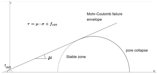
Figure 2.
Mohr–Coulomb failure envelope with compression cap. The symbols are explained in text.
Barrattucci et al. [12] carried out triplet tests on masonry units with different cement ratios subjected to monotonic and cyclic shear loadings. The failure modes largely depended on the applied precompression levels rather than the mortar composition. Mojsilović performed extensive research on different types of DPC membranes as well as their position [6]. Except for the bitumen-based DPC membrane, the influence of the DPC position was rather small for the obtained shear strength parameters. The initial shear strength, though, showed hardly any adherence between the mortar and DPC layer. Martens et al. [5] came to the same conclusions by performing experiments according to EN 1052-4 [21] using polyester-based DPC layers. They both suggested to use a characteristic initial shear strength of zero as a lower bound value.
To the knowledge of the authors, no research has been performed on the shear behavior of composite masonry consisting of a combination of DPC and AAC layers, while only limited research exists on the compressive behavior of this type of composite masonry. Deyazada [22] performed compressive tests on duplets and half-scale masonry panels consisting of an AAC layer with clay bricks or concrete blocks on top. A positive influence on the compressive strength was observed in the composite masonry compared to the one of masonry constructed using only the weakest material.
In the current paper, composite triplet specimens are tested in shear using the materials and test method described in the next section. Next, the results are shown and discussed in Section 3, in which also an evaluation is made on whether the assumed values in Eurocode 6 [23] for the initial shear strength and angle of internal friction are met.
2. Materials and Methods
2.1. Materials and Test Program
In the various setups in this experimental campaign, two different masonry clay units (Figure 3a,b), AAC blocks (Figure 3c) and concrete blocks (Figure 3d) are used in combination with or without a DPC membrane. The DPC used in the experiments is a polyethylene sheet with a thickness of 500 microns and an embossed diamond shape on both sides, resulting in a total DPC thickness of 1 mm. The two mortars applied for all experiments are a general purpose mortar (GPM) which was a ready-mix mortar for most experiments (strength class M5), and a thin layer mortar (TLM) for the clay bricks with the highest tolerances and smallest range according to EN 771-1 [24]. Table 1 shows the characteristics for all employed materials.
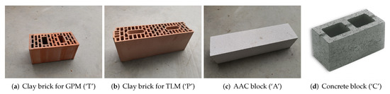
Figure 3.
Masonry units used in the experiments and their respective symbols within brackets.

Table 1.
Material properties.
The experiments are denoted by a coding system based on the structure
in which and refers, respectively, to the units on the outside and center of the triplet, see Figure 3 and Table 1. The type of mortar used is indicated by the third symbol , and indicates the use of a DPC layer. If the latter is placed directly on top of the outer units (so not sandwiched within the mortar layer), shows a ‘U’ to indicate this. Finally, refers to the precompression level and N indicates the replica number of the respective test (1 up to 3 or 4); see Table 2.
Table 2.
Tested series and respective precompression levels. The coding of the configurations are explained in text.
Most of the experiments are tested with a GPM (denoted with an ‘N’ as the third symbol) with a joint thickness of around 14 mm. Only the ‘PPG’ series (i.e., specimens constructed using only perforated clay bricks with tongue and groove (‘P’), using thin layer mortar joints (‘G’)) are tested with a TLM where the bed joint thickness is about 1 mm. When combining AAC blocks with clay bricks or concrete blocks, using a GPM is generally recommended by manufacturers.
For each series, three different precompression levels are used, and for each precompression level, three or four tests are performed. This makes a total of 138 experiments of which a summary of all tested configurations is shown in Table 2.
2.2. Test Setup and Method
As mentioned in the introduction, due to the combination of shear tests with and without DPC layers, the authors decided to perform all experiments according to the EN 1052-3 standard [10] instead of following EN 1052-4 [21], which is specifically targeted to specimens with a DPC layer. Prior to testing, the units are stored and cured for at least 28 days. Except for the ‘PPND’ specimens, the clay, concrete, and AAC units are cut to the maximum length of 300 mm as described in the standard. After curing, the samples are rotated 90° by hand and placed in the test setup shown in Figure 4. Due to a weak adhesion between the DPC and mortar, this connection was already damaged for some specimens prior to testing, which is indicated in Table 3 by a ‘Y(es)’ or ‘1’ (delamination in one joint).
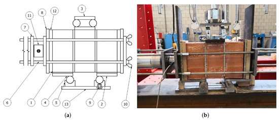
Figure 4.
Triplet test setup: (a) schematic overview with (1) cardboard layer, (2) and (4) bottom steel plates, (3) top steel plate, (5) steel rollers, (6) steel rods, (7) and (8) steel plates, (9) adjusting screw for the bottom roller, (10) steel nuts, (11) load cell, (12) fiberboard plate, (13) steel base plate; (b) picture of the actual setup.
Table 3.
Mean values of the test results. The abbreviations are explained in text.
After the specimen is placed in the testing machine, two fiberboard plates are placed adjacent to it for a better transfer of the precompression load, shown by number 12 in Figure 4a. Behind the fiberboard plates, steel plates (indicated by number 7 and 8) are placed to transfer the precompression load. A load cell (11) with a wire potentiometric transducer (PPT) measures the precompression force and displacement applied by the horizontal hydraulic jack. Cardboard (1) is placed between the bricks and steel plates (2) to create a better surface contact. The same is used on top of the center brick. The position of the steel rollers (5) is decided according to the recommendations provided in EN 1052-3 [10], and the top steel plate (3) is placed where the shear load is applied by a second hydraulic jack together with a load cell and a PPT to measure the shear displacement.
At the start of each test, the precompression load is applied (as listed in Table 2), after which the shear load is increased monotonically with a speed of around 2.5 N/mm/min until failure occurs. The observed failure modes can be sliding of the bed-joints (indicated with mode ‘S’, Figure 5a), crushing (pore collapse) of the bricks (mode ‘C’, Figure 5b), or a combination of both (mode ‘M’, Figure 5c). The respective precompressions levels vary for each test series since they are adjusted to obtain sliding as the preferred failure mode, in order to construct a Mohr–Coulomb curve (Equation (1)).
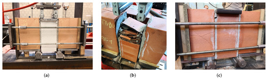
Figure 5.
Examples of failure modes of the specimens. (a) Sliding of the brick, mode ‘S’ (PAN-03-1); (b) Crushing of the brick, mode ‘C’ (TTNDU-05-1); (c) Mixed failure of the brick, mode ‘M’ (TTN-01-2).
3. Results and Discussion
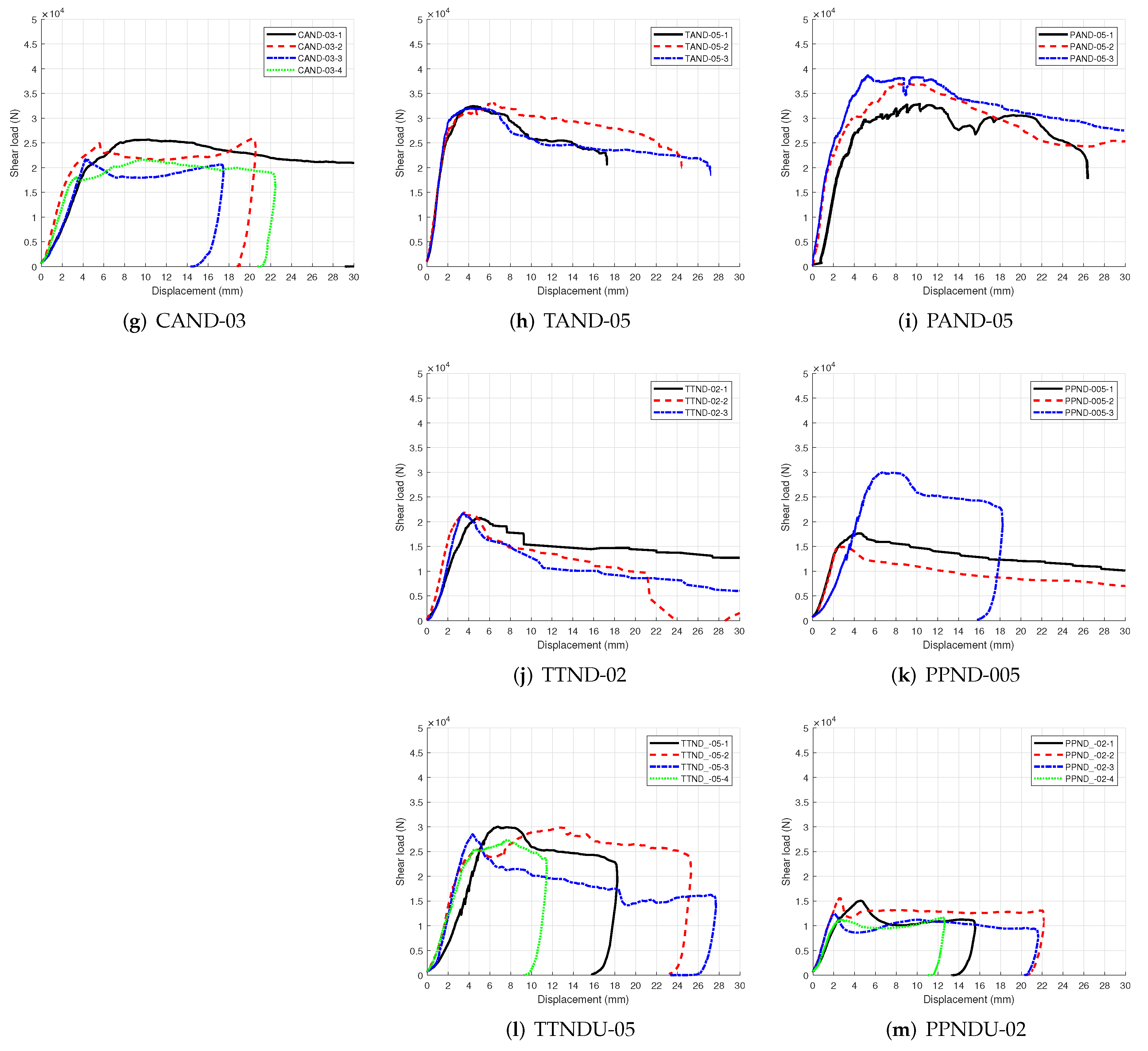
Figure 6 shows the obtained force-displacement curves for a selection of the executed experiments. The first column shows all concrete specimens (‘C’), whereas the center column lists all specimens using clay bricks without tongue and groove (‘T’) and general purpose mortar, and the last column displays the specimens using clay bricks with tongue and groove (‘P’) and either TLM (for specimens without AAC and DPC layers) or GPM. The homogeneous concrete specimens (‘CCN’, Figure 6a) and the clay brick samples with TLM (‘PPG’, Figure 6c) show a more brittle failure behavior than the specimens with clay bricks using GPM (‘TTN’, Figure 6b). The brittleness decreases for all samples when an AAC block is placed in the middle (‘CAN’ (Figure 6d), ‘TAN’ (Figure 6e), and ‘PAN’ (Figure 6f)), and appears to be the lowest when a DPC layer is added (‘CAND’ (Figure 6g), ‘TAND’ (Figure 6h), and ‘PAND’ (Figure 6i)). The sudden drop after the peak load of the concrete specimens (Figure 6a), which indicates a brittle failure, remains visible for all precompression levels. However, at low precompression levels, sliding failure occurs at the mortar–brick interface, whereas at higher precompression levels, sliding failure occurs with cracking within the mortar joints. Figure 5c shows a specimen with clay bricks at a higher precompression level. These specimens crush internally before/during sliding, thus leading to a mixed failure mode. The triplet tests with the AAC layer (Figure 6d–f) always slid between the AAC layer and the mortar, whereas with higher precompression levels, the AAC was scratched or crushed.
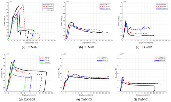
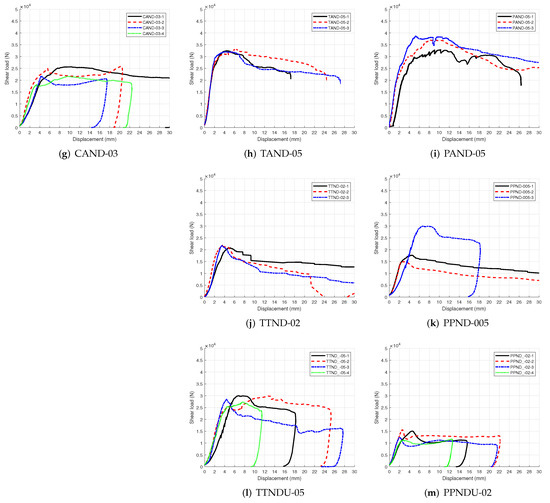
Figure 6.
Load-displacement curves of a selection of the executed tests. The first column shows all concrete specimens (‘C’), the center column lists all specimens using clay bricks without tongue and groove (‘T’) and the last column displays the specimens using clay bricks with tongue and groove (‘P’).
Handling and setting up specimens with a DPC layer, in particular the ones with a DPC layer put directly on top of the units, was challenging due to a lack of adhesion between the DPC layer and the rest of the specimen (this can be seen in Figure 5b). This resulted in excluding two experiments from the TTNDU-03 series since their respective shear strengths were six times lower than the other experiments of that series. At low precompression levels, the remaining specimens fail in sliding whereas at higher precompression levels, crushing of the center brick occurs with sliding afterwards (Figure 5b).
As can be seen from Figure 6 all specimens behave quasi-linear elastically at the beginning of the curve, followed by various possible nonlinear behaviors:
- The peak load is followed by a sudden drop, after which then the center unit starts sliding at a constant load (Figure 6a,c,d,f).
- Softening behavior occurs after reaching the peak load, but still with a considerable drop. This is the case when internal cracking is happening before sliding (Figure 6b,h,j).
- Softening behavior occurs after reaching the peak load, but no considerable drop occurs, only sliding at the maximum load level. A small smooth drop might occur due to differences in thickness of the mortar joint (Figure 6g,i,k–m).
- A first crack occurs already in the linear elastic part on one side of the center unit. The curve continues with a lower stiffness until one of the aforementioned failure modes takes place (Figure 6e).
Table 3 shows the mean values of the maximum shear stress and precompression stress. These are thus the mean values of the test repetitions recorded for every precompression level of every setup. The position of the DPC layer resulted in different failure modes. When it is placed at the bottom of a mortar joint (indicated with a ‘U’ in the specimen’s name), the layer lays ‘dry’ on the surface of the brick, and the maximum shear strength is significantly lower. This position of the DPC is often implemented in practice because of convenience since no double mortar layer is required to ‘sandwich’ the DPC membrane, yet this is against the recommendations of DPC manufacturers. The maximum recorded values for the specimens without an AAC block were higher than those with an AAC block, and the presence of a DPC layer decreased the maximum shear stress even more. The bed joints from the specimens were not always intact before testing (indicated in the third column of Table 3), and this influenced the results. The last column of the table shows the different failure modes recorded during the experiments.
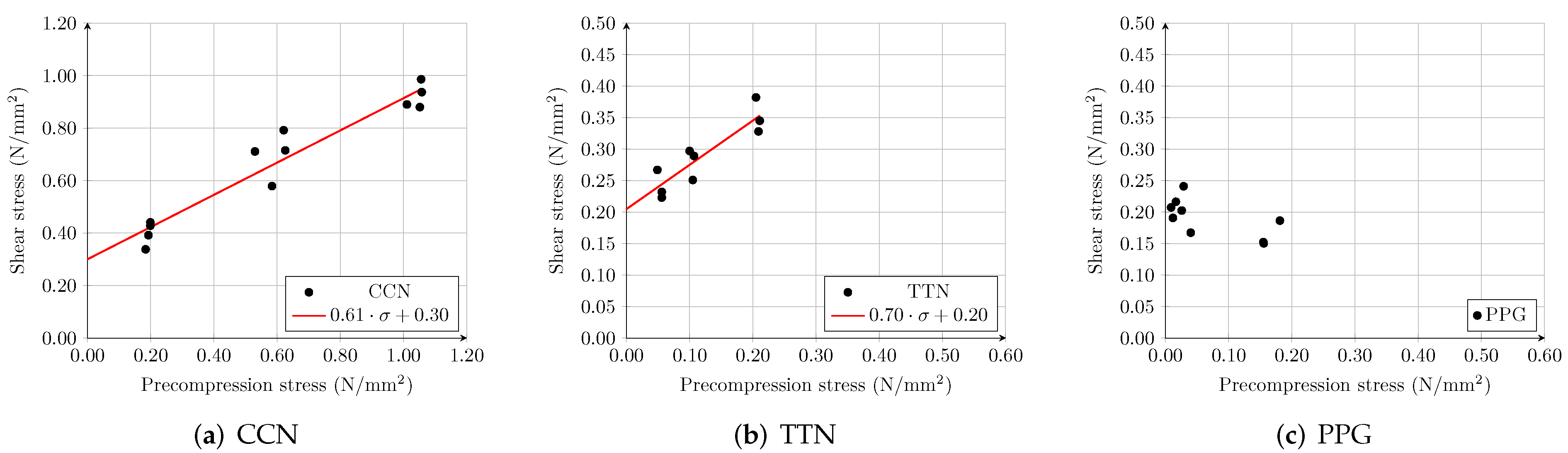
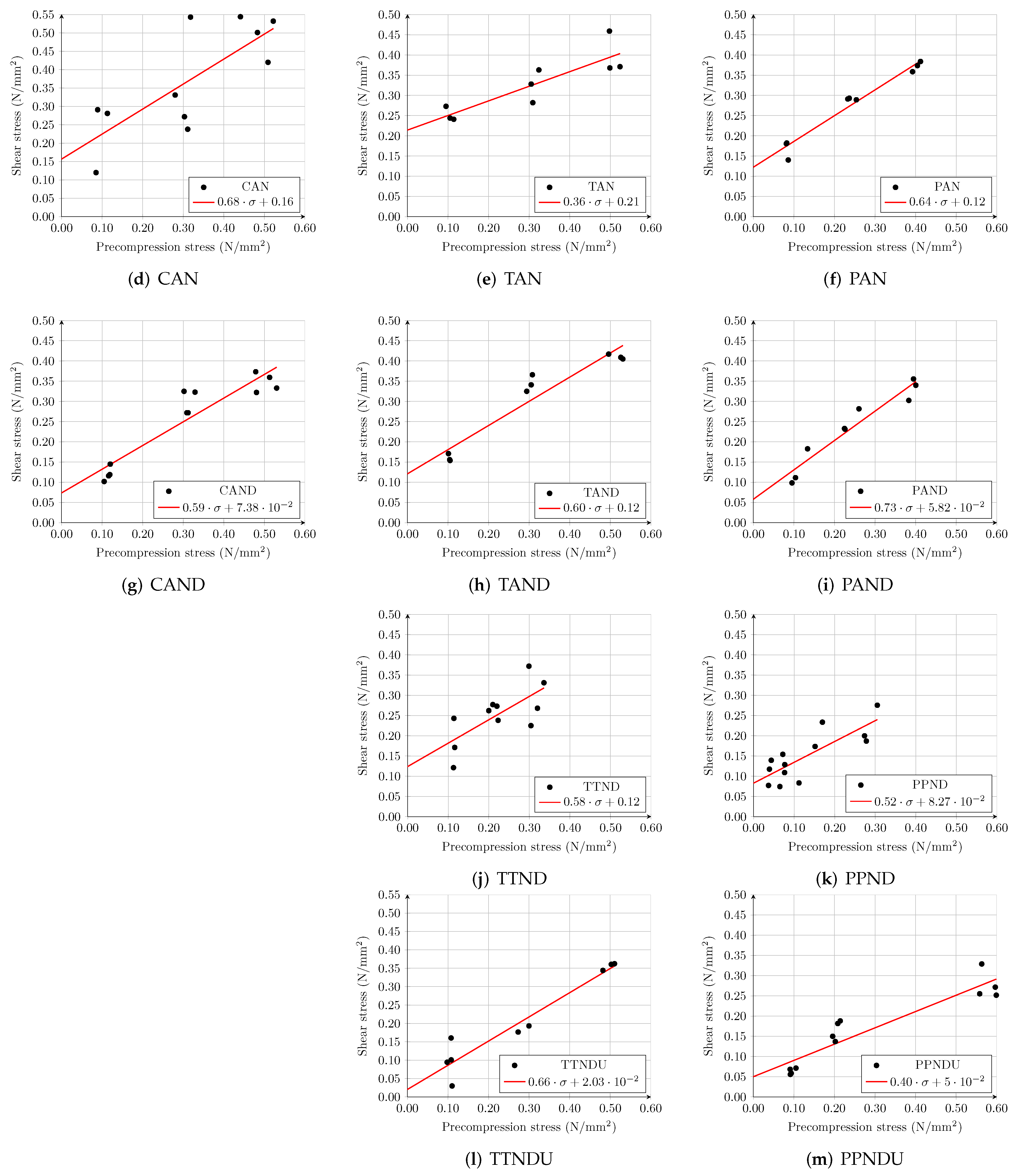
All Mohr–Coulomb curves from the experiments can be seen in Figure 7. The curves with the concrete blocks show the highest initial shear strength, and different scales were needed to indicate the complete scatter of the concrete specimens. The Mohr–Coulomb curve from the ‘PPG’-specimens could not be drawn because the samples did not fail in sliding but a combination of crushing (i.e., pore collapse of the center unit) and sliding, even at very low precompression levels. The scatter from this graph does, however, show a mean initial shear strength of around 0.20 MPa.
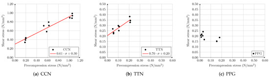
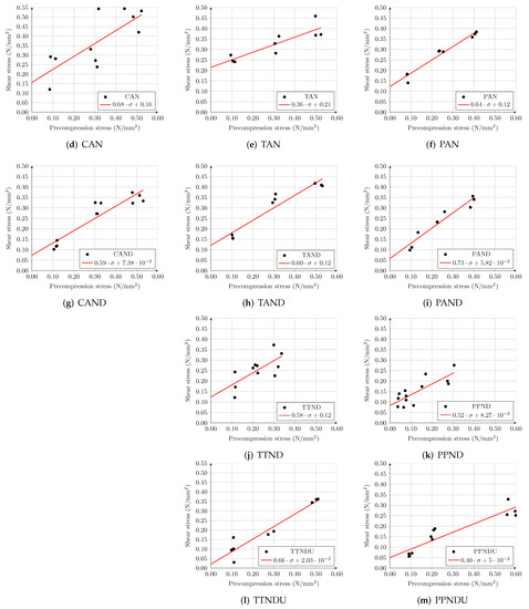
Figure 7.
Mohr–Coulomb curves to determine the mean initial shear strength and friction coefficient. The first column shows all concrete specimens (‘C’), the center column lists all specimens using clay bricks without tongue and groove (‘T’) and the last column displays the specimens using clay bricks with tongue and groove (‘P’).
All the results from the Mohr–Coulomb curves (Figure 7) are combined in Table 4, converted to characteristic values by multiplying them by 0.8 [10], and compared with the default characteristic values given by Table 3 and Table 4 in Eurocode 6 (which are values for homogeneous and not composite walls) [23]. Except for the ‘TAN’ and ‘PPNDU’ specimens, all friction coefficients comply with Eurocode 6. The initial shear strengths are, however, always lower than the default values from the standard, except for the homogeneous concrete specimens (‘CCN’). The specimens with a DPC layer exhibit hardly any initial shear strength, and therefore, it is recommended to use an initial shear strength of zero. These results are also confirmed by other researchers [5,6]. The ‘PPG’ specimens show a characteristic initial shear strength of ±0.16 MPa, again lower than the Eurocode 6 value. These specimens failed in crushing or crushing with sliding and did not follow a Mohr–Coulomb friction law, i.e., no friction coefficient could be determined, as can be seen in Figure 7c. Therefore, this result might not be an accurate representation of the initial shear strength. A solution to obtain sliding as the failure mode can be achieved by testing the triplets in the out-of-plane transversal direction instead of the in-plane transversal one.
Table 4.
Comparison of the characteristic initial shear strength and friction coefficient with the ones of Eurocode 6. The values highlighted in green comply with the minimum values of the Eurocode, whereas the ones highlighted in red do not.
4. Conclusions
In this paper, an experimental campaign was conducted to investigate the shear behavior of composite masonry. The novelty of this contribution is the large set of parameters which were taken into account, resulting in a total of 138 experiments. In the reported study, AAC blocks and DPC layers were used in combination with clay and concrete masonry. Moreover, two types of mortar were used, and also the position of the DPC layer was varied. A comparison of the experimental results allowed for drafting the following conclusions:
- In general, the maximum shear strength of the specimens decreased when an AAC block was added (a reduction of 40–47%, except for clay bricks with GPM, which showed no reduction) and was even lower in combination with a DPC layer placed in the middle of the joint (a reduction of 40–77%). Additionally, the position of the DPC layer also has a major influence: a reduction of the initial shear strength of 75% up to 90% was observed when not placing the membrane in the middle. It is therefore not recommended to place a DPC layer directly on top or at the bottom of a mortar joint, as is commonly done in practice, but to place the membrane in the middle of the joint (i.e., ‘sandwiched’).
- The resulting initial shear strengths and friction coefficient are compared with the default values given in Eurocode 6 [23]. Except for the homogeneous concrete specimens, the characteristic initial shear strength never meets the respective default value of the standard. On the other hand, except for two configurations, all friction coefficients comply with Eurocode 6.
- DPCs show hardly any adherence between the brick or the mortar. These layers form planes of weakness, and a characteristic initial shear strength of zero should be adopted, confirming earlier observations [5,6].
Author Contributions
Conceptualization, M.V., H.D. and B.V.; Methodology, M.V., H.D. and B.V.; Validation, M.V., H.D. and B.V.; Formal Analysis, M.V. and R.D.; Investigation, M.V.; Resources, H.D. and B.V.; Data Curation, M.V.; Writing—Original Draft Preparation, M.V.; Writing—Review and Editing, R.D., H.D. and B.V.; Visualization, M.V.; Supervision, H.D. and B.V.; Project Administration, B.V.; Funding Acquisition, H.D. and B.V. All authors have read and agreed to the published version of the manuscript.
Funding
Part of this research was funded by the VLAIO TETRA InnoMaso project, project number HBC.2018.0053.
Data Availability Statement
The data presented in this study are available on request from the corresponding author. The data are not publicly available due to the fact that it is part of an ongoing research.
Acknowledgments
The authors would like to thank the assistance of students Dries Eerdekens, Juul Jansen and Tom Weetjens during the experiments.
Conflicts of Interest
The authors declare no conflict of interest.
Abbreviations
The following abbreviations are used in this manuscript:
| AAC | Autoclaved Aerated Concrete |
| CAN | Specimens constructed using hollow concrete blocks (‘C’) and an AAC block (‘A’), |
| using general purpose mortar (‘N’) | |
| CAND | CAN specimens including a damp proof course in the middle of the joints (‘D’) |
| CCN | Specimens constructed using hollow concrete blocks (‘C’) using general purpose |
| mortar (‘N’) |
| DIN | German Institute for Standardisation |
| DPC | Damp Proof Course |
| EN | European Standard |
| GPM | General Purpose Mortar |
| PAN | Specimens constructed using perforated clay bricks with tongue and groove (‘P’) |
| and an AAC block (‘A’), using general purpose mortar (‘N’) | |
| PAND | PAN specimens including a damp proof course in the middle of the joints (‘D’) |
| PPG | Specimens constructed using only perforated clay bricks with tongue and groove (‘P’), |
| using thin layer mortar (‘G’) | |
| PPN | Specimens constructed using only perforated clay bricks with tongue and groove (‘P’), |
| using general purpose mortar (‘N’) | |
| PPND | PPN specimens including a damp proof course in the middle of the joints (‘D’) |
| PPNDU | PPN specimens including a damp proof course put directly on top of the bricks (‘DU’) |
| PPT | Potentiometric Transducer |
| RILEM | The International Union of Laboratories and Experts in Construction Materials, |
| Systems and Structures | |
| TAN | Specimens constructed using perforated clay bricks without tongue and groove (‘T’) |
| and an AAC block (‘A’), using general purpose mortar (‘N’) | |
| TAND | TAN specimens including a damp proof course in the middle of the joints (‘D’) |
| TLM | Thin Layer Mortar |
| TTN | Specimens constructed using only perforated clay bricks without tongue and groove |
| (‘T’), using general purpose mortar (‘N’) | |
| TTND | TTN specimens including a damp proof course in the middle of the joints (‘D’) |
| TTNDU | TTN specimens including a damp proof course put directly on top of the bricks (‘DU’) |
References
- Ferretti, D.; Michelini, E.; Rosati, G. Mechanical characterization of autoclaved aerated concrete masonry subjected to in-plane loading: Experimental investigation and FE modeling. Constr. Build. Mater. 2015, 98, 353–365. [Google Scholar] [CrossRef]
- National Concrete Masonry Association. Thermal Bridges in Wall Construction; Technical Report; National Concrete Masonry Association: Herndon, DC, USA, 2010. [Google Scholar]
- Veas, L. Development and Application of a Methodological Model that Allows Evaluate and Compare the Behaviour of External Walls Exposed to Moisture Phenomenons. Ph.D. Thesis, Université Catholique de Louvain, Ottignies-Louvain-la-Neuve, Belgium, 2006. [Google Scholar]
- Kharseh, M.; Ostermeyer, Y.; Nägeli, C.; Kurkowska, I.; Wallbaum, H. Humid Wall: Review on Causes and Solutions. In Proceedings of the World Sustainable Built Environment Conference, Hong Kong, China, 5–7 June 2017; Volume Practices & Policies for High-Performance Buildings. p. 8. [Google Scholar]
- Martens, D.; Bertram, G. Shear strength of clay brick masonry including damp proof course. In Proceedings of the 14th Brick/Block Masonry Conference, Sydney, Australia, 17–20 February 2008. [Google Scholar]
- Mojsilović, N. Masonry elements with damp-proof course membrane: Assessment of shear strength parameters. Constr. Build. Mater. 2012, 35, 1002–1012. [Google Scholar] [CrossRef]
- Denys, N.; Op’t Roodt, G. De Invloed van Akoestische Isolatie, een Waterkerende Laag en Hechtingsmiddelen op de Afschuifweerstand van Metselwerkconstructies. Master’s Thesis, Hasselt University and KU Leuven, Hasselt, Belgium, 2018. [Google Scholar]
- Totoev, Y.Z.; Simundic, G. Shear transfer capacity of alternative materials for horizontal slip joints in masonry. In Proceedings of the 15th Brick/Block Masonry Conference, Florianopolis, Brazil, 3–6 June 2012; p. 9. [Google Scholar]
- Ferretti, F.; Ferracuti, B.; Mazzotti, C.; Savoia, M. Destructive and minor destructive tests on masonry buildings: Experimental results and comparison between shear failure criteria. Constr. Build. Mater. 2019, 199, 12–29. [Google Scholar] [CrossRef]
- CEN—European Committee for Standardization. EN 1052-3: Methods of Test for Masonry-Part 3: Determination of Initial Shear Strength; CEN—European Committee for Standardization: Brussels, Belgium, 2002. [Google Scholar]
- van der Pluijm, R. Shear behaviour of bed joints. In Proceedings of the 6th North American Masonry Conference, Philadelphia, PA, USA, 6–9 June 1993; pp. 125–136. [Google Scholar]
- Barattucci, S.; Sarhosis, V.; Bruno, A.W.; D’Altri, A.M.; de Miranda, S.; Castellazzi, G. An experimental and numerical study on masonry triplets subjected to monotonic and cyclic shear loadings. Constr. Build. Mater. 2020, 254, 119313. [Google Scholar] [CrossRef]
- Cavalheiro, O.; Pedroso, G. Experimental data on hollow block prisms using direct shear tests. In Proceedings of the 12th Brick/Block Masonry Conference, Madrid, Spain, 25–26 June 2000. [Google Scholar]
- Lourenço, P.B.; Barros, J.O.; Oliveira, J.T. Shear testing of stack bonded masonry. Constr. Build. Mater. 2004, 18, 125–132. [Google Scholar] [CrossRef] [Green Version]
- Pasquantonio, R.D.; Parsekian, G.A.; Fonseca, F.S.; Shrive, G.N. Experimental and numerical characterization of the interface between concrete masonry block and mortar. Rev. IBRACON Estruturas Mater. 2020, 13, 578–592. [Google Scholar] [CrossRef]
- Vanheukelom, M.; Vandoren, B.; Dragan, D.; Degee, H. Shear behavior of masonry triplets with damp proof course and thermal insulating layer. Brick and Block Masonry-From Historical to Sustainable Masonry. In Proceedings of the 17th International Brick/Block Masonry Conference, Kraków, Poland, 5–8 July 2020; pp. 334–340. [Google Scholar] [CrossRef]
- Vermeltfoort, A.A.; Martens, D. Variation in mechanical properties of mortar and masonry. In Proceedings of the 11th Canadian Masonry Symposium, Toronto, ON, Canada, 31 May–3 June 2009. [Google Scholar]
- Yalamanchili, K.; Anand, S. Shear Strength of Mortar Joints in Masonry: A Review. In Proceedings of the 5th Canadian Masonry Symposium, Vancouver, BC, Canada, 5–7 June 1989; Volume 2, p. 7. [Google Scholar]
- Tandon, R.; Maharjan, S.; Gautam, S. Shear and tensile bond strengths of autoclaved aerated concrete (AAC) masonry with different mortar mixtures and thicknesses. J. Eng. Issues Solut. 2021, 1, 20–31. [Google Scholar] [CrossRef]
- Balasubramanian, S.; Kanchi, B.; Prasad, M.; Goswami, R. A comprehensive test procedure for determination of shear strength parameters of brick masonry specimens. J. Struct. Eng. 2019, 46, 395–405. [Google Scholar]
- CEN—European Committee for Standardization. EN 1052-4: Methods of Test for Masonry-Part 4: Determination of Shear Strength Including Damp Proof Course; CEN—European Committee for Standardization: Brussels, Belgium, 2000. [Google Scholar]
- Deyazada, M.; Vandoren, B.; Dragan, D.; Degée, H. Experimental investigations on the resistance of masonry walls with AAC thermal break layer. Constr. Build. Mater. 2019, 224, 474–492. [Google Scholar] [CrossRef]
- CEN—European Committee for Standardization. EN 1996-1-1-Design of Masonry Structures-Part 1-1: General Rules for Reinforced and Unreinforced Masonry Structures; CEN—European Committee for Standardization: Brussels, Belgium, 2005. [Google Scholar]
- CEN—European Committee for Standardization. EN 771-1: Specification for Masonry Units-Part 1: Clay Masonry Units; CEN—European Committee for Standardization: Brussels, Belgium, 2011. [Google Scholar]


Publisher’s Note: MDPI stays neutral with regard to jurisdictional claims in published maps and institutional affiliations. |
© 2021 by the authors. Licensee MDPI, Basel, Switzerland. This article is an open access article distributed under the terms and conditions of the Creative Commons Attribution (CC BY) license (https://creativecommons.org/licenses/by/4.0/).