Article

Efficiency Enhancement of an Ammonia-Based Solar Thermochemical Energy Storage System Implemented with Hydrogen Permeation Membrane

1
College of Mechanical Engineering, Zhejiang University of Technology, Hangzhou 310032, China
2
Institute of Engineering Thermophysics, Chinese Academy of Sciences, Beijing 100049, China
3
School of Engineering Science, University of Chinese Academy of Sciences, No. 19(A) Yuquan Road, Beijing 100049, China
*
Author to whom correspondence should be addressed.
Sustainability 2021, 13(22), 12783; https://doi.org/10.3390/su132212783
Submission received: 30 July 2021 / Revised: 4 November 2021 / Accepted: 11 November 2021 / Published: 19 November 2021

Abstract

:
The ammonia-based solar thermochemical energy storage (TCES) is one of the most promising solar TCESs. However, the solar-to-electric efficiency is still not high enough for further commercialization. The efficiency is limited by the high ammonia decomposition reaction temperature, which does not only increase the exergy loss through the heat recuperation but also causes a large re-radiation loss. Nonetheless, lowering the reaction temperature would impact the conversion and the energy storage capacity. Thanks to the recent development of the membrane technology, the hydrogen permeation membrane has the potential to enhance the conversion of ammonia decomposition under the moderate operating temperature. In this paper, an ammonia-based solar thermochemical energy storage system implemented with hydrogen permeation membrane is proposed for the first time. The system model has been developed using the Aspen Plus software implemented with user-defined Fortran subroutines. The model is validated by comparing model-generated reactor temperatures and conversions profiles with data from references. With the validated model, an exergy analysis is performed to investigate the main exergy losses of the system. Furthermore, the effects of the membrane on system efficiency improvement are studied. The results show that exergy loss in the charging loop is dominant, among which the exergy losses of Heat Exchanger Eh,A, together with that of the re-radiation Er, play important roles. Compared with the conventional system, i.e., the system without the membrane, the Eh,A and Er of the proposed system are more than 30% lower because the hydrogen permeation membrane can improve ammonia conversion at a lower endothermic reaction outlet temperature. Consequently, the proposed system, presumably realized by the parabolic trough collector at ~400 °C, has a theoretical solar-to-electric efficiency of ηste, which is 4.4% higher than the conventional ammonia-based solar thermochemical energy storage system. Last but not least, the efficiency is 3.7% higher than that of a typical parabolic trough solar power plant, which verifies the thermodynamic feasibility of further commercialization.

1. Introduction

Due to the increasingly serious climate change, renewable energy resources, as sustainable alternatives to fossil fuels, are promising to achieve the Paris Agreement [1,2]. Compared with the other primary renewable energy resources including wind, tidal, and geothermal energy, solar energy is abundant and prevalent [3,4]. Solar applications mainly comprise photovoltaics (PV) and concentrating solar power (CSP). Although PVs have experienced a higher deployment, CSP exhibits priorities in centralized electricity generation with the storage to overcome the inherent problem of intermittency [5,6,7], i.e., the CSP incorporated with thermal energy storage (TES) at large scale can provide dispatchable renewable electricity. TES is mainly classified into sensible, latent, and thermochemical energy storage. Sensible thermal energy storage (STES) systems store energy through temperature changes experienced by the storage medium. To date, STES is considered as a mature technology installed in commercial concentrating solar power plants, e.g., Gemasolar, Andasol-1, and PS10 solar power plants [8,9]. Latent thermal energy storage (LTES) utilizes the latent heat involved in a phase change, which can achieve a higher energy density than the STES. However, the LTES is limited by the complex and insufficient heat transfer processes [10]. Thermochemical energy storage (TCES) absorbs and releases heat by carrying out endothermic and exothermic reactions, respectively. Compared to sensible and latent thermal energy storage systems, the TCES has advantages of higher energy storage densities and ideally no losses for long-term storage [11,12]. There are lots of reactions being investigated for the TCES, which can be commonly classified into six systems including carbonate, metal hydrides, hydroxides, metal oxides, organic, and ammonia systems [13].
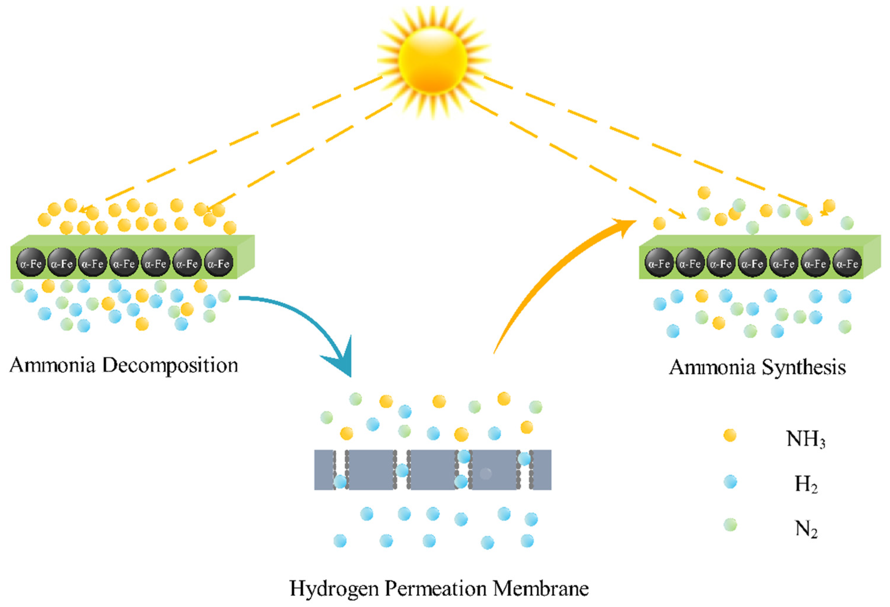
The carbonation/decarbonation reactions, e.g., MgO/MgCO3 and CaO/CaCO3, are attractive due to their relatively high operating temperatures (typically over 800 °C), high energy densities (~1800 kJ/kg), low operating pressures, and abundant availability of nontoxic carbonates minerals [5,11]. However, the carbonation/decarbonation reaction has the drawbacks of low reversibility and particle agglomeration/sintering, which might cause the partial deactivation and impact conversion [14]. Recently, the reversibility of the reaction was improved by using a molten salt eutectic, i.e., the good reversibility of natural dolomites has been obtained by using a NaCl and MgCl2 mixture due to the anti-agglomeration effect of impurities [15]. However, the methods are still limited to the bench-top demonstration. Metal hydrides with higher energy densities (~2800 kJ/kg) have been applied for the hydrogen storage devices of vehicles in a small scale to manage waste heat on board [16]. However, they commonly suffer from slow absorption kinetics and low thermal conductivity, e.g., the thermal conductivity of MgH2 is 1 Wm−1 K−1 [17,18]. The thermal conductivities of some metal hydrides, e.g., titanium hydride, can be improved by adding graphite [19,20]. Nonetheless, there has not been much research progress made in improving the reaction kinetics. The hydroxides, e.g., calcium hydroxide and magnesium hydroxide, which have similar energy densities to the carbonates, are commonly cheap, abundant, nontoxic, and have better reversibility [21,22]. The hydroxides system, especially the Ca-based hydroxides system, has reached a certain level of maturity with research efforts on improving reactor configuration and material mechanical properties [23]. However, the medium reaction temperatures might constrain its applicability in advanced CSP plants with higher operating temperatures [5]. Many metal oxides including BaO2 [24], Co3O4 [25], and perovskites ABO3 [26] have been investigated for solar TCES. Their energy densities are relatively lower than other gas−solid reactions. Recently, there has been much research conducted in materials aspects, reactor concepts, and their integration in CSP plants for metal oxides [27]. Nevertheless, they shared the same drawback of the poor heat and mass transfer performance. Materials kinetics and multicycle chemical stability are still required to be further enhanced for process upscaling [5]. Methane reforming reaction with H2O/CO2 is promising with high energy densities and operating temperatures. However, both reforming reactions are accompanied by an undesired side reaction, i.e., the water gas shift (WGS) reaction. Additionally, the expensive noble metal catalysts are required for the reactions, which might affect the techno-economic viability. On the other hand, there have been extensive investigations on using solar irradiated receivers to drive the methane reforming reaction [28,29], while the experiments on methanation reaction are limited. Without any side reactions, the ammonia-based solar TCES is promising with the priorities of sufficient heat and mass transfer and automatic phase separation of reactants and products. Figure 1 shows a schematic of a typical ammonia-based solar TCES. In the charging loop, ammonia (NH3) is dissociated into N2 and H2 endothermically by absorbing concentrated solar power. In the discharging loop, the stored energy can be recovered on demand by utilizing the exothermic reaction, i.e., ammonia synthesis reaction, to heat a working fluid, e.g., sCO2, for power generation.
Recently, the feasibility of both charging [30,31] and discharging loops [32] of the ammonia-based solar TCES have been validated experimentally. Additionally, the techno-economic viability of the system has been proved, i.e., the capital cost is estimated to be less than USD 15/kWh [33]. Nonetheless, the highest solar-to-electric conversion efficiency of the ammonia-based solar TCES ever reported is only 18% [34], which is not high enough to verify the feasibility of further commercialization [14]. In order to enhance the system efficiency by integrating with an efficient power cycle, e.g., ~650 °C supercritical steam Rankine cycle, the exothermic ammonia synthesis reaction operating pressure is required to be high for a high reaction temperature. Avoiding the extremely large pumping work required between charging and discharging steps, the endothermic ammonia decomposition also proceeds at such a high pressure, even though the low pressure, according to the Le Chatelier’s principle, is favorable for the conversion. As a result, the endothermic ammonia decomposition reaction temperature is adjusted to be high ~550 °C for a considerable conversion. Nevertheless, the high reaction temperature does not only increase the exergy loss through the heat recuperation but also cause a large re-radiation loss [22,31,35]. Consequently, decreasing the ammonia decomposition temperature at a relatively high pressure is very critical to improve the efficiency. Thanks to the recent development of the membrane technology, the reaction conversions can be enhanced by separating the products with the membrane while recycling the reactants [36]. Therefore, the hydrogen permeation membrane has the potential to enhance the conversion of ammonia decomposition under the operating conditions of a low temperature and a high pressure. Recently, Ardaneh et al. [37] verified the feasibility of using an industrial hollow fiber membrane to separate H2 from ammonia at high pressure (~10 MPa) conditions.
In this paper, an ammonia-based solar thermochemical energy storage system implemented with hydrogen permeation membrane is proposed for the first time. Figure 2 shows the schematics of ammonia decomposition reactor coupled with a hydrogen permeation membrane in the context of the ammonia-based solar thermochemical energy storage. As shown in Figure 2, a hollow fiber membrane is used between the two catalyst beds to separate the H2, while the remaining NH3 and N2 enter the second catalyst bed for further ammonia decomposition reaction. Moreover, a system model is developed with the Aspen Plus software to simulate the entire ammonia-based solar TCES, including both charging (ammonia decomposition coupled with the hydrogen permeation membrane) and discharging (ammonia synthesis) loops. The model is validated by comparing model-generated data and established data from other references. With the validated model, an exergy analysis is performed to investigate the main exergy losses of the system. Furthermore, the effects of the membrane on system efficiency improvement are studied.

2. Modeling

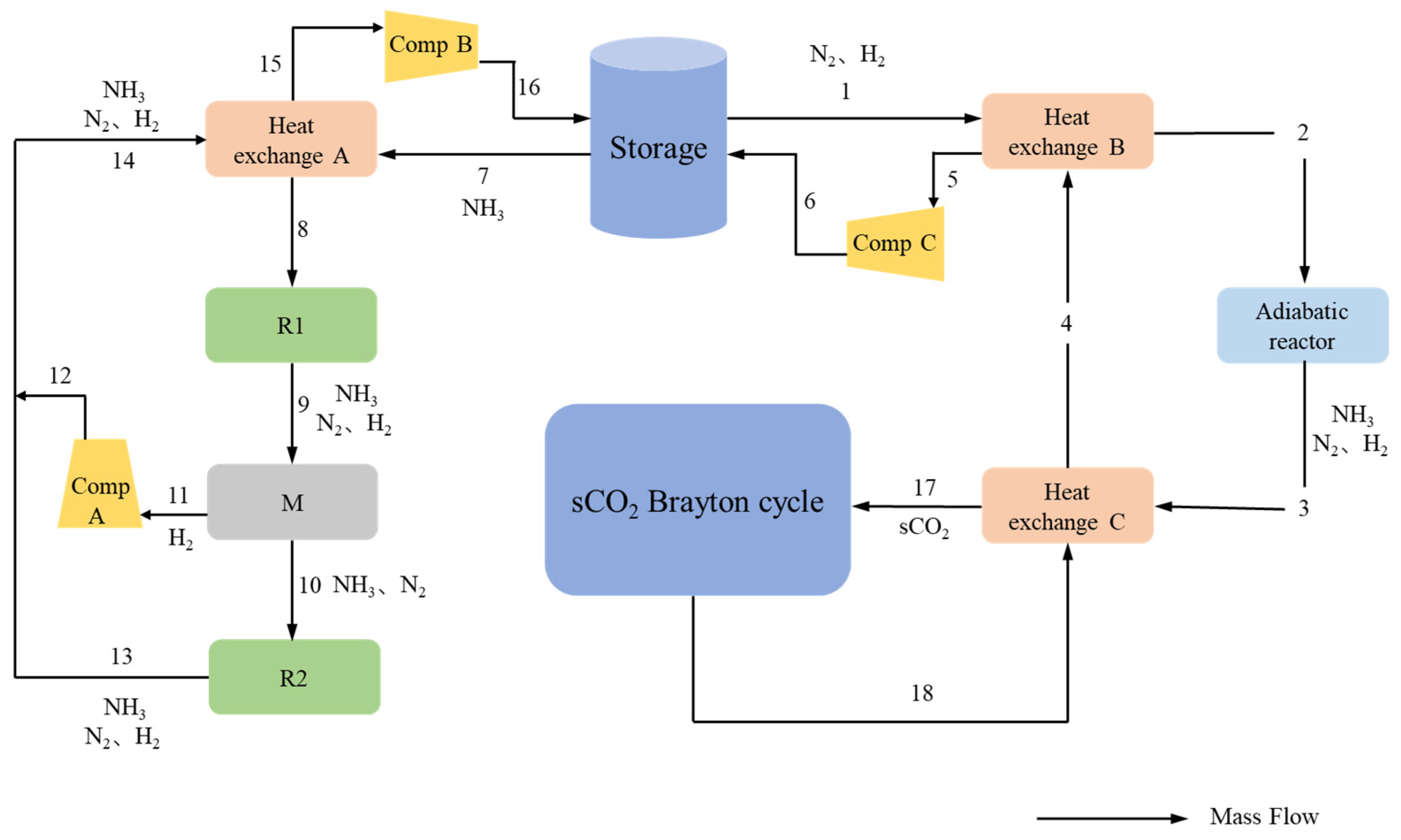
A system flowsheet of the ammonia-based solar TCES shown in Figure 3 is developed in the Aspen Plus software. In the flowsheet, the energy and exergy balances are computed for each component. As shown in Figure 3, the ammonia from the storage tank is preheated in the Heat exchanger B. Having been further preheated by the Heat exchanger A, ammonia is induced into the Endothermic reactor R1 for ammonia decomposition while absorbing solar energy during the daytime. Exiting from the Endothermic reactor R1, the gas mixtures of nitrogen, hydrogen, and ammonia pass through the Membrane M for hydrogen permeation. The remaining ammonia and nitrogen flow through the Endothermic reactor R2 for further decomposition. Thereafter, the gas mixtures form Membrane M and Endothermic reactor R2 flow back into the Heat exchanger A for heat recuperation. With the pressure compensated by the compressors (Compressors A and B), the gas mixture, eventually, flows back to the storage tank at the ambient temperature. For the discharging step, the nitrogen and hydrogen gas mixture (N2 + 3H2) from the storage tank firstly enters the Heat exchanger C for preheating. After the preheating process, the gas mixture enters the Adiabatic reactor for the ammonia synthesis reaction. Exiting from the Adiabatic reactor, the gas mixture is at an elevated temperature due to the exothermic character of the ammonia synthesis reaction. The hot gas mixture enters the Heat exchanger C to heat the supercritical CO2 to drive the sCO2 Brayton cycle. In the discharging loop, Compressor C is used to cover the pressure drop through the catalyst bed and the pipelines.
In the thermodynamic analysis, there are two assumptions:
  • The endothermic reactor is assumed to be a blackbody cavity-receiver with the effective absorptivity and emissivity to be 1;
  • The charging time is 8 h, considering a daytime of 8 h (clear sky) [38].
The mass balance is based on the fact that the ammonia dissociated in the charging loop is three times of the ammonia synthesized in the discharging loop:
mc,NH3 = 3 md,NH3
where mc,NH3 and md,NH3 (g/s) are the ammonia dissociated in the charging loop and the ammonia synthesized in the discharging loop, respectively.
For each endothermic reactor, the exergy balance is as follows:
Ein + EsErEe = Eout
where Ein (kW) is the exergy input from reaction flow, Es is the exergy input from the solar radiation, Er is the re-radiation exergy loss, Ee is the reaction exergy loss, and Eout is the exergy output of endothermic reactor. The exergy input from the solar radiation Er is computed as follows:
E s = Q s ( 1 T 0 T e )
where Qs (kW) is the solar radiation flux, T0 is the ambient temperature 298.15 K and Te (K) is the reaction temperature. In this study, the solar radiation concentrated by the heliostat is set to be 160 kW/m2 (a design point condition) corresponding to a concentration ratio of 160 (160 suns). The re-radiation exergy loss Er is calculated as follows:
E r = σ T e 4 ( 1 T 0 T e )
where Te is the endothermic reactor temperature, and σ (W/m2/K4) is the Stefan–Boltzmann constant.
In the model, the pressure drop through the catalytic bed is calculated with the following Ergun equation:
Δ p = 150 μ g L D p 2 ( 1 ε ) 2 ε 3 v g + 1.75 L ρ g D p ( 1 ε ) ε 3 v g 2
where Dp (m) is the equivalent diameter of catalyst particle, ε is the porosity of the catalyst bed. In the model, Dp is in the range 0.4 to 0.6 mm and ε is 0.764. The pumping power is provided by Compressor B and Compressor C, for each Compressor the exergy losses Ecomp is as follows:
E c o m p = m c ( e i n e o u t ) + W c o m p
where Wcomp (kW) is consumed power of Compressor, ein and eout (kW/kg) are the inlet and outlet unit mass exergy of compressor, respectively.
For the charging loop, the exergy loss of hydrogen permeation membrane is:
E p r e = m c ( e 9 e 10 e 11 )
For the Heat exchanger A, the exergy balance is as follows:
m c ( e 14 e 15 ) E h , A = m c ( e 8 e 7 )
The exergy loss Eh,A can be computed as follows:
E h , A = T 0 m c ( c p , c ln T 7 T 8 + c p , h ln T 14 T 15 )
where cp,c and cp,h (J/(kg⋅K)) are the mean specific heat capacities of the cold and hot flow in the Heat exchanger A, respectively. As the Flow 16 (N2, H2, and NH3) is not cooled to T0, the thermal energy for the Flow 16 between T16 and T0 is designed to be abandoned to the ambient temperature, which causes the following exergy loss Ecool,c:
E c o o l , c = m c ( e 16 e 16 , 0 )
where e16,0 is the specific exergy of Flow 16 at T0. Consequently, the relationship between mc,NH3 and the exergy losses in the charging loop is expressed as follows:
m c , N H 3 ( Δ H r T 0 Δ S r ) = E s E r E e E h , A E p r e E c o m p , A E c o m p , B E c o o l , c
where ΔHr (kW) and ΔSr (kW/T) are the heat and entropy of the ammonia decomposition reaction, respectively.
In the discharging loop, the exergy balance for adiabatic reactor is as follows:
m d e 2 E a = m d e 3
where md is the gas mass flow rate for the discharging loop. As there is no enthalpy change in the adiabatic reactor, the exergy loss of the adiabatic reactor Ea is only from the entropy changes of the reaction as follows:
E a = T 0 ( S 2 S 3 )
where S2 and S3 are the specific entropy of Flow 2 and Flow 3, respectively. For the Heat exchanger B, the exergy balance is the following:
m d ( e 4 e 5 ) E h , C = m s ( e 2 e 1 )
where ms is the sCO2 mass flow rate. The exergy loss Eh,B can be computed as follows:
E h , B = T 0 ( m s c p , c ln T 1 T 2 + m d c p , h ln T 4 T 5 )
The exergy balance for the Heat exchanger C is:
m d ( e 3 e 4 ) E h , C = m d ( e 17 e 18 )
The exergy loss Eh,C can be computed as follows:
E h , C = T 0 m d ( c p , c ln T 4 T 3 + c p , h ln T 18 T 17 )
Similar to Ecool,c, the exergy loss for the Flow 6 Ecool,d is calculated as follows:
E c o o l , d = m d ( e 6 e 6 , 0 )
where e5,0 is the specific exergy of Flow 5 at T0. As a result, the relationship between md,NH3 and the exergy losses of the discharging loop is expressed as follows:
m d , N H 3 ( Δ H r T 0 Δ S r ) = m s ( e 11 e 10 ) + E a + E h , B + E h , C + E c o m p , C + E c o o l , d
The overall solar-to-electricity efficiency of the system is as follows:
η s t e = ( W n e t W c o m p , D ) 24 W c o m p , C 8 Q s 8
where Wnet is the work output of power cycle and expressed as follows:
W n e t = λ ( H 15 H 16 )
where H15 and H16 are the specific enthalpy of Flow 15 and Flow 16, respectively, and λ is the power efficiency of recompress Brayton power cycle [39].
The hydrogen permeation flux equation expressed as follows [40]:
J H 2 = k ( P H 2 , i n 0.62 P H 2 , p e r 0.62 ) d m k = 3.21 × 10 8 exp ( 13140 8.314 × T g )
where JH2 is the hydrogen flux (mol H2/(m2s)), PH2,in and PH2,per (Pa) are the hydrogen partial pressure inside and permeation side of the membrane, dm (m) is the thickness of membrane, and Tg (K) is the gas temperature.

3. Model Validation

In this section, the model is validated by comparing the model generated ammonia mass fraction and reactor temperature with the established date from other references [40,41]. In the model, the Ni1.20/La0.32-Al2O3 catalyst [40] is designed to be used with the kinetic parameters listed in Table 1. Table 2 lists the inlet properties of reacting gas for ammonia decomposition and synthesis reactors.
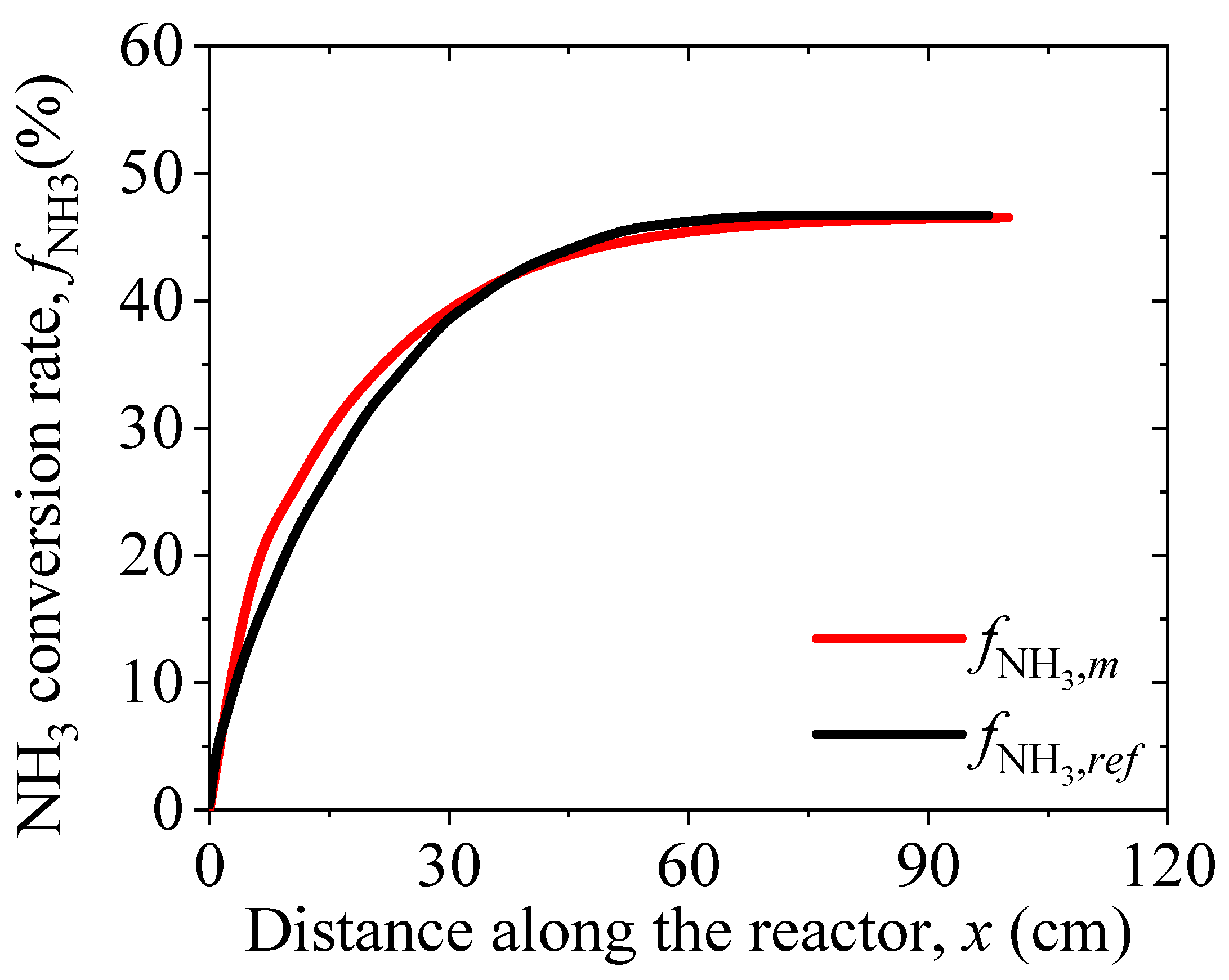
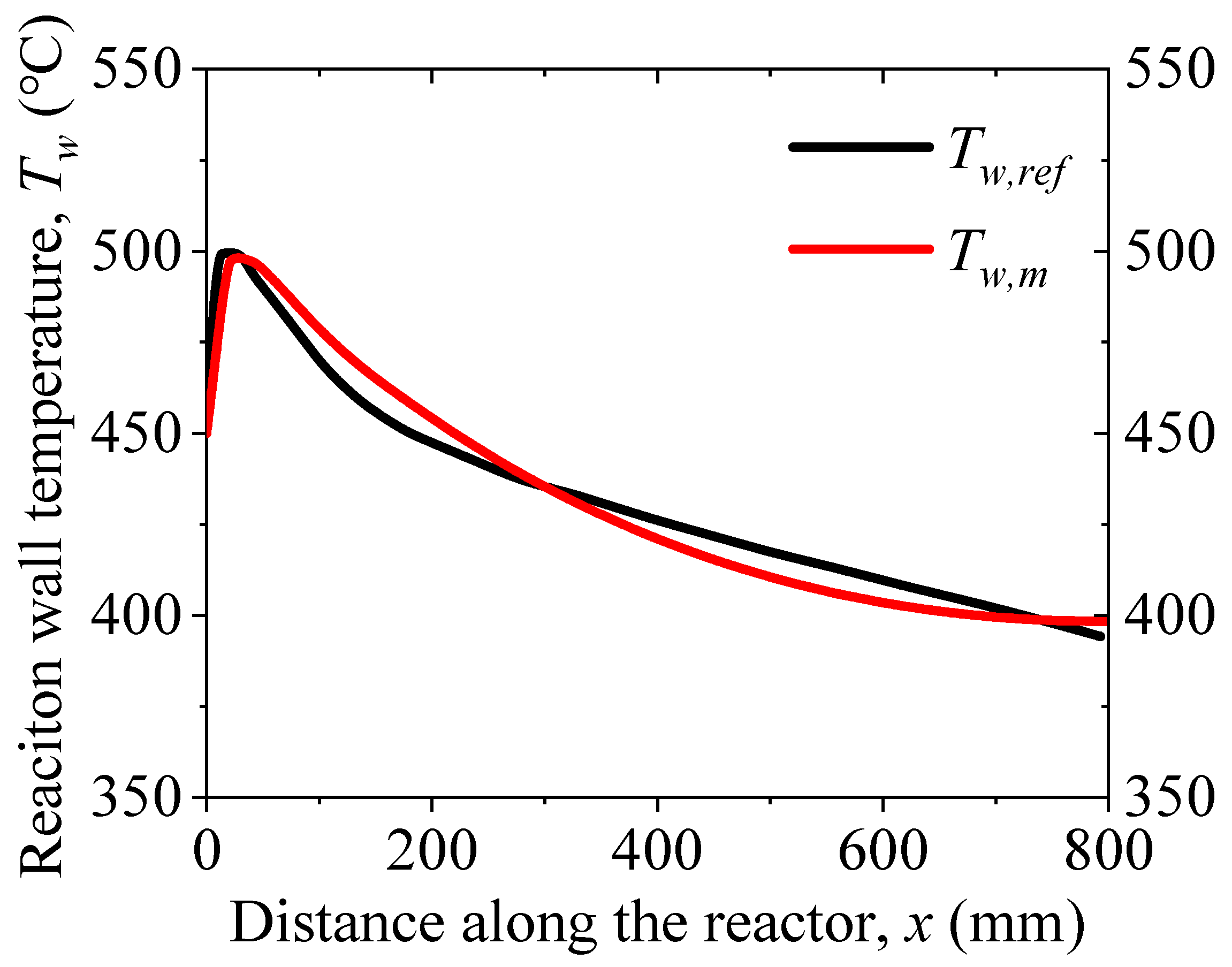
Figure 4 and Figure 5 show the comparison of our model-generated ammonia mass fraction and reactor wall temperature (fNH3,m and Tw,m) and the reference data (fNH3,ref and Tw,ref) [40,41], respectively. As shown in Figure 4 and Figure 5, the max relative error of Figure 4 and Figure 5 are 10.6% and 2.0%, respectively. Therefore, our model-generated results match with the established reference data. Consequently, the reactor model has been validated for both decomposition and synthesis reactors.

4. Results and Discussion

4.1. Thermodynamic Analysis of the Conventional System

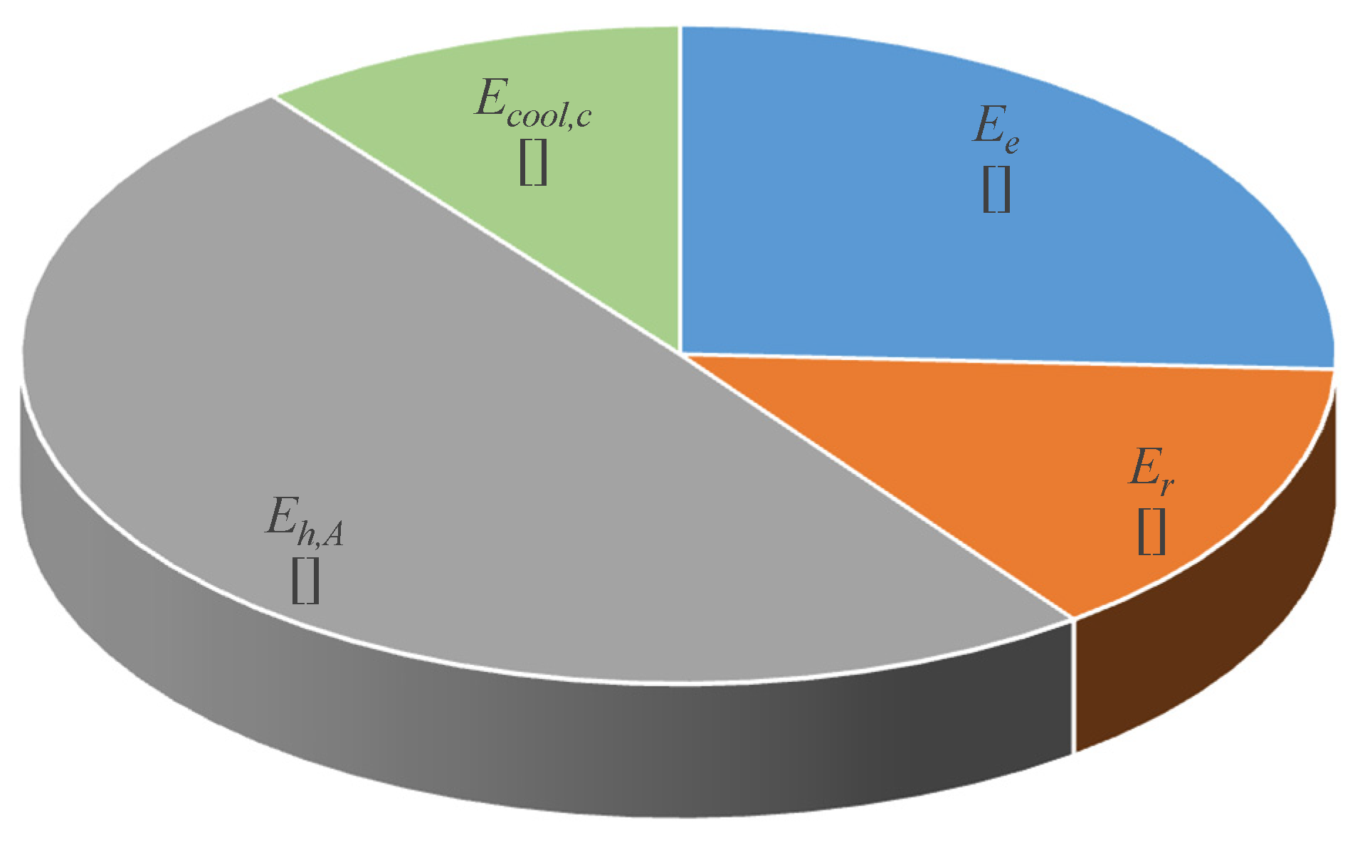
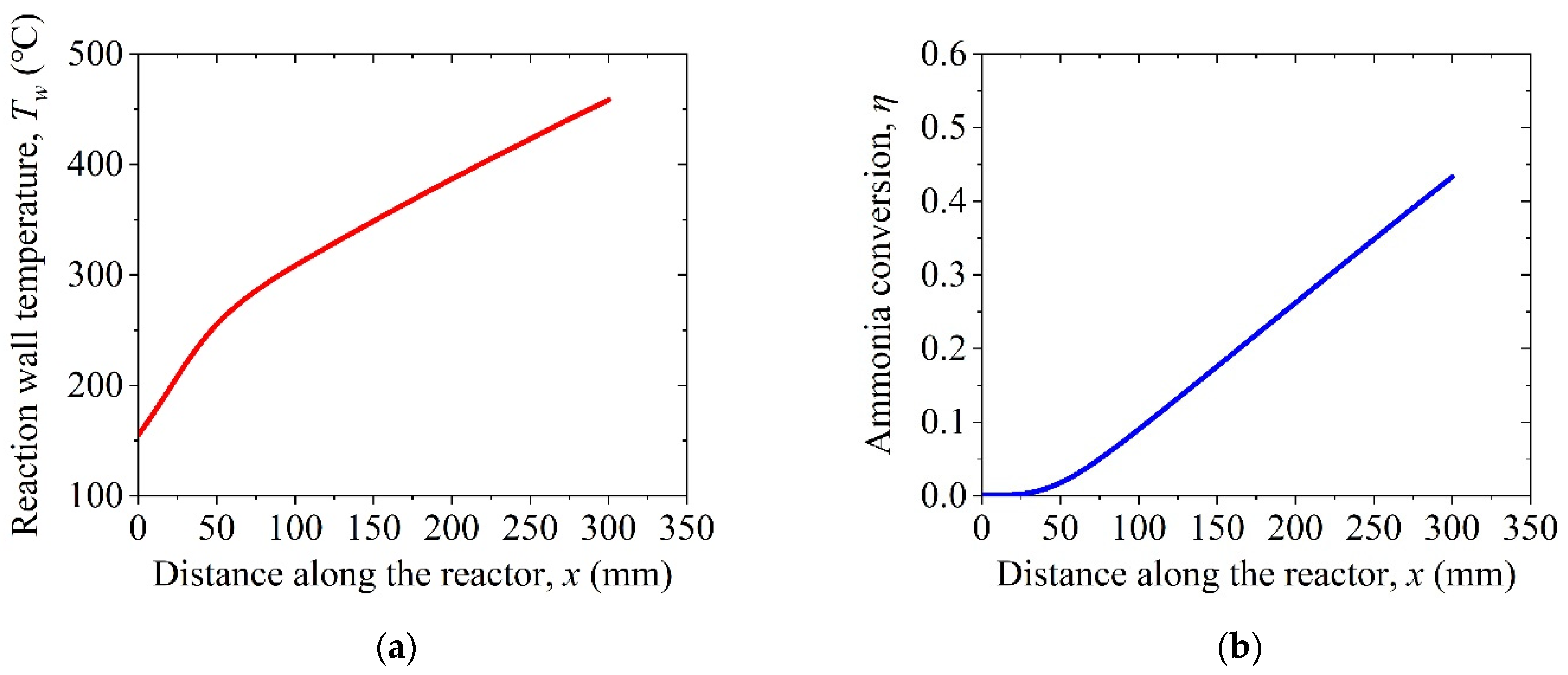
To begin with, the exergy losses of the conventional system without the hydrogen permeation membrane are analyzed in order to provide enough guidance on the efficiency improvement. Essentially, the conventional system can be simulated with the simplified model by removing an endothermic reactor, a membrane, and a compressor, while other components are not kept. Table 3 listed the properties of the system for the model input. Table 4 listed the model-generated exergy losses of the conventional system. As listed in Table 4, the exergy loss of the charging loop is much higher than that of the discharging loop. The solar-to-electricity efficiency ηste is only 19.3, even though the efficient recompress Brayton power cycle is incorporated. Figure 6 shows the exergy loss distribution of the charging loop, among which the exergy loss of Exchanger A Eh,A, the exergy loss due to re-radiation Er, and the exergy loss of the endothermic reaction Ee together are dominant. Since Ee determined by the reaction conversion is inevitable considering the capacity and scalability of the system, minimizing Er and Eh,A should be the key to improve the overall efficiency. Referring to Equations (4) and (6) above, Er and Eh,A depend on the temperature profiles of the ammonia decomposition reactor including the inlet and outlet temperatures. Figure 7 shows the temperature and the conversion profiles along the ammonia decomposition reactor. As shown in Figure 7a, the reacting gas temperature rises quickly near the inlet x < 50 mm. That is because the reaction rate shown in Figure 7b is low at such a low temperature, while more solar flux is transferred into the sensible heat. Having passed 300 °C, the increasing rate of reacting gas temperature in Figure 7a becomes smaller due to a faster reaction rate, inferred from the conversion profile in Figure 7b. Limited by the conversion, a large portion of the solar flux becomes the sensible heat rather than the reaction heat. Even though the high-temperature exiting gas mixture from the decomposition reaction is used to preheat the ammonia, there is still a large exergy loss through the heat recuperation process in the heat exchanger. In addition, the relatively high reaction temperature also causes large re-radiation loss. These facts explain why the Eh,A, together with Er, occupies 63% of the total exergy loss of the charging loop. Therefore, decreasing the reaction temperature as well as the temperature difference between the inlet and outlet of the reactor are anticipated to be the key in improving the efficiency.

4.2. Thermodynamic Analysis of the Proposed System

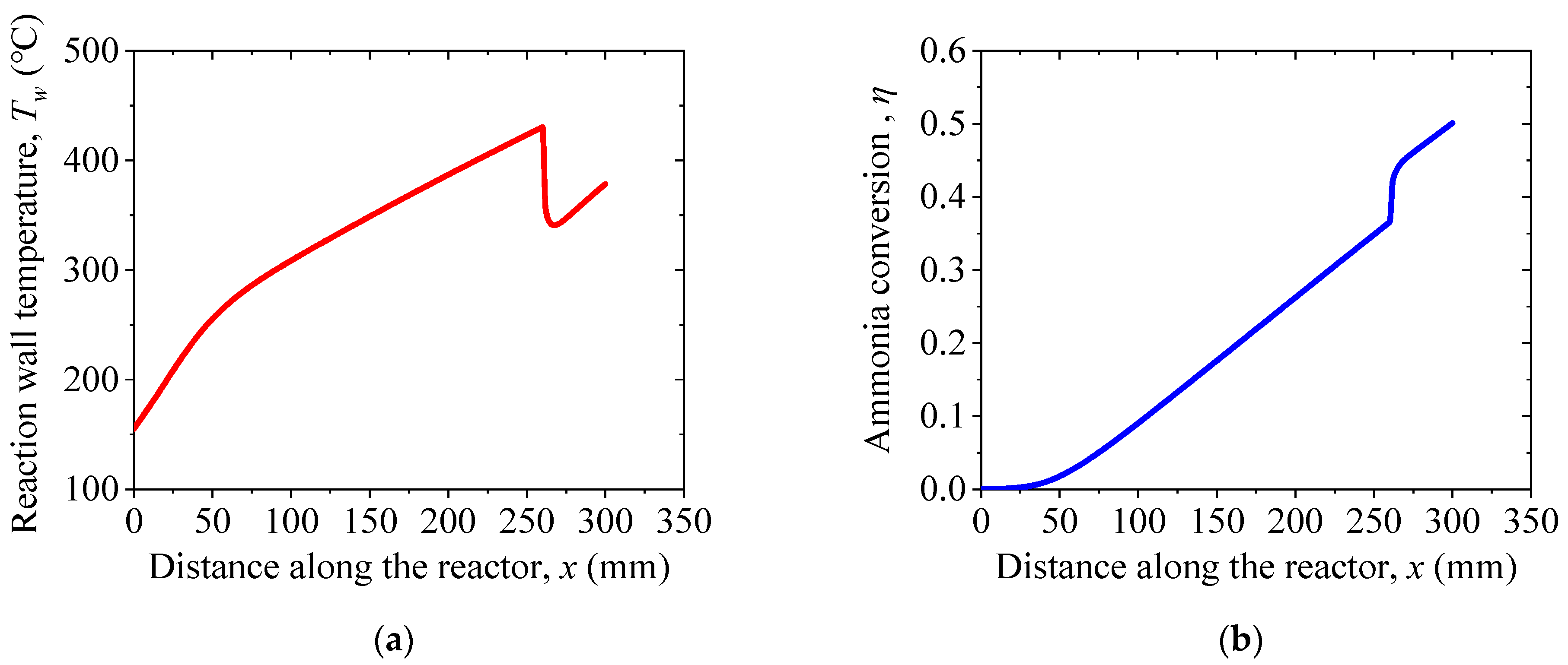
In this section, the proposed system with the hydrogen permeation membrane is studied. For a reasonable comparison, all the properties including the ammonia mass flow rate, endothermic reaction inlet temperature, catalyst bed length, and diameter, listed in Table 3, are fixed. Figure 8 shows the reaction temperature and conversion profiles of the ammonia decomposition reactor with the hydrogen permeation membrane. As shown in Figure 8, both the reaction temperature and ammonia conversion profiles are identical to those without the membrane in Figure 7 since the properties of the system for the model input are the same. Having passed the membrane at x = 260 mm, there is a dramatic decrease in the temperature and a rise in the conversion in Figure 8a,b, respectively, because of an extremely high reaction rate. Essentially, such a high reaction rate is caused by the combination effects of a high inlet temperature and ammonia mass fraction for the second reactor (R2). Compared with the system without the membrane, the proposed system achieves a higher conversion while the outlet temperature of the reacting gas become lower. As a result, Er and Eh,A are expected to be lower. Table 5 listed the exergy loss of the proposed system with the membrane. As listed in Table 5, Ee, compared with the conventional system, is higher because of a higher ammonia conversion. Meanwhile, Er, together with Eh,A, is more than 30% lower thanks to the membrane. On the other hand, there is a tiny increase exergy loss in the discharging loop because more ammonia is required to be synthesized in order to adapt to the higher conversion of the ammonia decomposition. Nonetheless, Wnet becomes larger with more ammonia synthesized. In all, the proposed system with the membrane has a higher solar-to-electric efficiency, 23.7%, which is 4.4% higher than the conventional system. As the maximum endothermic reaction temperature ~430 °C in Figure 8a can be realized with the parabolic-trough solar collectors, it is fair to investigate the thermodynamic feasibility of commercialization by comparing the solar-to-electric efficiency of the proposed system with that of a commercial parabolic trough solar power plant. Since the solar-to-electric efficiency of a typical parabolic trough solar power plant is 3.7% lower, i.e., the solar-to-electric efficiency of the Nevada Solar One solar power plant is 20% [42], the thermodynamic feasibility of commercialization is verified.

5. Conclusions

An ammonia-based solar thermochemical energy storage system implemented with a hydrogen permeation membrane is proposed for the first time. A system model including the ammonia decomposition coupled with the hydrogen permeation membrane, the ammonia synthesis reactor and the sCO2 Brayton cycle has been developed using the Aspen Plus software implemented with user-defined Fortran subroutines. The model has been validated by comparing our model-predicted temperatures and conversions profiles with established data from other references.
With the validated model, comprehensive thermodynamic analyses of the conventional system and the proposed system with the membrane have been performed. Moreover, the exergy distributions of systems are obtained to investigate the effects of the membrane on system efficiency improvement. The results show that exergy loss in the charging loop is dominant in the ammonia-based thermochemical energy storage system. Furthermore, the exergy losses of Heat Exchanger Eh,A, together with that of the re-radiation Er, play important roles in the exergy loss of the charging loop. For the proposed system, the hydrogen permeation membrane cannot only improve ammonia conversion but also reduce the endothermic reaction temperature, leading to a smaller temperature difference between the cold and hot flows in the preheating process. Compared with the conventional system, the Er and Eh,A of the proposed system are more than 30% lower. Consequently, the proposed system has a higher theoretical solar-to-electric efficiency of ηste = 23.7%, which are 4.4% and 5.7% higher than the conventional ammonia-based solar thermochemical energy storage system and the presented system, respectively [34]. Since the solar-to-electric efficiency of a typical parabolic trough solar power plant is 3.7% lower, the thermodynamic feasibility of commercialization for the ammonia-based solar thermochemical energy storage is verfied.

Author Contributions

Software, formal analysis, writing—original draft, Q.X.; methodology, writing—original draft, S.F. and M.K.; conceptualization, methodology, software, C.C. All authors have read and agreed to the published version of the manuscript.

Funding

This research was funded by Natural Science Foundation of Zhejiang Province, grant number No. LY20E060007; the National Natural Science Foundation of China, grant number No. 51806194; and the Basic Science Center Program for Ordered Energy Conversion of the National Natural Science Foundation of China, grant number No. 51888103. The authors gratefully acknowledge the support.

Institutional Review Board Statement

Not applicable.

Informed Consent Statement

Not applicable.

Data Availability Statement

All data are included in the paper or could be openly obtained.

Conflicts of Interest

The authors declare no conflict of interest.

References

  1. Peng, X.; Root, T.W.; Maravelias, C.T. Storing solar energy with chemistry: The role of thermochemical storage in concentrating solar power. Green Chem. 2017, 19, 2427–2438. [Google Scholar] [CrossRef]
  2. Van Vuuren, D.P.; Stehfest, E.; Gernaat, D.E.H.J.; Berg, M.V.D.; Bijl, D.L.; De Boer, H.S.; Daioglou, V.; Doelman, J.C.; Edelenbosch, O.Y.; Harmsen, M.; et al. Alternative pathways to the 1.5 °C target reduce the need for negative emission technologies. Nat. Clim. Chang. 2018, 8, 391–397. [Google Scholar] [CrossRef]
  3. Alamoudi, A.; Saaduddin, S.M.; Munir, A.B.; Muhammad-Sukki, F.; Abu-Bakar, S.H.; Yasin, S.H.M.; Karim, R.; Bani, N.A.; Mas’Ud, A.A.; Ardila-Rey, J.A.; et al. Using Static Concentrator Technology to Achieve Global Energy Goal. Sustainability 2019, 11, 3056. [Google Scholar] [CrossRef] [Green Version]
  4. Shao, J.; Chen, H.; Zhu, T. Solar Energy Block-Based Residential Construction for Rural Areas in the West of China. Sustainability 2016, 8, 362. [Google Scholar] [CrossRef]
  5. Bouaddi, S.; Fernández-García, A.; Sansom, C.; Sarasua, J.A.; Wolfertstetter, F.; Bouzekri, H.; Sutter, F.; Azpitarte, I. A Review of Conventional and Innovative- Sustainable Methods for Cleaning Reflectors in Concentrating Solar Power Plants. Sustainability 2018, 10, 3937. [Google Scholar] [CrossRef] [Green Version]
  6. Carrillo, A.J.; González-Aguilar, J.; Romero, M.; Coronado, J.M. Solar Energy on Demand: A Review on High Temperature Thermochemical Heat Storage Systems and Materials. Chem. Rev. 2019, 119, 4777–4816. [Google Scholar] [CrossRef]
  7. Zeng, Q.; Lai, Y.; Jiang, L.; Liu, F.; Hao, X.; Wang, L.; Green, M.A. Integrated Photorechargeable Energy Storage System: Next-Generation Power Source Driving the Future. Adv. Energy Mater. 2020, 10, 1903930. [Google Scholar] [CrossRef]
  8. Miguel, G.S.; Corona, B. Economic viability of concentrated solar power under different regulatory frameworks in Spain. Renew. Sustain. Energy Rev. 2018, 91, 205–218. [Google Scholar] [CrossRef]
  9. Fernández, A.G.; Gomez-Vidal, J.; Oró, E.; Kruizenga, A.; Solé, A.; Cabeza, L.F. Mainstreaming commercial CSP systems: A technology review. Renew. Energy 2019, 140, 152–176. [Google Scholar] [CrossRef]
  10. Du, K.; Calautit, J.; Wang, Z.; Wu, Y.; Liu, H. A review of the applications of phase change materials in cooling, heating and power generation in different temperature ranges. Appl. Energy 2018, 220, 242–273. [Google Scholar] [CrossRef]
  11. Prasad, J.S.; Muthukumar, P.; Desai, F.; Basu, D.N.; Rahman, M.M. A critical review of high-temperature reversible thermochemical energy storage systems. Appl. Energy 2019, 254, 113733. [Google Scholar] [CrossRef]
  12. Sarbu, I.; Sebarchievici, C. A Comprehensive Review of Thermal Energy Storage. Sustainability 2018, 10, 191. [Google Scholar] [CrossRef] [Green Version]
  13. Pardo, P.; Deydier, A.; Anxionnaz-Minvielle, Z.; Rougé, S.; Cabassud, M.; Cognet, P. A review on high temperature thermochemical heat energy storage. Renew. Sustain. Energy Rev. 2014, 32, 591–610. [Google Scholar] [CrossRef] [Green Version]
  14. Chen, X.; Zhang, Z.; Qi, C.; Ling, X.; Peng, H. State of the art on the high-temperature thermochemical energy storage systems. Energy Convers. Manag. 2018, 177, 792–815. [Google Scholar] [CrossRef]
  15. Humphries, T.D.; Møller, K.T.; Rickard, W.D.A.; Sofianos, M.V.; Liu, S.; Buckley, C.E.; Paskevicius, M. Dolomite: A low cost thermochemical energy storage material. J. Mater. Chem. A 2019, 7, 1206–1215. [Google Scholar] [CrossRef] [Green Version]
  16. Harries, D.N.; Paskevicius, M.; Sheppard, D.A.; Price, T.E.C.; Buckley, C. Concentrating Solar Thermal Heat Storage Using Metal Hydrides. Proc. IEEE 2012, 100, 539–549. [Google Scholar] [CrossRef]
  17. Wu, S.; Zhou, C.; Doroodchi, E.; Nellore, R.; Moghtaderi, B. A review on high-temperature thermochemical energy storage based on metal oxides redox cycle. Energy Convers. Manag. 2018, 168, 421–453. [Google Scholar] [CrossRef]
  18. Paskevicius, M.; Sheppard, D.; Williamson, K.; Buckley, C. Metal hydride thermal heat storage prototype for concentrating solar thermal power. Energy 2015, 88, 469–477. [Google Scholar] [CrossRef]
  19. Chaise, A.; De Rango, P.; Marty, P.; Fruchart, D.; Miraglia, S.; Olives, R.; Garrier, S. Enhancement of hydrogen sorption in magnesium hydride using expanded natural graphite. Int. J. Hydrogen Energy 2009, 34, 8589–8596. [Google Scholar] [CrossRef]
  20. Rönnebro, E.C.E.; Whyatt, G.; Powell, M.R.; Westman, M.P.; Zheng, F.; Fang, Z.Z. Metal Hydrides for High-Temperature Power Generation. Energies 2015, 8, 8406–8430. [Google Scholar] [CrossRef] [Green Version]
  21. Mejia, A.C.; Afflerbach, S.; Linder, M.; Schmidt, M. Experimental analysis of encapsulated CaO/Ca(OH)2 granules as thermochemical storage in a novel moving bed reactor. Appl. Therm. Eng. 2020, 169, 114961. [Google Scholar] [CrossRef]
  22. Mastronardo, E.; Bonaccorsi, L.; Kato, Y.; Piperopoulos, E.; Lanza, M.; Milone, C. Strategies for the enhancement of heat storage materials performances for MgO/H2O/Mg(OH)2 thermochemical storage system. Appl. Therm. Eng. 2017, 120, 626–634. [Google Scholar] [CrossRef]
  23. Li, Y.-T.; Li, M.-T.; Xu, Z.-B.; Meng, Z.-H.; Wu, Q.-P. Dehydration kinetics and thermodynamics of ZrO(NO3)2-doped Ca(OH)2 for chemical heat storage. Chem. Eng. J. 2020, 399, 125841. [Google Scholar] [CrossRef]
  24. Carrillo, A.J.; Sastre, D.; Serrano, D.P.; Pizarro, P.; Coronado, J.M. Revisiting the BaO2/BaO redox cycle for solar thermochemical energy storage. Phys. Chem. Chem. Phys. 2016, 18, 8039–8048. [Google Scholar] [CrossRef]
  25. Zhou, X.; Mahmood, M.; Chen, J.; Yang, T.; Xiao, G.; Ferrari, M.L. Validated model of thermochemical energy storage based on cobalt oxides. Appl. Therm. Eng. 2019, 159, 113965. [Google Scholar] [CrossRef]
  26. Albrecht, K.J.; Jackson, G.; Braun, R. Thermodynamically consistent modeling of redox-stable perovskite oxides for thermochemical energy conversion and storage. Appl. Energy 2016, 165, 285–296. [Google Scholar] [CrossRef] [Green Version]
  27. Dizaji, H.B.; Hosseini, H. A review of material screening in pure and mixed-metal oxide thermochemical energy storage (TCES) systems for concentrated solar power (CSP) applications. Renew. Sustain. Energy Rev. 2018, 98, 9–26. [Google Scholar] [CrossRef]
  28. Yuan, Q.; Ding, J.; Lu, J.; Yu, T.; Wang, W. Heat Transfer and Energy Storage Performance of Methane Reforming with Carbon Dioxide in Semi-cavity Reactor. Procedia Eng. 2016, 157, 365–373. [Google Scholar] [CrossRef] [Green Version]
  29. Fuqiang, W.; Jianyu, T.; Huijian, J.; Yu, L. Thermochemical performance analysis of solar driven CO2 methane reforming. Energy 2015, 91, 645–654. [Google Scholar] [CrossRef]
  30. Chen, C.; Liu, Y.; Aryafar, H.; Wen, T.; Lavine, A.S. Performance of conical ammonia dissociation reactors for solar thermochemical energy storage. Appl. Energy 2019, 255, 113785. [Google Scholar] [CrossRef]
  31. Lovegrove, K.; Luzzi, A.; Soldiani, I.; Kreetz, H. Developing ammonia based thermochemical energy storage for dish power plants. Sol. Energy 2004, 76, 331–337. [Google Scholar] [CrossRef]
  32. Chen, C.; Aryafar, H.; Warrier, G.; Lovegrove, K.M.; LaVine, A.S. Ammonia synthesis for producing supercritical steam in the context of solar thermochemical energy storage. AIP Conf. Proc. 2016, 1734, 050010. [Google Scholar]
  33. Chen, C.; Lovegrove, K.M.; Sepulveda, A.; Lavine, A.S. Design and optimization of an ammonia synthesis system for ammonia-based solar thermochemical energy storage. Sol. Energy 2018, 159, 992–1002. [Google Scholar] [CrossRef]
  34. Luzzi, A.; Lovegrove, K.; Filippi, E.; Fricker, H.; Schmitz-Goeb, M.; Chandapillai, M.; Kaneff, S. Techno-Economic Analysis of a 10 MWe Solar Thermal Power Plant Using Ammonia-Based Thermochemical Energy Storage. Sol. Energy 1999, 66, 91–101. [Google Scholar] [CrossRef]
  35. Lu, J.; Chen, Y.; Ding, J.; Wang, W. High Temperature Energy Storage Performances of Methane Reforming with Carbon Dioxide in Tubular Packed Reactor. Energy Procedia 2014, 61, 407–410. [Google Scholar] [CrossRef] [Green Version]
  36. Basile, A.; Gallucci, F.; Paturzo, L. Hydrogen production from methanol by oxidative steam reforming carried out in a membrane reactor. Catal. Today 2005, 104, 251–259. [Google Scholar] [CrossRef]
  37. Ardaneh, M.; Abolhasani, M.; Esmaeili, M. CFD modeling of two-stage H2 recovery process from ammonia purge stream by industrial hollow fiber membrane modules. Int. J. Hydrogen Energy 2019, 44, 4851–4867. [Google Scholar] [CrossRef]
  38. Chacartegui, R.; Alovisio, A.; Ortiz, C.; Valverde, J.M.; Verda, V.; Becerra, J. Thermochemical energy storage of concentrated solar power by integration of the calcium looping process and a CO2 power cycle. Appl. Energy 2016, 173, 589–605. [Google Scholar] [CrossRef]
  39. Chen, C.; Xia, Q.; Feng, S.; Liu, Q. A novel solar hydrogen production system integrating high temperature electrolysis with ammonia based thermochemical energy storage. Energy Convers. Manag. 2021, 237, 114143. [Google Scholar] [CrossRef]
  40. Wang, B.; Kong, H.; Wang, H.; Wang, Y.; Hu, X. Kinetic and thermodynamic analyses of mid/low-temperature ammonia decomposition in solar-driven hydrogen permeation membrane reactor. Int. J. Hydrogen Energy 2019, 44, 26874–26887. [Google Scholar] [CrossRef]
  41. Kreetz, H.; Lovegrove, K. Exergy analysis of an ammonia synthesis reactor in a solar thermochemical power system. Sol. Energy 2002, 73, 187–194. [Google Scholar] [CrossRef]
  42. Jones, J. Concentrating solar power, CSP lifts off 2007. Renew Energy World 2007, 10, 36–38. [Google Scholar]
Figure 1. A schematic of a typical ammonia-based solar thermochemical energy storage system.
Sustainability 13 12783 g001
Figure 2. Schematics of ammonia decomposition reactor coupled with a hydrogen permeation membrane.
Sustainability 13 12783 g002
Figure 3. Flowsheet of the ammonia-based solar TCES (the numbers in the figure representing the each mass flow of the proposed system).
Sustainability 13 12783 g003
Figure 4. Comparison of our model predicted (fNH3,m) and experimentally measured (fNH3,ref) [40] ammonia mass fraction of ammonia decomposition reactor.
Sustainability 13 12783 g004
Figure 5. Comparison of our model predicted (Tw,m) and experimentally measured (Tw,ref) [41] reactor wall temperature of ammonia synthesis reactor.
Sustainability 13 12783 g005
Figure 6. Exergy loss distribution of the charging loop.
Sustainability 13 12783 g006
Figure 7. (a) Reaction temperature and (b) ammonia conversion rate of conventional system along the reactor endothermic.
Sustainability 13 12783 g007
Figure 8. (a) Reaction temperature and (b) ammonia conversion rate of system with membrane along the endothermic reactor.
Sustainability 13 12783 g008
Table 1. The reaction rate parameters used in the model.
Activation Energy, Ea
J/mol
Pre-Exponential Constant, ko,m
kmol/m3∙s
4.57 × 1052.645 × 1011
Table 2. The properties of ammonia decomposition/synthesis reactors for model validation.
ParametersDecomposition ReactorSynthesis Reactor
Reactor length, mm110800
Reactor outer diameter, cm1-
Reactor inner diameter, cm0.950.15
Mass flow rate, g/s0.00750.10
Reactor wall temperature, °C150-
Reactor inlet temperature, °C-450
Table 3. Input properties of model.
Ammonia Mass Flow Rate, mc (g/s)Catalyst Bed Length, L (mm)Catalyst Bed Diameter, D (mm)
1.830030
Table 4. Exergy loss distribution of system without membrane.
ItemsExergy Loss, E (kW)
Charging loop
Endothermic reaction exergy loss, Ee0.2587
Re-radiation exergy loss, Er0.1419
Heat exchanger A exergy loss, Eh,A0.4980
Compressor B exergy loss, Ecomp,B<1%
Charging loop cooling exergy loss, Ecool,c0.1068
Total of the Charging loop1.0055
Discharging loop
Adiabatic reaction exergy loss, Ea0.1612
Heat exchanger B exergy loss, Eh,B0.1403
Heat exchanger C exergy loss, Eh,C0.0519
Compressor C exergy loss, Ecomp,C<1%
Discharging loop cooling exergy loss, Ecool,d0.0002
Total of the discharging loop0.3537
Overall system exergy loss1.3592
Wnet0.8751
ηste19.3%
Table 5. Charging loop exergy loss of system 2.
ItemsExergy Loss, E (kW)
Charging loop
Endothermic reaction exergy loss, Ee0.2801
Re-radiation exergy loss, Er0.1172
Heat exchanger A exergy loss, Eh,A0.3290
Compressor A exergy loss, Ecomp,A<1%
Pressure exergy loss, Epre0.0080
Compressor B exergy loss, Ecomp,B<1%
Charging loop cooling exergy loss, Ecool,c0.0376
Total of the Charging loop0.7727
Discharging loop
Adiabatic reaction exergy loss, Ea0.2017
Heat exchanger B exergy loss, Eh,B0.1755
Heat exchanger C exergy loss, Eh,C0.0650
Compressor C exergy loss, Ecomp,C<1%
Discharging loop cooling exergy loss, Ecool,d0.0003
Total of the discharging loop0.4426
Overall system exergy loss1.1777
Wnet1.0737
ηste23.7%
Publisher’s Note: MDPI stays neutral with regard to jurisdictional claims in published maps and institutional affiliations.