Abstract
To improve the flexural behavior of thin bonded cement-based overlays, this study was carried out on the use of repair material incorporating amorphous metallic fibers (AMFs) in combination with the rubber aggregates obtained from grinding of worn-out tires. For this study, sixteen mortar mix compositions were prepared to contain AMFs and/or rubber aggregates to be used as overlay material while the substrate used was plain cement mortar. Rubber aggregates were incorporated at three different replacement ratios (i.e., 10%, 20% and 30%) by an equivalent volume of sand, and AMFs were added in three different dosages (i.e., 10 kg/m3, 20 kg/m3 and 30 kg/m3). In this study, composite beams (500 × 100 × 140 mm) comprising substrate (500 × 100 × 100 mm) and repair layer (500 × 100 × 40 mm) were prepared and investigated under flexural loading. Experimental results showed that the increase in rubber content resulted in a decrease compressive strength, flexural strength and modulus of elasticity. Rubberized fiber-reinforced cementitious composites (30R30F) exhibited higher flexural toughness and the flexural toughness improved up to 400%. Toughness and maximum deflection of composite beams enhanced significantly due to synergetic effect of AMF and rubber aggregates. It was observed that before peak load, rubber plays its role by delaying the micro-crack propagation. Results also revealed that the steel fibers reinforcement plays an important role in restraining the crack openings under flexure loading. In the post-peak region, steel fibers control the cracks from propagating further by bridging action and provide higher post-peak residual strength.
1. Introduction
Construction industry has been utilizing concrete material since long time. After years in service, it is common for concrete structures to deteriorate over time. For concrete or reinforced concrete structures, time affects their state in many ways depending upon their geometries, exposure and applied loading. It is also a well-known fact about concrete that ultimate load capacity of existing concrete structures degrades with the passage of time. This is mainly caused due to applied loading, corrosion, weathering, chemical attack, shrinkage, etc. [1]. To solve this problem, rehabilitation and repairing of structures are required which enhance the serviceability limit of concrete structure.
Rehabilitation of concrete can be carried out using different methodologies. A cement-based thin bonded overlay is one of the techniques which is used for the rehabilitation of concrete structures. Among different rehabilitation techniques, this technique is one the most efficient and economical rehabilitation technique for structures with greater surface areas [2]. This repair technique is used for slab on grade, pavements, bridge decks and walls as well. The durability of a thin bonded overlay is compromised when cracks are developed in the new repair layer. This cracking, regardless of its origin, is among primary reason for jeopardizing the durability of repaired structures since these cracks propagate to the interface of the new repair layer and substrate which initiates debonding of the new layer [3,4,5]. Debonding mechanism is initiated as a result of two main causes (i.e., applied mechanical loading and restrained shrinkage deformation between overlay and substrate) [2,4].
According to previous research, chances of cracking can be reduced if a repair material with high tensile strength is used [6,7]. Moreover, the strain capacity of repair material is also increased with a repair material having a low modulus of elasticity. This helps in delaying cracking which results from restrained shrinkage between substrate and overlay [7]. Unfortunately, such material with low modulus and high tensile strength does not exist ideally. Research shows that if metallic fibers are incorporated in overlays, it improves the ductility of mortar by delaying initiation and propagation of debonding of overlay from the substrate [8,9,10]. Further, the use of rubber aggregates improves deformation capacity prior to macro-cracking localization, and it is further enhanced by metallic fiber [5]. The mechanical performance of concrete was also evaluated using rubber aggregates only and rubber aggregates along with hooked end steel fibers [11]. Hook ended steel fibers were added with ratio of 0.5% by volume fraction while rubber aggregates was used in different percentages as a replacement of sand. In both rubberized and/or fiber-reinforced concrete, there was a considerable reduction in density, compressive strength and elastic modulus of concrete. This reduction was observed with the increment of rubber content. Similarly, a decrease in split tensile and flexural strength was also observed with the increase in percentage content of rubber aggregates in rubberized and steel fiber-reinforced rubberized concrete. Simultaneously, strain capacity enhanced with the increased dosage of rubber aggregates in both rubberized and steel fiber-reinforced rubberized concrete [11].
To enhance the toughness and flexural strength of concrete, amorphous metallic fibers (AMF) were used in concrete and combined with hooked-ended steel fibers (SF) which showed that the flexural strength of concrete is significantly increased with the addition of AMF and the synergetic effect between AMF and SF also enhanced the performance of concrete. Due to the synergetic effect of hybrid mixes, the flexural toughness was much better than that of a single type of fibers. Moreover, amorphous metallic fibers have high corrosion resistance [12].
A detailed investigation was conducted on rubberized lightweight aggregate concrete by Miller et al. in 2017 [13] and the results suggested that the ductility and toughness of concrete are enhanced [13]. Experimental field validation was also carried out to implement laboratory findings (i.e., the use of rubber aggregates reduces cracking) [14]. It was concluded that a large area of concrete can be constructed without providing joints with the usage of rubber obtained from end-of-life tires since the joints are the main source of damage initiation in pavements which leads to costly maintenance and rehabilitation works. Furthermore, recycling waste products is one of the most effective methods for reducing environmental pollution. Also, disposing of used tyres in landfills directly can result in a variety of environmental and economic problems [15,16]. Many researchers suggested using crumb rubber aggregates obtained from end-of-life tyres to make sustainable concrete as a way to dispose of the waste tyres which in turn promotes the circular economy also [17,18,19]. Aside from the environmental benefits, using scrap rubber as a crumb rubber in concrete mixes is thought to improve toughness [20], impact resistance [21], fatigue [22,23], thermal insulation [24], and other concrete properties. Also, utilizing energy efficient materials in walls has been reported for heat transport and heat flow [24,25,26,27].
Fracture characteristics of plain concrete and steel fiber reinforced concrete were studied by Noaman et al. [28] who showed that with the increment of rubber content, compressive strength, tensile strength, and flexural strength reduced. Moreover, the flexural behavior of large-scale beams was also investigated by adding crumb rubber with and without steel fibers. Twelve beams were cast and tested with a cross-sectional area of 250 × 250 mm and a length of 2440 mm. It helped to increase the ductility, toughness and flexural capacity of the beam and further reduced the self-weight of the beam [29]. The strain capacity of concrete is enhanced even though the modulus of elasticity and material strength is reduced by a positive synergetic effect between steel fiber reinforcement and rubber aggregates. The high strain capacity of rubber aggregates and residual post-peak strength of fiber reinforcement can be used to control cracking [5]. Gillani et al. [30] investigated the mechanical properties as well as the fracture energy of rubberized fiber-reinforced mortars. Although, mechanical properties showed reduction by the incorporation of rubber aggregates in mortar mixes. However, fracture energy increased significantly in rubberized fiber-reinforced mortar mixtures especially in case of 30% rubber and 30 kg/m3 of fiber reinforcement. Centonze et al. [31] performed tests on beams and slabs by incorporating waste tires steel fibers under flexural loading to evaluate cracking in the post-peak region. Brittle behavior was reduced which means more energy is absorbed and toughness is increased. Khan et al. [32] studied the effectiveness of hybrid steel-basalt fiber reinforced concrete under compression and mechanical characteristics and microcosmic mechanism of basalt fiber modified rubber composites were investigated by Bu et al. [33]. Experimental investigations have been conducted by Noaman et al. [20] on compression toughness, Noaman et al. [34] on impact energy and Bakar et al. [35] on flexural toughness of rubberized steel fiber concrete. Results showed that the brittle behavior of concrete changes to ductile behavior by incorporating rubber and steel fibers in concrete. Compression and flexural toughness also increased by an increase in crumb content. Impact energy is also improved by the combination of steel fibers and rubber aggregates both at the initial crack and ultimate failure.
For using bonded overlay technique for the rehabilitation of large surface areas, surface preparation plays a vital role in interfacial bond strength development of a new repair layer of concrete with the substrate which in return affects the durability of concrete [36,37,38,39,40]. Rubber aggregates and fiber reinforcement were incorporated in thin bonded cement-based overlays and their effect was studied on durability [9,10,41,42]. Results showed improvement in strain capacity of overlays with increment in rubber content, but tensile strength was reduced. Residual post-peak strength also improved significantly with the addition of metallic fibers. Further, it was concluded that crack opening and debonding can be controlled by using rubber aggregates and steel fibers as it enhances strain capacity and residual post-peak strength [22]. Tran et al. [7] and Toumi et al. [43] focused on key parameters influencing the propagation of debonding along the interface of the substrate and overlay under static and fatigue loading. It was observed that steel fibers had the capacity to control debonding by restraining the opening of cracks. Debonding initiation and its propagation along overlay- substrate interface of thin bonded cement-based material under bending loading were studied by Gillani et al. [44]. They found that strain capacity improved for the composite beams repaired with the material incorporating both rubber aggregates and metallic fibers. Digital image correlation technique was used to monitor the cracking propagation and to measure the debonding length along the interface. Numerical Modelling of repaired beam was also carried out to study its structural behavior and compared with the experimental results which were found to be in coherence. Moreover, the interface debonding is more obvious in repair beams without fibers, and it was well-controlled in repairs using both rubber aggregates and fibers. It also demonstrates the synergetic effect of using rubber particles and fibers together.
In the light of previous research, it can be argued that characteristics of repair material and bond between overlay and substrate are the controlling parameters for the durability of repair system. The durability is jeopardized if cracking of the repair layer occurs. Hence, the combined use of steel fibers and rubber aggregates for the production of repair material can be a viable option to improve the durability characteristics of overlays leading to development of a sustainable repair material. Moreover, the use of recycled material in concrete is still on the lower side due to a lack of awareness and research on the properties of recycled materials. The new emerging technique used for the rehabilitation of concrete is a thin bonded cement-based overlay, and this research will be helpful to introduce this novel and innovative technique. In addition, the use of waste rubber obtained from used tires in repair material will open a new field of research. It will also be helpful in protecting the environment and in the friendly disposal of solid waste.
2. Materials
For the substrate layer, mortar constituted of ordinary Portland cement, fine aggregates, and superplasticizer and for the repair layer, mortar constituted of rubber and steel fibers, in addition to ordinary Portland cement and fine aggregates. The fine aggregates used in mortar were obtained from Lawrencepur quarry, Pakistan (Figure 1). The grain size of sand was in the range of 0–4 mm. For gradation of the sand, standard sieve shaker was used in which stack of sieves were placed and shaking was carried out for 10 to 15 min. After shaking, the mass retained on each sieve was measured to calculate the fineness modulus of sand. Specific gravity of sand was measured by using pycnometer of capacity 50 mL. The specific gravity and fineness modulus of Lawrencepur sand were 2.73 and 2.82, respectively. The grading curve of Lawrencepur sand is provided in Figure 2. A third-generation superplasticizer (i.e., Sika ViscoCrete 3110 was used in the mortar for the required workability and for avoiding the segregation of rubber aggregates). The addition of fibers in the cement mix induces a reduction in its workability whereas lighter aggregates (i.e., rubber aggregates cause segregation in the cement mix). Since, the specific gravity of rubber aggregates used in this study is 1.2 which is lesser than that of sand (i.e., 2.73). To tackle these problems, a third-generation superplasticizer (i.e., Sika ViscoCrete 3110 was used in the mortar for the required workability and to avoiding the segregation of rubber aggregates). This superplasticizer also includes properties of viscosity modifying agent. The slump was maintained by adjusting the dosage of superplasticizer in all mix compositions, including the control mortar, to consider the effect of admixture on the behavior of materials.
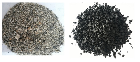
Figure 1.
Sand and rubber aggregates.
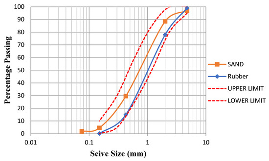
Figure 2.
Grading curve of sand and rubber aggregates along with ASTM limits.
Amorphous metallic fibers were used in the mortar for repair overlays. Research had shown that material having high tensile strength reduced the risk of cracking and delays the crack initiation and propagation [7,22]. Amorphous metallic fibers are very flexible, straight, and easy to handle. In addition to that, these fibers are corrosion-resistant [12]. The image of metallic fibers used is shown in Figure 3. The amorphous metallic fibers used are FF30L6 FibraFlex provided by Saint Gobain Seva. The characteristics of Amorphous metallic fibers and other types of fibers used by previous researchers are presented in Table 1. Rubber aggregates were made by grinding end-of-life tires. The sand was partially replaced by rubber aggregates by equivalent volume in different percentages. Literature on rubber aggregates has also shown that the use of rubber aggregates improved strain capacity before macro-cracking [5]. The specific gravity of rubber aggregates used is 1.2 whereas the specific gravity of sand is 2.73. The rubber aggregates used in this study are shown in Figure 1. The maximum size of rubber aggregates used does not exceed 4 mm which is comparable to the size of sand particles. The particle size distribution curve of rubber aggregates was obtained by sieve analysis performed in accordance with ASTM C33 and presented in Figure 2. To enhance the durability of thin bonded overlays, the work approach adopted in this research is presented in a flow chart shown in Figure 4.
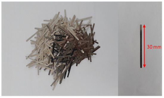
Figure 3.
Amorphous metallic fibers of 30 mm length.

Table 1.
Characteristics of amorphous metallic fibers (Saint Gobain Seva).
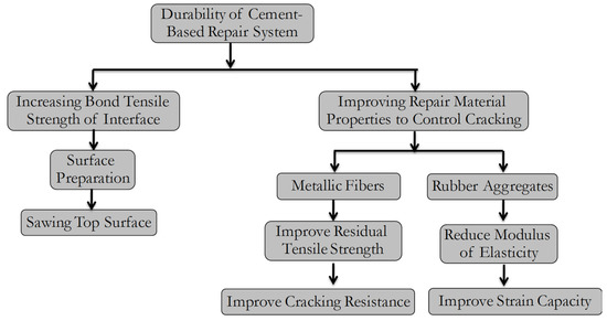
Figure 4.
Flow chart showing the work approach adopted to enhance the durability of cement-based repairs.
3. Mixture Compositions
Keeping in view the previous study [5], the maximum dosage of rubber aggregates and steel fibers was kept limited. Three different dosages of rubber aggregates were used (i.e., 10%, 20%, and 30% as partial replacement of natural aggregates by volume). Similarly, three different dosages of steel fibers were used in this research (i.e., 10 kg/m3, 20 kg/m3, and 30 kg/m3). A total of sixteen mortar mixtures were prepared and tested for three dosages of rubber aggregates in combination with three contents of steel fibers and one control mortar. Slump value was maintained between the range of 1 inch to 1.5 inches for all mixture compositions. The mix design composition of all mortar mixes is shown in Table 2.
Table 2.
Mixture design composition (kg/m3).
A simple nomenclature was adopted to designate mixture compositions. The letters R (Rubber) and F (Fibers) are preceded by numbers that represent the proportions of rubber aggregates and steel fibers, respectively. For example, 10R20F designates the mortar containing 10% of the rubber aggregates and reinforced with 20 kg/m3 of fibers.
4. Testing Methods
4.1. Mechanical Tests
Compressive strength tests were conducted after 28 days on cylindrical. specimens having dimensions of 100 mm diameter. and 200 mm height. The compression tests were performed.in accordance with ASTM C39. For each mix, three samples were tested. The test setup for the compression test is shown in Figure 5. Modulus of Elasticity (MOE) tests. were. conducted after 28 days on cylindrical. specimens having dimensions of 100 mm diameter. and 200 mm height. The tests were conducted. according. to ASTM C469. The test setup for the MOE test is shown in Figure 5. Two LVDTs were attached to the specimen to measure deformations which were used to calculate strain.
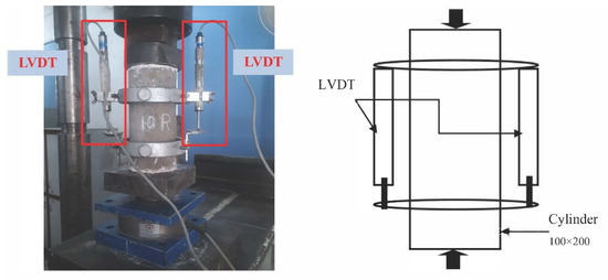
Figure 5.
Actual test setup and its schematic representation for compression and MOE test.
4.2. Three-Point Static Bending Test on Composite Beams
The composite specimens consisted of a thin repair layer on top of the substrate simulating repaired beam. Cementitious substrates without rubber aggregates and fiber-reinforcement 0R0F were prepared to have the real application. Prism beams were cast in two phases. In the first phase, the substrate layer was cast which simulated the structure to be repaired. The size of the substrate layer was 100 × 100 × 500 mm. After the substrate layer had been water cured for 28 days, the top surface of the prism was prepared for the casting of the repair overlay. Surface preparation must provide good anchorage to the new layer. Different techniques are available for the preparation of mortar surface to give better bonding. The technique used to prepare and level the surface of the substrate was sawing the top 5 mm layer. In the second phase, a cement-based overlay was cast over the substrate after the preparation of the surface. Mold was modified and arranged to cast a 40 mm repair layer over a 100 mm substrate with a 10mm notch at the center. Sixteen different repair layers were cast over the substrate according to the design mix presented in Table 2. Cast composite prisms were then water cured for 28 days at controlled temperature of 20 °C and relative humidity of 98%. Then the cleaned surface was white washed for clear visibility of cracks during testing.
Three-point static bending test was carried out on Shimadzu Universal Testing Machine having a loading capacity of 1000 KN to study the behavior of the overlay–substrate under flexure. A schematic diagram of the repaired composite prism under three-point static bending test and the complete actual testing setup are shown in Figure 6. This test was conducted according to the RILEM TC 162-TDF [47]. These tests were conducted at a loading rate of 0.5 mm/min. Two LVDTs were attached with the composite prism to measure the mid-span deflection and the crack mouth opening (CMOD). CMOD was measured by the LVDT attached at the notch location in the mid span and the vertical deflection of the composite specimens was monitor by other LVDT sensor at the support location.
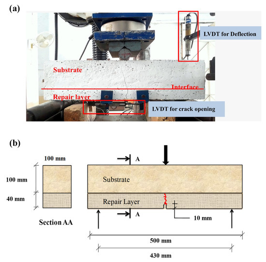
Figure 6.
(a) Actual test setup for three-point bending test; (b) schematic diagram.
Under flexural loading, the crack was initiated from the tip of the notch in the overlay, which eventually travels towards the interface. The values of force, deflection, and crack mouth opening displacement (CMOD) were automatically recorded. by the data. acquisition. system. of Shimadzu Universal Testing Machine.
5. Results and Discussions
For material characterization, a minimum of three specimens were tested, and the results presented for each composition are the average of these tests.
5.1. Compressive Strength
Compressive strength results of all mortar mixtures are presented in Figure 7. The average of three specimens is shown in Figure 7. Results showed that with the addition of rubber aggregates in the mixtures, the compressive strength of the specimen was decreased. It can be observed that 30% partial replacement of natural aggregate with rubberized aggregate showed around an 80% decrease in compressive strength. It may be attributed to the fact that rubber aggregates are weak as compared to the natural aggregates leading to a decrease in compressive strength [8]. Also, the low stiffness of rubber aggregates, as well as poor bonding between cement matrix and rubber particles, result in a loss in compressive strength.
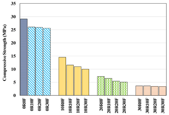
Figure 7.
Compressive strength of mortar mixes.
Figure 8 presents the compressive behavior of mortar with different percentage replacements of rubberized aggregate. Test results show slight reduction in the compressive strength with addition of metallic fibers (i.e., about 8%, which is not so significant). This reduction may be attributed due to the fact that the packing of the matrix is disturbed and compressive strength of the fiber-reinforced mortar is primarily dependent upon fiber-matrix bond. Also, the fibers used in current research is hydrophobic in nature and contribute lesser towards compressive strength enhancement. Results obtained for compressive strength of repair mortars incorporating steel fibers and rubber aggregates are in good agreement with previous research studies [5,8,20].
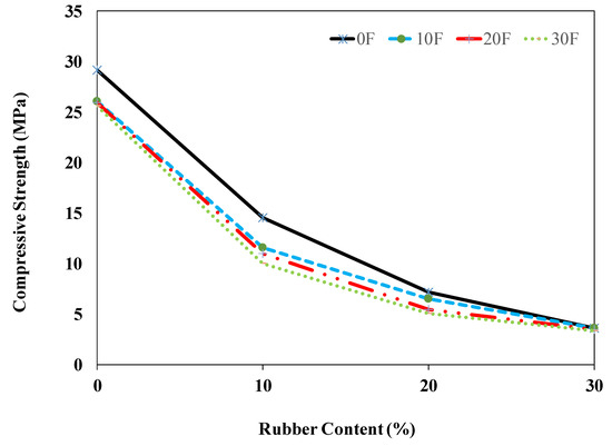
Figure 8.
Compressive strength with different percentages of rubber aggregates.
5.2. Modulus of Elasticity
Modulus of elasticity results of different mortar mixtures are shown in Figure 9. For each mix, three samples were tested. The test results of MOE in compression for all mortar mixtures with different replacements of rubber aggregates are presented in Figure 10. Results revealed that with the addition of steel fibers in the mortar mixture, there was a negligible reduction in modulus of elasticity. Further, the modulus of elasticity decreased with the increased content of rubber aggregates. It can be observed that with a 30% partial replacement of natural aggregate with rubber aggregate, the modulus of elasticity is reduced by around 60%. This reduction in MOE may be attributed to the lesser stiffness of rubber aggregates. Similar findings are reported by previous researchers [30]. This reduction may be attributed to poor bonding between cement paste and rubber aggregate and low modulus of elasticity of rubber aggregate according to the rule of mixture law [8].
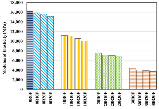
Figure 9.
Modulus of elasticity of mortar mixtures.
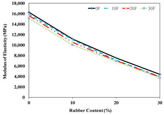
Figure 10.
Modulus of elasticity with different percentages of rubber aggregates.
5.3. Compression Toughness
Compression toughness was calculated by obtaining the area under. the stress-strain. curve up to 60% of peak load. Compression toughness results of all mortar mixes are presented in Figure 11. Test results of compressive toughness for all mortar mixtures with different fiber contents are presented in Figure 12. Compression toughness of mortar mixes with a combination of steel fibers and rubber aggregates showed significant reduction with an increment of rubber content and there was a minor increment with the addition of steel fibers. The reduction in compression toughness due to the addition of rubber aggregates was mainly due to low. stiffness. of rubber and the bond. defects. at rubber-cement. paste. interface. These experimental results are in good agreement with the study carried out on compressive toughness of rubberized steel fiber reinforced concrete [20].
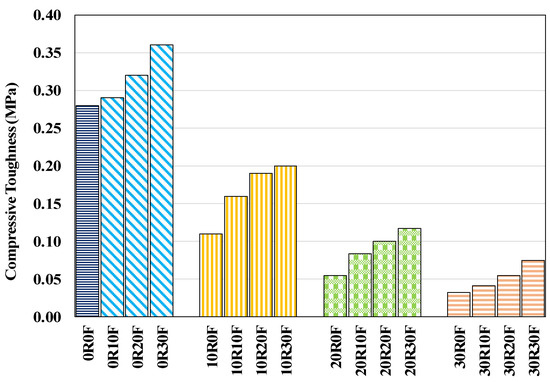
Figure 11.
Compression toughness of mortar mixes.
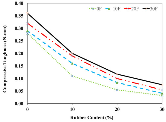
Figure 12.
Compression toughness of mortar mixes with different rubber content.
5.4. Relationship between Force and Deflection
The relationship between force and deflection of composite prisms having different types of repair materials are presented in Figure 13, Figure 14, Figure 15, Figure 16 and Figure 17. The curve of each repair mix composition represents the average of three prism specimens.
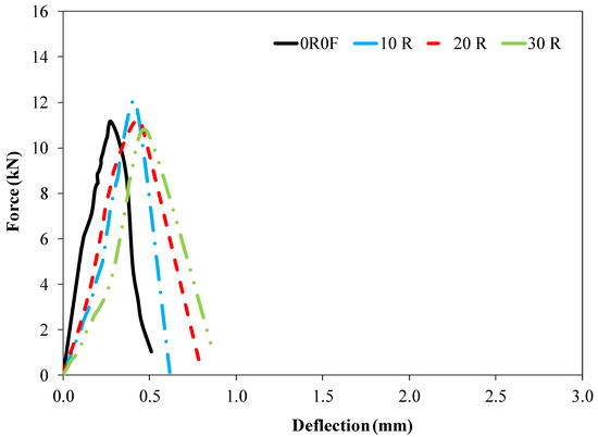
Figure 13.
Load versus deflection curve for composite beams with 0R0F, 10R0F, 20R0F, and 30R0F repair mix composition.
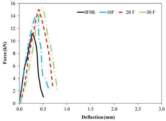
Figure 14.
Load versus deflection curve for composite beams with 0R0F, 0R10F, 0R20F, and 0R30F repair mix composition.
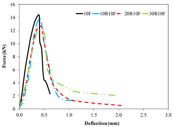
Figure 15.
Load versus deflection curve for composite beams with 10F, 10R10F, 20R10F, and 30R10F repair mix composition.
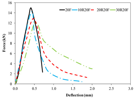
Figure 16.
Load versus deflection curve for composite beams with 0R20F, 10R20F, 20R20F, and 30R20F repair mix composition.
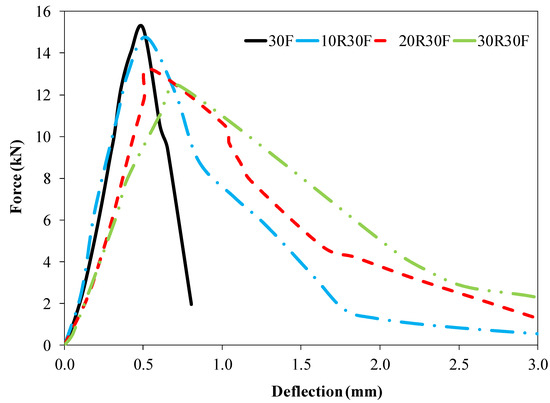
Figure 17.
Load versus deflection curve for composite beams with 0R30F, 10R30F, 20R30F, and 30R30F repair mixture composition.
The curves show that peak load as well as the corresponding deflection increased as compared to the control mortar with fiber reinforcement of repair material. The deflection capacity of material at ultimate load was increased with addition of rubber aggregate and steel fibers. The synergetic effect of rubber aggregates and metallic fibers was ensured through decreased cracking and improved ductility of repaired material. With the increase of fiber content in repaired beams, the post-peak residual strength also increased. The increase in the deflection of the composite prisms was due to the bridging action provided by the steel fibers against the crack opening. Similarly, an increase in peak load and corresponding deflection was observed in recent study conducted on rubberized fiber-reinforced overlays [44].
5.5. Flexural Strength
Flexural strength results of all composite prisms studied in this research program are presented in Figure 18. Flexural strength slightly decreased with the increment of rubber content and slightly increased with the increase in fiber content. These results showed the same trend as shown by the compressive strength, but the reduction rate is lesser than that of compressive strength results.
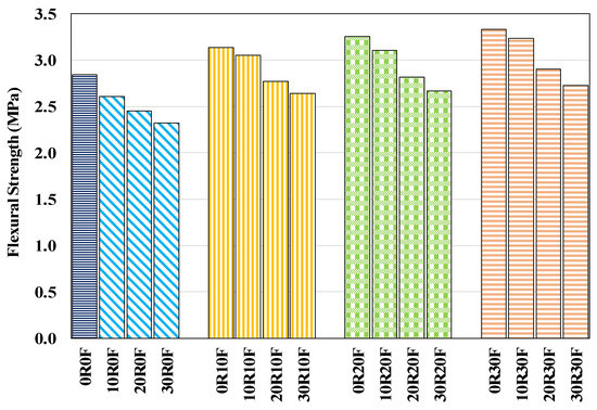
Figure 18.
Flexural strength of different mortar mixes.
5.6. Flexural Toughness
Flexural toughness was calculated by obtaining the area. under. the stress-strain. curve. up to 60% of. peak. load. Flexural toughness results of all of the mortar mixes studied in this research program are shown in Figure 19. The average flexural strength of the control prism came out to be 2.84 MPa. The flexural toughness of mortar mix incorporating 10 kg/m3, 20 kg/m3 and 30 kg/m3 of amorphous metallic fibers came out to be 4 MPa, 5.3 MPa and 5.8 MPa with the increment of 42%, 89%, and 107%, respectively. With the 10%, 20% and 30% replacement ratios of rubber content, the flexural toughness improved to 3.2 MPa, 4.4 MPa, and 4.6 MPa, respectively, with increments of 14%, 57%, and 64%, respectively, as compared to the control prism. Results indicated that with the increase in rubber aggregates, there is an increase in the flexural toughness of composite prisms.
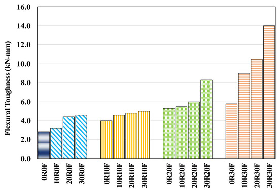
Figure 19.
Flexural toughness of composite prisms.
Results showed. that fiber. reinforcement. of mortar. showed an increment in flexural toughness. For composite prism with repair mix composition of 10R10F, 20R10F and 30R10F, the average flexural toughness was 4.6 MPa, 4.8 MPa and 5 MPa. The increment rate was 64%, 71%, and 78%, respectively, as compared to that of the flexural toughness of composite prism with a repair mix composition of 0R0F. Similarly, for composite prism with repair mix composition of 10R20F, 20R20F and 30R20F, the average flexural toughness was 5.5 MPa, 6 MPa, and 8.3 MPa with increases of 96%, 114%, and 196%, respectively.
For composite prisms with repair mix composition of 0R30F, 20R30F, and 30R30F, the average flexural strength of composite prisms was 9 MPa, 10.5 MPa, and 14 MPa with the increment rate of 221%, 275%, and 400%, respectively.
Flexural toughness is enhanced considerably in the presence of rubber content. Deformability of mortar is improved by incorporating rubber as it reduced the local stresses which occur around micro-cracks. It was noticed that the rubberized fiber-reinforced composites especially 30R30F exhibited more toughness as compared to the other mixtures, demonstrating the synergetic effect produced by the combined use of fibers and rubber aggregates in repair material. This enhancement in flexural toughness can also be validated from the previous research carried out on the flexural toughness of concrete incorporating both crumb rubber and steel fibers [35].
5.7. Relationship between Force and Crack Mouth Opening Displacement (CMOD)
The relationship. between. force. and CMOD of composite. prisms having. different types of repair materials. are presented in Figure 20, Figure 21, Figure 22, Figure 23 and Figure 24. The curve of each repair mix composition represents the average of three prism specimens.
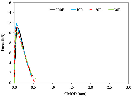
Figure 20.
Load versus CMOD curve for composite beams with 0R0F, 10R, 20R, and 30R repair mix composition.
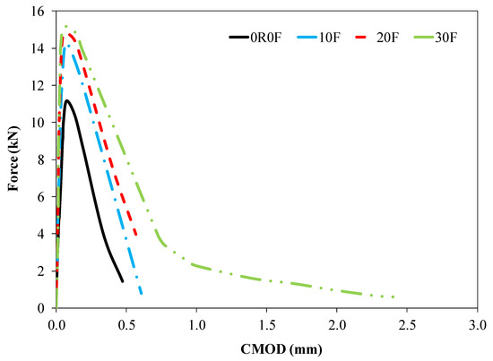
Figure 21.
Load versus CMOD curve for composite beams with 0R0F, 10F, 20F, and 30F repair mix composition.
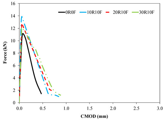
Figure 22.
Load versus CMOD curve for composite beams with 0R0F, 10R10F, 20R10F, and 30R10F repair mix composition.
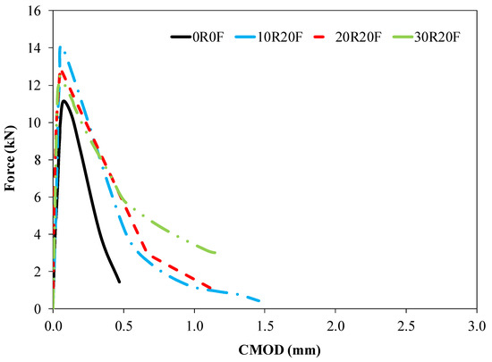
Figure 23.
Load versus CMOD curve for composite beams with 0R0F, 10R20F, 20R20F, and 30R20F repair mix composition.
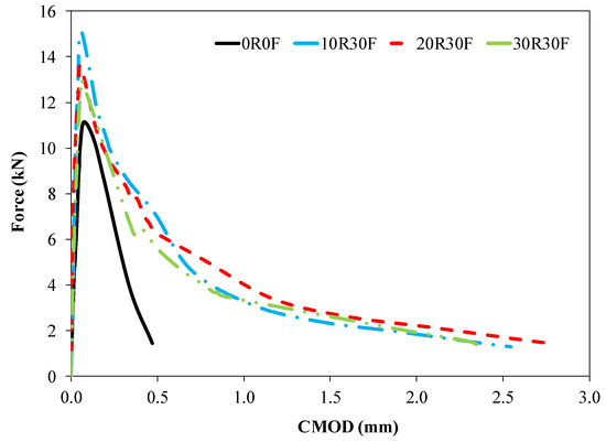
Figure 24.
Load versus CMOD curve for composite beams with 0R0F, 10R30F, 20R30F and 30R30F repair mix composition.
It was observed from the load versus CMOD curves that at any notch opening value, the corresponding value of force was higher as compared to the control mortar, especially, for the composite beams with the repair mixtures incorporating higher steel fiber content. For example, at a notch opening of 0.3 mm the corresponding force is 6 kN, 9.8 kN, 10.2 kN and 12 kN for 0R0F, 0R10F, 0R20F and 0R30F, respectively, as shown in Figure 21. These results also revealed that the steel fibers reinforcement played an important role in controlling notch opening and retraining the cracks under flexure loading. In the post-peak region, steel fibers control the cracks from further propagating by bridging action and provide higher post-peak residual strength. The values of CMOD at peak load are presented in Figure 25. The results revealed that rubber incorporation controls the notch opening up to the peak load by delaying micro-crack propagation to become macro cracks. For instance, at peak load the highest notch opening is observed for 0R0F (i.e., about 74 μm) and minimum for 30R0F (i.e., 44 μm).

Figure 25.
CMOD values at peak load for different repair mix compositions.
The CMOD values at post-peak load (i.e., 50% of peak load) are presented in Figure 26. In the post-peak region, steel fiber actively plays its role in controlling the notch opening by providing bridging action, but the rubber does not show a significant impact in controlling the notch opening in the post-peak region.
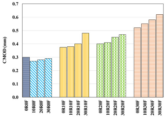
Figure 26.
CMOD values in post-peak region (at 50% peak load) for different repair mix compositions.
6. Conclusions
This research work was conducted to investigate the structural performance of fiber-reinforced and rubberized thin bonded cement-based overlays. The following conclusions can be drawn from the experimental results.
- Compressive strength, modulus of elasticity, flexural strength and compression toughness reduced with the increase of rubber content while there was no significant change with the increase of steel fibers. For 10R10F repair composite, there was a decrease of 60%, 32%, 2.5%, and 60% in compressive strength, MOE, flexural strength and compression toughness, respectively. It shows reduction in flexural strength is almost negligible.
- Fiber-reinforced rubberized cement-based composites exhibited higher flexural toughness. Among the different compositions studied, the flexural toughness for 30R30F improved up to 400%. Also, the synergetic effect has been observed by the combined use of fibers and rubber aggregates.
- At any notch opening value (CMOD), the corresponding force was higher for the composites beams repaired with mixtures incorporating higher steel fiber content as compared to the control mortar.
- Before peak load, rubber aggregates play their role by delaying the micro-crack propagation. In the post-peak region, steel fibers enhance the post-peak residual strength due to bridging action.
- The maximum crack restriction was shown by the repair material including fibers with or without the inclusion of rubber aggregates.
- Combine use of rubber aggregates and metallic fibers in a repair material of bonded cement-based overlays could be a suitable way to delay crack propagation and debonding.
- This research will facilitate the environment related issue for the utilization of rubber in construction industry with additional benefit of improving the structural and durability performance leading to more sustainable infrastructures.
Author Contributions
Conceptualization, A.J. and S.A.A.G.; Data curation, A.J.; Formal analysis, S.A.A.G.; Investigation, W.A. and R.H.; Methodology, A.J., S.A.A.G., W.A. and M.R.R.; Project administration, M.R.R.; Resources, S.A.A.G., M.R.R., S.A. and A.S.; Software, A.J.; Validation, W.A.; Visualization, W.A., R.H., S.A., A.S. and A.F.D.; Writing—original draft, A.J. and S.A.A.G.; Writing—review & editing, W.A., M.R.R., R.H., S.A., A.S. and A.F.D. All authors have read and agreed to the published version of the manuscript.
Funding
This research received no external funding.
Institutional Review Board Statement
Not applicable.
Informed Consent Statement
Not applicable.
Data Availability Statement
Not applicable.
Acknowledgments
The authors acknowledge the support of Saint Gobain Seva France for providing the fibers which were used in this study.
Conflicts of Interest
The authors declare no conflict of interest.
References
- Mehta, P.K. Concrete. Structure, Properties and Materials; Prentice-Hall: Englewood Cliffs, NJ, USA, 1986; Available online: https://trid.trb.org/view/273357 (accessed on 19 May 2022).
- Bissonnette, B.; Courard, L.; Fowler, D.W.; Granju, J.-L. Bonded Cement-Based Material Overlays for the Repair, the Lining or the Strengthening of Slabs or Pavements: State-of-the-Art Report of the RILEM Technical Committee 193-RLS; Springer Science & Business Media: Berlin/Heidelberg, Germany, 2011; Volume 3. [Google Scholar]
- Granju, J.L. Thin bonded overlays: About the role of fiber reinforcement on the limitation of their debonding. Adv. Cem. Based Mater. 1996, 4, 21–27. [Google Scholar] [CrossRef]
- Tran, Q.T.; Toumi, A.; Granju, J.-L. Experimental and numerical investigation of the debonding interface between an old concrete and an overlay. Mater. Struct. 2006, 39, 379–389. [Google Scholar] [CrossRef]
- Nguyen, T.H.; Toumi, A.; Turatsinze, A. Mechanical properties of steel fibre reinforced and rubberised cement-based mortars. Mater. Des. 2010, 31, 641–647. [Google Scholar] [CrossRef]
- Toumi, A.; Nguyen, T.-H.; Turatsinze, A. Debonding of a thin rubberised and fibre-reinforced cement-based repairs: Analytical and experimental study. Mater. Des. 2013, 49, 90–95. [Google Scholar] [CrossRef]
- Tran, Q.-T.; Toumi, A.; Turatsinze, A. Thin bonded cement-based overlays: Numerical analysis of factors influencing their debonding under fatigue loading. Mater. Struct. 2007, 41, 951–967. [Google Scholar] [CrossRef]
- Turatsinze, A.; Bonnet, S.; Granju, J.-L. Mechanical characterisation of cement-based mortar incorporating rubber aggregates from recycled worn tyres. Build. Environ. 2005, 40, 221–226. [Google Scholar] [CrossRef]
- Gillani, S.A.A.; Toumi, A.; Turatsinze, A. Effect of incorporating rubber aggregates and fiber reinforcement on the durability of thin bonded cement-based overlays. In Proceedings of the 8th RILEM International Conference on Mechanisms of Cracking and Debonding in Pavements, Nantes, France, 7–9 June 2016; pp. 619–625. [Google Scholar]
- Gillani, S.A.A. Degradation of the Residual Strength of Concrete: Effect of Fiber-Reinforcement and of Rubber Aggregates, Application to Thin Bonded Cement-Based Overlays. Ph.D. Thesis, Université Toulouse III-Paul Sabatier, Toulouse, France, 2017. [Google Scholar]
- Noaman, A.T.; Bakar, B.H.A.; Akil, H.M. Investigation on the mechanical properties of rubberized steel fiber concrete. Eng. Struct. Technol. 2017, 9, 79–92. [Google Scholar] [CrossRef]
- Nayar, S.K.; Gettu, R. Synergy in toughness by incorporating amorphous metal and steel fibers. ACI Mater. J. 2015, 112, 821–827. [Google Scholar] [CrossRef]
- Miller, N.M.; Tehrani, F.M. Mechanical properties of rubberized lightweight aggregate concrete. Constr. Build. Mater. 2017, 147, 264–271. [Google Scholar] [CrossRef]
- Turatsinze, A.; Measson, M.; Faure, J.-P. Rubberised concrete: From laboratory findings to field experiment validation. Int. J. Pavement Eng. 2016, 19, 883–892. [Google Scholar] [CrossRef]
- Issa, C.A.; Salem, G. Utilization of recycled crumb rubber as fine aggregates in concrete mix design. Constr. Build. Mater. 2013, 42, 48–52. [Google Scholar] [CrossRef]
- Marques, A.M.; Correia, J.R.; de Brito, J. Post-fire residual mechanical properties of concrete made with recycled rubber aggregate. Fire Saf. J. 2013, 58, 49–57. [Google Scholar] [CrossRef]
- Lee, J.W.; Jang, Y.I.; Park, W.S.; Kim, S.W. A study on mechanical properties of porous concrete using cementless binder. Int. J. Concr. Struct. Mater. 2016, 10, 527–537. [Google Scholar] [CrossRef]
- Shilar, F.A.; Ganachari, S.V.; Patil, V.B.; Khan, T.M.Y.; Khadar, S.D.A. Molarity activity effect on mechanical and microstructure properties of geopolymer concrete: A review. Case Stud. Constr. Mater. 2022, 16, e01014. [Google Scholar] [CrossRef]
- Alhawari, O.; Awan, U.; Bhutta, M.K.S.; Ülkü, M.A. Insights from Circular Economy Literature: A Review of Extant Definitions and Unravelling Paths to Future Research. Sustainability 2021, 13, 859. [Google Scholar] [CrossRef]
- Noaman, A.T.; Bakar, B.A.; Akil, H.M. Experimental investigation on compression toughness of rubberized steel fibre concrete. Constr. Build. Mater. 2016, 115, 163–170. [Google Scholar] [CrossRef]
- Al-Tayeb, M.M.; Bakar, B.H.A.; Akil, H.M.; Ismail, H. Performance of rubberized and hybrid rubberized concrete structures under static and impact load conditions. Exp. Mech. 2013, 53, 377–384. [Google Scholar] [CrossRef]
- Gillani, S.A.A.; Shahzad, S.; Toumi, A.; Turatsinze, A. Debonding of rubberised fibre-reinforced cement-based repairs under fatigue loading: Experimental study and numerical modelling. Int. J. Pavement Eng. 2021, 1–17. [Google Scholar] [CrossRef]
- Gillani, S.A.A.; Toumi, A.; Turatsinze, A. Cyclic bridging law of steel fibre-reinforced and rubberised cement-based materials. Eur. J. Environ. Civ. Eng. 2020, 26, 1336–1348. [Google Scholar] [CrossRef]
- Meshgin, P.; Xi, Y.; Li, Y. Utilization of phase change materials and rubber particles to improve thermal and mechanical properties of mortar. Constr. Build. Mater. 2012, 28, 713–721. [Google Scholar] [CrossRef]
- Akinshilo, A.T.; Davodi, A.G.; Rezazadeh, H.; Sobamowo, G.; Tunç, C. Heat transfer and flow of mhd micropolarnanofluid through the porous walls, magnetic fields and thermal radiation. Palest. J. Math. 2022, 11, 604–616. [Google Scholar]
- Khan, H.; Gómez-Aguilar, J.F.; Khan, A.; Khan, T.S. Stability analysis for fractional order advection–reaction diffusion system. Phys. A Stat. Mech. Appl. 2019, 521, 737–751. [Google Scholar] [CrossRef]
- Al-Asad, F.; Alam, N.; Tunç, C.; Sarker, M.M.A. Heat Transport Exploration of Free Convection Flow inside Enclosure Having Vertical Wavy Walls. J. Appl. Comput. Mech. 2021, 7, 520–527. [Google Scholar] [CrossRef]
- Noaman, A.T.; Bakar, B.A.; Akil, H.M.; Alani, A.H. Fracture characteristics of plain and steel fibre reinforced rubberized concrete. Constr. Build. Mater. 2017, 152, 414–423. [Google Scholar] [CrossRef]
- Ismail, M.K.; Hassan, A.A. An experimental study on flexural behaviour of large-scale concrete beams incorporating crumb rubber and steel fibres. Eng. Struct. 2017, 145, 97–108. [Google Scholar] [CrossRef]
- Gillani, S.A.A.; Riaz, M.R.; Hameed, R.; Qamar, A.; Toumi, A.; Turatsinze, A. Fracture energy of fiber-reinforced and rubberized cement-based composites: A sustainable approach towards recycling of waste scrap tires. Energy Environ. 2022, 0958305X221089223. [Google Scholar] [CrossRef]
- Centonze, G.; Leone, M.; Aiello, M.A. Steel fibers from waste tires as reinforcement in concrete: A mechanical characterization. Constr. Build. Mater. 2012, 36, 46–57. [Google Scholar] [CrossRef]
- Khan, M.; Cao, M.; Xie, C.; Ali, M. Effectiveness of hybrid steel-basalt fiber reinforced concrete under compression. Case Stud. Constr. Mater. 2022, 16, e00941. [Google Scholar] [CrossRef]
- Bu, C.; Zhu, D.; Liu, L.; Lu, X.; Sun, Y.; Yan, Z.; Yu, L.; Wei, Q. A Study on the Mechanical Properties and Microcosmic Mechanism of Basalt Fiber Modified Rubber Ceramsite Concrete. Buildings 2022, 12, 103. [Google Scholar] [CrossRef]
- Noaman, A.T.; Bakar, B.A.; Akil, H.M. The effect of combination between crumb rubber and steel fiber on impact energy of concrete beams. Procedia Eng. 2015, 125, 825–831. [Google Scholar] [CrossRef][Green Version]
- Bakar, B.A.; Noaman, A.T.; Akil, H.M. Cumulative effect of crumb rubber and steel fiber on the flexural toughness of concrete. Eng. Technol. Appl. Sci. Res. 2017, 7, 1345–1352. [Google Scholar] [CrossRef]
- Tayeh, B.A.; Bakar, B.H.A.; Johari, M. Characterization of the interfacial bond between old concrete substrate and ultra high performance fiber concrete repair composite. Mater. Struct. 2012, 46, 743–753. [Google Scholar] [CrossRef]
- Mirmoghtadaei, R.; Mohammadi, M.; Samani, N.A.; Mousavi, S. The impact of surface preparation on the bond strength of repaired concrete by metakaolin containing concrete. Constr. Build. Mater. 2015, 80, 76–83. [Google Scholar] [CrossRef]
- Garbacz, A.; Courard, L.; Kostana, K. Characterization of concrete surface roughness and its relation to adhesion in repair systems. Mater. Charact. 2006, 56, 281–289. [Google Scholar] [CrossRef]
- Sabah, S.A.; Hassan, M.H.; Bunnori, N.M.; Johari, M.M. Bond strength of the interface between normal concrete substrate and GUSMRC repair material overlay. Constr. Build. Mater. 2019, 216, 261–271. [Google Scholar] [CrossRef]
- Gillani, S.A.A.; Toumi, A.; Turatsinze, A. Effect of surface preparation of substrate on bond tensile strength of thin bonded cement-based overlays. Int. J. Pavement Res. Technol. 2020, 13, 197–204. [Google Scholar] [CrossRef]
- Hasani, M.; Nejad, F.M.; Sobhani, J.; Chini, M. Mechanical and durability properties of fiber reinforced concrete overlay: Experimental results and numerical simulation. Constr. Build. Mater. 2020, 268, 121083. [Google Scholar] [CrossRef]
- Gillani, S.A.A.; Shakir, A.S.; Toumi, A.; Turatsinze, A. Fiber-Reinforced and Rubberized Cement-Based Composite: A Sustainable Repair Material for Thin Bonded Overlays. 2017. Available online: https://scholar.google.com/citations?view_op=view_citation&hl=en&user=w8Ca5HIAAAAJ&sortby=pubdate&citation_for_view=w8Ca5HIAAAAJ:WF5omc3nYNoC (accessed on 18 June 2022).
- Toumi, A.; Nguyen, T.-H.; Turatsinze, A. Modelling of the debonding of steel fibre reinforced and rubberised cement-based overlays under fatigue loading. Eur. J. Environ. Civ. Eng. 2015, 19, 672–686. [Google Scholar] [CrossRef]
- Gillani, S.A.A.; Shahzad, S.; Abbass, W.; Abbas, S.; Toumi, A.; Turatsinze, A.; Mohamed, A.M.; Sayed, M.M. Debonding of Thin Bonded Rubberised Fibre-Reinforced Cement-Based Repairs under Monotonic Loading: Experimental and Numerical Investigation. Materials 2022, 15, 3886. [Google Scholar] [CrossRef]
- Polypropylene Synthetic Microfiber, Monofilament. Available online: https://tenabrix.com/concrete-fiber/?lpads02 (accessed on 18 June 2022).
- Abbass, W.; Khan, M.I.; Mourad, S. Evaluation of mechanical properties of steel fiber reinforced concrete with different strengths of concrete. Constr. Build. Mater. 2018, 168, 556–569. [Google Scholar] [CrossRef]
- Vandewalle, L.; Nemegeer, D.; Balazs, L.; di Prisco, M. Rilem TC 162-TDF: Test and design methods for steel fibre reinforced concrete: Uni-axial tension test for steel fibre reinforced concrete. Mater. Struct. Mater. Constr. 2001, 34, 3–6. [Google Scholar]


Publisher’s Note: MDPI stays neutral with regard to jurisdictional claims in published maps and institutional affiliations. |
© 2022 by the authors. Licensee MDPI, Basel, Switzerland. This article is an open access article distributed under the terms and conditions of the Creative Commons Attribution (CC BY) license (https://creativecommons.org/licenses/by/4.0/).