Article

The Flexural Performance of BFRP-Reinforced UHPC Beams Compared to Steel and GFRP-Reinforced Beams

Department of Civil Engineering, College of Engineering, American University of Sharjah, Sharjah 26666, United Arab Emirates
*
Author to whom correspondence should be addressed.
Sustainability 2022, 14(22), 15139; https://doi.org/10.3390/su142215139
Submission received: 29 September 2022 / Revised: 2 November 2022 / Accepted: 12 November 2022 / Published: 15 November 2022
(This article belongs to the Special Issue High Performance and Advanced Construction Materials)

Abstract

:
The performance of ultra-high-performance concrete (UHPC) reinforced with BFRP bars was investigated in this research study. To achieve the objectives of this study, a total of six UHPC beams were cast and tested for flexure, under displacement-controlled loading conditions. The performance of BFRP-reinforced beams was compared against GFRP and steel reinforced beams. All beams had a cross-section of 185 mm × 250 mm, and a total length of 2200 mm. The experimental results were presented and discussed in terms of cracking moments, cracking patterns, failure modes, flexural capacity, midspan deflection, as well as strains in concrete and reinforcement. Results showed that UHPC enhanced the flexural performance of BFRP-reinforced beams in terms of moment capacity, deflection response and cracking patterns. The experimental results were complimented with analytical results that were calculated using the ACI 440 and CAN/CSA S806 code provisions. It was found that moment predictions using relevant ACI equations are acceptable for under-reinforced beams, but were slightly unconservative for the over-reinforced beams.

1. Introduction

Concrete structures are typically reinforced with steel, which has a major drawback associated with corrosion particularly in the Gulf region with a hot and humid weather cover most of the year. Corrosion in reinforcing steel can cause premature deterioration of concrete structures, which can lead to tremendous economic loses, due to the need of repair. Furthermore, steel production is ranked third among industries with the largest carbon footprints [1]. The process of manufacturing steel used in the construction industry is estimated to be responsible for releasing 1.85 tons of CO2 emissions for every ton of steel produced [2]. Hence, in attempts to build more sustainable and eco-friendly structures, alternative reinforcement materials, such as fiber-reinforced polymers (FRP), are being investigated.
For the past few decades, fiber-reinforced polymer (FRP) has been studied by researchers as an alternative material to steel for reinforcing concrete. FRP bars are available commercially in a variety of types, such as Glass FRP (GFRP), Carbon FRP (CFRP), and Aramid FRP (AFRP). Recently, the newly developed Basalt FRP (BFRP) bars are emerging as an alternative for steel reinforcement due to their excellent mechanical performance. One of the main advantages of using FRP bars as reinforcement for concrete is their non-corrosive nature, which is a very appealing aspect for structures constructed in coastal areas as well as for bridges and dams. In addition, FRP bars are characterized by their high tensile strength and light weight.
While FRP bars offer a wide range of advantages over conventional reinforcement, the use of such bars is still limited in the construction industry due to some drawbacks. Among these drawbacks are the low ductility possessed by FRP bars, the weak bond between the FRP bars and the concrete, brittle failure, low modulus of elasticity, and weak performance at elevated temperatures. Current design codes and provisions such as the ACI 440.1R [3] and CAN/CSA S806 [4] allow the use of FRP as a reinforcing material with limitations and guidelines for the design.
Due to their advantages, the research on FRP bars has increased in recent years in attempts to overcome or mitigate their disadvantages, which can help produce a more sustainable structure. Previous research on the flexural [5,6,7,8,9,10,11,12,13,14] and shear [15,16,17,18,19] behavior of FRP-reinforced beams were collected and reviewed. Abdelkarim et al. [6] studied the serviceability and strength of concrete beams reinforced for flexure with GFRP bars. Four different bar sizes (12, 16, 20 and 25 mm) and two concrete compressive strengths (35 and 65 MPa) were considered in the study. It was evident from the test results using higher concrete strength resulted in a 41.2% increase in the moment capacity, and an improvement in the cracking response. In another study conducted by Abed and Alhafiz [8], the flexural strength of fiber reinforced concrete beams reinforced with BFRP and GFRP bars was investigated. It was found that introducing basalt fibers to the concrete increased curvature ductility of the beams. Furthermore, the beams reinforced with GFRP and BFRP bars achieved a higher flexural capacity of 15% and 28%, respectively, than beams reinforced with steel bars. Al-Hamrani and Alnahhal conducted research to study the shear behavior of concrete beams reinforced with GFRP and BFRP bars and stirrups [15]. It was observed that using FRP stirrups as shear reinforcement resulted in significant reduction in load carrying capacity, which was explained to be a result of lower axial stiffness possessed by the GFRP stirrups compared to steel stirrups.
FRP bars are often not utilized to their maximum capacity as a result of concrete failure occur way before the ultimate stress of the bars is achieved, which leads to uneconomical use of the material. Using high compressive strength concrete to cast FRP-reinforced beams helps in taking advantage of the unutilized capacities of FRP bars. Ultra-high-performance concrete (UHPC) is an advanced composite material developed to cope with current advancement in high-rise buildings and super-span bridges. These advancements constantly demand a higher form of concrete capable of performing better in terms of strength and durability. The incorporation of high cement content, low water-binder ratio, and steel fibers produces a concrete that can reach compressive strengths of 120 MPa and higher, providing safe, durable, and economical designs achieve a very dense and homogenous microstructure with good ductility.
An extensive literature review revealed a limited number of studies on the topic of using UHPC with FRP bars in concrete beams [20,21,22]. Yoo et al. [20] investigated the flexural behavior of GFRP-reinforced concrete beams cast with UHPC with consideration of various reinforcement ratios. Test results showed that beams having higher reinforcement ratio exhibited improved ultimate moment capacity, ductility, and deformability. It was also recommended that available ACI formulations overestimated the ultimate moment capacity of UHPC beams reinforced with FRP bars. Abbas et al. [21] conducted a numerical study to investigate the flexural behavior of UHPC beams reinforced with steel-FRP composite bars. Several parameters were investigated such as the inner steel core area ratio of the composite bars, the yield strength of inner steel core, the tensile properties of outer-wrapped FRP, reinforcement ratio, and the compressive strength of the concrete. The results showed that the flexural performance of the beams was most affected by the inner steel core area ratio of the composite bars, the reinforcement ratio and the modulus of elasticity of the outer FRP wrapping. In another study by Goldston et al. [22], the flexural behavior of high strength concrete (HSC) and UHPC beams reinforced with GFRP bars was investigated. It was concluded that the use of higher strength concrete resulted in creating reserve capacity or pseudo “ductility” for beams designed as over-reinforced as opposed to under-reinforced beams.
The combination of UHPC and FRP reinforcement can result in several advantages, such as resolving the corrosion problem due to steel reinforcement which enhances the durability of concrete structures. Furthermore, relying on UHPC can reduce the dimensions and the amount of reinforcement needed for structural components to resist the applied loads, resulting in reduced cost and dead weights. In addition, the fibers incorporated in the UHPC mix can enhance the ductility of members and tone down the lower ductility of FRP bars. Previous research supports that the high mechanical properties of the FRP bars were better employed when concrete with higher strengths were used [5,11]. In recent years, the research on FRP as a reinforcing material is gaining popularity in an attempt by researchers to promote the use of FRP products for more sustainable designs. For instance, Zhao et al. [23] investigated the flexural performance of concrete beams reinforced with carbon-FRP (CFRP) and GFRP bars subjected to elevated temperatures. In another study [24], the performance of light weight aggregate concrete beams reinforced with GFRP and BFRP bars was investigated. However, experimental studies on the flexural behavior of FRP-reinforced beams utilizing UHPC are very limited, in which only two published papers were found that studied GFRP-reinforced UHPC [20,22]. Furthermore, none of the published work investigated the flexural performance UHPC beams reinforced with BFRP bars.
This paper investigates the flexural behavior of UHPC beams reinforced with BFRP bars in terms of flexural capacity, deflection, strains in concrete and reinforcement, failure modes and cracking response. The main test parameters are the reinforcement ratio and type (BFRP vs GFRP and steel rebar). Furthermore, the test results are used to assess the applicability of the ACI 440 [3] and CSA S806 [4] design equations for FRP-reinforced beams constructed with UHPC.

2. Materials and Methods

In total, eight UHPC beams with a cross-section of 185 mm × 250 mm and a total span of 2200 mm were cast and tested under a four-point bending scheme, under displacement-controlled loading. The beams were simply supported on chairs made from structural steel with a 150 mm overhang to provide stability for the beams during testing and to ensure that the FRP bars have sufficient development length, leaving an effective span of 1900 mm. The bottom flexural reinforcement detail of each beam is provided in Table 1. All beams were reinforced with two No. 10 steel bars at the top for ease of constructability of the beams and to act as hangers for the stirrups. To ensure flexural failure, all beams were heavily reinforced in shear with two-legged No. 10 stirrups spaced at 100 mm. To seclude any interference in the results due to shear reinforcement, the middle span of 400 mm was free from any stirrups. The concrete clear cover to the stirrups was 40 mm from the bottom, 25 mm from the top, and 27.5 mm from the sides of the beam. Figure 1 provides a schematic diagram of the specimen detailing, test setup, and specimen instrumentation.
The primary focus of this paper is to study the performance of BFRP bars as flexural reinforcement in UHPC concrete beams. For this purpose, two different BFRP bar sizes of 10 and 20 mm were considered. Similar beams but reinforced with GFRP bars of 10 mm and 20 mm were cast for comparison purposes. Based on these bar diameters, one beam was designed as over-reinforced with a 𝜌𝑓/𝜌𝑓𝑏 ratio greater than 1, while the other was designed as a tension-controlled or under-reinforced section with the ratio being less than 1. Additionally, two beams reinforced with steel rebar of 12 and 16 mm were considered. The mechanical properties of the different rebar materials, which are listed in Table 2, were obtained from a previous study by the third author [25].
The UHPC concrete utilized in this study was provided by a local plant, in which short steel fibers were incorporated into the mix and the design compressive strength was 120 MPa. Table 3 provides the concrete mix proportions as obtained from the supplier. The actual compressive strengths of the cubes and cylinders were determined through the average of three specimens each, which were tested on the day of testing of the beams and are reported as 144 MPa and 110 MPa, respectively.
A simple identification scheme of the beams was deployed in this study. In the scheme, the first digit represents the number of bars in the tension zone, followed by a letter representing the type of reinforcement (B, sand-coated BFRP bars; G, sand-coated GFRP bars; and S, steel bars), followed by the size of the bar, and lastly a letter to identify the beams as under-reinforced or over-reinforced.
The testing of all beams was carried out using a UTM machine having a maximum loading capacity of 2000 kN. The loading was transmitted from the load cell onto a spreader beam resting on two 25 mm × 100 mm × 200 mm steel plates, spaced at 400 mm, which spans the constant moment region. All bottom-reinforcement bars were instrumented with strain gauges at midspan. In addition, the concrete strain at midspan was measured using a strain gauge fixed 10 mm below the top compression fibers of the beam. The deflection of each beam was measured at midspan using linear variable differential transducers (LVDTs) placed below the beam at the midpoint of the beam width.

3. Experimental Results

3.1. Moment vs. Deflection Relationship

During testing, the cracking behavior of all beams was monitored and the load at first crack was recorded. The maximum load and deflection were obtained from the data measured by the actuator and the LVDTs. All beams’ experimental nominal moment capacity was computed from the recorded data mentioned previously. The nominal and cracking moments (Mn and Mcr, respectively) were calculated using the ACI 440 [3] and CSA S806 [4] code equations. The dominating mode of failure was observed and recorded. All data are reported in Table 4.
The moments corresponding to the first crack loads were computed, and the values ranged from 10.78 to 13.49 kN·m. A comparison between predicted and experimental moments at cracking showed a good agreement. The ratio of the experimental to predicted moments was on average of 0.93 ± 0.06 and 0.96 ± 0.06 for the ACI 440 [3] and the CSA S806 [4], respectively.
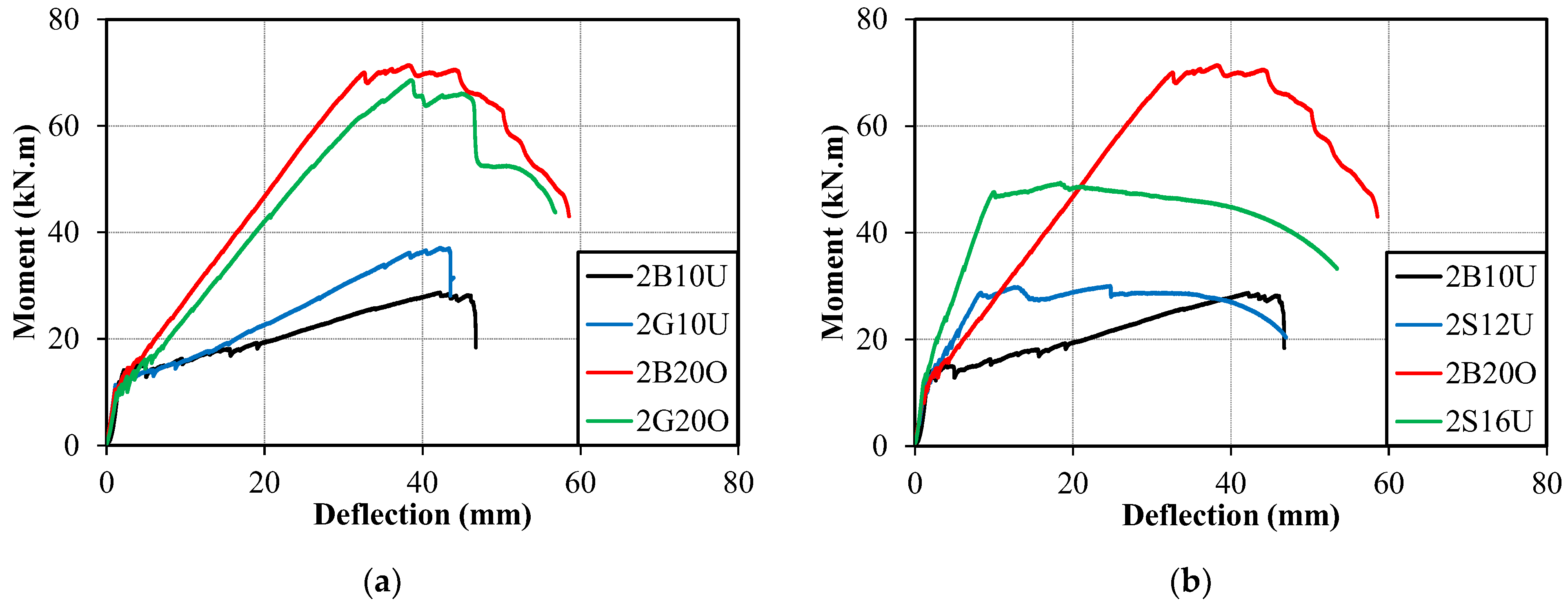
Figure 2 presents the moment versus deflection curves for all beams. The beams reinforced with FRP bars displayed a somewhat bilinear moment-deflection relation, in which a clear reduction in the post-cracking stiffness possessed by those beams can be observed. This can be seen from the drop in the post-cracking slopes. For the under-reinforced beams, the deflection behavior was linearly elastic until failure, indicating the lack of ductility in those beams. On the other hand, the over-reinforced beams (2B20O and 2G20O) displayed some amount of ductility before failure. Similar observations were reported by Goldston et al. [21] for HSC and UHPC beams.

3.1.1. BFRP vs. GFRP-Reinforced Beams

The moment versus deflection curves for the BFRP and GFRP-reinforced beams were plotted in Figure 2a. It can be observed that the GFRP and BFRP-reinforced beams had very similar flexural responses. On average, the initial cracking moment was 11.11 and 11.42 kN·m for BFRP- and GFRP-reinforced beams, respectively. Thus, it can be concluded that the first cracking moment was not influenced by the type of FRP reinforcement used. There was a distinction in the post-cracking stiffness between the four beams. Namely, beam 2G10U exhibited higher post-cracking stiffness than its counterpart (2B10U). On the other hand, the GFRP-reinforced beam 2G20O showed lower post-cracking stiffness than BFRP-reinforced beam 2B20O. This is explained by the larger modulus of elasticity possessed by the No. 10 GFRP and No. 20 BFRP (refer to Table 2).
Furthermore, beams 2B20O and 2G20O had similar flexural capacities, but beam 2G10U exhibited a higher flexural capacity of 29% compared to the 2T10B beam. There were also minor differences in the cracking patterns, failure modes, and midspan deflections between the GFRP- and BFRP-reinforced beams. The GFRP- and BFRP-reinforced beams generally showed similar flexural behavior. This indicates that BFRP bars can be used as alternatives to more traditional FRP reinforcement such as the GFRP bars, as they provide comparable behavior in flexure.

3.1.2. BFRP vs. Steel Reinforced Beams

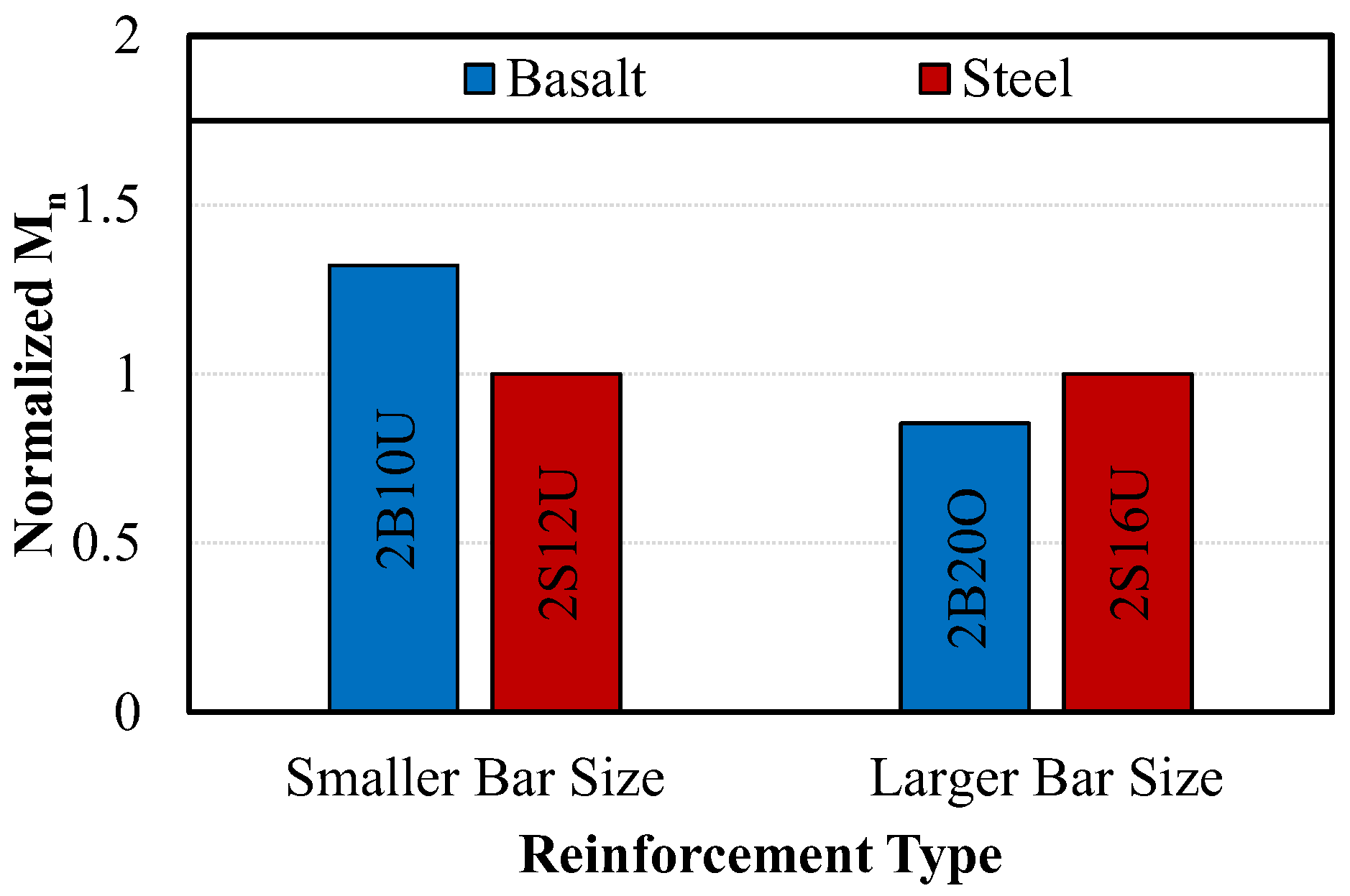
Comparison between the behavior of steel-reinforced beams and BFRP-reinforced beams can be found in Figure 2b. Due to the difference in the bar diameter of the steel and BFRP bars used, the nominal moment capacities were normalized with respect to the reinforcement ratio and plotted in Figure 3. This was done by multiplying the moment capacity of the FRP-reinforced beams by a factor reflecting the difference in the amount of reinforcement (As,steel/As,FRP), and then normalizing the results against the steel-reinforced beams.
It can be seen that the BFRP-reinforced beams performed better than steel-reinforced beams when a smaller bar size is used. When normalized, beam 2B10U achieved a nominal moment capacity 32% higher than beam 2S12U. This significant enhancement in the moment capacity is a result of the much higher tensile strength of the FRP bars as compared to that of steel bars. On the other hand, beam 2B20O recorded a 15% lower moment capacity than the steel-reinforced beam 2S16U, when normalized. This is mainly due to the fact that the BFRP-reinforced beam is compression-controlled, and thus the recorded moment capacity does not reflect the full utilization of the FRP strength.
On the other hand, the steel reinforced beams performed better than BFRP-reinforced beams in terms of midspan deflection, post-cracking stiffness, ductility, and moment at first crack. The midspan deflection was smaller for beams reinforced with steel than in BFRP-reinforced beams. Also, the beams reinforced with steel presented a much larger post-cracking stiffness than BFRP-reinforced beams, which is expected as a result of the lower elasticity of the BFRP bars in comparison with steel. In addition, the steel-reinforced beams reported higher cracking moments than their equivalent BFRP counterparts. Lastly, the 2S12U beam exhibited better ductility than the 2B10U beam.

3.2. Moment-Strain Relationship

The moment versus strain in the longitudinal flexural reinforcement is plotted in Figure 4. It is worth noting that the strain in the concrete and reinforcing bars, which corresponds to the ultimate load, of few specimens could not be determined. This is a consequence of strain gauges getting damaged during testing prior to reaching the ultimate load level. To solve this problem, a linear regression analysis similar to the one used by Goldston et al. [21] was used, which assumes a linear post-cracking strain behavior.
Prior to cracking, all beams showed similar behavior in terms of the tensile reinforcement strains. Once the cracking occurred, the beams experienced rapid increases in the reinforcement strains due to reduced stiffnesses. Closer inspection of the moment versus strain reveals that the 2B20O beam had a larger concrete strain (0.0038) at the top compression fibers than the 2B20O beam (0.003). However, both the GFRP and BFRP bars in the over-reinforced beams achieved around 85% of their rupture strain. The 2B10U and 2G10U beams had concrete strains of 0.0033 and 0.0036, respectively, and bar strains very close to the rupture strains. However, the over-reinforced beams sustained additional loads even after reaching the ultimate load. Hence, the beams failed at concrete crushing strains greater than 0.003–0.0037, but the exact values were not established due to the damage of the strain gauges. It was also found that the steel-reinforced beam, 2T12S, had the highest concrete strain at ultimate (0.0044). This shows that using UHPC can improve the concrete strain to values beyond 0.004.
Furthermore, the strain in the longitudinal reinforcement of the FRP-reinforced beams when the ultimate load was reached ranged between 1.8 and 2.2%, which corresponds to 70–85% of the ultimate strain of FRP bars. This shows that the use of UHPC allows for better utilization of FRP bars, resulting in better economy. It can be seen from Figure 4 that the reinforcement having a bigger diameter reached strain levels lower than those of beams having a smaller bar diameter. This is a result of concrete failure prior to reaching higher strain levels in the tension zone.

3.3. Failure Modes

Figure 5 shows the photos of the tested beams after failure. As indicated earlier, some of the beams in this study were designed to fail by FRP rupture/steel yielding (designated by U for under-reinforced) or by concrete crushing (designated by O for over-reinforced).
For the under-reinforced FRP RC beams, vertical cracks started appearing in the midspan region once the tensile strength of concrete was exceeded. As the load increased, the existing cracks propagated slowly towards the compressive zone, and new cracks formed around the midspan region. At higher loads, horizontal cracking along the tensile zone was observed, which indicated that the FRP bars were close to rupture. Also, flexural cracks in the midspan region kept on propagating towards the concrete top surface until the beams reached the maximum load and failed instantaneously. This caused some of the cracks at the midspan region to widen. The failure of under-reinforced beams occurred in a sudden and brittle manner due to the rupture of the FRP bars.
For the over-reinforced FRP RC beams, flexural cracks appeared in the midspan region at cracking moments averaging 10.9 kN·m. Upon increasing the load, the formation of cracks continued and the existing cracks propagated at a very slow rate. The crushing of concrete in the compression zone was first observed at moments averaging from 68.1 kN·m. During the initial crushing of concrete, the flexural cracks in the midspan section began to widen. However, the beams kept on sustaining the loads and deforming until the compression concrete was fully disintegrated; hence, the compressive failure of the over-reinforced beams was somewhat ductile in nature. This agrees well with the recommendations of the ACI and CSA of designing FRP-reinforced beams as compression-controlled to prevent sudden failure. The over-reinforced beams also showed smaller crack depths than the under-reinforced beams at failure.

4. Analytical Results

4.1. Flexural Capacity

In this study, the nominal flexural strength was calculated using formulations in the ACI 440 code [3] only, since they do not specify any upper limit for the compressive strength of the concrete. On the other hand, the CSA code [4] formulations are restricted to concrete strengths of less than 80 MPa. The ACI 318 code [26] recommendations were also used in estimating the flexural strengths of the steel-reinforced beams. Table 4 provides the experimental and predicted flexural strengths of all the beam specimens.
On average, the ratio of experimental to predicted flexural strength was found to be 1.01 ± 0.11 for the UHPC beams. This shows that the predicted values were in good agreement with the experimental results. For the FRP-reinforced beams, the ACI 440 code [3] was slightly unconservative, where the flexural strength was over-estimated by an average of 5.8%. However, the ACI 318 code [26] provided conservative estimates, as it under-predicted the flexural strength of the steel reinforced beams by an average of 15.5%.

4.2. Deflection

The midspan deflections (△i) of the FRP-reinforced beams were estimated using Equation (1). When calculating the effective moment of inertia (Ie) shown in Equation (2), the change in stiffness along the beam length was accounted for by introducing an integration factor (γ) computed using Equation (3) as recommended by the ACI 440 [3]. On the other hand, the CSA code [4] suggests the moment-curvature approach for determining the midspan deflections. In the CSA approach [4], the midspan deflections are estimated using Equation (1) for the un-cracked part, and using Equation (4) for the cracked part.
Δ i = P   a 48   E c   I   ( 3 L 2 4 a 2 )
I e = I c r 1 γ   ( M c r   M a ) 2 [ 1 I c r I g ]
γ = 1.72 0.72   ( M c r M a )
Δ i = P   L 3 48   E c   I c r [   3 ( a L ) 4   ( a L ) 3 8   η   ( L g L ) 3   ]
where P is the concentrated load applied, a is the sear span, Ec is the modulus of elasticity of concrete, I = Ig is the gross moment of inertia of the beam, L is the total span of the beam, Icr is the cracked section moment of inertia, Ma is the maximum applied moment, η is a coefficient equal to 1 I c r I g , and Lg is the uncracked length of the beam calculated as a   ( M c r M a ) .
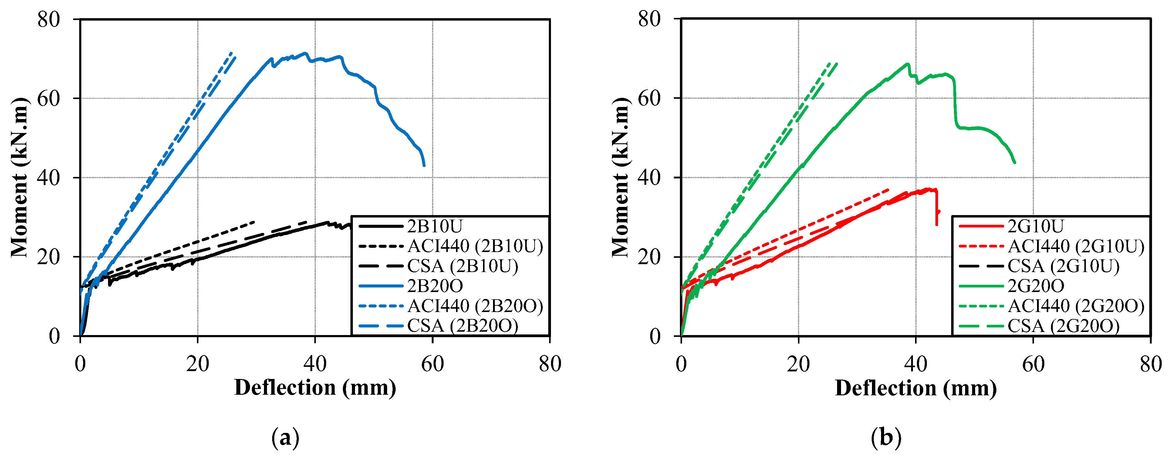
The experimental and predicted maximum midspan deflections corresponding to ultimate moments are presented in Table 5. Both ACI 440 [3] and CSA S806 [4] formulations underestimated the deflection levels of the FRP-reinforced beams, by 45 and 28%, respectively.
By estimating the flexural strength and deflection of the beams at cracking and ultimate states, an analytical moment versus midspan deflection curve of the UHPC-FRP beams can be plotted assuming a bilinear behavior, as shown in Figure 6. It can be seen that both the ACI [3] and CSA [4] codes were very unconservative, with the CSA code providing slightly better estimates. The midspan deflection was significantly under-estimated by the two codes, especially at the ultimate moment level. This shows that the ACI and CSA formulations for the midspan deflection of UHPC beams need further improvement.

5. Conclusions

This paper presented the results of a study investigating the flexural behavior of UHPC beams reinforced with BFRP bars and compared with GFRP- and steel-reinforced beams. The experimental results were complemented with analytical calculations obtained using the ACI 440.1R and CAN/CSA S806 recommendations. The following outcomes can be drawn based on the results of the study:
  • The UHPC beams reinforced with BFRP bars exhibited a typical bilinear behavior between the moment and deflections/strains. The overall behavior of BFRP-reinforced beams was very similar to that of the GFRP-reinforced beams. Once the cracking moment was exceeded, the BFRP- and GFRP-reinforced beams experienced a reduction in the bending stiffness, which was governed by the modulus of elasticity and amount of the reinforcement. On the other hand, steel-reinforced beams experienced a gradual reduction in stiffness until yielding.
  • For lower reinforcement ratios, the UHPC beams reinforced with BFRP bars reported a 23% decrease in the flexural capacity compared to the GFRP-reinforced beams, while a 4% increase in flexural capacity was recorded by the BFRP-reinforced beams over the GFRP-reinforced beams when a larger reinforcement ratio was utilized.
  • Based on normalized results with respect to reinforcement ratio between BFRP- and steel-reinforced beams, a clear dominance can be seen in favor of the BFRP-reinforced beams. This is attributed to the higher tensile strength of the BFRP reinforcement as compared to the yield strength of the steel. However, when a higher reinforcement ratio is used the BFRP-reinforced beam was defined by concrete failure and had a slightly lower moment capacity than the steel-reinforced beam.
  • The observed mode of failure of all beams followed the behavior of the beams as designed, in which over-reinforced beams failed by concrete crushing and under-reinforced beams failed by FRP rupture or steel yielding. Relying on concrete crushing of over-reinforced FRP beams resulted in an enhanced ductility of the UHPC beams. On the other hand, the under-reinforced FRP beams exhibited a linear moment-deflection curve until failure, which was brittle as a result of the rupture of FRP reinforcement.
  • Relying on concrete having high compressive strength resulted in better utilization of the FRP reinforcement, as evidenced by the utilized strain in the longitudinal FRP reinforcement. The strain values ranged between 1.8 and 2.2% when the ultimate load of the beams was reached, which corresponds to 70–85% of the ultimate strain of FRP bars.
  • Overall, the ACI 440.1R code equations reasonably predicted the nominal flexural capacity of BFRP-reinforced beams. In addition, both the ACI 440.1R and CSA S806 well predicted the cracking moments of the UHPC beams.
  • On average, the CSA S806 estimated the deflection values of the UHPC BFRP-reinforced beams better than the ACI 440.1R. However, the midspan deflection was significantly under-estimated by both codes when compared to the actual experimental values. This shows that the ACI 440.1R and CSA S806 formulations for the midspan deflection of UHPC beams need further improvement.

Author Contributions

Conceptualization, F.A.; Data curation, Y.A.; Formal analysis, Y.A., Z.M. and F.A.; Funding acquisition, F.A.; Investigation, Y.A., Z.M. and F.A.; Methodology, Y.A., Z.M. and F.A.; Project administration, F.A.; Resources, F.A.; Supervision, F.A.; Validation, Y.A. and Z.M.; Writing—original draft, Y.A.; Writing—review and editing, Z.M. and F.A. All authors have read and agreed to the published version of the manuscript.

Funding

The authors appreciate the financial support provided by the Office of Sponsored Research at the American University of Sharjah, UAE. The work in this paper was supported, in part, by the Open Access Program from the American University of Sharjah. This paper represents the opinions of the authors and does not mean to represent the position or opinions of the American University of Sharjah.

Institutional Review Board Statement

Not applicable.

Informed Consent Statement

Not applicable.

Data Availability Statement

Not applicable.

Conflicts of Interest

The authors declare no conflict of interest.

References

  1. Hammond, G.P.; Jones, C.I. Embodied energy and carbon in construction materials. Proc. Inst. Civ. Eng. Energy 2008, 161, 87–98. [Google Scholar] [CrossRef] [Green Version]
  2. Purnell, P. The carbon footprint of reinforced concrete. Adv. Cem. Res. 2013, 25, 362–368. [Google Scholar] [CrossRef] [Green Version]
  3. ACI Committee 440. Guide for the Design and Construction of Structural Concrete Reinforced with Fiber-Reinforced Polymer (FRP) Bars; ACI 440.1R-15; American Concrete Institute: Farmington Hills, MI, USA, 2015. [Google Scholar]
  4. Canadian Standard Association. Design and Construction of Building Structures with Fibre-Reinforced Polymers; CSA-S806-12; CSA: Mississauga, ON, Canada, 2012. [Google Scholar]
  5. El-Nemr, B.A.; Ahmed, E.A.; Benmokrane, B. Flexural Behavior and Serviceability of Normal- and High-Strength Concrete Beams Reinforced with Glass Fiber-Reinforced Polymer Bars. ACI Struct. J. 2013, 110. [Google Scholar] [CrossRef]
  6. Abdelkarim, O.I.; Ahmed, E.A.; Mohamed, H.M.; Benmokrane, B. Flexural strength and serviceability evaluation of concrete beams reinforced with deformed GFRP bars. Eng. Struct. 2019, 186, 282–296. [Google Scholar] [CrossRef]
  7. El-Nemr, A.; Ahmed, E.A.; El-Safty, A.; Benmokrane, B. Evaluation of the flexural strength and serviceability of concrete beams reinforced with different types of GFRP bars. Eng. Struct. 2018, 173, 606–619. [Google Scholar] [CrossRef]
  8. Abed, F.; Alhafiz, A.R. Effect of basalt fibers on the flexural behavior of concrete beams reinforced with BFRP bars. Compos. Struct. 2019, 215, 23–34. [Google Scholar] [CrossRef]
  9. Alkhraisha, H.; Mhanna, H.; Tello, N.; Abed, F. Serviceability and Flexural Behavior of Concrete Beams Reinforced with Basalt Fiber-Reinforced Polymer (BFRP) Bars Exposed to Harsh Conditions. Polymers 2020, 12, 2110. [Google Scholar] [CrossRef]
  10. Adam, M.; Said, M.; Mahmoud, A.A.; Shanour, A.S. Analytical and experimental flexural behavior of concrete beams reinforced with glass fiber reinforced polymers bars. Constr. Build. Mater. 2015, 84, 354–366. [Google Scholar] [CrossRef]
  11. Abed, F.; Al-Mimar, M.; Ahmed, S. Performance of BFRP RC beams using high strength concrete. Compos. Part C Open Access 2021, 4, 100107. [Google Scholar] [CrossRef]
  12. Xie, Y.; Zhuo, K.; Rashid, K.; Deng, J.; Zhang, F. Flexural Performance of BFRP Bar Reinforced High-Strength Concrete Beam. In Proceedings of the International Conference on Fibre-Reinforced Polymer (FRP) Composites in Civil Engineering, Istanbul, Turkey, 8–10 December 2021; pp. 111–120. [Google Scholar]
  13. Rashid, M.A.; Mansur, M.A.; Paramasivam, P. Behavior of Aramid Fiber-Reinforced Polymer Reinforced High Strength Concrete Beams under Bending. J. Compos. Constr. 2005, 9, 117–127. [Google Scholar] [CrossRef]
  14. Erfan, A.M.; Hassan, H.E.; Hatab, K.M.; El-Sayed, T.A. The flexural behavior of nano concrete and high strength concrete using GFRP. Constr. Build. Mater. 2020, 247, 118664. [Google Scholar] [CrossRef]
  15. El Refai, A.; Abed, F. Concrete Contribution to Shear Strength of Beams Reinforced with Basalt Fiber-Reinforced Bars. J. Compos. Constr. 2016, 20. [Google Scholar] [CrossRef]
  16. Abed, F.; Sabbagh, M.K.; Karzad, A.S. Effect of basalt microfibers on the shear response of short concrete beams reinforced with BFRP bars. Compos. Struct. 2021, 269, 114029. [Google Scholar] [CrossRef]
  17. Abed, F.; El Refai, A.; Abdalla, S. Experimental and finite element investigation of the shear performance of BFRP-RC short beams. Structures 2019, 20, 689–701. [Google Scholar] [CrossRef]
  18. Al-Hamrani, A.; Alnahhal, W.; Elahtem, A. Shear behavior of green concrete beams reinforced with basalt FRP bars and stirrups. Compos. Struct. 2021, 277, 114619. [Google Scholar] [CrossRef]
  19. Al-Hamrani, A.; Alnahhal, W. Shear behavior of basalt FRC beams reinforced with basalt FRP bars and glass FRP stirrups: Experimental and analytical investigations. Eng. Struct. 2021, 242, 112612. [Google Scholar] [CrossRef]
  20. Yoo, D.-Y.; Banthia, N.; Yoon, Y.-S. Predicting service deflection of ultra-high-performance fiber-reinforced concrete beams reinforced with GFRP bars. Compos. Part B Eng. 2016, 99, 381–397. [Google Scholar] [CrossRef]
  21. Abbas, E.M.; Ge, Y.; Zhang, Z.; Chen, Y.; Ashour, A.; Ge, W.; Tang, R.; Yang, Z.; Khailah, E.Y.; Yao, S.; et al. Flexural behavior of UHPC beam reinforced with steel-FRP composite bars. Case Stud. Constr. Mater. 2022, 16, e01110. [Google Scholar] [CrossRef]
  22. Goldston, M.; Remennikov, A.; Sheikh, M.N. Flexural behaviour of GFRP-reinforced high strength and ultra high strength concrete beams. Constr. Build. Mater. 2017, 131, 606–617. [Google Scholar] [CrossRef] [Green Version]
  23. Zhao, J.; Pan, H.; Wang, Z.; Li, G. Experimental and Theoretical Study on Flexural Behavior of GFRP- and CFRP-Reinforced Concrete Beams after High-Temperature Exposure. Polymers 2022, 14, 4002. [Google Scholar] [CrossRef] [PubMed]
  24. Abed, M.A.; Anagreh, A.; Tošić, N.; Alkhabbaz, O.; Alshwaiki, M.E.; Černý, R. Structural Performance of Lightweight Aggregate Concrete Reinforced by Glass or Basalt Fiber Reinforced Polymer Bars. Polymers 2022, 14, 2142. [Google Scholar] [CrossRef] [PubMed]
  25. Al Rifai, M.; El-Hassan, H.; El-Maaddawy, T.; Abed, F. Durability of basalt FRP reinforcing bars in alkaline solution and moist concrete environments. Constr. Build. Mater. 2020, 243, 118258. [Google Scholar] [CrossRef]
  26. ACI 318 Committee. Building Code Requirements for Structural Concrete and Commentary, 1st ed.; American Concrete Institute: Farmington Hills, MI, USA, 2019. [Google Scholar]
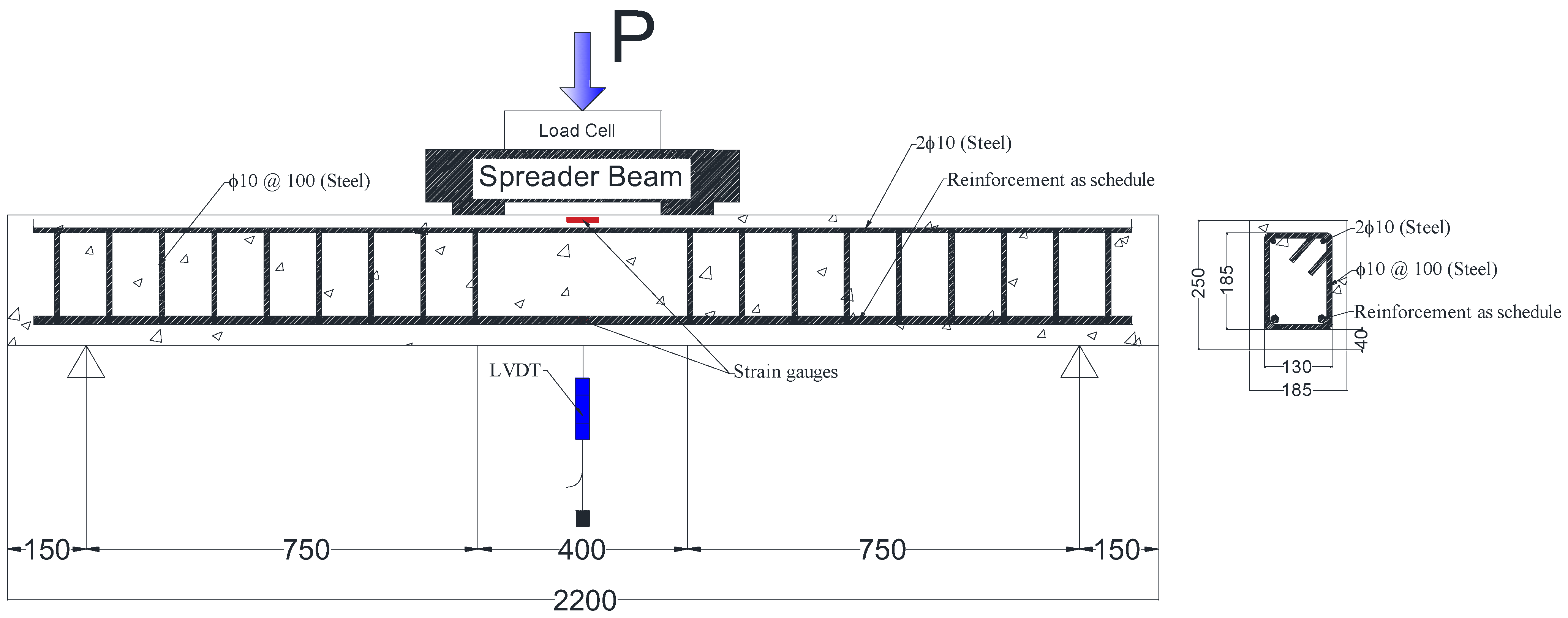
Figure 1. Specimens detailing, test setup, and specimen instrumentation.
Sustainability 14 15139 g001
Figure 2. Moment versus deflection curves comparing: (a) BFRP vs GFRP; (b) BFRP vs. Steel.
Sustainability 14 15139 g002
Figure 3. Normalized nominal moment with respect to reinforcement ratio.
Sustainability 14 15139 g003
Figure 4. Moment versus strain in the longitudinal reinforcement.
Sustainability 14 15139 g004
Figure 5. Failure mode of tested beams.
Sustainability 14 15139 g005aSustainability 14 15139 g005b
Figure 6. Comparison between analytical and experimental moment versus deflection relation for: (a) BFRP; (b) GFRP-reinforced beams.
Sustainability 14 15139 g006
Table 1. Details of test matrix.
Beam IDBar TypeBar Diameter (mm)ρf (%)ρffb
2B10UBFRP100.420.66
2B20OBFRP201.782.07
2G10UGFRP100.500.65
2G20OGFRP201.761.53
2S12USteel120.580.11
2S16USteel161.050.19
Table 2. Tensile properties of flexural reinforcement.
Bar
Type
Bar Diameter (mm)Bar Area
(mm2)
Ultimate Strength (MPa)Modulus of Elasticity (GPa)Photo
BFRP1080.11028.742.8Sustainability 14 15139 i001
BFRP20328.191345.9Sustainability 14 15139 i002
GFRP1094.196043.1Sustainability 14 15139 i003
GFRP20325.377946.1Sustainability 14 15139 i004
Steel12110.3 *575200Sustainability 14 15139 i005
Steel16195.8 *568200Sustainability 14 15139 i006
* Yield strength of steel bars.
Table 3. Concrete mix proportions.
MaterialProportion
Cement700 kg/m3
Water140 kg/m3
20 mm aggregate560 kg/m3
10 mm aggregate365 kg/m3
Washed sand450 kg/m3
Dune sand305 kg/m3
Micro silica150 kg/m3
Superplasticizer10 l/m3
Table 4. Summary of experimental and predicted results.
BeamExperimentalExperimental/PredictedFailure
Mode
Mn (kN·m)δ (mm)Mcr (kN·m)Mcr (ACI)Mcr (CSA)Mn (ACI)
2B10U28.7346.4011.710.930.970.88TC
2B20O71.4144.5711.130.890.920.93CC
2G10U37.1243.3211.430.910.941.05TC
2G20O68.6046.3810.780.860.890.91CC
2S12U30.0524.7312.440.991.031.18TC
2S16U49.3719.0613.491.081.111.13TC
Average---0.940.981.01-
Stand. Dev.---0.070.070.11-
TC: Tension Controlled; CC: Compression Controlled.
Table 5. Experimental and predicted deflections corresponding to ultimate moment.
BeamMeasured Deflection
(mm)
Predicted Deflection (mm) δ e x p / δ p r e
ACI 440CSA S806ACI 440CSA S806
2B10U43.3235.5641.781.221.04
2B20O38.5125.2526.481.531.45
2G10U46.4029.4838.391.571.21
2G20O38.3225.7026.851.491.43
Average---1.451.28
Standard Deviation---0.140.17
Publisher’s Note: MDPI stays neutral with regard to jurisdictional claims in published maps and institutional affiliations.