Abstract
The stress diffusion characteristics of reinforced soil retaining walls (RSW) with concrete-block panels under cyclic loads are studied. The distribution of the vertical dynamic earth pressure caused by an external load and the analysis of stress diffusion angles were studied using a model test and the numerical simulation model of the reinforced soil retaining wall was established to analyze the change in the stress diffusion angle. We then changed the parameters to investigate the influencing factors of the stress diffusion characteristics. The results showed that: the average value of the peak vertical dynamic earth pressure caused by an external load at the loading position of the RSW was a nonlinear distribution, decaying from top to bottom and increasing with the increase in the loading amplitude, while the change in the loading frequency number of loading cycles had no obvious rule. The results of model test and numerical simulation agree with each other. The diffusion angle of the stress caused by the external load of the reinforced body was basically between 50° and 65° in the range from 1.8 m to 1.2 m, the diffusion angle at the top was slightly larger than the middle, and the diffusion angle away from the wall was larger than the diffusion angle close to the wall. The main factors affecting the stress diffusion in reinforced soil retaining walls are the coefficient of reinforcement of the soil and the dynamic stress amplitude; the stress diffusion angle increased with an increase in the coefficient of the reinforcement of the soil and the dynamic stress amplitude. The conclusion of this paper can provide a reference for the design of reinforced soil structures.
1. Introduction
In this study, highway- and railway-reinforced soil retaining wall structures are subjected to the combined effect of static and dynamic loads. The loads and the number of cycles are large, which can lead to large structural deformations, so the mechanical behavior of reinforced soil retaining walls under cyclic loads has attracted the attention of scholars. Many scholars [1,2,3,4,5,6,7,8,9,10], through model tests and numerical simulations, have found that a reinforced body makes the soil more structural, expands the range of soil involved in bearing, and that the distribution of the soil pressure attenuation coefficient along the wall height of reinforced soil retaining walls varies according to the length and type of the reinforcement. Mohsen Kargar [11], through a laboratory model of a fixed and rigid retaining wall with a cohesionless dry backfill measured under the effect of static and repeated loads, have found that models show a significant increase in the earth pressure due to cyclic loading compared to static loading, especially in the initial cycles of loading. Ding et al. [12]., through a series of laboratory experiments, have found the central effective soil pressure is exponentially distributed and decays with the increasing distance from the vibration source and Luo et al. [13]., through reinforcement treatment tests of soft rock subgrade, have found that the attenuation of the dynamic soil pressure of the roadbed laid with geocell is more obvious than that of the roadbed laid with geogrid.
At present, studies of the factors affecting stress diffusion characteristics of retaining walls are lacking for highway- and railway-reinforced soil retaining walls; moreover, the predecessors only proposed that reinforcement would increase the stress diffusion range and did not analyze the factors affecting the stress diffusion range. For highway- and railway-reinforced soil retaining walls, stress diffusion caused by external loads is a main factor influencing the retaining wall working characteristics and the stress diffusion angle is an important parameter to design the retaining wall and the roadbed. As a result, the cyclic load transfer law of diffusion in the reinforced soil retaining wall is significant for analyzing the force and deformation law of reinforced soil retaining walls and can also provide a reference for the design of retaining walls and roadbeds. In this paper, on the basis of the predecessors’ research, a laboratory model test of modular reinforced soil retaining walls is carried out to analyze the rule of the vertical dynamic earth pressure due to external loads and stress diffusion characteristics under different loading amplitudes, and loading frequencies and number of loading cycles and establish a numerical analysis model, put forward five factors affecting the stress diffusion, then analyze the influences of different factors on the stress diffusion of reinforced soil retaining walls under cyclic loads. The conclusion of this paper can provide a theoretical basis for the study of the influence factors of the stress diffusion of the reinforced soil structures and provide a reference for the design of the reinforced soil structures.
2. Experimental Study
According to the test model box size and loading system, and in order to cause the test results to more truly reflect the stress diffusion characteristics of reinforced soil retaining walls under cyclic loads, different model scale sizes were analyzed and discussed and then the geometric similarity constant CL = 4 was determined. The similarity constant of soil elastic modulus CE = 1. The similarity constant of geogrids tensile modulus CEr = 4.
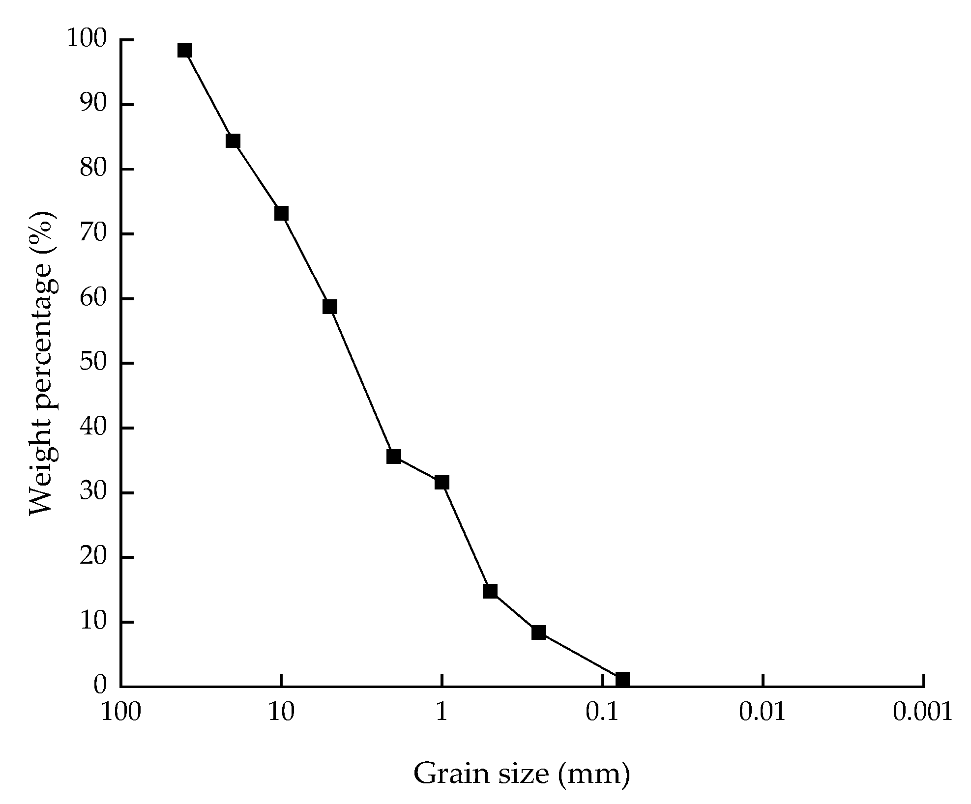
2.1. Wall Filling
The filling of the retaining wall was gravel soil [1]. The curve of the particle size analysis of gravel soil is shown in Figure 1 and Table 1 lists the physical characteristics of the soil.

Figure 1.
Curve of particle size analysis of gravel soil.

Table 1.
Physical characteristics of the wall filling.
2.2. Reinforcement
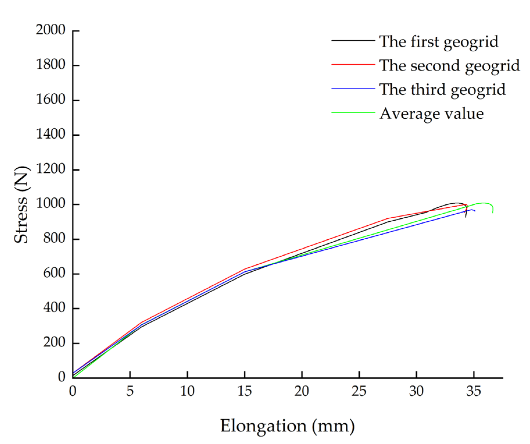
The reinforcement in the reinforced soil was high-density polyethylene (HDPE) uniaxial geogrids [1]. The tensile curve of uniaxial geogrids is shown in Figure 2; this is the tensile test curve of one rib along the force direction of the geogrid, with 40 ribs per meter. Table 2 lists the average values of the main characteristics of the three geogrids.
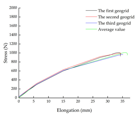
Figure 2.
Tensile curve of uniaxial geogrids.
Table 2.
The mechanical characteristics of the geogrids.
2.3. Model Size and Monitoring Instrument Arrangement
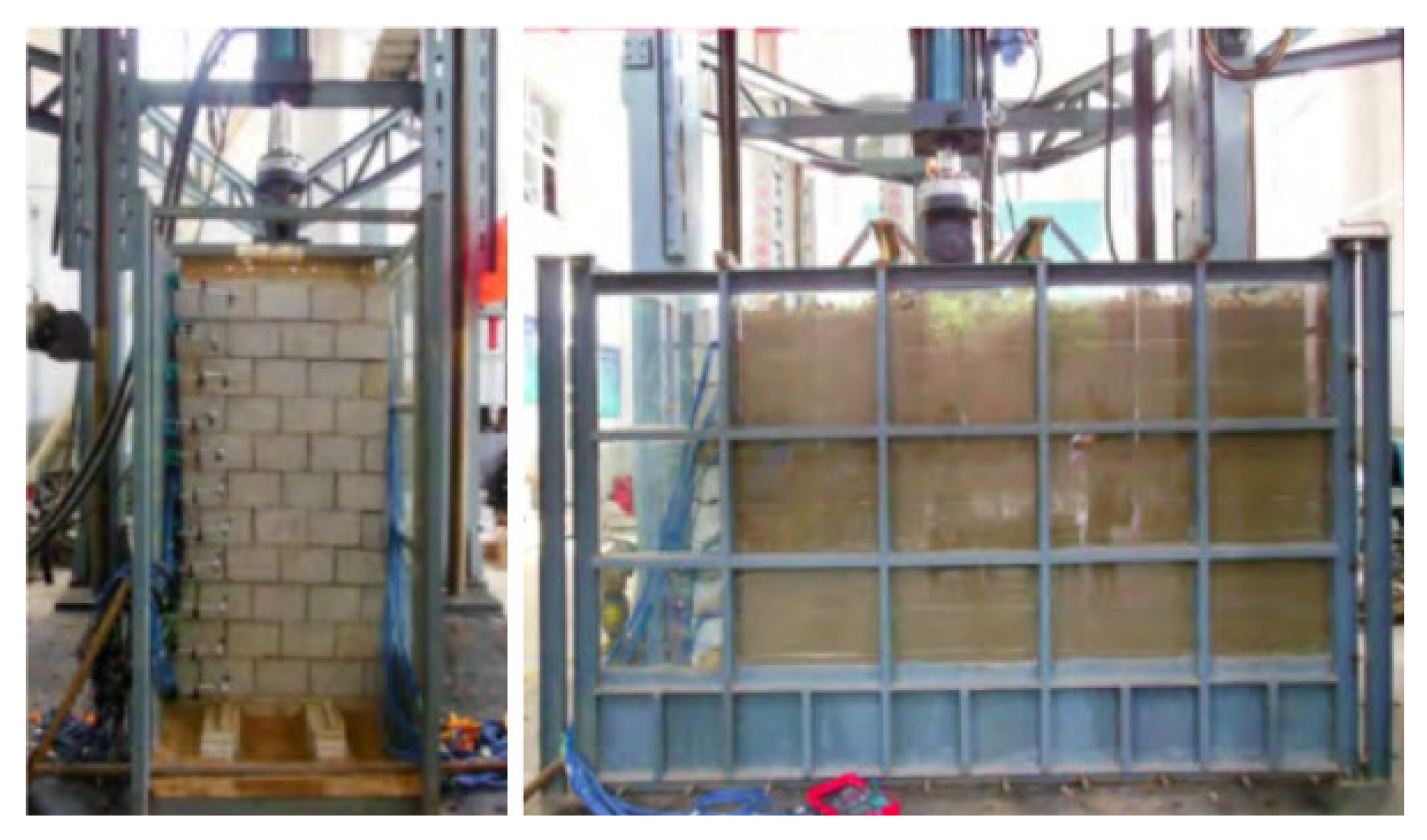
According to the laboratory model test [1], the RSW model was 3.0 m (L) × 1.0 m (W) × 1.8 m (H), with a wall slope ratio of 1:0.05. The model box wall was coated with lubricant to reduce friction. The model box skeleton was enhanced at the top, the test elements were centrally buried in the middle, and the side walls were not deformed during the test, ensuring plane strain conditions. A photo of the model box is shown in Figure 3.
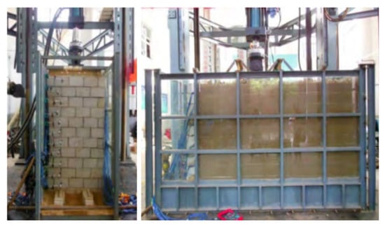
Figure 3.
Photo of the model box.
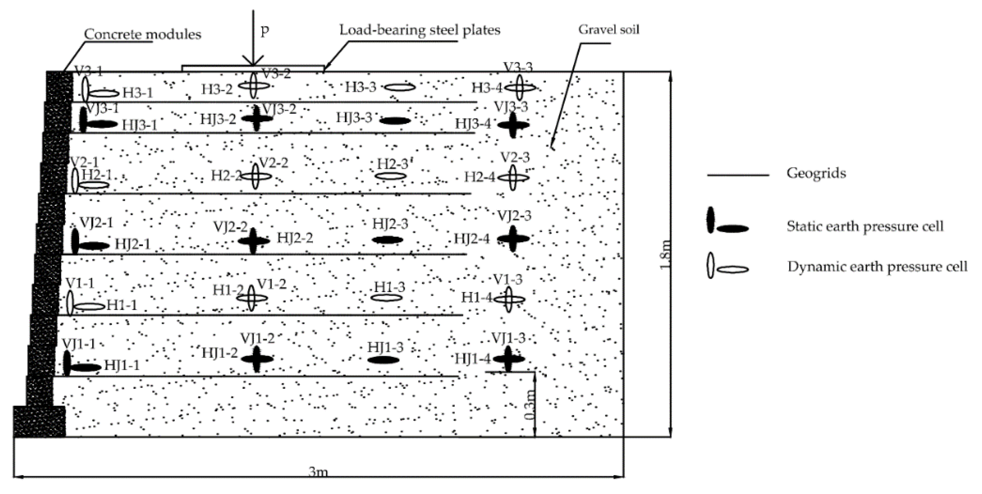
The test elements with the parameters are shown in Table 3 and the RSW dimensions and monitoring instrument arrangement were as shown in Figure 4.
Table 3.
Test element parameters.

Figure 4.
Reinforced soil retaining wall dimensions and monitoring instrument arrangement.
2.4. Filling Requirements and Loading Scheme
After the compaction tests [1], the controlling indices of compaction were as listed in Table 4. When high-speed railway trains are running, the high frequency vibration brought by the uneven track cannot affect the reinforced earth retaining wall due to the action of the track bed. The cyclic load acting on the retaining wall is transferred by the train car load through the wheel. According to the measured dynamic stress values of high-speed railway subgrade at home and abroad [1], the loading amplitudes of the test are determined to be 60–80 kPa, 60–100 kPa, and 60–120 kPa. According to the traffic loading frequency of the roadbed filling during its service period, it is between 0.1 Hz and 10 Hz [14] and the train base frequency has a great influence on the roadbed; the test determined four loading frequencies: 4 Hz, 6 Hz, 8 Hz, and 10 Hz. The vertical cyclic loads were applied at the top and sine wave type loading was used, with 100,000 times cyclic load added under each condition, for a total of 1.2 million times.
Table 4.
Filling control indicators.
3. Analysis of Model Test Results
3.1. Analysis of Vertical Dynamic Earth Pressure Due to External Loads
3.1.1. Vertical Dynamic Earth Pressure along the Wall Height
According to the laboratory model test, the average of the peak vertical dynamic earth pressure caused by an external load is shown in Figure 5. The average of the peak vertical dynamic earth pressure caused by an external load at the loading position of the RSW increased with the increase in the loading amplitude, while the effect of the loading frequency was not obvious; the average of the peak vertical dynamic earth pressure caused by an external load with the height of the retaining wall was non-linear. From top to bottom, there was a trend of decay and the decay rate of the upper part was smaller than that of the lower part. This was because: the upper part of the retaining wall had less geogrids, the reinforcement effect was poor, and it was close to the loading position, so the stress decay rate was slower, while there were more layers of reinforcement downwards and the load brought its tensile properties fully into play, so the reinforcement effect was good and the stress decay rate was faster.
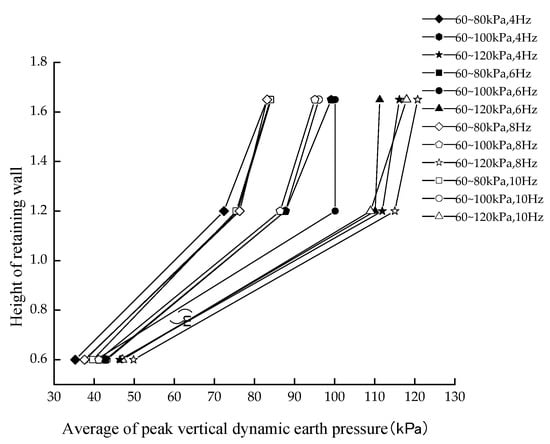
Figure 5.
Distribution of vertical dynamic earth pressure near panel along wall height.
3.1.2. Vertical Dynamic Earth Pressure with the Increase in Load Cycle Number
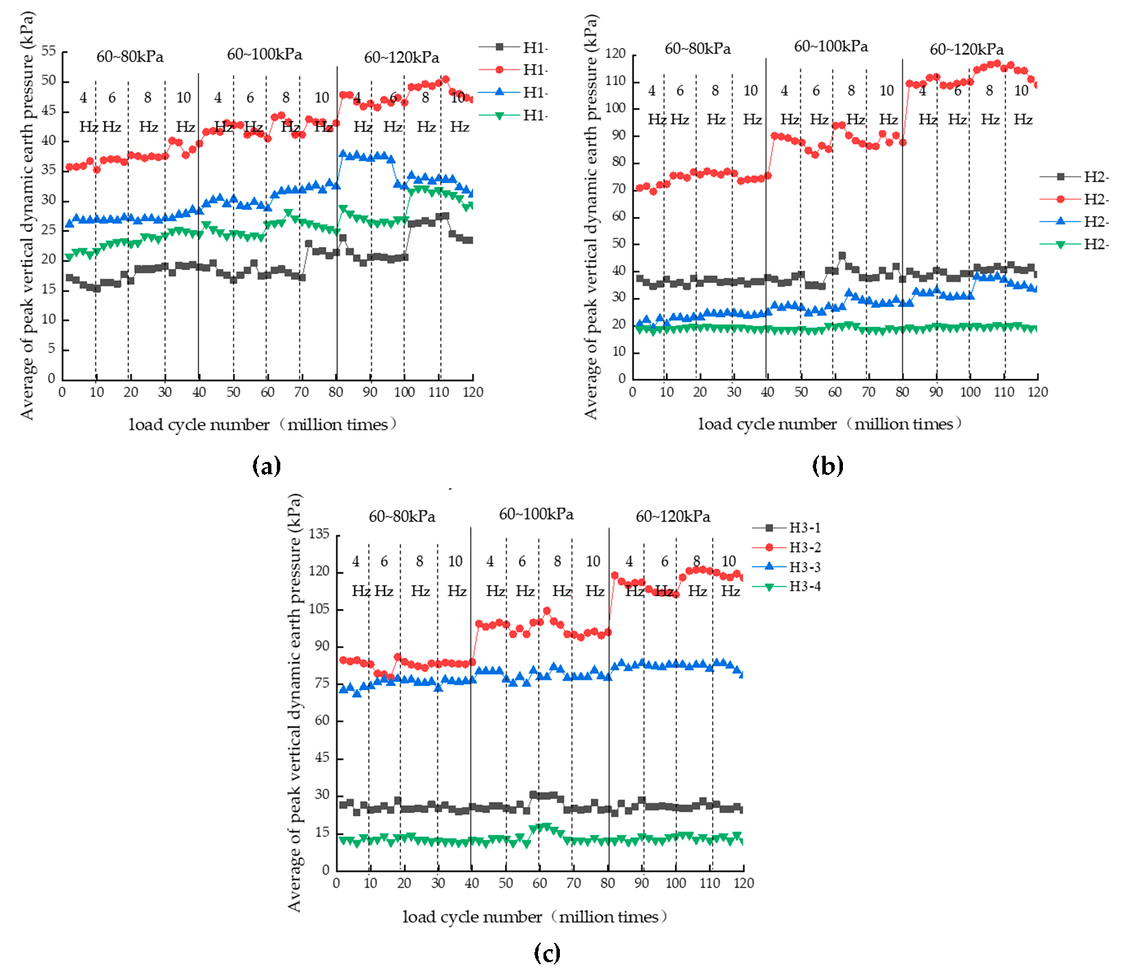
With the increase in loading times, the vertical earth pressure changed as shown in Figure 6. On the whole, H3-2 and H2-2, close to the loading position, showed a sudden increase after the change in the load value. The closer the loading position was, the greater the increase in earth pressure was, which was mainly influenced by the diffusion and attenuation of additional stress. With the increase in load cycles, the vertical earth pressure near the panel basically stayed the same or slightly decreased, because the horizontal displacement of the wall released part of stress. Under the condition of a constant load, with the increase in cycle times and loading frequency, the dynamic earth pressure changed little. This was mainly because the stiffness of the reinforced body was very large due to the interaction between the soil and the reinforcement. Under the action of vibration, the soil soon reached the maximum compactness, so the vertical earth pressure changed little when the load was unchanged. The main factors affecting the vertical earth pressure were load value, the number of load cycles, and the loading frequency change; the vertical earth pressure was less affected.
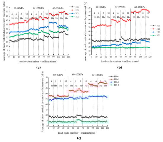
Figure 6.
Distribution of vertical dynamic earth pressure with an increase in the load cycle number; (a) h = 0.6 m; (b) h = 1.2 m; (c) h = 1.65 m.
3.2. Analysis of Stress Diffusion Characterization
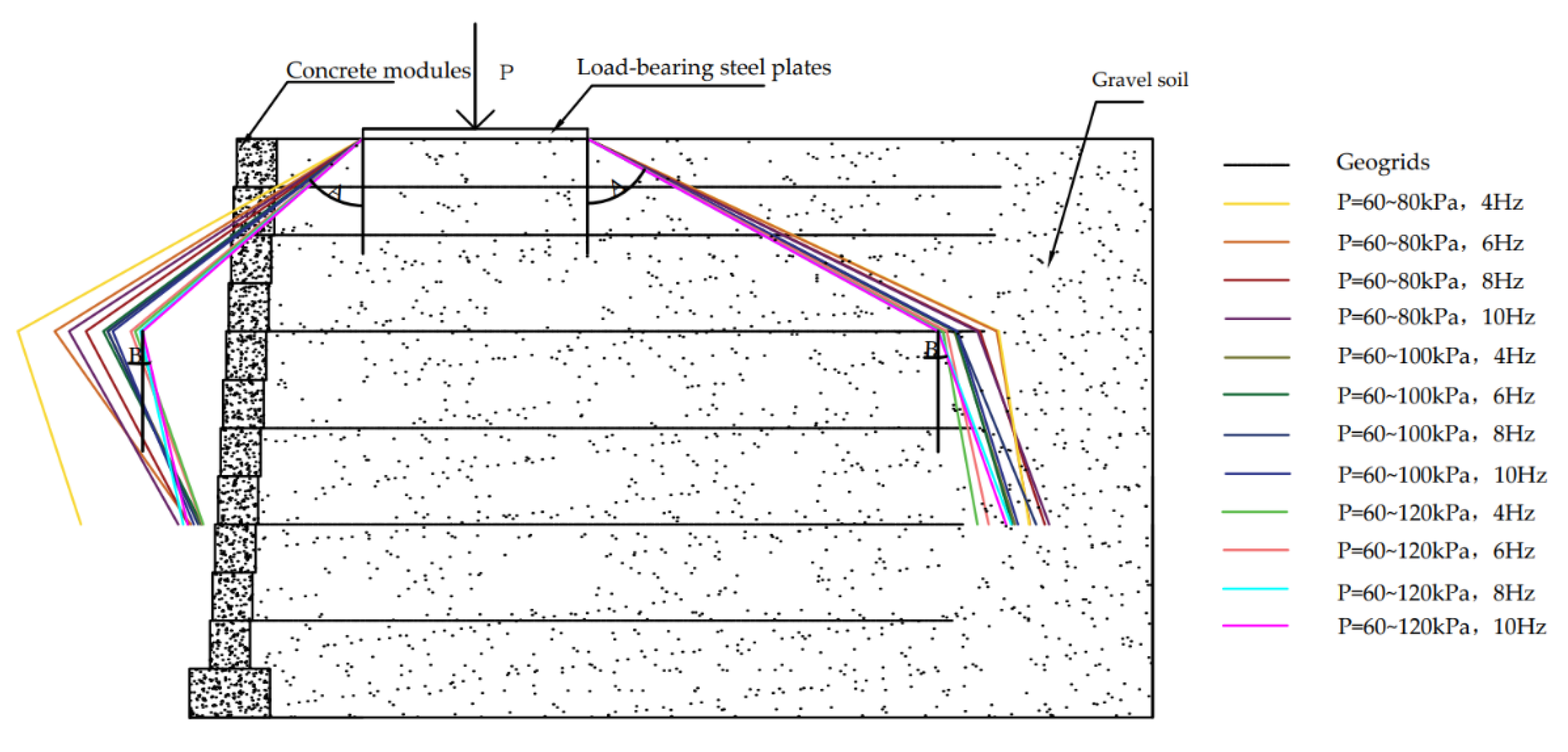
The stress diffusion angle in the reinforced soil retaining walls is the angle between the stress diffusion edge line and the vertical direction line in the soil caused by the external load. In the test, it was difficult to measure the location of zero stress, so to determine this location, barycentric interpolation of the triangle according to the measured values was used to obtain the coordinates, and then the stress diffusion edge line was obtained by connecting the lines and calculating the angle between the edge line and the vertical direction line to obtain the stress diffusion angle of the retaining wall.
The principle of the triangle barycenter coordinate interpolation is based on knowing each of the vertex coordinates and the stress value of the triangle, as shown in Figure 7. The influence of each vertex on the weight of a point inside the triangle was calculated by Equations (1)–(3), so as to obtain the coordinates and stress value of a point inside the triangle. This paper assumed that the additional stress zero point was known, so the coordinate of the additional stress zero point could be obtained by the trial algorithm. The stress diffusion angle is shown in Table 5 and the stress diffusion line is shown in Figure 8.
where: 1 − u − v is the weight of point P1, u is the weight of point P2, and v is the weight of point P3.
P = (1 − u − v)*P1 + u*P2 + v*P3
P(x) = (1 − u − v)*P1(x) + u*P2(x) + v*P3(x)
P(y) = (1 − u − v)*P1(y) + u*P2(y) + v*P3(y)
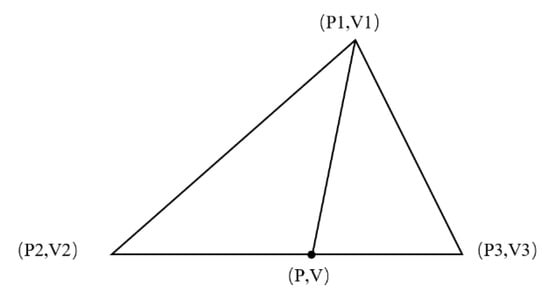
Figure 7.
Triangle barycentric interpolation diagram.
Table 5.
Additional stress diffusion angle of the reinforced soil retaining wall.
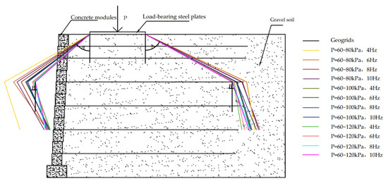
Figure 8.
Diagram of the measured stress diffusion line in the reinforced soil retaining wall.
The diffusion angle of the stress caused by the external load of the reinforced body was basically between 50° and 65° in the range from 1.8 m to 1.2 m, which was larger than that of the unreinforced body (generally 30°); as the stress caused by the external load gradually decayed in the soil, the diffusion angle gradually became smaller from high to low along the wall height, so the stress diffusion angle was smaller in the range from 1.2 m to 0.6 m of the wall height. The analysis of the data in the table showed that:
- There was a maximum stress diffusion angle within the reinforced body; the diffusion angle at the top was slightly larger than the diffusion angle in the middle.
- The stress diffusion angle within the reinforced soil caused by the external load on the side of the retaining wall close to the panel was smaller than that on the side away from the panel.
- The stress diffusion angle A decreased with the increase in dynamic stress amplitude, while diffusion angle B had no obvious pattern.
- The stress diffusion angles A and B had no obvious pattern with the increase in frequency.
- The diffusion angle at the top reaches its maximum value when the loading amplitude was 60–80kPa and the dynamic stress frequency was 4 Hz, while there was no obvious pattern in the middle.
4. Numerical Simulation
4.1. Model Material Parameters
A finite element model of the reinforced soil retaining wall was established according to the laboratory model tests by PLAXIS 8.5, the material parameters of the geogrids and the filler and concrete modules of the wall are shown in Table 6 and Table 7. The strength of the geogrid may strongly affect the wall behavior under cyclic loading.
Table 6.
Geogrid parameters.
Table 7.
Material parameters for the filler and wall concrete modules.
4.2. Model Building
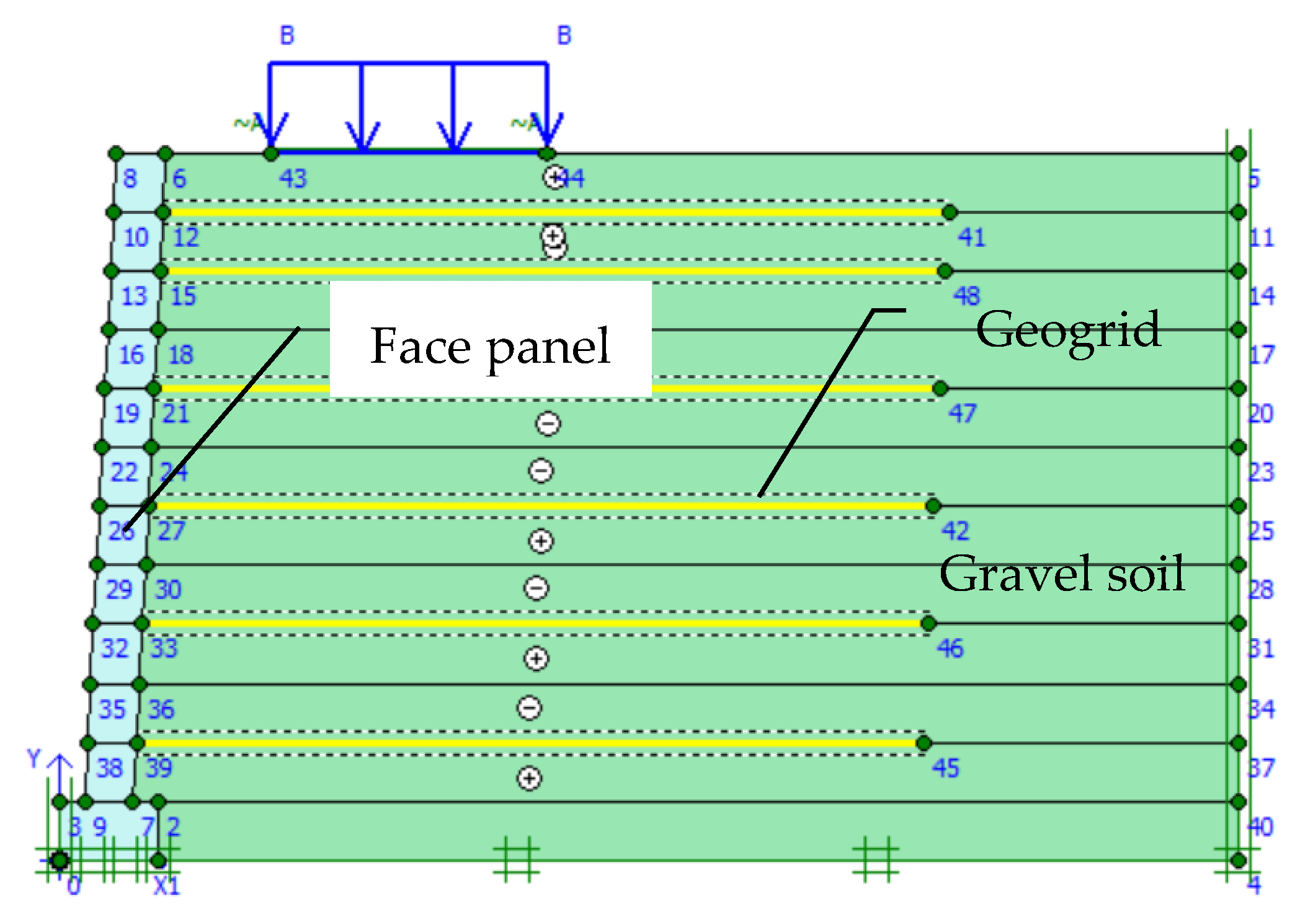
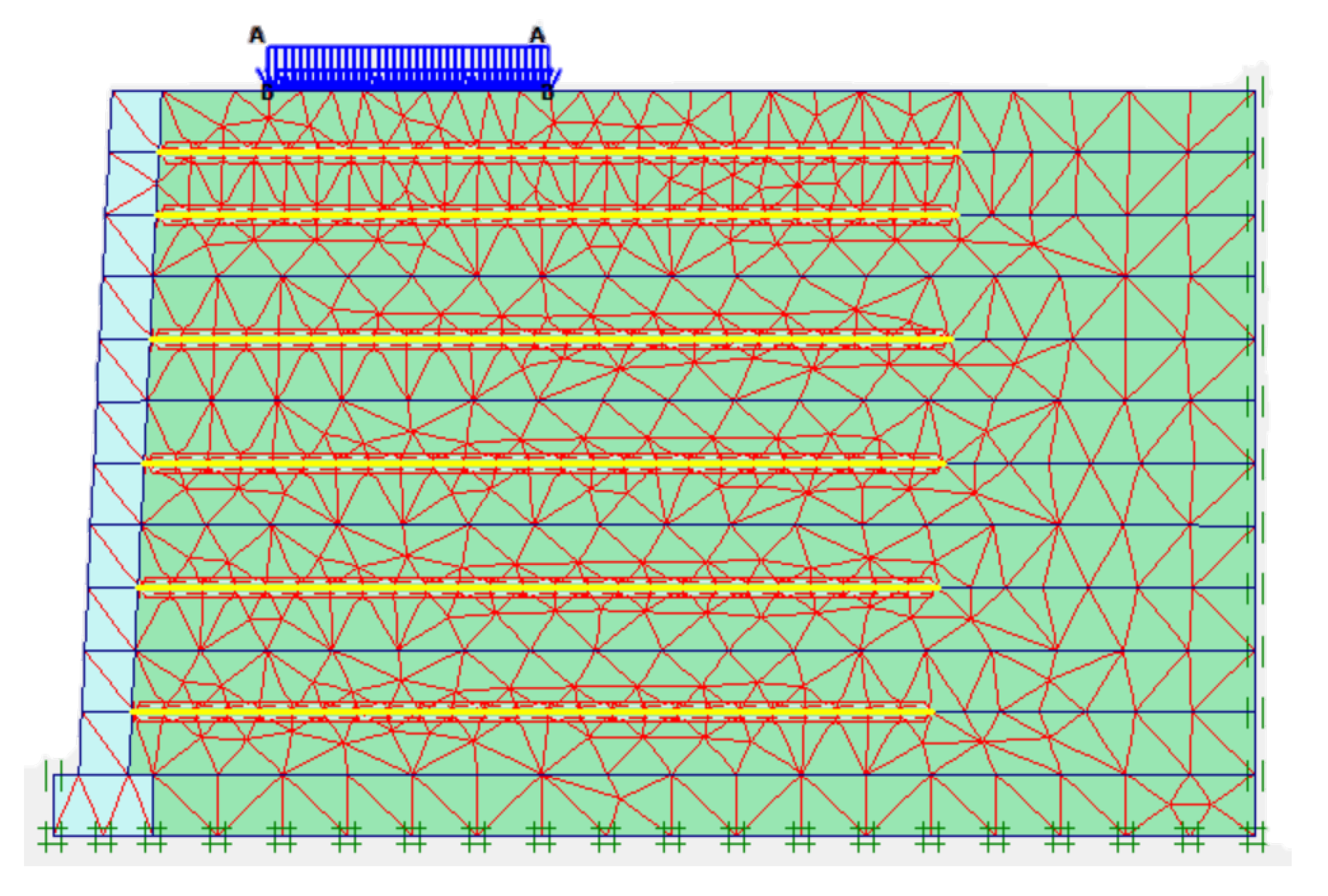
Considering the influence of reinforcement–soil interactions, the contact surface of the reinforcement and soil was defined by the interface unit, and the reinforcement–soil interface friction coefficient Rinter was used to reflect the degree of the reinforcement–soil interaction. According to the PLAXIS Reference Manual, the Rinter is calculated by Equation (4), for the actual soil–structure interaction, the interface has a lower strength than the adjacent soil layer, so Rinter is less than 1, which can be assumed to be 0.67 in general. Therefore, Rinter in this model was set as 0.67. The boundary conditions were horizontal constraints on both sides and horizontal and vertical constraints at the bottom of the foundation. The numerical analysis model of the reinforced soil retaining wall is shown in Figure 9. The diagram of the generated meshes is shown in Figure 10; a total of 889 meshes were generated.
where: φi is interface internal friction angle and φsoil is internal friction angle of soil
tanφi = Rintertanφsoil
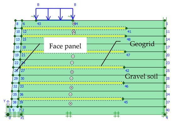
Figure 9.
Diagram of the numerical analysis model.
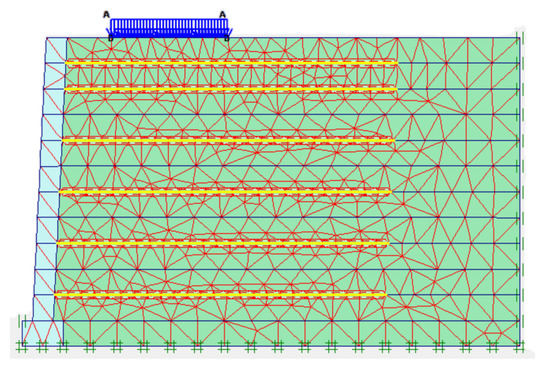
Figure 10.
Diagram of the generated meshes.
The numerical simulation results were compared with the measured values of the model test and, as seen in Figure 11, the simulated values were similar to the measured values. The slight difference in values was due to uneven packing in the actual engineering, whereas the packing was uniform in the PLAXIS model. This proves that the numerical model parameters were reasonable.
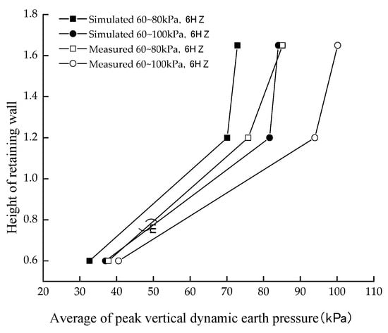
Figure 11.
Diagram of the comparison of the peak vertical dynamic earth pressure at the loading position.
4.3. Influencing Factors of the Stress Diffusion Angle
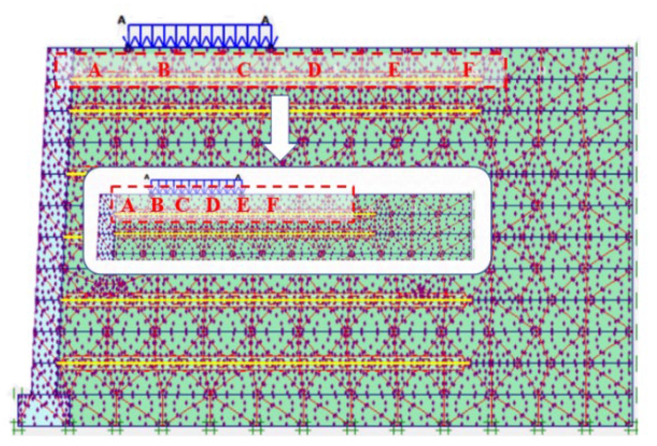
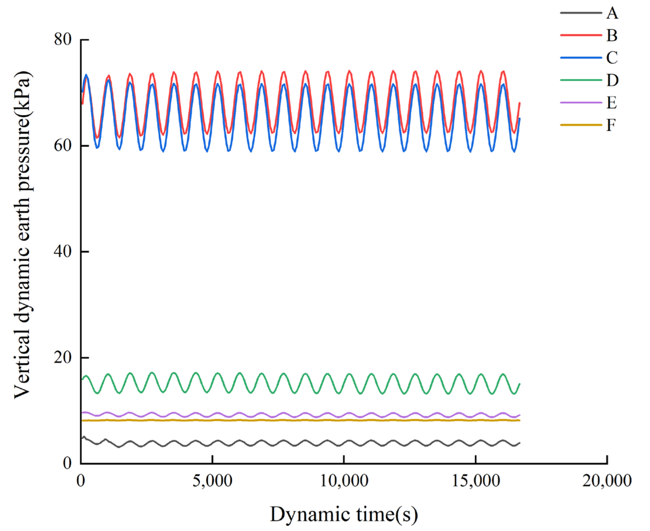
It was difficult to obtain the diffusion cloud map of additional stress in the numerical simulation, however the vertical stress fluctuation amplitude of each stress point in the retaining wall under a cyclic load at different heights was used to determine the position of stress zero. We used the wall height of 1.65 m as an example and selected the stress point model, as shown in Figure 12, and the output of each point time–stress curve, as shown in Figure 13. When the vertical stress curve fluctuations are relatively small, this stress point is less affected by the top load. When the wave amplitude is small enough to ignore, the additional pressure will be almost zero and the stress at this point will be zero. According to the above method, we analyzed the vertical stress amplitude of each stress point under different retaining wall heights, the additional stress zero point was found by reducing the stress point range, and then the stress zero point was connected to obtain the stress diffusion line.
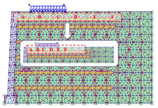
Figure 12.
The stress point at 1.65 m wall height.
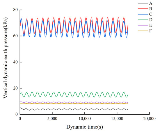
Figure 13.
The time–stress curve for each point.
In the finite element analysis of reinforced soil retaining walls, the stress diffusion characteristics of the wall were analyzed by varying the tensile modulus of reinforcement, dynamic stress frequency, reinforcement spacing, dynamic stress amplitude, and the reinforcement–soil interaction coefficient, to obtain the influence law of the stress diffusion characteristics of reinforced soil retaining walls.
4.3.1. Influence of the Tensile Modulus of Reinforcement
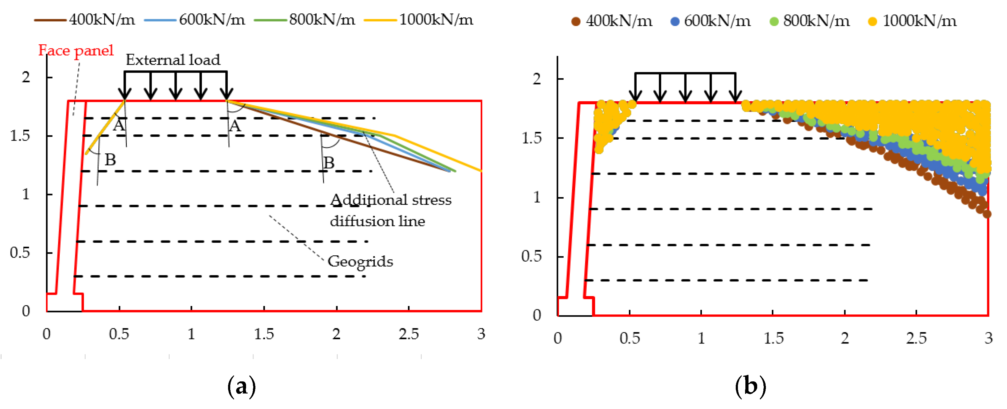
In the analysis of the influence of the tensile modulus of the reinforcement on the stress diffusion angle caused by the external load of RSW under a dynamic load, the other parameters were kept constant and the tensile modulus of the reinforcement material was changed alone to analyze the change in the stress diffusion angle. The four working conditions were 400 kN/m, 600 kN/m, 800 kN/m, and 1000 kN/m. The stress diffusion in the RSW caused by external loads under different working conditions is shown in Figure 14 and the stress diffusion angles are shown in Table 8.

Figure 14.
Stress diffusion in reinforced soil retaining walls with different tensile modula of the reinforcement: (a) stress diffusion line in reinforced soil retaining walls with different tensile modulus of the reinforcement; (b) stress diffusion point in reinforced soil retaining walls with different tensile modulus of the reinforcement.
Table 8.
Stress diffusion angle in reinforced soil retaining walls with different tensile modulus of the reinforcement.
The analysis of the numerical simulation results showed that the change in the stress diffusion angle close to the panel was not obvious with the increase in the tensile modulus of the reinforcement. The stress diffusion angle away from the panel increased with the increase in the tensile modulus of the reinforcement, probably due to the lateral displacement of the retaining wall under the horizontal earth pressure, resulting in the release of the stress, meaning the change in the stress diffusion angle close to the panel is not obvious. As the tensile modulus of the reinforcement increased, it limited the transfer of acceleration along the contact surface to the roadbed, reducing the range of the roadbed affected by acceleration; when the dynamic load was applied, the occlusal force between the reinforcement and the soil restrained and limited the displacement of the soil, which can improve the reinforcing effect of the reinforcement to a certain extent, so the stress diffusion range was expanded.
4.3.2. Influence of Dynamic Stress Frequency
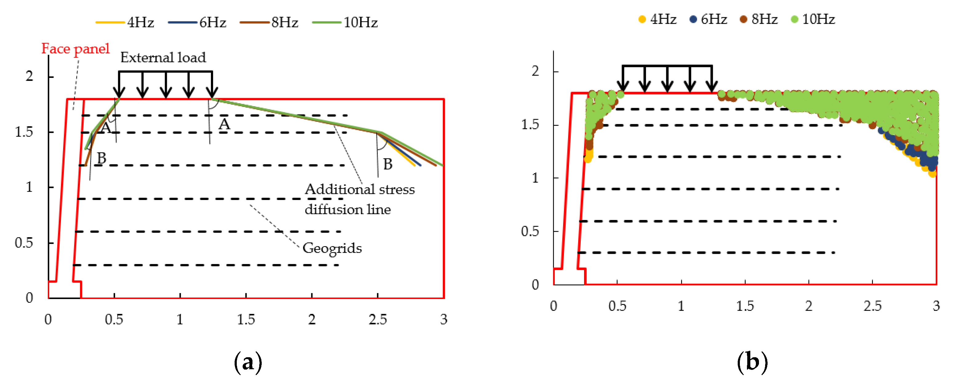
In the analysis of the effect of dynamic stress frequency on the stress diffusion angle caused by the external load in reinforced soil retaining walls under dynamic loads, the other parameters were kept constant and the dynamic stress frequency was changed alone. The four working conditions with dynamic stress frequencies were 4 Hz, 6 Hz, 8 Hz, and 10 Hz. The stress diffusion in the RSW caused by external loads under different working conditions is shown in Figure 15 and the stress diffusion angles are shown in Table 9.

Figure 15.
Stress diffusion in reinforced soil retaining walls with different dynamic stress frequencies; (a) stress diffusion line in reinforced soil retaining walls with different dynamic stress frequencies; (b) stress diffusion point in reinforced soil retaining walls with different dynamic stress frequencies.
Table 9.
Stress diffusion angle in reinforced soil retaining walls with different dynamic stress frequencies.
The analysis of the numerical simulation results showed that:
- With the increase in loading frequency, the stress diffusion angle near the wall panel did not change.
- The stress diffusion angle away from the wall panel increased gradually and the increase in the stress diffusion angle away from the wall panel was greater than that near the wall panel.
This was due to the increased frequency of dynamic stresses and good soil compaction, which increased the interaction between the soil and the reinforcement, while there were fewer geogrids in the upper part of the retaining wall, so there was no significant change in the diffusion angle A. The diffusion angle of the stress on the side near the wall did not change in the dynamic stress frequency, this is due to the lateral displacement of the retaining wall under the action of horizontal earth pressure, resulting in stress release, so the change in frequency had no significant effect on the diffusion angle on the side near the panel.
4.3.3. Influence of Reinforcement Spacing
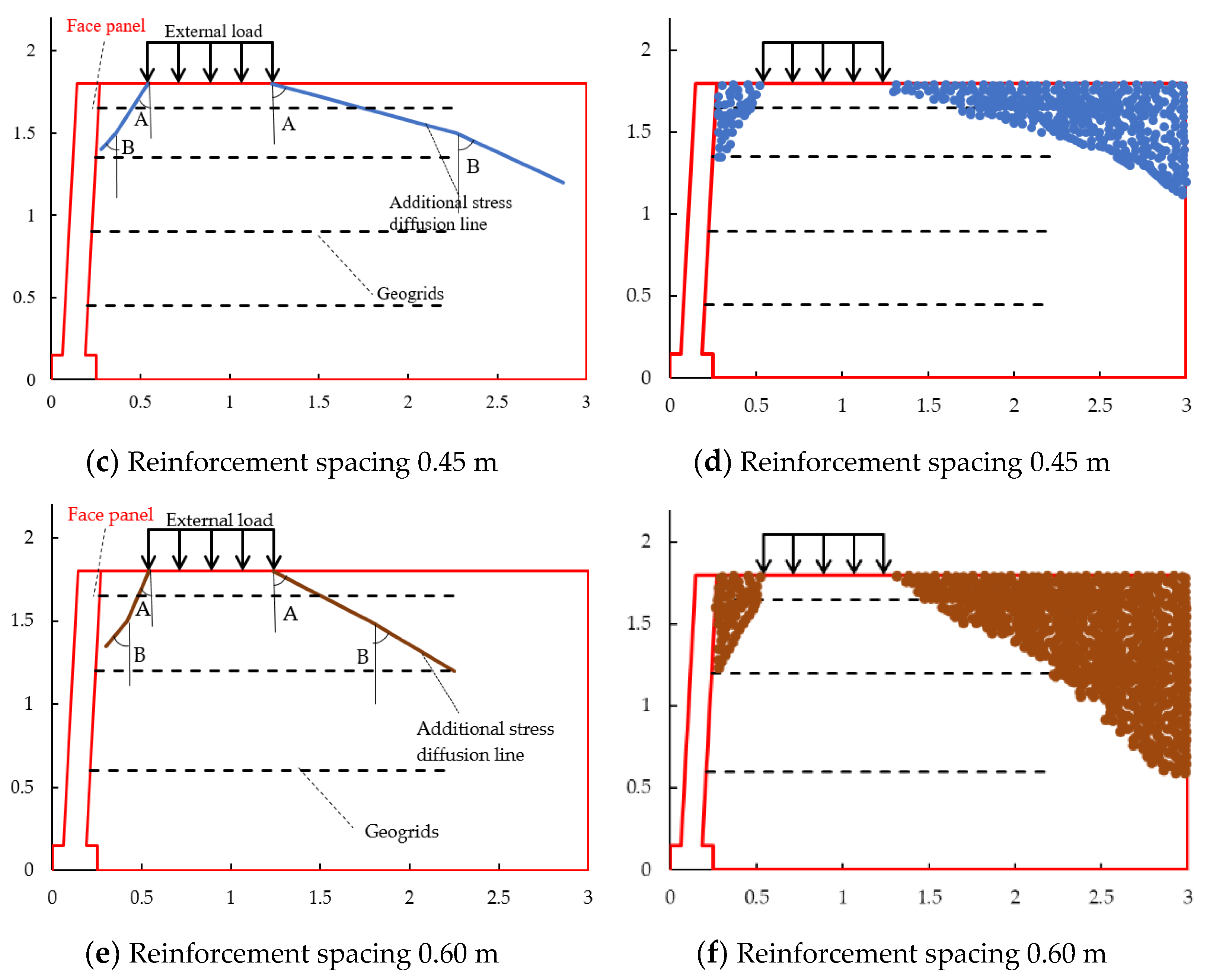
In the analysis of the influence of the reinforcement spacing on the stress diffusion angle under a dynamic load, the other parameters were kept constant and the reinforcement spacing was changed individually. The reinforcement spacings were 0.30 m, 0.45 m, and 0.60 m. The stress diffusion in the RSW caused by external loads under different working conditions are shown in Figure 16 and the stress diffusion angles are shown in Table 10.
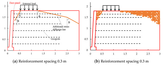
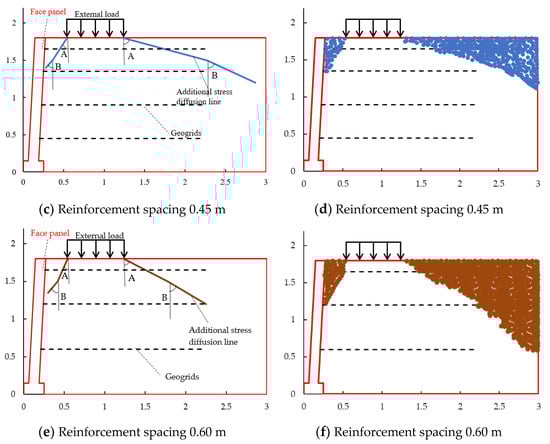
Figure 16.
Stress diffusion in reinforced soil retaining walls with different reinforcement spacings; (a,c,e) stress diffusion line in reinforced soil retaining walls with different reinforcement spacings; (b,d,f) stress diffusion point in reinforced soil retaining walls with different reinforcement spacings.
Table 10.
Stress diffusion angle in reinforced soil retaining walls with different reinforcement spacing.
The analysis of the numerical simulation results showed that:
- Diffusion angle A decreases with the increase in reinforcement spacing and diffusion angle B increases with the increase in reinforcement spacing.
- Near the panel, the stress diffusion range shows a trend of outward diffusion with the decrease in the retaining wall height, while away from the panel, the stress diffusion range shows a trend of inward contraction with the decrease in the retaining wall height.
This was because the interaction between the soil and the reinforcement decreased as the reinforcement spacing increased, the soil structure of the retaining wall decreased and the range of the soil involved in the bearing decreased, and then the diffusion range decreases. With the decrease in the distance between the reinforcements, the increase range decrease indicated that the dense reinforcement is not better.
4.3.4. Influence of the Reinforcement–Soil Interaction
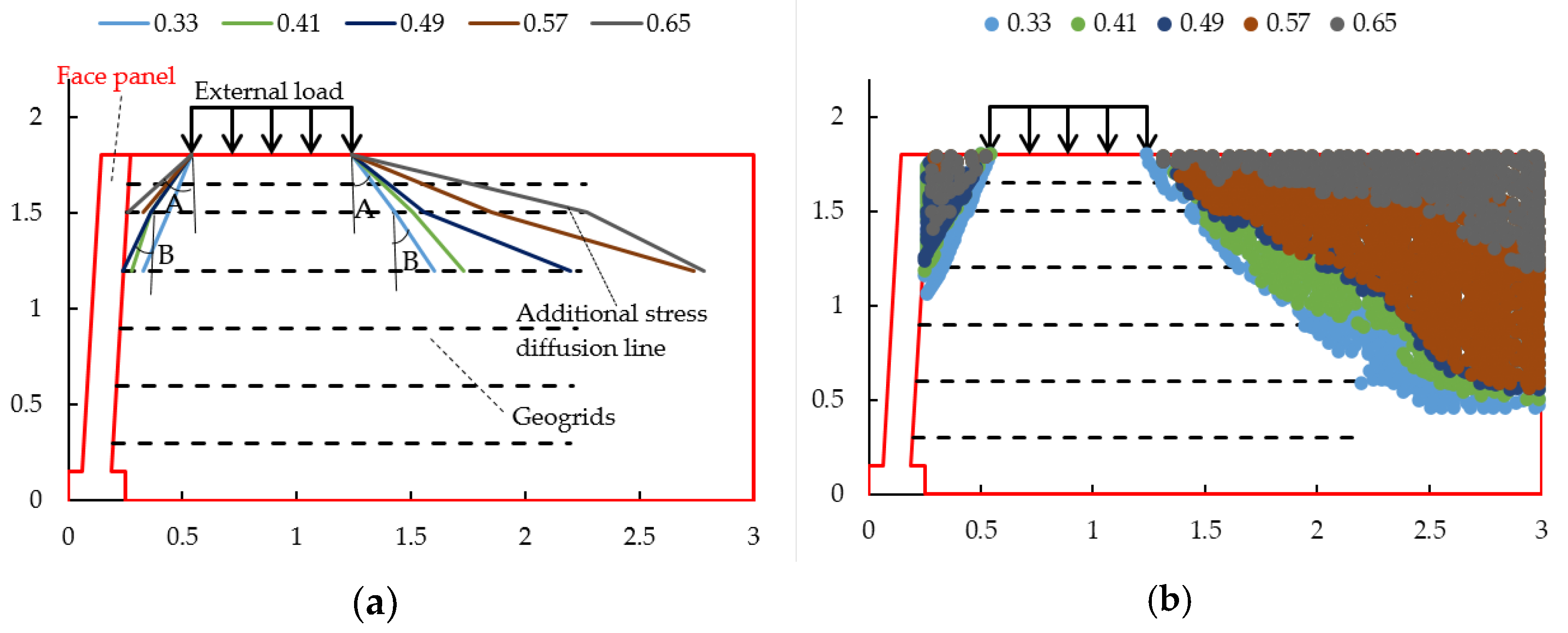
In the analysis of the effect of reinforced soil interaction on the stress diffusion angle under a dynamic load, the other parameters were kept constant and the coefficient of the reinforced soil interaction was changed alone. The coefficient of the reinforcement–soil interface was selected to be 0.33, 0.41, 0.49, 0.57, and 0.65, respectively, for the five working conditions. The stress diffusion caused by external loads in the reinforced soil retaining wall under different working conditions are shown in Figure 17 and the stress diffusion angles are shown in Table 11.
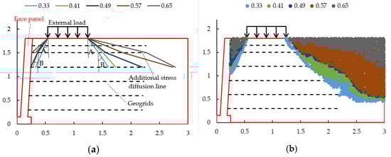
Figure 17.
Stress diffusion in reinforced soil retaining walls with different coefficients of reinforcement–soil values; (a) stress diffusion line in reinforced soil retaining walls with different coefficients of reinforcement–soil values; (b) stress diffusion point in reinforced soil retaining walls with different coefficients of reinforcement–soil values.
Table 11.
Stress diffusion angle in reinforced soil retaining walls with different coefficient of reinforcement–soil values.
The analysis of the numerical simulation results showed that:
- The stress diffusion angle A increased with the increased coefficient of the reinforcement–soil. Although the diffusion angle B had a little bit of a decreased trend, the diffusion range still showed an increasing trend.
- With the increase in the interaction coefficient of the reinforcement–soil, the average increased for the stress diffusion Angle A near the wall was 25.99% and that away from the wall was 23.22%, indicating that the stress diffusion angle near the wall was more sensitive to the change in the interaction coefficient of the reinforcement–soil.
This was because the reinforcement effect is enhanced and the stress diffusion range was large due to the increase in the coefficient of the reinforcement–soil, which increases the friction and occlusion between the reinforcement and the soil.
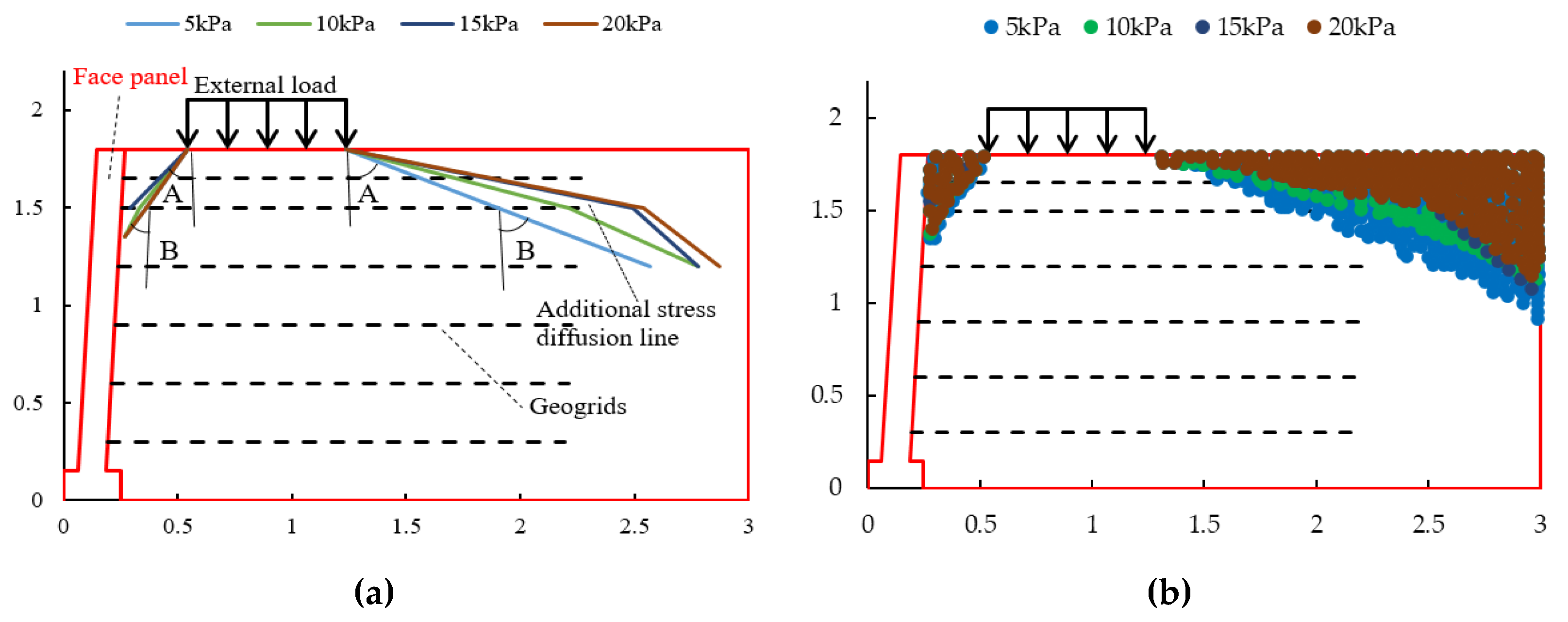
4.3.5. Influence of Dynamic Stress Amplitude
In the analysis of the effect of different dynamic stress amplitudes on the stress diffusion angle under a dynamic load, the other parameters were kept constant and the dynamic stress amplitude was changed individually; the four working conditions with dynamic stress amplitudes were 5 kPa, 10 kPa, 15 kPa, and 20 kPa. The stress diffusion caused by the external load in the reinforced soil retaining wall under different working conditions is shown in Figure 18 and the stress diffusion angle is shown in Table 12.
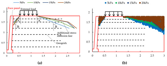
Figure 18.
Stress diffusion in reinforced soil retaining walls with different dynamic stress amplitudes; (a) stress diffusion line in reinforced soil retaining walls with different dynamic stress amplitudes; (b) stress diffusion point in reinforced soil retaining walls with different dynamic stress amplitudes.
Table 12.
Stress diffusion angle in reinforced soil retaining walls with different dynamic stress amplitudes.
The analysis of the numerical simulation results showed that:
- The stress diffusion for angle A on the side close to the panel increased with the increase in the dynamic stress amplitude and, when the dynamic stress amplitude reached 20 kPa, the diffusion angle A tended to decrease; the diffusion angle B had no obvious regular change.
- The stress diffusion for angle A on the side away from the panel increased with the increase in the dynamic stress amplitude and the diffusion angle B decreased with the increase in the dynamic stress amplitude, but the diffusion range still tended to expand.
This was because, with the increase in the dynamic stress amplitude, the compactness of the soil increased, the interaction between the reinforcement and the soil increased, and the bearing range of the soil increased, so the stress diffusion angle increased. When the stress reached 20 kPa, the retaining wall produced lateral displacement, resulting in stress release, so the stress diffusion angle decreased.
5. Discussion
At present, through the field test and theoretical analysis, a significant amount of research exists on the law of train load transfer in high-speed railway subgrades. However, there are few studies on the transfer of train loads in reinforced subgrade and retaining walls. In this paper, the influencing factors of the stress diffusion angle were obtained through experiments and numerical simulations, which is of great significance to the design of retaining walls and the foundation bed structure.
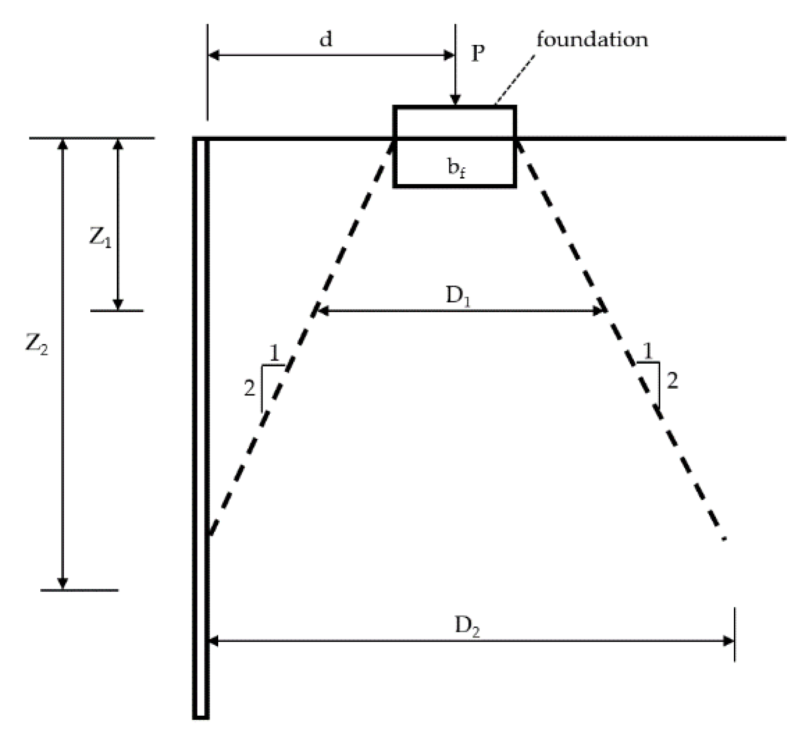
According to the calculation method of vertical additional stress in FHWA—the calculation formula is shown in (5) and the calculation diagram is shown in Figure 19—the vertical additional stress decreased with the increase in the stress diffusion angle.

Figure 19.
Calculation diagram of vertical additional stress.
In the design specification of the reinforced earth retaining walls, the stress diffusion is calculated according to 1:2 and the stress diffusion angle obtained in this study is greater than the standard value.
However, this study still has some limitations. There is no physical engineering field test in this study, so the next step should be further studied in a field test.
6. Conclusions
In this study, the stress diffusion characteristics of reinforced soil retaining walls under dynamic loading were investigated using model tests and numerical simulations and the following conclusions were obtained.
- The mean value of the vertical dynamic earth pressure caused by the external load was non-linearly distributed with the height of the retaining wall, decaying from top to bottom. The decay rate at the top was 14.9% smaller than that at the bottom, which was 58.54%, and increased with the increase in the loading amplitude, while the loading frequency and number of loading cycles had no obvious effect on the mean value of the vertical dynamic earth pressure caused by the external load.
- The diffusion angle of the stress caused by the external load of the reinforced body was basically between 50° and 65° in the range from 1.8 m to 1.2 m. The diffusion angle at the top of the retaining wall was slightly larger than that at the middle; the stress diffusion angle at the side near the panel was smaller than that at the side away from the panel. The stress diffusion angle increased with the increase in the loading amplitude and had no obvious change with the increase in the loading frequency. The rule was consistent with the numerical simulation results. The stress diffusion angle reaches the maximum value at the loading amplitude of 60–80kPa and dynamic stress frequency of 4 Hz.
- The stress diffusion range of the reinforced soil retaining wall increased with the increase in the coefficient of the reinforcement—soil, dynamic stress amplitude, dynamic stress frequency, and tensile modulus of the reinforcement material; it decreased with an increase in the reinforcement spacing.
- With the change in the coefficient of reinforcement–soil, dynamic stress amplitude, dynamic stress frequency, tensile modulus of reinforcement, and the spacing of reinforcement. The average variation amplitude of stress diffusion angle A was 24.6%, 12.02%, 0.52%, 1.83%, and 5.61%, respectively. The main factors affecting the stress diffusion in reinforced soil retaining walls were the coefficient of reinforcement–soil and the dynamic stress amplitude. The second factor was the tensile modulus of the reinforcement and the dynamic stress frequency, with the reinforcement spacing having less influence. The change in the stress diffusion was more obvious with the change in parameters on the side away from the panel than on the side near the panel.
Author Contributions
Writing‒original draft preparation, H.W.; writing‒review and editing, N.W.; validation, G.Y. and J.M. All authors have read and agreed to the published version of the manuscript.
Funding
This research was supported by the National Key Research and Development Program of China (No. 2022YFE0104600), the National Natural Science Foundation of China (No. 52079078), and the Key Research and Development Plan of Hebei Province (No. 20375504D).
Institutional Review Board Statement
Not applicable.
Informed Consent Statement
Not applicable.
Data Availability Statement
The data used to support the findings of this study are available from the corresponding author upon request.
Conflicts of Interest
The authors declare no conflict of interest.
References
- Wang, H.; Yang, G.Q.; Xiong, B.L. An experimental study of the structural behavior of reinforced soil retaining wall with concrete-block panel. Rock Soil Mech. 2016, 37, 487–498. [Google Scholar]
- Wu, L.H.; Yang, G.Q.; Zhang, Q.B. In-situ test on dynamic responses of reinforced soil retaining walls for high-speed railways. J. Southwest Jiaotong Univ. 2017, 52, 546–553. [Google Scholar]
- Pham, H.V.; Dias, D.; Dudchenko, A. 3D modeling of geosynthetic-reinforced pile-supported embankment under cyclic loading. Geosynth. Int. 2018, 27, 157–169. [Google Scholar] [CrossRef]
- Aqoub, K.; Mohamed, M.; Sheehan, T. Analysis of unreinforced and reinforced shallow piled embankments under cyclic loading. Geosynth. Int. 2019, 27, 182–199. [Google Scholar] [CrossRef]
- Aqoub, K.; Mohamed, M.; Sheehan, T. Quantitative analysis of shallow unreinforced and reinforced piled embankments with different heights subject to cyclic loads: Experimental study. Soil Dyn. Earthq. Eng. 2020, 138, 106277. [Google Scholar] [CrossRef]
- Wang, J.Q.; Xu, L.J.; Li, Y.Y. Influence of dynamic loading frequency on dynamic characteristics of geogrid reinforced soil retaining walls. J. Vib. Eng. 2019, 32, 898–907. [Google Scholar]
- Wang, J.Q.; Xu, L.J.; Huang, S.B. Analysis of bearing behavior of geogrid reinforced abutment retaining wall under dynamic load. Rock Soil Mech. 2019, 40, 4220–4228+4269. [Google Scholar]
- Wang, J.Q.; Xu, L.J.; Xue, J.F. Laboratory study on geogrid reinforced soil wall with modular facing under cyclic strip loading. Arab. J. Geosci. 2020, 13, 70–83. [Google Scholar] [CrossRef]
- Xiao, C.Z.; Gao, S.; Li, H.Q. Experimental study on performance of multi-tiered geogrid reinforced soil retaining wall under uniform static load. J. Eng. Geol. 2020, 28, 1359–1367. [Google Scholar]
- Fattah Mohammed, Y.; Salim Nahla, M.; Ismaiel Mohammad, S. Influence of Geogrid Reinforcement of Sand in Transfer of Dynamic Loading to Underground Structure. Earth Environ. Sci. 2021, 856, 012013. [Google Scholar]
- Kargar, M.; Mir Mohammad Hosseini, S.M. Earth pressure distribution behind rigid non-yielding walls under the effect of repeated loading on backfill. Arab. J. Geosci. 2015, 8, 839–847. [Google Scholar] [CrossRef]
- Ding, G.Y.; Wu, J.L.; Wang, J. Experimental study on vibration reduction by using soilbag cushions under traffic loads. Geosynth. Int. 2018, 25, 322–333. [Google Scholar] [CrossRef]
- Luo, X.W.; Lu, Z.; Yao, H.L. Experimental study on soft rock subgrade reinforced with geocell. Road Mater. Pavement Des. 2022, 23, 2190–2204. [Google Scholar] [CrossRef]
- Zhang, T. Study on dynamic characteristics of subgrade filler under vehicle load. Water Sci. Eng. 2022, 2, 78–82. [Google Scholar]


Publisher’s Note: MDPI stays neutral with regard to jurisdictional claims in published maps and institutional affiliations. |
© 2022 by the authors. Licensee MDPI, Basel, Switzerland. This article is an open access article distributed under the terms and conditions of the Creative Commons Attribution (CC BY) license (https://creativecommons.org/licenses/by/4.0/).