Article

Effect of Fluid Contact Angle of Oil-Wet Fracture Proppant on the Competing Water/Oil Flow in Sandstone-Proppant Systems

Department of Petroleum Engineering, University of Louisiana at Lafayette, Lafayette, LA 70504, USA
*
Author to whom correspondence should be addressed.
Sustainability 2022, 14(7), 3766; https://doi.org/10.3390/su14073766
Submission received: 7 February 2022 / Revised: 9 March 2022 / Accepted: 19 March 2022 / Published: 23 March 2022
(This article belongs to the Section Energy Sustainability)

Abstract

:
Ceramic fracture proppants are extensively used for enhancing the recovery of fossil energy and geothermal energy. Previous work has reported the attracting-oil-repelling-water (AORW) property of oil-wet proppants at the faces of fractures. Because of the lack of a method for measuring the contact angle of proppant packs, the terms water-wet proppant and oil-wet proppant were defined based on observations of liquid droplets on the surfaces of proppant packs without quantitative measurement. An innovative method was developed in this study to determine the contact angles of fracture proppant packs. The effect of the oil contact angle of the oil-wet fracture proppant pack on the competing water/oil flow from sandstone cores to the packs was investigated. It was found that, for a given fracture proppant pack, the sum of the water contact angle and oil contact angle measured in the liquid–air–solid systems is less than 180°, i.e., the two angles are not supplementary. This is believed to be due to the weak wetting capacity of air to the solid surfaces in the liquid–air–solid systems. Both water and oil contact angles should be considered in the classification of wettability of proppant packs. Fracture proppant packs with water contact angles greater than 90° and oil contact angles significantly less than 90° can be considered as oil-wet proppants. Reducing oil contact angles of oil-wet proppants can increase capillary force, promote oil imbibition into the proppant packs, and thus improve the AORW performance of proppants. Fracture proppant packs with water contact angles less than 90° and oil contact angles less than 90° may be considered as mixed-wet proppants. Their AORW performance should be tested in laboratories before they are considered for well fracturing operations.

1. Introduction

Hydraulic fracturing is a technology widely used for enhancing oil and gas recovery from petroleum reservoirs and sustaining geothermal energy recovery from hot dry rocks. Hydraulic fractures are the main channels for oil and gas production from low-permeability oil and gas reservoirs. The effects of fracture proppant properties on oil and gas well productivity and hydrocarbon recovery were studied by several investigators including Mao et al. [1], Longoria et al. [2], and Le et al. [3]. Some fracture and proppant parameters in fracturing oil and gas wells have been thoroughly studied [4]. Zhang et al. [5] and Zhu et al. [6] revealed some insights for understanding the mechanical behavior of proppants in hydraulic fractures. He and Senetakis [7] carried out a micromechanical study of shale rock–proppant composite interface. Their result shows that sand grain type and surface roughness of shale affected the contact stiffness in the normal and tangential. The coefficient of friction, the initial tangential stiffness, and the microslip displacement were positively correlated with the magnitude of normal load to the fracture. Although clear surface damage of the shale surface caused by shearing was observed and captured by interferometry images, the effect of the loading history was found to be minimal. Shearing tests on wet and dry shale surfaces did not show a significant difference in results, but the immersion of shale in the water prior to shearing affected the initial tangential stiffness and coefficient of friction at certain normal loads. Smoothening of the surface had an influence on friction as long as limited plowing was triggered in the low range of normal loads, so that the influence of surface roughness of the shale would diminish at higher normal loads where the plowing mechanism dominated the interface. Mehmood et al. [8] investigated using rod-shaped proppants for improved recovery in tight gas reservoirs by reducing proppant embedment into the shale rock. Apart from the in situ stresses, the producing bottom hole pressure contributes to fracture aperture reduction. The aspect ratio of the proppant was found to potentially affect fracture conductivity. The rod-shaped proppant with an aspect ratio of 3 can be a better choice for the case studied. Recently, Shaibu et al. [9] published a study on the stress-sensitivity of fracture conductivity of Tuscaloosa Marine Shale cores. They found that fracture conductivity declined exponentially with confinement pressure. The time-dependent decline in conductivity shows two decline trends, which are likely caused by (a) decline from a reduction in main fracture width and (b) decline from the healing of developed microcracks. Reduction in fracture width is most probably controlled by proppant embedment due to softening of the fracture face by the swelling of clay minerals. Microcracks developed and possibly closed in the cores during the experiments. A moderate effect of elastic mechanical properties on fracture conductivity was realized at confinement pressures of 10.34 MPa and above. Young’s modulus showed a positive correlation with fracture conductivity, whereas Poisson’s ratio showed an inverse relationship. There was no observed correlation between rock mineralogy and fracture conductivity.
In the enhanced geothermal systems (EGS), hydraulic fractures are the main channels for geothermal exploitation from hot dry rocks. Due to the in situ stress and chemical effects, fracture closes and its permeability declines. Hydraulic fracturing proppant treatment is effective to decrease the fracture closing and maintain fluid circulation in geothermal production. Zhang and Wu [10] recently performed an experimental study on the evolution of permeability and heat recovery efficiency in fractured granite with proppants. They found that both permeability and heat recovery efficiency of samples decreased with the increase in rock temperature and confining pressure. The addition of proppants could effectively reduce the negative influence. Their further analysis reveals that the pressure dissolution and water weakening effects on fractures were responsible for the decrease in permeability and net heat extraction rate in EGS.
Dong [11] conducted tests in small scale, focusing on the interface between sandstone and proppant packs to study the effect of surface wettability of ceramic proppant on the oil flow efficiency from core samples to fractures filled with CC (code for proppant provider) proppants. He observed that oil-wet proppant increased oil flow efficiency from sandstone to proppant packs. The mechanism is interpreted as the oil imbibition-induced oil flow channels across the sand–fracture interface. That is, oil-wet proppants have a common property of attracting-oil-repelling-water (AORW) at the interface between sandstone and proppant pack. Dong et al. [12] further investigated the effect of the wettability of the CC proppant surface in guar gum solution on the oil flow efficiency in fractures. They concluded that the residual guar gum in the fractures has a negative effect on improving oil-flow efficiency. Dong et al. [13] investigated the effects of oil-wet and mixed-wet surfaces of ceramic proppants on the oil flow using SEM and energy-dispersive systems and found that the resin-coated oil-wet proppant surface is much smoother than that of the mixed-wet proppant. Based on the result of oxide analysis, there is a layer of oleophilic materials, which causes the oil affinity of the oil-wet proppants. However, the mixed-wet proppant presents a dual affinity of oil and water due to capillary cohesion. They also concluded that the surface wettability plays a more essential role in determining the competing flow of oil and water in small-size proppants than in large-size proppants. As the proppant size increases, the effect of surface wettability on hydrogen transfer diminishes. Xiao et al. [14] investigated the AORW property of PC (code for proppant provider) proppants and verified Dong’s [11] work.
However, in all the work of Dong [11,12,13] and Xiao et al. [14], the terms water-wet proppant and oil-wet proppant were defined based on observations of liquid droplets on the surfaces of proppant packs without quantitative measurement. It is highly desirable to quantify the wettability of proppant packs using a measurable parameter so that the AORW behavior of proppants can be better described.
Solid surface wetting behavior is characterized by the level of hydrophobicity and hydrophilicity based on contact angle. Washburn [15] developed a relationship between contact angle and capillary flow rate. Dove et al. [16] measured the contact angle between water and caffeine particles by using the glass slide method, compacted plate method, and the inverse gas chromatography (IGC) method. Awasthi et al. [17] proposed an optical method to measure the contact angle between mercury and graphite at room temperature. Hung et al. [18] proposed a modified selected plane method to find the real contact point and avoid the image distortion effect for calculating the superhydrophobic contact angle based on droplet apex, height, and two interfacial loci. Meiron et al. [19] measured the contact angle of water and ethylene glycol on rough beeswax surfaces using a vertically vibrating method to make the drop reach the lowest energy to calculate the apparent contact angle from drop diameter and weight. Cui et al. [20] measured the contact angle for highly porous silica gel using the thin layer wicking method and found a discrepancy in liquid penetration velocity between the unsaturated and pre-saturated silica. Iliev et al. [21] presented a numerical model to determine the contact angle of non-axisymmetric drops when the contact line of the drop is available. Chini et al. [22] present a sub-pixel polynomial fitting (SPPF) method to measure the contact angle of symmetric and asymmetric drops without using any liquid property value. Liu et al. [23] proposed a new method to investigate fluid dynamic contact angles with less than 1.0 mm capillary length on superomniphobic surfaces. However, none of these methods can be used to measure the contact angles of solid particles and particle packs due to small particle sizes and their non-flat surfaces.
Based on the geometric relation of parameters of liquid droplets at solid surfaces, an analytical method was developed in this work for determining the liquid contact angle measured from the volume and diameter data of droplets. The new method was validated through a comparison of the water contact angles at stainless steel surfaces measured in this work and the literature. The difference between the results is within 3%, indicating the reliability of the new method. Packs of two PC (code of proppant manufacturer for avoiding commercial promotion) proppants were tested with the new method to determine their contact angles of water and oil. The AORW property of these proppant packs was also tested. This work provides a more rigorous means of quantifying the AORW property of fracturing proppants through contact angle measurement.

2. Experimental Design

Sandstone Core Samples. Two sandstone core samples with a permeability contrast of about 6-fold were selected in this study. They are from Parker Berea Satdstone (PB-SS) and Upper Grey Berea Sandstone (UGB-SS). Petrophysical properties of these samples are summarized in Table 1.
Fracture Proppant. The effect of fluid contact angle of proppant pack on the AORW behavior of proppants was investigated using 4 PC proppant samples, namely PC-OW-1 40/80, PC-OW-2 40/80, PC-OW-1 20/40, and PC-OW-2 20/40, as shown in Figure 1. Determination of fluid contact angle on the proppant particle surface is a big challenge due to the small size of the proppant particle and its none-plat surface. Instead of measuring the contact angle of the proppant surface, people measure the contact angle of the surface of the proppant pack. Although several techniques have been tried for the purpose [24,25,26], they were not successful due to the uncertainty/error in the direct reading of the contact angle at the liquid surface/solid joint point in the image of the liquid droplet. Maojil et al. [25] and Al-Boghail [26] used the pendant drop method with a KRÜSS Drop Shape Analyzer DSA100 for contact angle measurements of proppant packs. They found that contact angle measurements using the pendant drop method are challenging on non-wetted and unleveled proppant particles and cannot be measured on wetted proppant particles due to the roundness/sphericity of the particles.
A new method for determining the contact angle of a proppant pack was developed in this study, assuming that the liquid droplet on the surface of a proppant pack takes the shape of a truncated liquid sphere. If the volume of the liquid droplet and the diameter of the wet area of the proppant pack is measured, the contact area can be determined based on a geometric relation. The volume of the droplet (V) can be measured using a pipette (Figure 1) and the diameter (2S) of the wet area can be measured from a calibrated image of the wet area, even though the droplet ban sink into the proppant pack (Figure 2). The height of the droplet need not be known because it is a function of the droplet volume and wet area.
The fluid contact angle can be determined using the following equation (see Appendix A for derivation):
θ = π 2 tan 1 ( S H )
where S is the radius of the wet area and H is the height of the droplet given by
H = 3 ( 4 B 3 + 27 C 2 ) + 9 C 3 18 3 2 3 3 B 3 ( 4 B 3 + 27 C 2 ) + 9 C 3
where
B = 3 S 2
and
C = 6 V π
The new method was validated through a comparison of its result to that found in the literature for a water–air–stainless steel 304 system and a water–air–copper system under ambient conditions. After measuring the volume of over 1000 water droplets, the average volume of the water droplets was determined to be 0.045 cc in our lab at a room temperature of 72 °C.
For a water–air–stainless steel 304 system, FTA [27] reported that the mean of the water contact angles is 75.7°, the standard deviation is 1.6, and the coefficient of variance is 2.1%. KSI [28] provided new data on the contact angle of water on the smooth surface of stainless steel 304. The reported water contact angle is between 70° and 75°. Figure 3a shows an image of a droplet of distilled water on the surface of a stainless steel 304 sample used in our work. The average diameter of water droplets on the steel surface is 0.6532 cm for 10 droplets. Equation (1) gives a contact angle of 70.33°, which is within the range given by KSI (2020). The difference is 3%.
Evgeniya et al. [29] reported a water contact angle on the surface of copper to be ~86°. Figure 3b shows an image of one of twelve tested droplets of distilled water on the surface of a copper sample used in this work. The average diameter of the droplets on the copper surface is 0.5605 cm. Equation (1) gives a contact angle of 89.01°, which is 3.5% higher than the value 86° reported by Evgeniya et al. [29].
Therefore, the new method is considered valid for determining the liquid contact angle on the smooth surfaces of solid particles. However, no data are found from the literature to validate the new method in determining the liquid contact angle on the surface of proppant packs.
Four proppant packs, namely PC-OW-1 40/80, PC-OW-2 40/80, PC-OW-1 20/40, and PC-OW-2 20/40, were analyzed in this study. Water and oil droplets on the surfaces of these proppant packs are shown in Figure 4. Measured droplet parameters and calculated contact angles are summarized in Table 2. Because the oil contact angles are less than the water contact angles, these proppant packs are considered oil wet, judging from the oil contact angles.
Experimental Setup. The experimental apparatus employed in this study is illustrated in Figure 5. The central component is a 2-foot-long core holder assembly that uses confining gas pressure for tightening a rubber sleeve to seal a 2-inch diameter, 20-inch long sandstone core sample. A 6-inch-long slot is cut along the diameter of the core to simulate a hydraulic fracture. The “fracture” is filled with proppant particles before testing. Figure 6 is an image of the experimental setup with main components identified except the nitrogen gas tank/bottle and the data acquisition computer. Figure 7 presents a simplified flow diagram for influent and effluent data analysis purposes.
Experiment Procedure. The experimental procedure is outlined as follows:
  • Measure the dimension and dry weight of a sandstone core sample.
  • Remove the air in the core sample by vacuum in a water chamber.
  • Measure the wet weight of the core sample, calculate pore volume (PV) and core sample porosity.
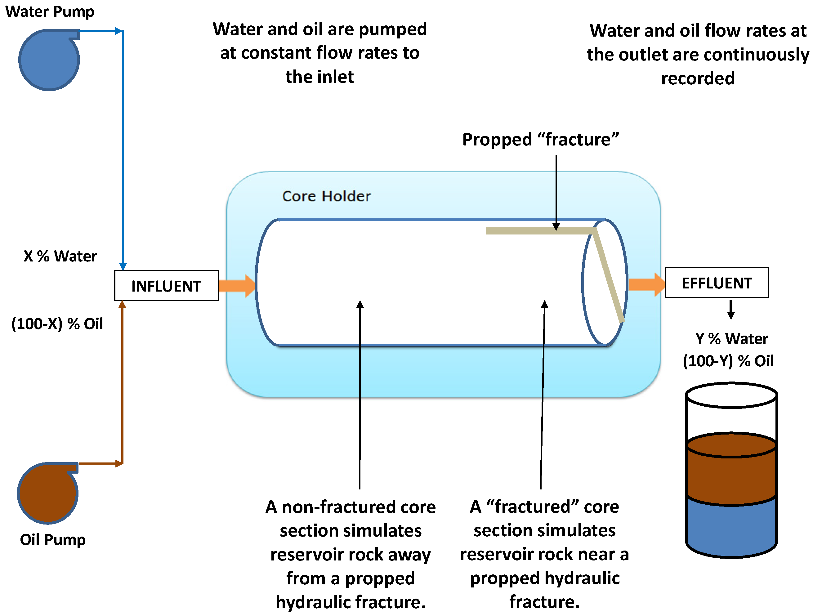
  • Transfer the wet core sample into the core holder, seal the core with confining pressure, inject water through the core, and calculate core permeability.
  • Inject oil (43° API) into the core until the desired water saturation (45% to 50%) is reached.
  • Remove the core sample from the core holder and cut a 6-inch-long (0.1 inch and 0.2 inches wide) “fracture” along the diameter of the core.
  • Fill the “fracture” with proppant particles, transfer the core sample into the core holder, and seal the core with confining pressure.
  • Inject water and oil with deigned water-cut 40% at 5 cc/min through the core and record water and oil-flow volumes every one minute at the outlet.
  • Stop fluid injection when the effluent water-cut reaches the influent water-cut.

3. Experimental Result

Figure 8 presents a comparison of water-cut profiles for systems with PC-OW-1 40/80 and PC-OW-2 40/80 proppants in 0.1-inch fractures in PB-SS cores. It shows that water breaks through into the PC-OW-1 40/80 proppant pack at 0.27 PV of two-phase injection and water breaks through into the PC-OW-2 40/80 proppant pack at 0.36 PV of two-phase injection. The delayed water breakthrough time into the PC-OW-2 40/80 is expected because this proppant pack has an oil contact angle (29.63°) that is lower than the oil contact angle of the PC-OW-1 40/80 proppant pack (75.58°), while both proppant packs have water contact angles of greater than 90°.
Figure 9 shows a comparison of water-cut profiles for systems with PC-OW-1 40/80 and PC-OW-2 40/80 proppants in 0.1-inch fractures in UGB-SS cores. It indicates that water breaks through into the PC-OW-1 40/80 proppant pack at 0.34 PV of two-phase injection and water breaks through into the PC-OW-2 40/80 proppant pack at 0.38 PV of two-phase injection. Again, the delayed water breakthrough time into the PC-OW-2 40/80 is expected because the oil contact angle (29.63°) of this proppant pack is lower than that of the PC-OW-1 40/80 proppant pack (75.58°), while both proppant packs have water contact angles of greater than 90°.
Figure 10 illustrates a comparison of water-cut profiles for systems with PC-OW-1 20/40 and PC-OW-2 20/40 proppants in 0.2-inch fractures in UGB-SS cores. It shows that water breaks through into the PC-OW-1 20/40 proppant pack at 0.36 PV of two-phase injection and water breaks through into the PC-OW-2 20/40 proppant pack at 0.33 PV of two-phase injection. It was expected that the water breakthrough time into the PC-OW-2 20/40 would be delayed due to the lower oil contact angle of the proppant pack. However, this delay did not occur. The reason is believed to be because the water contact angle for the proppant pack is less than 90°. Although its water contact angle of 61.45° is higher than its oil contact angle of 22.5°, the low water viscosity (1 cp) and high oil viscosity (4.7 cp) might cause accelerated water breakthrough. The viscosity effect can be explained using the analytical model presented by Zhang et al. [30]:
v =   r c σ cos θ 4 μ x
where v is imbibition velocity, rc is the equivalent radius of the pore space, σ is interfacial tension, θ is the contact angle, μ is fluid viscosity, and x is the imbibition distance. This equation implies that the imbibition velocity of the wetting phase is directly proportional to the interfacial tension and cosine of contact angle, and inversely proportional to the viscosity of the completing fluid. In this test case, the low viscosity of water might have caused the early water breakthrough in the oil-wet PC-OW-1 20/40 proppant pack.
Figure 11 shows a comparison of water-cut profiles for systems with PC-OW-1 40/80 proppants in 0.2-inch fractures in PB-SS and UGB-SS cores. It indicates that water breaks through into the PC-OW-1 40/80 proppant pack in a PB-SS core at 0.36 PV of two-phase injection and water breaks through into the PC-OW-1 40/80 proppant pack in a UGB-SS core at 0.38 PV of two-phase injection. This comparison implies an insignificant effect of sandstone petrophysical properties on the water breakthrough, although the sandstone permeabilities are different by 6-fold.
This experimental study shows that the effectiveness of the oil-wet proppant for AORW depends on the oil contact angle on the surface of the proppant pack. The mechanism of the oil-wet proppant promoting oil flow from sandstone to the proppant packs in fractures may be the degree of affinity-induced oil imbibition inside the sandstone into the proppant pack. As illustrated in Figure 12, there may exist channels for water and oil flow in sandstones. This affinity-induced imbibition may result in the connection of oil flow channels inside the sandstone to the oil-wet proppant pack. The oil imbibition is promoted by capillary pressure, which is a strong function of the oil contact angle. The lower the contact angle is, the faster the oil imbibition is. The more the oil-wet proppants are, the more the connected the oil channels are.

4. Conclusions

An innovative method was developed for determining the contact angles of fracture proppant packs. The effect of oil contact angles of four oil-wet fracture proppant packs on the competing water/oil flow from sandstone cores to the packs were investigated in this study. Two sandstone cores (Parker Berea and Upper Gray Berea) with 0.1-inch and 0.2-inch-wide “fractures” were used in this study. The following conclusions are drawn:
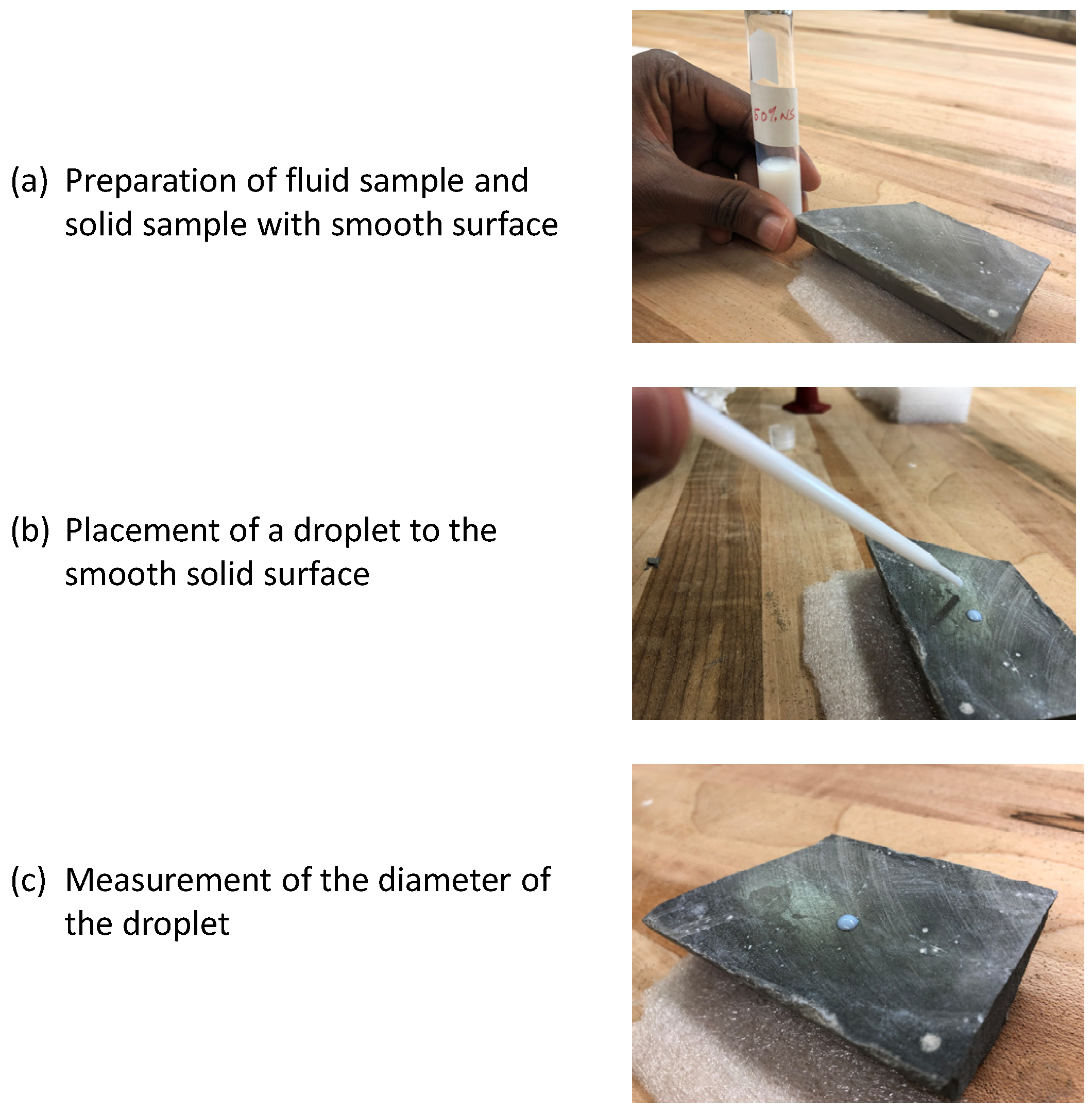
  • The newly developed method for determining the contact angle of fracture proppant pack gives a similar result for the water–stainless steel 304 system given in the literature with a difference of 3%. It gives a similar result for the water–copper system given by the literature with a difference of 3.5%. Therefore, the new method is considered valid for determining liquid contact angle on the smooth surfaces of solid particles. However, no data are found from the literature to validate the new method in determining the liquid contact angle on the surface of proppant packs.
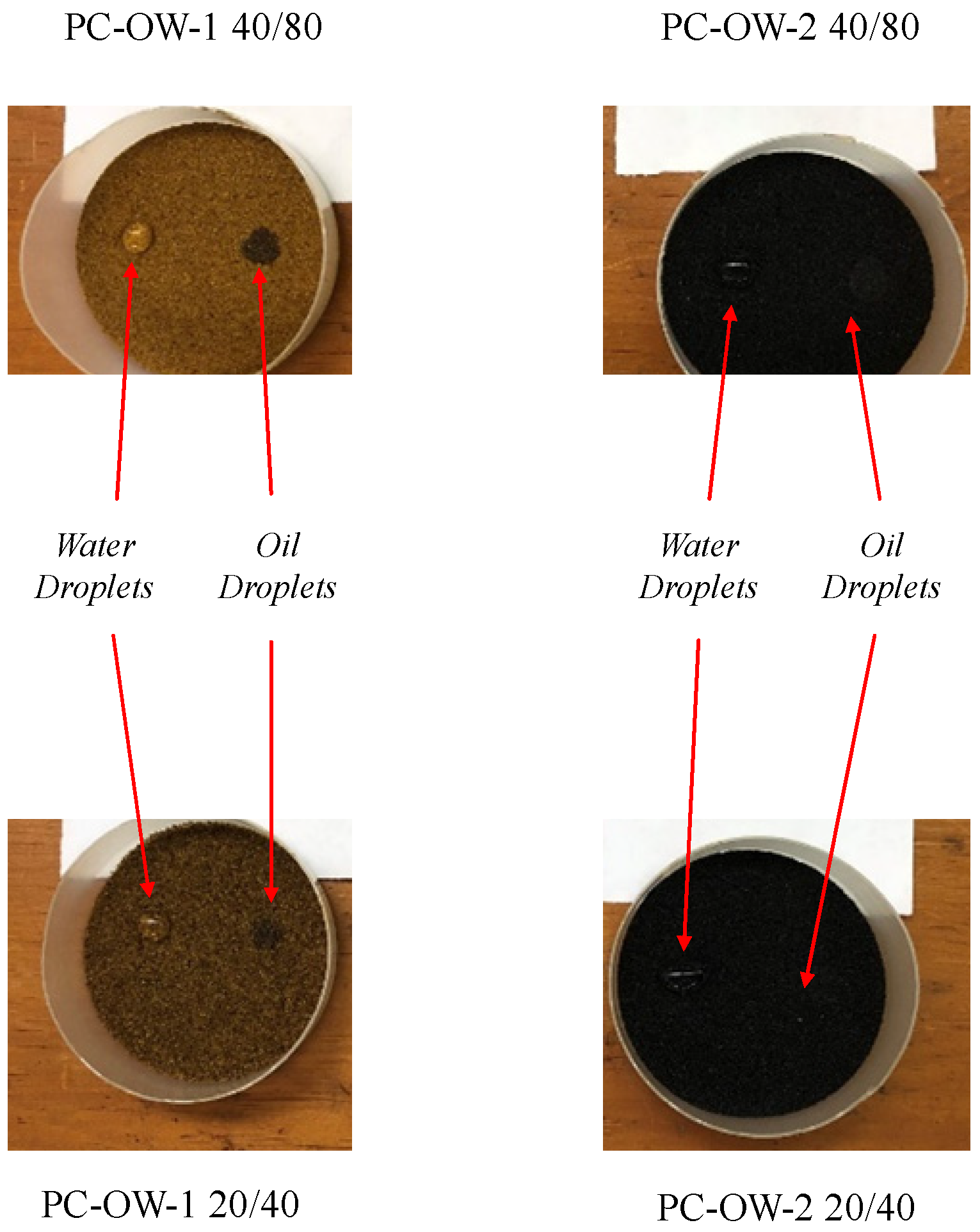
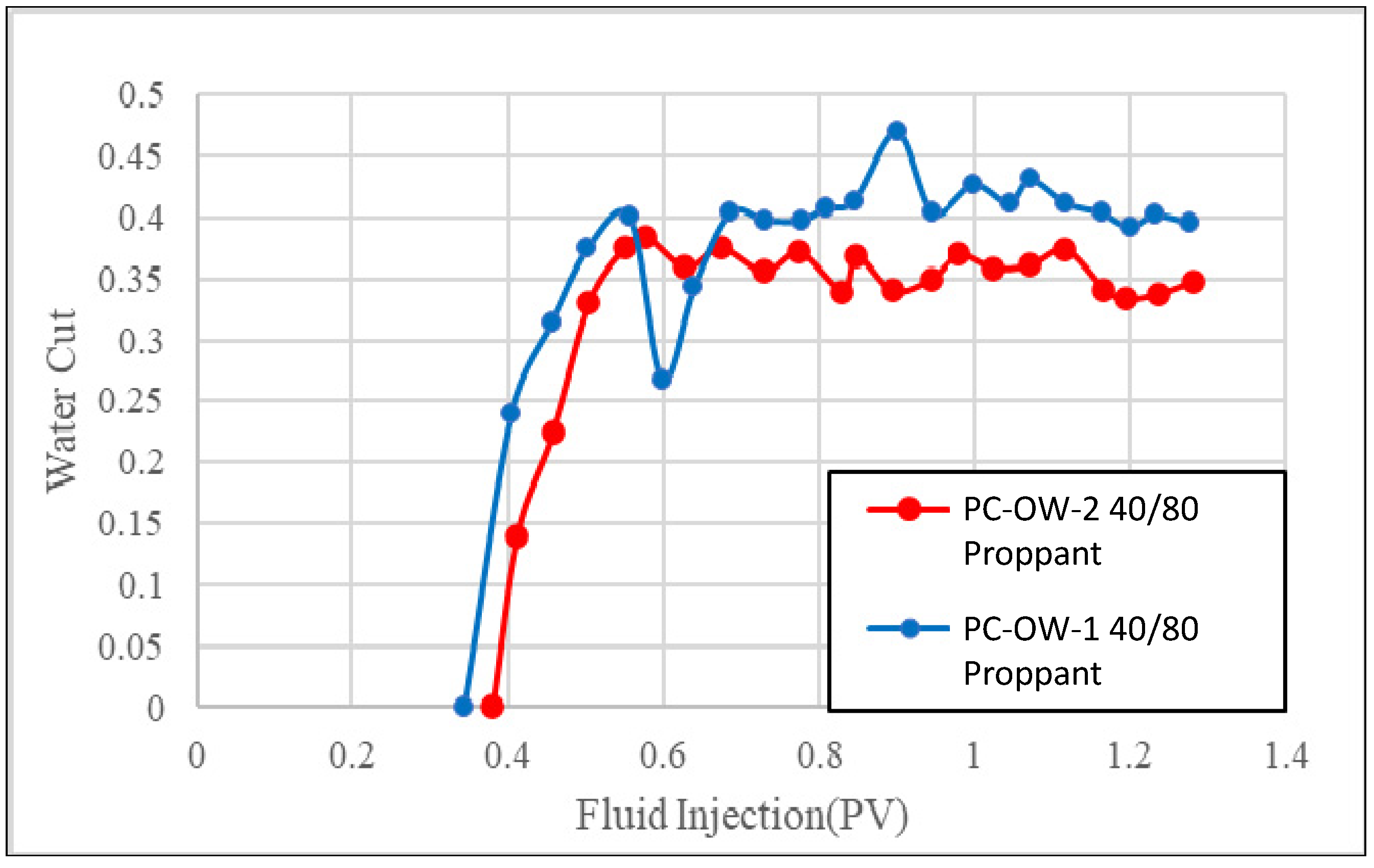
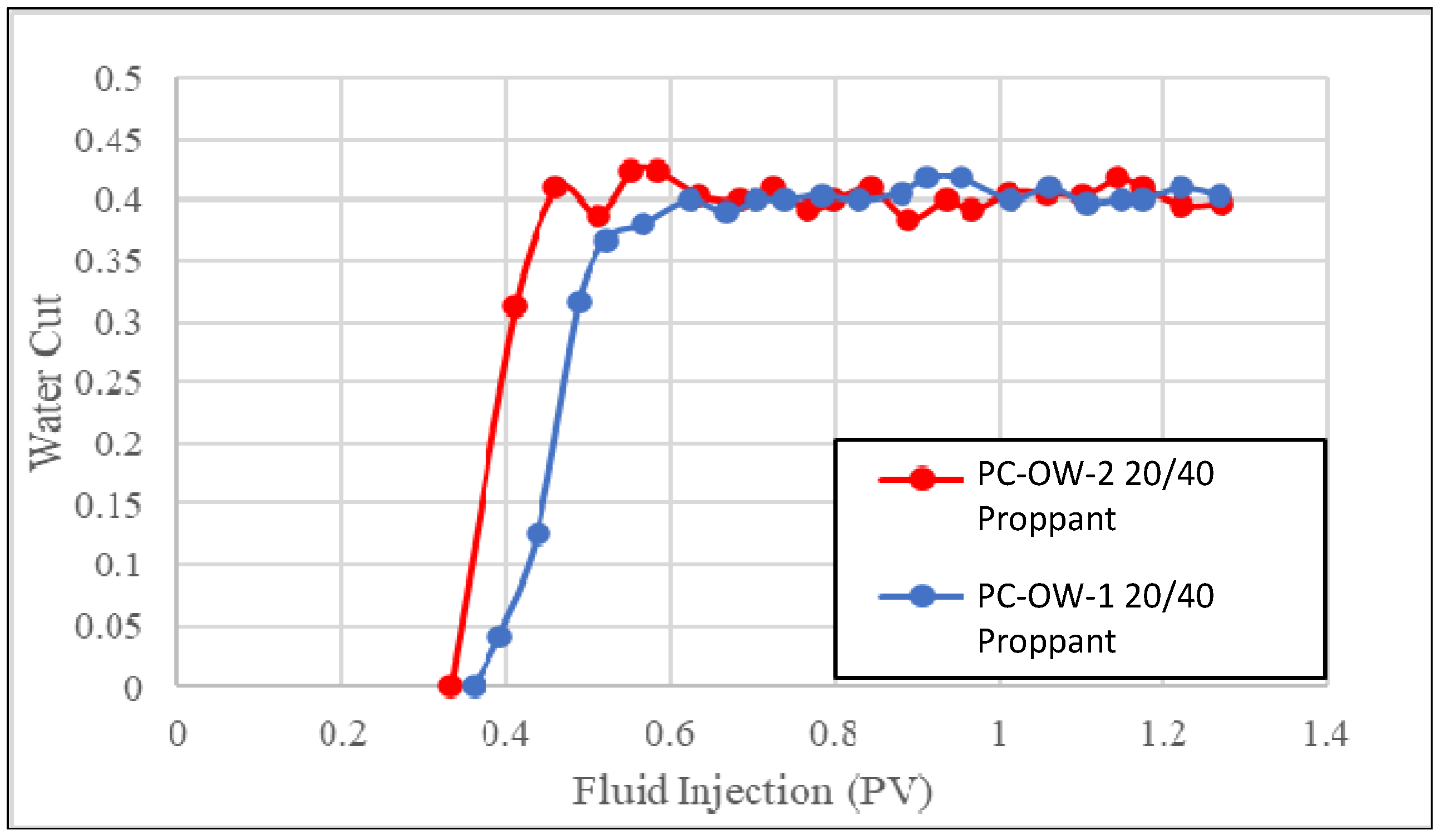
  • The PC fracture proppant packs with water contact angles greater than 90° and oil contact angles significantly less than 90° can be considered as oil-wet proppants. The experimental result from testing with two sandstones and two fracture widths indicates that reducing the oil contact angle of oil-wet proppants can improve the AORW performance of proppant packs through increasing capillary force and thus promoting oil imbibition into the proppant packs.
  • The PC fracture proppant packs with water contact angles less than 90° and oil contact angles less than 90° may be considered as mixed-wet proppants. Their AORW performance depends on water and oil viscosities and should be tested in laboratories before the proppant is considered for well fracturing operations.
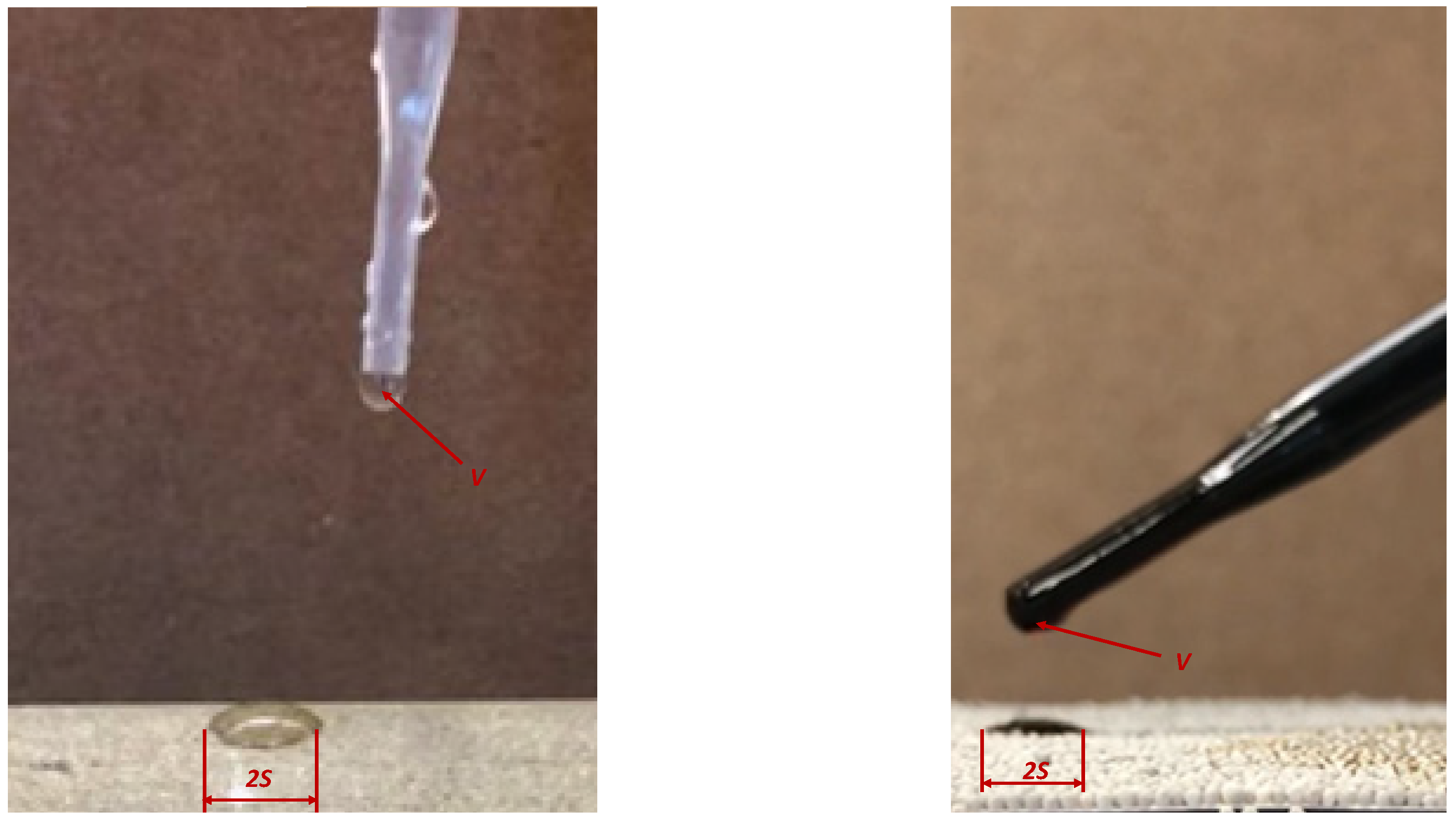
  • The new method for contact angle measurement was developed based on the assumption that the liquid droplet on the surface of the proppant pack assumes a shape of a truncated sphere. This assumption may not be valid for large droplets where gravitational force makes the droplets flat. It is worthwhile to investigate the critical size of droplets below which the assumption of sphere truncation is valid. A potential means of evaluating the critical size of the droplet is to perform analysis with Eötvös number (Eo) or Bond number (Bo), which is a dimensionless number measuring the importance of gravitational forces compared to surface tension forces to characterize the shape of bubbles or drops moving in a surrounding fluid. This is to be investigated in future studies. The new method may not be accurate for situations where the proppant size is large or the contact angle is very small. In these conditions, the liquid would sink into the proppant pack quickly without forming a stable droplet. The critical proppant size and the minimum permissible contact angle should be investigated in future studies.

Author Contributions

Conceptualization, B.G.; methodology, M.W.; software, M.W.; validation, B.G.; formal analysis, M.W.; investigation, M.W.; resources, B.G.; data curation, M.W.; writing—original draft preparation, M.W.; writing—review and editing, B.G.; visualization, M.W.; supervision, B.G.; project administration, B.G.; funding acquisition, B.G. All authors have read and agreed to the published version of the manuscript.

Funding

This research was funded by BIRD grant number EC-19 Fossil Energy and the APC was funded by the University of Louisiana at Lafayette.

Informed Consent Statement

Not applicable.

Acknowledgments

The authors are grateful to BIRD for funding the project “Safe, sustainable, and resilient development of offshore reservoirs and natural gas upgrading through innovative science and technology: Gulf of Mexico—Mediterranean”, through Contract No. EC-19 Fossil Energy.

Conflicts of Interest

The authors declare no conflict of interest.

Appendix A. Derivation of an Equation for Determining Contact Angle on the Basis of Droplet Measurement

Figure A1 shows a liquid droplet placed on the smooth surface of a solid sample. If the volume of the droplet is known and the diameter of the droplet is measured on the surface, an equation can be derived to estimate the contact angle.
Assuming that an amount of liquid dropped on the solid surface takes a shape of a truncated sphere, the shaded area in Figure A2 shows the cross-section of the liquid droplet.
Figure A1. Procedure of placing a fluid droplet to the solid sample with smooth surface.
Sustainability 14 03766 g0a1
Figure A2. Cross-section of a liquid droplet on the surface of a solid.
Sustainability 14 03766 g0a2
The volume of the liquid phase is expressed as
V = π 6 H ( 3 S 2 + H 2 )
where V is the volume, 2S is the base diameter of liquid droplet (sphere segment), and H is the height of the liquid droplet. If the volume V is known before dropping and the diameter S is measured after dropping, the H can be solved from Equation (A1) to give
H 3 + 3 S 2 H 6 V π = 0
which gives a real root of
H = 3 ( 4 B 3 + 27 C 2 ) + 9 C 3 18 3 2 3 3 B 3 ( 4 B 3 + 27 C 2 ) + 9 C 3
where
B = 3 S 2
and
C = 6 V π
Geometrical relation gives
tan β = S H
Because β = π θ 2 , Equation (A6) becomes
tan ( π θ 2 ) = S H
which results in
θ = π 2 tan 1 ( S H )

References

  1. Mao, D.; Miller, D.S.; Karanikas, J.M.; Lake, E.A.; Fair, P.S.; Liu, X. Influence of Finite Hydraulic-Fracture Conductivity on Unconventional Hydrocarbon Recovery with Horizontal Wells; Society of Petroleum Engineers: Rechardson, TX, USA, 2017. [Google Scholar] [CrossRef]
  2. Longoria, R.A.; Liang, T.; Huynh, U.T.; Nguyen, Q.P.; DiCarlo, D.A. Water Blocks in Tight Formations: The Role of Matrix/Fracture Interaction in Hydrocarbon-Permeability Reduction and Its Implications in the Use of Enhanced Oil Recovery Techniques; Society of Petroleum Engineers: Rechardson, TX, USA, 2017. [Google Scholar] [CrossRef]
  3. Le, T.D.; Murad, M.A.; Pereira, P.A. A New Matrix/Fracture Multiscale Coupled Model for Flow in Shale-Gas Reservoirs; Society of Petroleum Engineers: Rechardson, TX, USA, 2017. [Google Scholar] [CrossRef] [Green Version]
  4. Safari, R.; Lewis, R.; Ma, X.; Mutlu, U.; Ghassemi, A. Infill-Well Fracturing Optimization in Tightly Spaced Horizontal Wells; Society of Petroleum Engineers: Rechardson, TX, USA, 2017. [Google Scholar] [CrossRef]
  5. Zhang, F.; Zhu, H.; Zhou, H.; Guo, J.; Huang, B. Discrete-Element-Method/Computational-Fluid-Dynamics Coupling Simulation of Proppant Embedment and Fracture Conductivity after Hydraulic Fracturing; Society of Petroleum Engineers: Rechardson, TX, USA, 2017. [Google Scholar] [CrossRef]
  6. Zhu, H.; Shen, J.; Zhang, F. A fracture conductivity model for channel fracturing and its implementation with Discrete Element Method. J. Pet. Sci. Eng. 2018, 172, 149–161. [Google Scholar] [CrossRef] [Green Version]
  7. He, H.; Senetakis, K. A micromechanical study of shale rock-proppant composite interface. J. Pet. Sci. Eng. 2020, 184, 106542. [Google Scholar] [CrossRef]
  8. Mehmood, F.; Liao, J.; Hou, M.Z.; Zahoor, M.K.; Xiong, Y. Optimization of hydraulic fracturing with rod-shaped proppants for improved recovery in tight gas reservoirs. Geomech. Geophys. Geo-Energy Geo-Resour. 2022, 8, 38. [Google Scholar] [CrossRef]
  9. Shaibu, R.; Guo, B.; Wortman, P.; Lee, J. Stress-Sensitivity of Fracture Conductivity of Tuscaloosa Marine Shale cores. J. Pet. Sci. Eng. 2022, 210, 110042. [Google Scholar] [CrossRef]
  10. Zhang, Y.; Wu, Y.; Teng, Y.; Peng, S. Experiment study on the evolution of permeability and heat recovery efficiency in fractured granite with proppants. Geomech. Geophys. Geo-Energy Geo-Resour. 2022, 8, 3. [Google Scholar] [CrossRef]
  11. Dong, K. Effect of Ceramic Proppant Surface Wettability on Oil Flow Efficiency in Hydraulic-Fractured Wells. Int. J. Eng. Res. Dev. 2018, 14, 13–22. [Google Scholar]
  12. Dong, K.; Wang, M.; Zhang, C. Effect of wettability of ceramic proppant surface in guar gum solution on the oil flow efficiency in fractures. Pet. J. 2018, 5, 388–396. [Google Scholar] [CrossRef]
  13. Dong, K.; He, W.; Wang, M. Effect of surface wettability of ceramic proppant on oil flow performance in hydraulic fractures. Energy Sci. Eng. 2019, 7, 504–514. [Google Scholar] [CrossRef] [Green Version]
  14. Washburn, E.W. The dynamics of capillary flow. Phys. Rev. 1921, 17, 273. [Google Scholar] [CrossRef]
  15. Xiao, D.; Wang, M.; Guo, B.; Weng, D. Effect of surface wetting behavior of ceramic proppant on the two-phase flow across the interface of sandstone and fracture. Energy Sci. Eng. 2020, 8, 1330–1336. [Google Scholar] [CrossRef]
  16. Dove, J.W.; Buckton, G.; Doherty, C. A comparison of two contact angle measurement methods and inverse gas chromatography to assess the surface energies of theophylline and caffeine. Int. J. Pharm. 1996, 138, 199–206. [Google Scholar] [CrossRef]
  17. Awasthi, A.; Bhatt, Y.J.; Garg, S.P. Measurement of contact angle in systems involving liquid metals. Meas. Sci. Technol. 1996, 7, 753. [Google Scholar] [CrossRef]
  18. Hung, Y.L.; Chang, Y.Y.; Wang, M.J.; Lin, S.Y. A simple method for measuring the superhydrophobic contact angle with high accuracy. Rev. Sci. Instrum. 2010, 81, 065105. [Google Scholar] [CrossRef] [PubMed]
  19. Meiron, T.S.; Marmur, A.; Saguy, S. Contact angle measurement on rough surfaces. Rev. Sci. Instrum. 2004, 274, 637–644. [Google Scholar] [CrossRef] [PubMed]
  20. Cui, Z.; Binks, B.P.; Clint, J.H. Determination of contact angles on microporous particles using the thin-layer wicking technique. Langmuir 2005, 21, 8319–8325. [Google Scholar] [CrossRef] [PubMed]
  21. Iliev, S.; Pesheva, N. Nonaxisymmetric drop shape analysis and its application for determination of the local contact angles. J. Colloid Interface Sci. 2006, 301, 677–684. [Google Scholar] [CrossRef] [PubMed]
  22. Liu, T.L.; Kim, C.J.C. Contact Angle Measurement of Small Capillary Length Liquid in Super-repelled State. Sci. Rep. 2017, 7, 740. [Google Scholar] [CrossRef] [PubMed]
  23. Chini, S.F.; Amirfazli, A. A method for measuring contact angle of asymmetric and symmetric drops. Rev. Sci. Instrum. 2011, 388, 29–37. [Google Scholar] [CrossRef]
  24. Parmar, J.S.; Dehghanpour, H.; Kuru, E. Unstable Displacement: A Missing Factor in Fracturing Fluid Recovery. In Proceedings of the SPE Canadian Unconventional Resources Conference, Calgary, AB, Canada, 30 October–1 November 2012. SPE 162649. [Google Scholar]
  25. Moajil, A.A.; Alghizzi, A.; Alsalem, A.; AlDarweesh, A. Advanced HSP Ceramic Proppants—An Evaluation and Effect of Fines on Proppant Pack Conductivity. In Proceedings of the SPE Trinidad and Tobago Section Energy Resources Conference, Port of Spain, Trinidad and Tobago, 25–26 June 2018. SPE-191182-MS. [Google Scholar]
  26. Al-Boghail, F.; Moajil, A.A.; Al-Arawi, A.; Al-Darwish, S. Direct Approach for Contact Angle Measurement of Neutral Wet HSP Proppants. In Proceedings of the SPE Asia Pacific Oil & Gas Conference and Exhibition, Perth, Australia, 20–22 October 2020. SPE-202287-MS. [Google Scholar]
  27. FTA (FIRST TENANGSTROMS). Contact Angle and Surface Energy Measurements on Steel. 19 July 2003. Available online: https://www.firsttenangstroms.com/ (accessed on 10 January 2022).
  28. KSI (KINO Scientific Instrument Inc.). Contact Angle of Water on Smooth Surfaces and Wettability. 2022. Available online: http://www.uskino.com/articleshow_113.html (accessed on 10 January 2022).
  29. Evgeniya, O.; Feoktistov, D.; Kuznetsov, G. Investigation of drop dynamic contact angle on copper surface. In Proceedings of the EPJ Web Conference, Paris, France, 20 August 2015; Volume 82, p. 01053. [Google Scholar] [CrossRef] [Green Version]
  30. Zhang, P.; Guo, B.; Liu, N. Numerical Simulation of CO2 Migration into Cement Sheath of Oil/Gas Wells. J. Nat. Gas Sci. Eng. 2021, 94, 104085. [Google Scholar] [CrossRef]
Figure 1. Placement of liquid droplet to the surface of a proppant pack.
Sustainability 14 03766 g001
Figure 2. Measurements of diameters of wet areas on the surfaces of proppant packs.
Sustainability 14 03766 g002
Figure 3. Images of water droplets on the surfaces of a stainless steel 304 sample and a copper sample. (a) Water–Air–SS System, (b) Water–Air–Copper System.
Sustainability 14 03766 g003
Figure 4. Images of 4 PC proppant packs with water and oil droplets placed at surfaces.
Sustainability 14 03766 g004
Figure 5. A schematic of water–oil 2-phase injection system.
Sustainability 14 03766 g005
Figure 6. Experimental setup for water–oil 2-phase injection.
Sustainability 14 03766 g006
Figure 7. A flow diagram to show water–oil 2-phase injection.
Sustainability 14 03766 g007
Figure 8. Water-cut profiles for PC-OW-1 40/80 and PC-OW-2 40/80 proppants in 0.1 in fractures in PB-SS.
Sustainability 14 03766 g008
Figure 9. Water-cut for PC-OW-1 40/80 and PC-OW-2 40/80 proppants in 0.1 in. fractures in UGB-SS.
Sustainability 14 03766 g009
Figure 10. Water-cut for PC-OW-1 20/40 and PC-OW-2 20/40 proppants in 0.2 in. fractures in UGB-SS.
Sustainability 14 03766 g010
Figure 11. Water-cut profiles for PC-OW-1 40/80 proppant in 0.2 in. fractures in PB-SS and UGB-SS.
Sustainability 14 03766 g011
Figure 12. A sketch to illustrate the potential development of oil channels inside sandstones due to the oil affinity to the oil-wet proppants.
Sustainability 14 03766 g012
Table 1. Petrophysical Properties of Berea Sandstone Samples.
Petrophysical PropertiesPB-SSUGB-SS
Core 1Core 2Core 1Core 2Core 3Core 4
Porosity (%)16.1915.8119.219.2519.2719.06
Water Permeability (md)8968685249
Water Saturation (%)50.250.145.445.345.445.5
Table 2. Measured droplet parameters and calculated contact angles.
Proppant SampleDroplet Volume (cc)Droplet Diameter (cm)Calculated Contact Angle (deg)
WaterOilWaterOilWaterOil
PC-OW-1 40/800.0450.0250.43130.515114.9175.58
PC-OW-2 40/800.0450.0250.5340.77794.4729.63
PC-OW-1 20/400.0450.0250.4590.551109.0167.08
PC-OW-2 20/400.0450.0250.7010.85761.4522.5
Publisher’s Note: MDPI stays neutral with regard to jurisdictional claims in published maps and institutional affiliations.

