Author Contributions
Conceptualization, G.M.G., K.A.M.O., F.R.G.T., L.A.M.D. and B.E.A.; methodology, G.M.G., K.A.M.O., F.R.G.T., L.A.M.D. and B.E.A.; software, G.M.G., K.A.M.O. and F.R.G.T.; validation, G.M.G., K.A.M.O. and F.R.G.T.; formal analysis, G.M.G., K.A.M.O., F.R.G.T. and B.E.A.; writing—original draft, G.M.G., K.A.M.O. and F.R.G.T.; writing—review and editing, L.A.M.D. and B.E.A.; visualization, G.M.G., K.A.M.O. and F.R.G.T.; supervision, L.A.M.D. and B.E.A.; funding acquisition, L.A.M.D. and B.E.A. All authors have read and agreed to the published version of the manuscript.
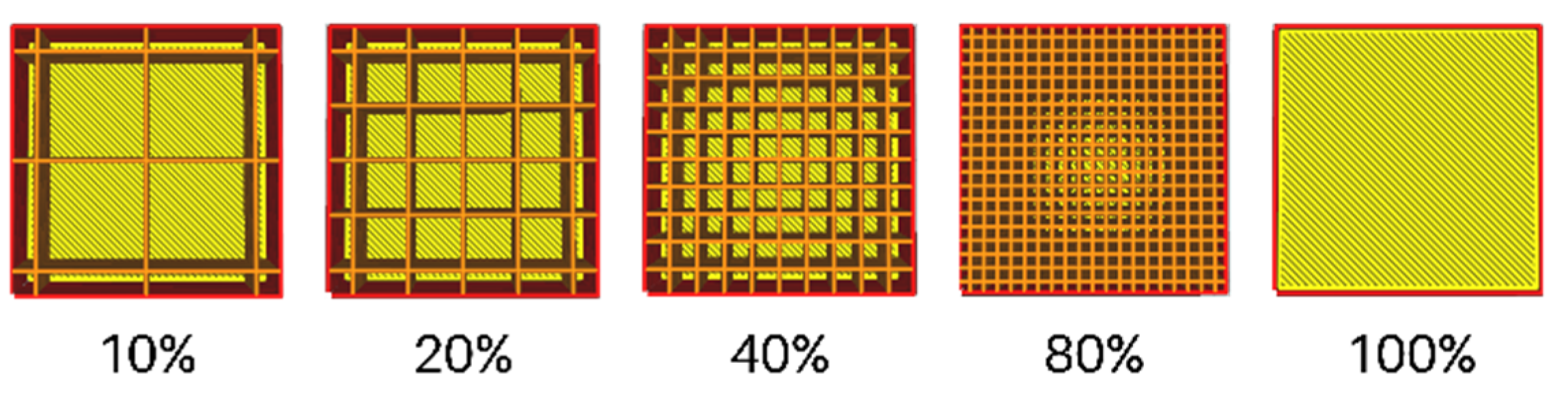
Figure 1.
Grid infill at different infill densities.
Figure 1.
Grid infill at different infill densities.
Figure 3.
BEM predicted power coefficient for the proposed blade design and old design adapted from [
26,
30].
Figure 3.
BEM predicted power coefficient for the proposed blade design and old design adapted from [
26,
30].
Figure 4.
Specimen drawing: ASTMD638 type V standard [
33].
Figure 4.
Specimen drawing: ASTMD638 type V standard [
33].
Figure 5.
Tensile test experiment (a) before test, (b) failure after test.
Figure 5.
Tensile test experiment (a) before test, (b) failure after test.
Figure 6.
(a) Simulated tensile test experiment and (b) comparison of results.
Figure 6.
(a) Simulated tensile test experiment and (b) comparison of results.
Figure 7.
Sandwich models and printed samples with varying lattice structure configuration for 3-point bend test.
Figure 7.
Sandwich models and printed samples with varying lattice structure configuration for 3-point bend test.
Figure 8.
Experimental bending test setup.
Figure 8.
Experimental bending test setup.
Figure 9.
FEA bending test setup where point A is a pin connection to avoid rigid body motion, B and C are pin supports, E as the load pin with D as the remote force.
Figure 9.
FEA bending test setup where point A is a pin connection to avoid rigid body motion, B and C are pin supports, E as the load pin with D as the remote force.
Figure 10.
Simulation setup showing the blade with applied remote forces and fixed support.
Figure 10.
Simulation setup showing the blade with applied remote forces and fixed support.
Figure 11.
Solid blade model.
Figure 11.
Solid blade model.
Figure 12.
Shell-Spar blade model.
Figure 12.
Shell-Spar blade model.
Figure 13.
Shell–infill blade model.
Figure 13.
Shell–infill blade model.
Figure 14.
Turbine blade with infill orientation in ANSYS.
Figure 14.
Turbine blade with infill orientation in ANSYS.
Figure 15.
Visual representation of blade turbine sections with 0-degree orientation.
Figure 15.
Visual representation of blade turbine sections with 0-degree orientation.
Figure 16.
Load deflection curves from bend test. Triangle infill (a) out of plane, 0°, (b) out of plane, 90°, (c) in plane, 0°, (d) in plane, 90°. Hexagonal infill (e) out of plane, 0°, (f) out of plane, 90°, (g) in plane, 0°, (h) in plane, 90°.
Figure 16.
Load deflection curves from bend test. Triangle infill (a) out of plane, 0°, (b) out of plane, 90°, (c) in plane, 0°, (d) in plane, 90°. Hexagonal infill (e) out of plane, 0°, (f) out of plane, 90°, (g) in plane, 0°, (h) in plane, 90°.
Figure 17.
Load Deflection Curves from Bend Test.
Figure 17.
Load Deflection Curves from Bend Test.
Figure 18.
Solid blade model simulation with PLA.
Figure 18.
Solid blade model simulation with PLA.
Figure 19.
Solid blade model (carbon fiber with onyx base material).
Figure 19.
Solid blade model (carbon fiber with onyx base material).
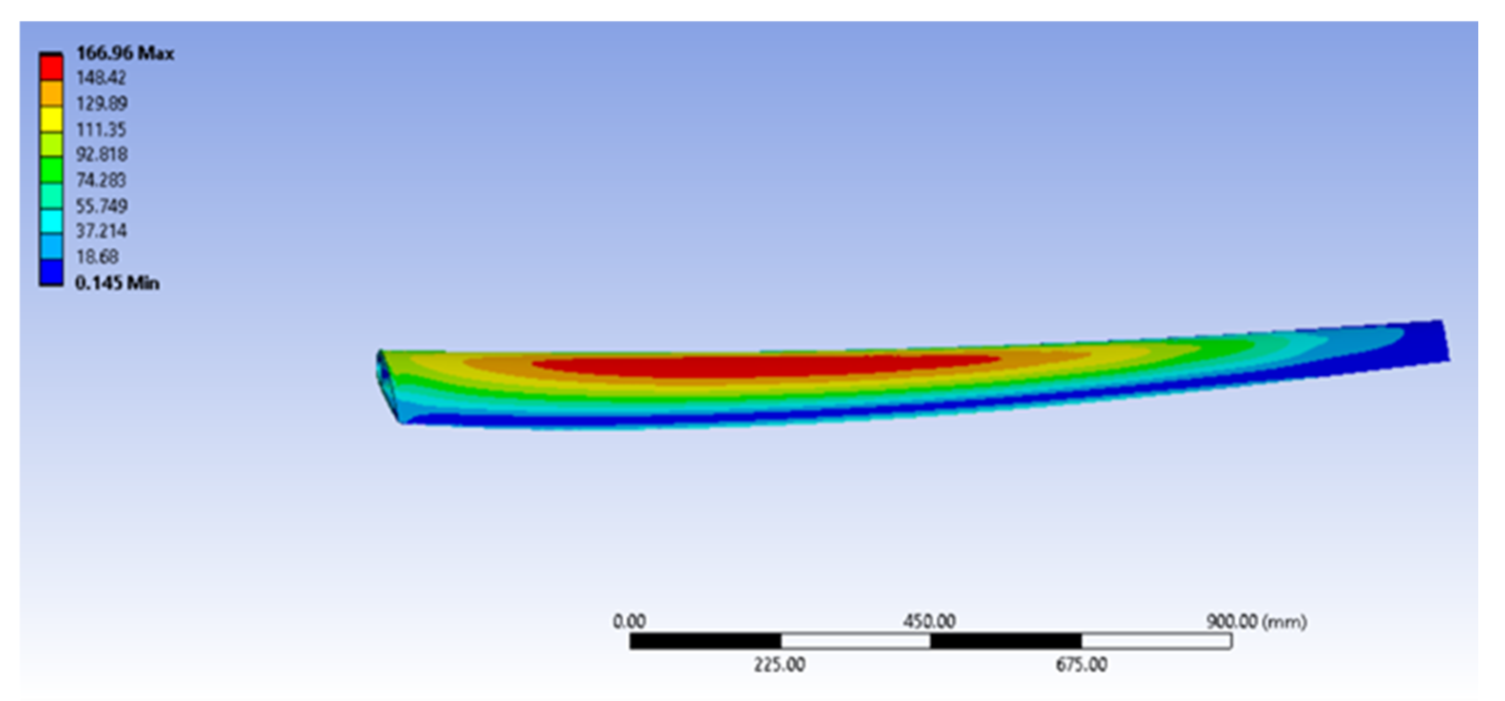
Figure 20.
Directional deformation (mm) along the Z axis of the final shell-spar model (carbon fiber with onyx base material).
Figure 20.
Directional deformation (mm) along the Z axis of the final shell-spar model (carbon fiber with onyx base material).
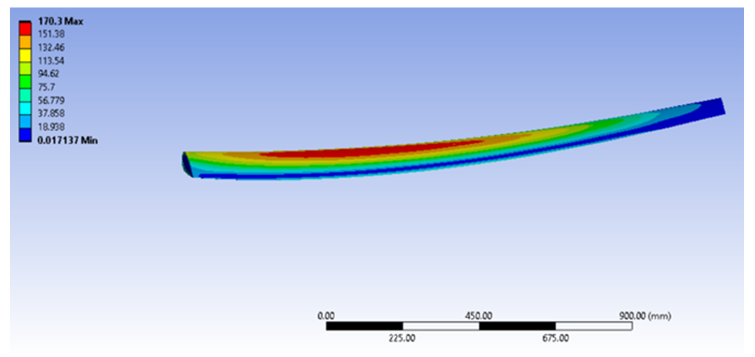
Figure 21.
Directional deformation (mm) along the Z axis of shell–infill model (carbon fiber with onyx base material).
Figure 21.
Directional deformation (mm) along the Z axis of shell–infill model (carbon fiber with onyx base material).
Figure 22.
Von Mises stress (MPa) of shell-spar model (carbon fiber with onyx base material).
Figure 22.
Von Mises stress (MPa) of shell-spar model (carbon fiber with onyx base material).
Figure 23.
Von Mises stress (MPa) of shell–infill model (carbon fiber with onyx base material).
Figure 23.
Von Mises stress (MPa) of shell–infill model (carbon fiber with onyx base material).
Figure 24.
Angle vs. deflection trend of the turbine blade with different infill orientations. (a) Reduced y-axis range plot and (b) enlarged y-axis range plot.
Figure 24.
Angle vs. deflection trend of the turbine blade with different infill orientations. (a) Reduced y-axis range plot and (b) enlarged y-axis range plot.
Table 1.
Reviewed literature matrix.
Table 1.
Reviewed literature matrix.
| Authors | HAWT/HATT | Additive Manufacturing | Infill Pattern | Flexure Testing | Simulation |
|---|
| Kim, S. et al. [22] | HAWT | Yes | Yes | No | Yes |
| Noronha, N. Munishamaiah, K. [31] | HAWT | No | No | No | Yes |
| Cho, P. et al. [13] | N/A | Yes | Yes | Yes | Yes |
| Kim, S. et al. [11] | N/A | Yes | Yes | Yes | Yes |
| Kalyani, K. et al. [10] | N/A | Yes | No | No | Yes |
| Bassett et al. [32] | HAWT | Yes | Yes | No | No |
| Danao et al. [26] | HATT | No | No | No | Yes |
| Bhandari, S. and Lopez-Anido, R [24] | N/A | Yes | Yes | Yes | Yes |
Table 2.
ASTMD638 type V standard.
Table 2.
ASTMD638 type V standard.
| Dimensions | Type V (mm) | Tolerances |
|---|
| W—Width of narrow section | 3.18 | ±0.5 |
| L—Length of narrow section | 9.53 | ±0.5 |
| WO—Width overall, min | 9.53 | +3.18 |
| LO—Length overall, min | 63.5 | No max |
| G—Gage length | 7.62 | 0.25 |
| D—Distance between grips | 25.4 | ±5 |
Table 3.
Turbine blade specifications [
26].
Table 3.
Turbine blade specifications [
26].
| Radial Position (m) | Chord Length (m) | Twist (°) | Foil Profile |
|---|
| 0.4 | 0.250 | 20 | NACA 4424 |
| 0.6 | 0.2312 | 14.5 | NACA 4420 |
| 0.8 | 0.2126 | 11.1 | NACA 4418 |
| 1 | 0.1938 | 8.9 | NACA 4417 |
| 1.2 | 0.175 | 7.4 | NACA 4416 |
| 1.4 | 0.1562 | 6.5 | NACA 4415 |
| 1.6 | 0.1376 | 5.9 | NACA 4414 |
| 1.8 | 0.1188 | 5.4 | NACA 4413 |
| 2 | 0.1 | 5 | NACA 4412 |
Table 4.
Blade force data from BEM Simulation at 2 m/s flow speed adapted from [
26].
Table 4.
Blade force data from BEM Simulation at 2 m/s flow speed adapted from [
26].
| Radial Position (m) | Tangential Force (N) | Normal Force (N) | Resultant Force (N) |
|---|
| 2 | 36.072 | 418.441 | 419.933 |
| 1.8 | 121.475 | 1036.20 | 1043.30 |
| 1.6 | 142.404 | 1041.26 | 1050.95 |
| 1.4 | 151.03 | 969.055 | 980.754 |
| 1.2 | 154.613 | 860.287 | 874.07 |
| 1 | 155.63 | 724.558 | 741.084 |
| 0.8 | 151.657 | 568.066 | 587.962 |
| 0.6 | 134.533 | 393.101 | 415.485 |
| 0.4 | 40.06 | 103.387 | 110.877 |
Table 5.
Material properties of carbon fiber with onyx base [
37].
Table 5.
Material properties of carbon fiber with onyx base [
37].
| Property | Material Properties |
|---|
| Young’s modulus | 60 GPa |
| Poisson’s ratio | 0.3061 |
| Tensile strength | 760 MPa |
| Flexural strength | 540 MPa |
Table 6.
Homogenized properties of the PLA lattice.
Table 6.
Homogenized properties of the PLA lattice.
| Property and Direction | Material Properties |
|---|
| Young’s Modulus X | 3.88631 MPa |
| Young’s Modulus Y | 3.88627 MPa |
| Young’s Modulus Z | 86.568 MPa |
| Poisson’s Ratio XY | 0.91915 |
| Poisson’s Ratio YZ | 0.014726 |
| Poisson’s Ratio XZ | 0.014725 |
| Shear Modulus XY | 1.0205 MPa |
| Shear Modulus YZ | 17.484 MPa |
| Shear Modulus XZ | 17.484 MPa |
Table 7.
Homogenized Properties of the Carbon Fiber lattice.
Table 7.
Homogenized Properties of the Carbon Fiber lattice.
| Property and Direction | Material Properties |
|---|
| Young’s Modulus X | 0.37195 GPa |
| Young’s Modulus Y | 0.37199 GPa |
| Young’s Modulus Z | 9 GPa |
| Poisson’s Ratio XY | 0.92441 |
| Poisson’s Ratio YZ | 0.012399 |
| Poisson’s Ratio XZ | 0.012398 |
| Shear Modulus XY | 0.0966 GPa |
| Shear Modulus YZ | 1.8531 GPa |
| Shear Modulus XZ | 1.853 GPa |
Table 8.
Turbine blade configurations and deflection.
Table 8.
Turbine blade configurations and deflection.
| Turbine Blade Model | Description | Deflection (mm) | Deflection (%) |
|---|
| Solid Blade model | Solid Body | 148.61 | 9.288125 |
| Shell-Spar model | 2% of MCL Shell Thickness (5 mm) | 188.52 | 11.7825 |
| Shell-Spar model | 3% of MCL Shell Thickness (7.5 mm) | 161.67 | 10.11 |
| Shell-Spar model | 3.5% of MCL (8.75 mm) | 155.51 | 9.719375 |
| Shell–infill model | 3.596% of MCL Shell Thickness (8.99 mm) + 15% Infill | 155.53 | 9.720625 |


 and
and 


