Abstract
A reciprocating fuel pump system was investigated using a modeling approach. The diesel pump system comprises a variable-sized barrel and plunger. This study investigates the effect of diesel, propane, and DME fuels on the plunger barrel’s deformation and flow rate characteristics. It compares the barrel and plunger displacement as a function of working pressure. Based on the multi-field coupling theory, a numerical fluid–solid thermal coupling model was developed to characterize the operational fluctuations in deformation and clearance. Due to the distinct deformation patterns of the two components, the appropriate clearance for the pump’s head and stem must be set independently. In addition, significant AMESim parameters compared and confirmed the discharge flow rates of three distinct fuels. The results show that the maximum displacement for the plunger stem was 0.00266 mm at 7.5 mm from the top of the stem, which was 6.94% lower than the literature result. The DME fuel showed flow stability initially (from 0.0 to 0.4 s) when using a plunger diameter of 23.85 mm. According to the plunger diameters, the marine fuel injection pump’s discharge flow rates increased, minimizing the wearing between the barrel/plunger. The research findings revealed that the suggested structural and flow rate model is recommended for alternative marine fuel applications.
1. Introduction
A system that injects compressed fuel directly into the cylinders of medium-speed diesel engines is called a reciprocating fuel pump. The pump regulates the amount of fuel oil necessary to produce the needed power, and it is integrated with the engine’s timing to ensure that the engine operates smoothly. A “Bosch-type pump” is a mechanical reciprocating pump consisting of a barrel and a helical plunger for 3D modeling, as shown in Figure 1. Fuel oil with more pressure is required for efficient combustion and smoke reduction in medium-speed diesel engines.
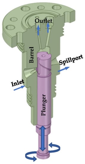
Figure 1.
3D modeling and mechanism of reciprocating marine fuel pump.
Numerous studies have been conducted on high-pressure fuel injection [1,2,3,4,5,6]. Due to high oil costs, there have been reliability issues with using low-quality fuel oil [5,6,7]. The major components of the catalysts are alumina-silicates with diameters of 5–150 µm, an oval shape, and hardness values close to grinding materials. Their reports create scratches on the moving surfaces and accelerate sticking or wear in reciprocating fuel pumps [2,5,6]. A marine high-pressure common rail system using MAP data and empirical calculations in AMESim was modeled by Wang et al. [8]. Their results showed the variation in rail pressure induced by each fuel injection cycle.
Designs for reciprocating fuel pumps that avoid wear and sticking under varying operating circumstances are essential, as is a rising fuel oil supply pressure in recent medium-speed diesel engines for enhancing combustion performance [9,10]. Along these lines, we provide a suitable clearance design approach to increase the lubrication and endurance of piston fuel pumps. Previous research has suggested using circumferential grooving, a tapered shape, partial grooving, and optimal clearance design [11] to enhance the lubrication characteristics of the fuel pump. To reduce stress concentrations at the rollers’ ends, profiles (tapers) were incorporated into cylindrical roller bearings [12]. Grooves were cut into various mechanical components to improve lubrication and heat dissipation [13].
Hong et al. [5] proposed tapered and circumferential grooves to enhance the lubrication characteristics of a fuel pump for medium-speed diesel engines. It was announced that using both circumferential grooves and tapered shapes on the plunger to increase the lubrication characteristics of the pump was more effective than using either one alone. However, only a few research studies [6,13,14] have been conducted on the sticking consent in medium-speed diesel engine fuel pumps, an identical issue known as “hydraulic lock” appears in hydraulic systems such as a spool valve. Borghi [15] proposed that the trouble was primarily inferred by the effect of hydrodynamics resulting from asymmetric pressure distribution around the spool.
Since the pump operates at 1500 bar, deformation should be considered. Elastohydrodynamic lubrication analysis analyzes lubrication system variations [16,17,18,19]. Fluid–structure interaction (FSI) analysis can also consider deformation resulting from fluid pressure. Nevertheless, according to Dhar and Vacca [18], Venner et al. [20], Masjedi and Khonsari [21], and Meng et al. [22], a structural analysis is adequate for this study when the maximum fuel oil supply pressure is used due to the constraint substantially influencing pump deformation. The maximum clearance reduction is only rarely used. Li et al. [23] introduced a rapid and efficient approach for integrating multiple physical domains. A thermal fluid–structure coupling model was developed for the axial piston pump to investigate the temporal and spatial evolution of the valve plate friction pair’s temperature, stress, and deformation. This research is highly significant for ensuring the structural safety of the EHA pump.
In summary, marine diesel engines are widely used for propulsion in shipping, and their efficiency and reliability are critical for the safe and sustainable operation of the vessels. In addition, the fuel injection pump’s structural and flow rate characteristics significantly impact the engine’s performance. However, there is a lack of detailed numerical analysis of the fuel injection pump’s structural and flow rate characteristics in marine diesel engines. Therefore, this study aims to investigate 3D thermal fluid–solid interaction and 1D flow rate characteristic modelings of the different fuels’ effects on structural deformation, film parameters, temperature, velocity, turbulence kinetic energy, and flow rate characteristics of the marine reciprocating fuel pump. The findings of this study can offer valuable guidance for the new design, construction, and operation of fuel injection pumps of medium-speed marine engines.
2. Methodology
2.1. Three-Dimensional Numerical Model of High-Pressure Marine Fuel Injection Pump
The structural study looks at the barrel distortion and plunger below the maximum supply pressure induced by fuel oil compression. The most significant loss in clearance caused by the deformation was also calculated. Furthermore, the thermal fluid–solid analysis simulation required 4–5 h for each scenario. The PC utilized for the investigation was equipped with an AMD Ryzen 5 2.10 GHz CPU and 8 GB of RAM. Deformation occurs at high pressure during the compression stage of the cycle, and clearance is reduced when the magnitude of the plunger deformation exceeds that of the barrel in a specific location. Commercial software is used to compute the computational domain and the magnitude of the deformation (ANSYS 19.2). The most significant clearance reduction was utilized as a design limit to avoid metal-on-metal contact due to deformation.
The dimension detail shown in Figure 2 illustrates the proposed marine fuel injection pump, especially the plunger and the barrel parts. To make it different from other models in the literature [5,7,11,12,14], the proposed model modified the plunger diameter to 23.9 mm and the plunger stem taper to 1.5° × 30 mm. Moreover, the mesh (tetrahedral shape) of Figure 3a depicts the computational model, and fine grids with a tetrahedral element were implemented in the region. Figure 3b illustrates the constraints and disassembly of the barrel, plunger, and fluid domain. In the areas impacted by compressed fuel oil, the plunger’s bottom half was fixed in all directions, and the ultimate supply pressure was implemented. The barrel top and side were fixed in anticipation of twisting in the x and y directions, and the highest supply pressure was also supplied to the compressed fuel oil-affected areas.
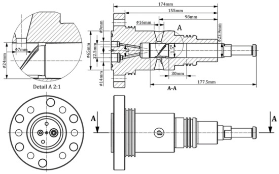
Figure 2.
Detail dimensions of barrel and plunger for the thermal fluid–structure interaction analysis.
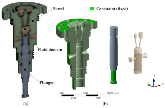
Figure 3.
Grids, constraints, and disassembly parts: (a) computational model grids, (b) disassembly parts and their constraints.
2.2. Computational Fluid–Solid Thermal Coupling Theory and Governing Equations for Marine Fuel Injection Pump
The fluid–solid thermal coupling problem pertains to the fundamental issue of a system wherein the fluid field, solid field, and temperature field coexist and mutually influence one another. Furthermore, the essential variables concurrently computed are fluid flow, solid deformation, and temperature change. The resolution of the flow, solid, and temperature fields in the energy fuel pump necessitate the utilization of fundamental flow equations for the fluid domain [22,24], a thermal performance [25], a thermal equation [26], and mechanical equations [27] in the solid domain, along with consistent boundary conditions at the fluid–solid interface [26,27,28]. Besides, different temperatures and pressure loads can affect model deformation [29,30,31]. This paper employs the method of calculating unidirectional fluid–solid thermal coupling.
In fluid dynamics, the computational domain of the fluid is commonly treated as an incompressible flow subject to the fundamental equations of fluid motion. These equations comprise the conservation of mass, momentum, and energy conservation. The continuity equation can be defined as follows:
The equation governing momentum can be expressed as:
In different directions, we have X momentum:
Y momentum:
Z momentum:
The standard k-ε equation is used to describe turbulence models [32,33]:
- k equation:
- ε equation:
- and:
The energy equation is as follows:
The equation governing the solid field is derived from the three fundamental laws of elastic mechanics: the deformation continuity law, the stress–strain relationship, and the law of motion, as well as the principle of energy conservation.
The thermal conductivity differential equation is as follows:
The equation of force for every direction (x, y, and z) is expressed as:
The constitutive equation is as follows:
The geometric equation is as follows:
The continuity condition must be upheld at the fluid and solid phases’ interface. The principle of energy continuity is kept at the point of the coupling interface, wherein the temperature and heat flow exhibit continuity.
The interface coupling satisfies both kinematic and mechanical conditions, precisely the continuity of displacement and pressure.
The present study establishes a numerical calculation model for the fluid–solid thermal coupling of the energy plunger/barrel utilizing ANSYS 19.2. Initially, a conventional three-dimensional turbulent flow model is employed to resolve the flow and temperature fields of the energy conduit. The Fluent 19.2 solution is integrated with the thermal and structural modules to exchange temperature and pressure loading data. Ultimately, the computation of the solid structure domain is predicated upon the outcomes mentioned above.
The plunger and barrel of the reciprocating fuel pump were subjected to structural analysis. The mathematical model for the structural numerical analysis is depicted in Figure 4. The barrel was attached to the housing, and the plunger moved in a linear reciprocating motion. The plunger’s reciprocating action compressed the gasoline. The elastic modulus of the barrel and plunger was 200 GPa with a Poisson’s ratio of 0.3, and more parameters are listed in Table 1. Figure 4 depicts a flowchart of the structural analysis simulation. The plunger’s head eccentricity ratio was then used to assess whether there was contact.
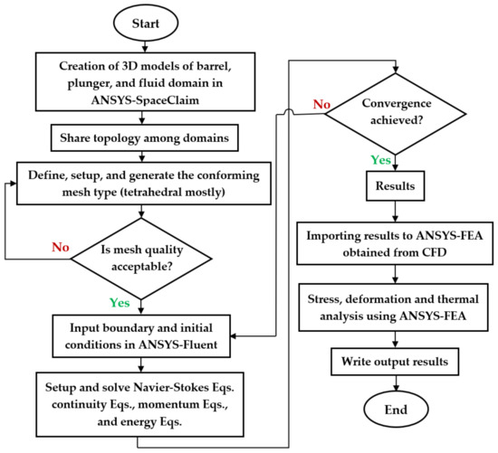
Figure 4.
Flowchart of numerical analysis.

Table 1.
Material properties, input parameters, and boundary conditions for 3D thermal fluid–solid interaction modeling.
Deformation occurs when there is high pressure during the compression stage of the cycle, and clearance is reduced when the amplitude of plunger deformation exceeds that of the barrel in some locations. Finite element method (FEM) commercial software was used to compute the deformation and meshing amplitudes. The most significant decline in clearance was utilized as the design limit to avoid metal-to-metal contact caused by deformation.
Solving the Navier–Stokes equations in the Eulerian frame, the continuous gas phase was handled as a continuum. In contrast, the dispersed phase was addressed by tracking many particles through the flow field [34]. Particles in the dispersed phase can transfer mass, energy, and momentum to the gas phase. In this investigation, the authors neglected these particle–particle interactions. Instead, the authors used a practical k-model of turbulence that included a different formulation of turbulent viscosity and a separate transport equation for the dissipation rate. This realizable k-model outperforms the traditional k-model, incorporating vortices, rotation, and a significantly streamlined curvature [35].
Dimethyl ether (DME) is a substitute for diesel due to its equal cetane number, hydrogen content, self-ignition temperature, and calorific value [36]. The difference in emissions stems from the fact that diesel is not an oxygenated fuel, whereas DME is. As such, diesel produces soot when burned, whereas DME does not. Because of the similarities in cetane between the two fuels, DME may also be utilized in diesel engines with minor modifications to the fuel injection system. LPG and DME qualities are pretty similar, and DME can be utilized as a replacement for LPG because of these similarities [37]. DME and LPG have comparable physicochemical features and handling conditions. When storing DME, it is necessary to use moderate pressurization instead of LPG, which is stored as a liquid. DME has a volumetric energy density as a liquid believed to be 80% of that of propane, a part of LPG. The table shows the similarities in DME and LPG characteristics. Table 2 shows the properties of diesel fuel, propane, and DME.
Table 2.
Properties of diesel, propane, and DME, adapted from Memon et al. [36].
2.3. Description and Modeling of High-Pressure Common Rail Fuel Injection System in AMESim
A high-pressure commonrail fuel injection system’s efficiency is influenced by various factors, including fuel leakage between components, elastic deformation of the high-pressure fuel pipe, diesel compressibility at high pressures and temperatures, and flow rate loss as the fuel passes through cross-sections of various sizes. Its matching architecture is shown in Figure 5a.
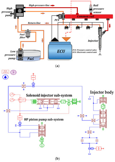
Figure 5.
(a) High-pressure common rail system and (b) 1D modeling of fuel injection pump system in AMESim.
Some assumptions were made based on the system characteristics. First, the fuel temperature disparity was not considered during operations to ensure the pressure could represent the system state. The fluid dynamic development associated with the flows over the pipes is ignored, the cylinders and low-pressure pump volumes are assumed to be infinite, and the pressure is stable. The electrohydraulic valve was expressed as a variable.
The fuel’s compressibility is modeled by the bulk modulus of elasticity (E), Equation (21) [38]:
where an increase in dP generates a decrease in the quantity of a unit amount of liquid—dV. Here, dV/V is a quantity of dimensionless. From Equation (21), fuel pressure as a function of time is:
V denotes the chamber’s simultaneous volume, and dV/dt represents the volume variations induced by mechanical components, the piston, and the inlet and exit flows. Given that the factors influence the fuel’s volume change, Equation (22) can be reformulated as follows:
This is the essential formula for pressure dynamics in each control volume. In Equation (23), Qin denotes the intake flow, Qout represents the outlet flow, and dV0/dt will be provided for the common rail pipe, the high-pressure pump, and the injector, respectively. This symbol indicates the rate of volume change caused by the mechanical piston. All the components of HPCRIS (except for the high-pressure pump) have a constant volume. The respective intake and outtake fluxes Qin and Qout can be represented using the energy conservation law as Equation (24):
Here, sign(ΔP) denotes the flow direction sign function, ρ is the dual density, S0 represents the orifice section, µ is the discharge coefficient, and ΔP is the fuel pressure variation through the orifice.
Three identical hydraulic rams share the same shaft in this high-pressure pump, rotating at 120° out of phase with one another. Because the camshaft drives the pump, its development is affected by engine speed. It is linked to the low-pressure circuit by a tiny aperture and to the high-pressure channel through a transmission valve with a conical seat. The pressure dynamics of the high-pressure pump, corresponding to Equation (23), can be represented as follows:
where Qp is the input fuel flow, Qpcr is the common rail outlet fuel flow, Qpl is the fuel leakage flow, and Pp is the high-pressure pump fuel pressure. Vp, the volume of the high-pressure pump, fluctuates with camshaft motion, which can be written as
where Sp is the plunger’s sectional area, Sp = 𝜋dp2/4, hp is the plunger lift, dp is the diameter of the plunger, θ is the camshaft angle, and ωrpm is the camshaft rotational speed.
Qpcr denotes the flow from a high-pressure pump to a common rail, and it is determined by:
where µp is the coefficient of discharge, which varies with the pressure ratio in a steady-state diesel engine, but it is treated as a constant in this study. Pcr is the common rail fuel pressure, Spcr is the high-pressure pump cross-sectional area of the outlet port, and the sign function in Equation (27) is:
When Pp ≤ Pcr, the check valve (one-way valve) between the rail and the high-pressure pump closes, preventing fuel from flowing back to the pump. Qpl, the fuel leakage flow, may be considered a constant. As a result of merging Equations (25)–(28), Equation (25) may be expressed as:
The film parameter is defined by Equation (30) as proportional to the ratio between surface roughness and the minimum film thickness. Equation (31) calculated the surface roughness from the barrel and plunger surface roughness [5,14]. Rq1 and Rq2 have values of 0.065 μm.
Figure 5b demonstrates the AMESim simulation block, which presents the HP piston pump sub-system, the solenoid injector sub-system, and the injector body and nozzle sub-system. The parameter setting in the AMESim model is shown in Table 3.
Table 3.
Input parameters and boundary conditions for 1D modeling in AMESim.
2.4. Solution Method
The authors use the thermal fluid–solid interaction method for three-dimensional modelling to analyze the heat transfer and pressure between fluids (fuels) and solids (plunger and barrel) in contact, considering their mutual influence. The finite volume Reynolds Averaged Navier Stokes (RANS) equations are employed by ANSYS FLUENT to address turbulent flow. The SST k-ω turbulence model selection for the present computational fluid dynamics (CFD) simulation was based on its suitability for turbulent flows, low Reynolds number flows, and intricate geometries with high-pressure gradients, as reported in literature studies [37,38]. The pressure correction in ANSYS FLUENT was performed using the Semi-Implicit Method for Pressure-Linked Equations–Consistent (SIMPLEC) with 0 skewness correction. The PREssure Staggering Option (PRESTO) also achieved the pressure spatial discretisation. Enhancing the convergence of scaled residuals involved the application of under-relaxation techniques to the computations of pressure, momentum, k, and ω. A convergence criterion of 10−4 was established for all parameters based on scaled residuals.
2.5. Grid Independence Test and Model Validation
The paper employs a unidirectional fluid–solid thermal coupling calculation method to compute the pressure and temperature distributions within the fluid region. The boundary conditions for the stress field in the solid region are determined by loading the fluid pressure and temperature in the barrel/plunger interface onto the inner wall of the barrel/plunger. To simulate 3D models of the barrel, plunger, and fluid domain involved in thermal fluid–solid interaction (TFSI), Table 1 displays the 3D modeling design parameters. The physical finite element model and the boundary conditions are depicted in Figure 3a,b, respectively, based on the data given in the literature [7]. Grids defined each structure, including the plunger, barrel, and fluid domain, mostly tetrahedral. The type of mesh/grid is conforming mesh suitable for the solid and fluid domains by sharing their topology and avoiding interface problems. Table 4 lists the grid sizes and numbers for the various constructions. For network independence verification, multi-parameter and multi-node verification are used. The key points at the plunger stem are used to compare the displacement under different grid numbers. Figure 6a displays the differences in plunger/barrel displacement sections as a function of the number of grids.
Table 4.
Grid independence test study for computational verification.
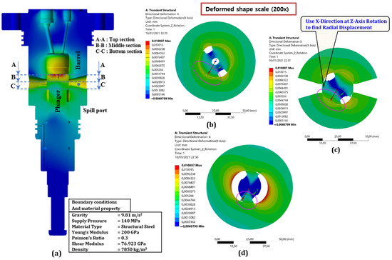
Figure 6.
Displacement dimension on three sections: (a) three-section axial position, (b) distortion of the top section, (c) distortion of the middle section, and (d) distortion of the bottom section.
Additionally, the displacement changes in the five different grid numbers have the same value for grid numbers 4 and 5, which is 0.00266 mm. The fluid–solid thermal solution is thus obtained in the model using a grid number of 14,363,772 to maximize simulation time efficiency. The fluid flow generates pressure and temperature loading in unidirectional fluid-solid thermal coupling. These loadings are used as boundary parameters in the solid mechanic’s equation. The plunger displacement was evaluated using a fluid–solid coupling model and compared to the reference result for validation [7].
3. Results
In this study, the authors used 3D numerical models of the thermal fluid–solid interaction and 1D AMESim modeling for flow rate characteristics. Figure 6a shows the three regions in which the plunger and barrel deformations are examined. Figure 6b–d illustrates the deformation in the top, middle, and bottom parts (enlargements 200 times). A displacement is a number that represents the dislocation to stem clearance in the plunger. Because the study was conducted without clearance circumstances, overlapping regions imply a loss in clearance. Given that the primary directions of the plunger and the barrel are virtually perpendicular to one another, and that the spill port of the barrel has a substantial impact on deformation, the deformation of the plunger in the middle section is fundamentally distinct from that of the barrel.
According to Figure 7, the maximum interference (overlapping region) radial displacement was 0.0008 mm. It occurred between the plunger’s middle section and the barrel’s middle section when the circumferential angle was 10 degrees.
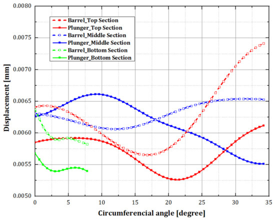
Figure 7.
Comparison of the displacement of the plunger and the barrel with three different sections based on the original dimensions.
The highest decrease in clearance corresponds to the most displacement in the stem section. Table 5 shows the remarkable dimensionless subtraction in the head and stem parts. Because the clearance should be larger than the maximal clearance decrement to prevent metal-to-metal contact between the plunger and the barrel due to deformation, the highest clearance reduction was utilized as a limit value when designing the clearance. The fuel pump clearance was determined after determining that the machining limit for the clearance was between 6 and 9 μm. Figure 8a measures the plunger displacement in the stem. Figure 8b displays comparable tendencies. The current study found The plunger stem’s most significant radial displacement, which found that the value was 0.0031 mm, 11 mm down from the top of the plunger stem. This indicates that the displacement from the current model is better than the previous model [7] for minimizing the metal contact between the barrel and plunger in the high-pressure pump.
Table 5.
Maximum clearance reduction.
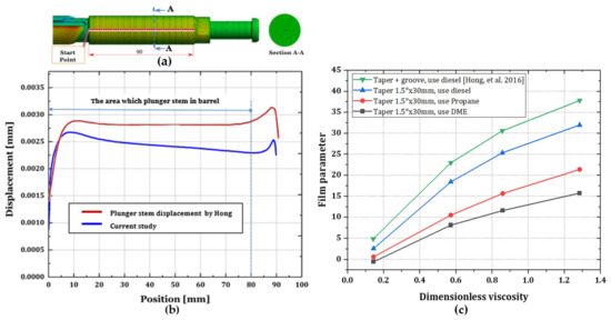
Figure 8.
Displacement measurements: (a) measuring the displacement of the plunger in the stem, (b) comparing the displacement of the plunger stem in the simulation result of Hong [7] for validation, (c) a comparison of present modified taper geometries of the plunger stem using three kinds of fuels on film parameters against dimensionless viscosity with reference study conducted by Hong et al. [5].
In the case of modified dimensionless geometries, Figure 8c depicts the film parameter as a function of dimensionless viscosity with three different fuels compared with groove types, as conducted by Hong et al. [5]. In the case of shallow grooving, the film parameter of diesel fuel was more significant than in the case of propane and DME fuels. Due to the film parameter of the case with no groove applied, the percentage rise in the film parameter was obtained.
The influence of temperature and viscosity parameters on the fuel can affect the fluid flow performance and the heat distribution rate in a material. In addition, fluid velocity can affect the heat distribution rate for the barrel and plunger. Figure 9a–c gives information regarding imported body temperature from ANSYS-Fluent® coupled with ANSYS-Static Structural® using a thermal fluid–solid interaction method.
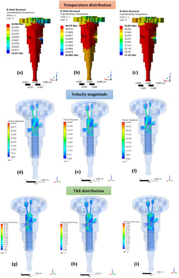
Figure 9.
Barrel and plunger temperature fields, velocity magnitude, and TKE distribution use three different fuels: diesel fuel (a,d,g), propane (b,e,h), and DME fuels (c,f,i).
There are several types of fluid flow, including laminar flow, transitional flow, and turbulent flow. Three factors influence the state of flow analysis (as quantified by the Reynolds number), namely, the viscosity of the liquid (µ), the density of the liquid (ρ), and the diameter of the pipe or orifice (D). Figure 9d–f illustrates the velocity magnitude contour using three fuels. The initial conditions of this simulation include an inlet pressure of 200 bar and an inlet velocity of 5 m/s. The velocity magnitudes for all fuels were higher in the small orifices of the barrel, which was confirmed by the continuity equation. In addition, the density and viscosity of fluid (fuels) can also affect the flow velocity of fuels. In turbulent flow, the flow’s kinetic energy is described in terms of variations in the fluid flow rate velocity about its steady-state (or mean) flow rate.
Figure 9g–i illustrates the results of comparing turbulence kinetic energy using three different fuels. These show that accurate starting TKE descriptions are critical for accurately predicting flows in CFD simulations, particularly in high Reynolds number simulations. Figure 9g shows the turbulence kinetic energy contour in the barrel cylinder for diesel fuel. Here, the high value of TKE occurs explicitly in the region after the inlet port and the upper part of the plunger head. These results suggest that there is not much difference between using propane or DME fuels.
The results of configuring a high-pressure pump with one injector unit using AMESim are shown in Figure 10, Figure 11 and Figure 12. The test values obtained by comparing different plunger diameters and mean flow rates for the configured simulation in AMESim are illustrated in Figure 5b.
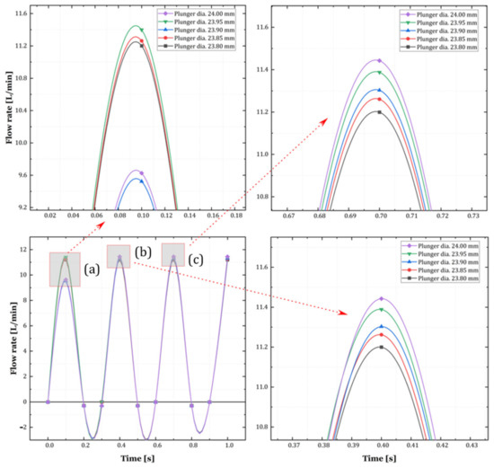
Figure 10.
The flow rate of diesel fuel with different plunger diameters at 2000 RPM.
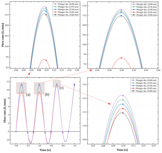
Figure 11.
The flow rate of propane fuel with different plunger diameters at 2000 RPM.
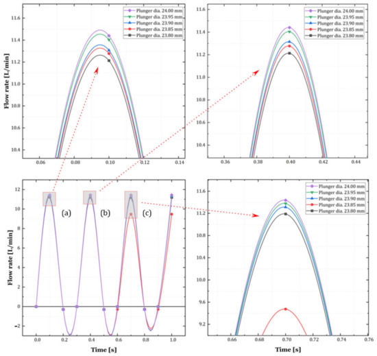
Figure 12.
The flow rate of DME fuel with different plunger diameters at 2000 RPM.
Changes in the diesel fuel flow rate according to the plunger diameter at 2000 RPM can be seen in Figure 10. The initial time has a significant flow rate from 0.0 to 0.1 s. The highest flow rate of around 11.40 L/min was associated with a plunger diameter of 23.95 mm (Figure 10a). On the other hand, the lowest flow rate peak was observed for a plunger diameter of 23.90 mm, with a quantity difference of about 1.9 L. Figure 10b,c depicts a similar trend in which the lowest peak is associated with the smallest plunger diameter (28.80 mm), and the highest peak is associated with the largest plunger diameter of 24.00 mm. On the other hand, negative results indicated reverse fuel flows due to back pressure occurring in the fuel line chamber. Moreover, the fuel flow rate was stable with time due to the fuel supply from the high-pressure pump.
4. Discussion
The present investigation aims to examine the impact of diesel, propane, and DME fuels on the deformation of the plunger barrel and the flow rate characteristics. The analysis involves comparing the displacement of the barrel and plunger concerning the working pressure. Based on the multi-field coupling theory, a 3D numerical model of fluid-–solid- thermal coupling was developed to characterize active deformation and clearance fluctuations. The distinct deformation patterns exhibited by the two components necessitate the independent establishment of suitable clearance for the pump’s head and stem. Additionally, for 1D modeling, the important AMESim parameters were utilized to compare and validate the discharge flow rates of three different fuels concerning their flow rate characteristics. Furthermore, for detail, results will be discussed in the sub-section with some relevant literature.
4.1. Effect of Fuel Pressure on Plunger Deformation
According to the data results of this study, the displacement in the fuel pump was quantitatively analyzed to obtain the most significant decrease in clearance in Figure 6c, which displays the dimensional displacement at the middle section of the barrel and that at the plunger line. Because the barrel and plunger distortion in the center portion is more significant than in the other sections, deformation is only analyzed in the middle line of the head, which is quite similar to a previous study [7]. The dashed line indicates barrel displacement, whereas the solid line indicates plunger displacement. When the barrel and plunger are in a concentric condition with no deformation, the displacement dimension in the y-direction depends on the plunger’s and barrel’s cross-sectional center.
4.2. The Effect of Taper and Clearance of Plunger Stem on Film Parameters
Regarding the hydrodynamic lubrication study, a plunger stem with a tapered 1.5° × 30 mm for diesel fuel improved lubrication properties more effectively for low-viscosity situations than propane and DME fuels. This is because pressure imbalance alleviation provided by the grooves is less efficient in high-viscosity cases due to increased viscous friction. Moreover, increasing the number of film parameters prevents contact friction between the barrel and plunger surfaces and can reduce the wearing and improve the lifetimes of components. This result can be compared with the literature study by Hong et al. [5], which added a circumferential groove and a tapered model to the plunger to increase the pump’s lubricating properties. The authors disregard circumferential grooves with modest depths due to the cost of processing and the reduced capacity to catch wear particles. The grooves’ width and depth are at least 200 times larger than the clearance. Because tapering the bottom section of the stem does not influence the pump’s lubricating qualities, the authors considered tapering the top part of the stem. Several fuel oils are employed in medium-speed diesel engines, and the pump is used in different viscous situations.
4.3. The Thermal Effect, Fluid Velocity, and Turbulence Kinetic Energy of the Fuel Pump
Figure 9a–c depicts the temperature contour distribution on the barrel and plunger using three fuel variations. The figures show higher temperatures were observed on the inlet barrel and plunger surfaces, and lower temperatures were observed at the spill port and outlets. This implies that fuel leaking from the high-pressure side to the low-pressure side will cause a significant increase in temperature. This behavior might be explained by energy conversion. As the fuel temperature rises, its viscosity decreases, resulting in greater leakage rates as compared with another study conducted by Qian et al. [39].
Increasing the turbulent kinetic energy can significantly affect the velocity performance of injection fuel systems, especially in terms of the kinetic energy of fuel molecules. We also noted that TKE values were related to the velocity value (see Figure 9d–f). The computational results are consistent with prior reference studies [40,41,42], with the most variances occurring for the lowest pressure drop levels. This discovery is consistent with primary research to determine the variables influencing the flow through an orifice to exchange heat with the surroundings.
4.4. Effect of Both Differences in Fuels and Plunger Diameters on the Flow Rate Characteristics of the Fuel Pump
The significant differences are the flow rate curve start time, which changes from 0.1 to 0.4 s. The lowest flow rate was about 9.5 L/min with a plunger diameter of 23.85 mm, as validated by a reference study by Wang et al. [38]. Furthermore, the curves were stable after 0.6 s, with a result proportional to the diameter of the plunger, resulting in a higher propane flow rate. On the other hand, adverse effects revealed that there are reverse flows of fuel that occur in the fuel line chamber due to back pressure.
The flow rate of DME fuel at 2000 RPM with various plunger diameters is shown in Figure 12. The flow characteristics of DME fuel were slightly different compared to diesel and propane. In this case, DME fuel showed flow stability initially (from 0.0 to 0.4 s). After that, it experienced a change in flow stability, especially when using a plunger diameter of 23.85 mm. This means there is a volume loss due to backpressure and the differences in the properties of DME fuel compared to diesel and propane fuels.
4.5. The Influence of Fuel Type on Performance Requirements, Environmental Concerns, and Economic Considerations
Fuel choice depends on various factors, including the specific application, performance requirements, environmental concerns, and economic considerations. From a thermal perspective, diesel fuel generally has higher energy density and combustion efficiency than propane and DME, making it an attractive option for high-performance engines. However, propane and DME have lower emissions of particulate matter and nitrogen oxides, which makes them more environmentally friendly. Regarding mechanical aspects, diesel fuel has higher lubricity than propane and DME, which helps reduce wear and tear on engine components such as the fuel injection system, pistons, and cylinder walls, as proven by current and reference studies conducted by Hong et al. [5].
On the other hand, propane and DME have lower corrosivity than diesel fuel, which could extend engine components’ lifespan. Other aspects that must be considered include availability, cost, and infrastructure requirements. Diesel fuel has a well-established infrastructure and is widely available, making it an attractive option for many applications. Propane and DME, on the other hand, may require additional infrastructure investments to enable widespread adoption. The cost of each fuel can vary depending on location and supply, which can impact the economic viability of each option. In summary, the choice of fuel type depends on various factors, and there is no clear winner among the three options. The optimal fuel choice will depend on the user’s specific application, priorities, and considerations.
5. Conclusions
This study used computational modeling to look at the internal workings of a fuel injection pump for a medium-speed marine diesel engine and to determine the flow rate characteristics. These conclusions can be derived from the findings of this investigation. Based on the numerical analysis of the thermal fluid–solid interaction, the maximum interference displacement was 0.0008 mm between the plunger’s middle and middle barrel sections at 10 degrees of circumferential angle. This means the plunger’s middle section receives the highest-pressure distribution from the plunger’s top, bottom, and helical groove. The maximum displacement for the plunger stem was 0.00266 mm at 7.5 mm from the top of the stem, which was 6.94% lower than the literature result.
The effect of a modified plunger stem with a 1.5° × 30 mm taper for lubricity characteristics with three different fuels significantly improved the film parameter and clearance between the plunger and barrel. Geometry optimization is required for determining practical fuel injection pump configurations. Furthermore, adding taper and clearance can prevent metal-to-metal contact, which produces friction, wears on the surface, and damages the components over time. Further, improving the fuel injection velocity to the injector sub-systems is essential. In addition, TKE plays a significant role in fuel velocity to enhance the kinetic energy of the fuel molecules before delivering fuel to the common rail high-pressure pump and injectors.
Moreover, simulation results of different fuel types in AMESim have varied characteristics, and the change in plunger diameter significantly influences the fuel flow rate. DME fuel showed flow stability initially (from 0.0 to 0.4 s) when using a plunger diameter of 23.85 mm. The flow rate of the pump increases if the plunger diameter is increased. Finally, to sum up, new plunger stem design and alternative fuels such as propane and DME are appropriate and recommended for future marine fuel injection pump systems to be more environmentally friendly.
Author Contributions
Conceptualization, Writing—original draft, Methodology, Investigation, Data curation, Formal analysis, B.B.; Funding acquisition, Supervision, Project administration, writing—review and editing, O.L. All authors have read and agreed to the published version of the manuscript.
Funding
The authors are appreciative of the funding they received from the “Regional Innovation Strategy (RIS)” through the National Research Foundation of Korea (NRF), funded by the Ministry of Education (MOE) (2021RIS-003). The national standard power improvement project funded this research, which was supported by the Korea Evaluation Institute of Industrial Technology (KEIT, Korea) (20006864, project name: The Standardization of Quantity Measurement System for LNG Fueled Vessel with Truck-to-Ship Bunkering).
Institutional Review Board Statement
Not applicable.
Informed Consent Statement
Not applicable.
Data Availability Statement
Not applicable.
Acknowledgments
The authors appreciate the anonymous reviewers for their constructive comments and suggestions that significantly improved the quality of this manuscript.
Conflicts of Interest
The authors declare no conflict of interest.
Nomenclature
| Abbreviation | |
| CFD | Computational fluid dynamics |
| CPU | Central processing unit |
| DME | Dimethyl ether |
| FEM | Finite element method |
| RAM | Random access memory |
| RPM | Revolution per minutes |
| TKE | Turbulence kinetic energy |
| Symbols | |
| c | Clearance (mm) |
| Cp | Specific heat at constant pressure (J/kg·°C) |
| d | Displacement (mm) |
| e | Eccentricity (mm) |
| F | Force (N) |
| g | Gravitational acceleration (m·s−2) |
| H | Dimensionless film thickness |
| Hm | |
| k | Heat conductivity coefficient (W/m°C) |
| Mo | Moment at point O |
| P | Supply pressure (MPa) |
| R | Dimensionless plunger radius |
| Rq | Root mean square deviation |
| Rq1 | Root mean square deviation of plunger |
| Rq2 | Root mean square deviation of barrel |
| ∆t | Time interval (s) |
| Ε | Eccentricity ratio (e/c) |
| T | Temperature (°C) |
| t | Time (s) |
| ° | Degree |
| Q | Mean flow rate (L/min) |
| µ | Fluid viscosity (Pa·s) |
| ρ | Density (kg/m3) |
| v | Velocity vector (m/s) |
| α | Thermal expansion coefficient of (/°C) |
| λ | Film parameter |
References
- Wang, Z.; Hu, S.; Ji, H.; Wang, Z.; Liu, X. Analysis of lubricating characteristics of valve plate pair of a piston pump. Tribol. Int. 2018, 126, 49–64. [Google Scholar] [CrossRef]
- Bejger, A.; Drzewieniecki, J.B. The use of acoustic emission to diagnosis of fuel injection pumps of marine diesel engines. Energies 2019, 12, 4661. [Google Scholar] [CrossRef]
- Wang, G.; Zhong, L.; He, X.; Lei, Z.; Hu, G.; Li, R.; Wang, Y. Dynamic behavior of reciprocating plunger pump discharge valve based on fluid structure interaction and experimental analysis. PLoS ONE 2015, 10, e0140396. [Google Scholar] [CrossRef]
- Lan, Q.; Bai, Y.; Fan, L.; Gu, Y.; Wen, L.; Yang, L. Investigation on fuel injection quantity of low-speed diesel engine fuel system based on response surface prediction model. Energy 2020, 211, 118946. [Google Scholar] [CrossRef]
- Hong, S.H.; Lee, B.; Cho, Y. Improvement of lubrication characteristics in the reciprocating fuel pump of marine diesel engines. J. Mech. Sci. Technol. 2016, 30, 5225–5232. [Google Scholar] [CrossRef]
- Bejger, A.; Drzewieniecki, J.B. A new method of identifying the limit condition of injection pump wear in self-ignition engines. Energies 2020, 13, 1601. [Google Scholar] [CrossRef]
- Hong, S.H. A New Clearance Design Method for Reciprocating Fuel Pumps of Medium-Speed Diesel Engines. Tribol. Trans. 2018, 61, 773–783. [Google Scholar] [CrossRef]
- Wang, Q.; Yao, H.; Yu, Y.; Yang, J.; He, Y. Establishment of a real-time simulation of a marine high-pressure common rail system. Energies 2021, 14, 5481. [Google Scholar] [CrossRef]
- Bao, H.-y.; Wang, C.-l.; Lu, F.-x. Temperature impact analysis of star gear bearing inner ring based on under-race lubrication passage. J. Mech. Sci. Technol. 2020, 34, 5271–5278. [Google Scholar] [CrossRef]
- Zhao, B.; Dai, X.D.; Zhang, Z.N.; Xie, Y.B. Numerical study of the effects on clearance joint wear in flexible multibody mechanical systems. Tribol. Trans. 2015, 58, 385–396. [Google Scholar] [CrossRef]
- Hong, S.H. A literature review of lacquer formation in medium-speed and low-speed engines. J. Mech. Sci. Technol. 2016, 30, 5651–5657. [Google Scholar] [CrossRef]
- Hong, S.-H. Improvement of Lubrication Characteristics in Fuel Injection Pump for Medium-Speed Diesel Engines: Part I-Application of Profile Shape. J. Korean Soc. Tribol. Lubr. Eng. 2015, 31, 205–212. [Google Scholar] [CrossRef]
- Lei, D.; Huang, X.; Zhang, H.; Yao, M.; Chen, R.; Liu, J. Optimization and Application of Reciprocating Direct-Drive Electric Submersible Plunger Pump Lifting System in the Xinjiang Oilfield. Open Chem. Eng. J. 2019, 13, 68–80. [Google Scholar] [CrossRef]
- Hong, S.H. Application of Spiral Grooves in Fuel Pump for Medium-Speed Diesel Engines. Tribol. Trans. 2018, 61, 532–538. [Google Scholar] [CrossRef]
- Borghi, M. Hydraulic locking-in spool-type valves: Tapered clearances analysis. Proc. Inst. Mech. Eng. Part I J. Syst. Control. Eng. 2005, 215, 157–168. [Google Scholar] [CrossRef]
- Ma, X.; Wang, Q.J.; Lu, X.; Mehta, V.S. A transient hydrodynamic lubrication model for piston/cylinder interface of variable length. Tribol. Int. 2018, 118, 227–239. [Google Scholar] [CrossRef]
- Xiang, C.; Guo, F.; Jia, X.; Wang, Y.; Huang, X. Thermo-elastohydrodynamic mixed-lubrication model for reciprocating rod seals. Tribol. Int. 2019, 140, 105894. [Google Scholar] [CrossRef]
- Dhar, S.; Vacca, A. A novel FSI–thermal coupled TEHD model and experimental validation through indirect film thickness measurements for the lubricating interface in external gear machines. Tribol. Int. 2015, 82, 162–175. [Google Scholar] [CrossRef]
- Van Emden, E.; Venner, C.H.; Morales-Espejel, G.E. A challenge to cavitation modeling in the outlet flow of an EHL contact. Tribol. Int. 2016, 102, 275–286. [Google Scholar] [CrossRef]
- Venner, C.H.; Wang, J.; Lubrecht, A.A. Central film thickness in EHL point contacts under pure impact revisited. Tribol. Int. 2016, 100, 1–6. [Google Scholar] [CrossRef]
- Masjedi, M.; Khonsari, M.M. An engineering approach for rapid evaluation of traction coefficient and wear in mixed EHL. Tribol. Int. 2015, 92, 184–190. [Google Scholar] [CrossRef]
- Meng, F.M.; Zhang, L.; Liu, Y.; Li, T.T. Effect of compound dimple on tribological performances of journal bearing. Tribol. Int. 2015, 91, 99–110. [Google Scholar] [CrossRef]
- Li, Y.; Ji, Z.; Yang, L.; Zhang, P.; Xu, B.; Zhang, J. Thermal-fluid-structure coupling analysis for valve plate friction pair of axial piston pump in electrohydrostatic actuator (EHA) of aircraft. Appl. Math. Model. 2017, 47, 839–858. [Google Scholar] [CrossRef]
- Najjari, M.; Guilbault, R. Formula derived from particle swarm optimization (PSO) for optimum design of cylindrical roller profile under EHL regime. Mech. Mach. Theory 2015, 90, 162–174. [Google Scholar] [CrossRef]
- Xu, Q.; Liu, L.; Feng, J.; Qiao, L.; Yu, C.; Shi, W.; Ding, C.; Zang, Y.; Chang, C.; Xiong, Y.; et al. A comparative investigation on the effect of different nanofluids on the thermal performance of two-phase closed thermosyphon. Int. J. Heat Mass Transf. 2020, 149, 119189. [Google Scholar] [CrossRef]
- Zhou, T.; Zhao, Y.; Rao, Z. Fundamental and estimation of thermal contact resistance between polymer matrix composites: A review. Int. J. Heat Mass Transf. 2022, 189, 122701. [Google Scholar] [CrossRef]
- Gong, S.; Li, X.; Sheng, M.; Liu, S.; Zheng, Y.; Wu, H.; Lu, X.; Qu, J. High Thermal Conductivity and Mechanical Strength Phase Change Composite with Double Supporting Skeletons for Industrial Waste Heat Recovery. ACS Appl. Mater. Interfaces 2021, 13, 47174–47184. [Google Scholar] [CrossRef]
- Xu, Q.; Wang, K.; Zou, Z.; Zhong, L.; Akkurt, N.; Feng, J.; Xiong, Y.; Han, J.; Wang, J.; Du, Y. A new type of two-supply, one-return, triple pipe-structured heat loss model based on a low temperature district heating system. Energy 2021, 218, 119569. [Google Scholar] [CrossRef]
- Xu, Q.; Feng, J.; Zhang, S. Combined effects of different temperature and pressure loads on the “L”-type large-diameter buried pipeline. Int. J. Heat Mass Transf. 2017, 111, 953–961. [Google Scholar] [CrossRef]
- Xu, Q.; Zou, Z.; Chen, Y.; Wang, K.; Du, Z.; Feng, J.; Ding, C.; Bai, Z.; Zang, Y.; Xiong, Y. Performance of a novel-type of heat flue in a coke oven based on high-temperature and low-oxygen diffusion combustion technology. Fuel 2020, 267, 117160. [Google Scholar] [CrossRef]
- Ding, B.; Feng, W.C.; Fang, J.; Li, S.Z.; Gong, L. How natural convection affect cooling performance of PCM heat sink. Int. J. Heat Mass Transf. 2022, 184, 122272. [Google Scholar] [CrossRef]
- Launder, B.E.; Spalding, D.B. The Numerical Computation of Turbulent Flows. In Numerical Prediction of Flow, Heat Transfer, Turbulence and Combustion; Elsevier: Amsterdam, The Netherlands, 1983; pp. 96–116. [Google Scholar] [CrossRef]
- Bardina, J.E.; Huang, P.G.; Coakley, T.J. Turbulence Modeling Validation, Testing, and Development. 1997. Available online: https://ntrs.nasa.gov/citations/19970017828 (accessed on 20 September 2022).
- Canonsburg, T.D. ANSYS Fluent Tutorial Guide; ANSYS: Canonsburg, PA, USA, 2013; Volume 15317, pp. 724–746. [Google Scholar]
- Shih, T.H.; Liou, W.W.; Shabbir, A.; Yang, Z.; Zhu, J. A new k-ϵ eddy viscosity model for high reynolds number turbulent flows. Comput. Fluids 1995, 24, 227–238. [Google Scholar] [CrossRef]
- Memon, A.A.; Sheikh, S.; Siddique, M.; Ishtiyaque, S. Di-Methyl Ether (DME) Prospective in Terms of Conventional Fuels in Pakistan from Gasification of Aboriginal Coal Di-Methyl Ether (DME) Prospective in Terms of Conventional Fuels in Pakistan from Gasification of Aboriginal Coal. J. Appl. Emerg. Sci. 2018, 7, 156–165. [Google Scholar]
- Hayer, F.; Bakhtiary-Davijany, H.; Myrstad, R.; Holmen, A.; Pfeifer, P.; Venvik, H.J. Synthesis of dimethyl ether from syngas in a microchannel reactor-Simulation and experimental study. Chem. Eng. J. 2011, 167, 610–615. [Google Scholar] [CrossRef]
- Wang, H.P.; Zheng, D.; Tian, Y. High pressure common rail injection system modeling and control. ISA Trans. 2016, 63, 265–273. [Google Scholar] [CrossRef]
- Qian, D.; Liao, R.; Xiang, J.; Sun, B.; Wang, S. Thermal fluid-structure interaction analysis on the piston/cylinder interface leakage of a high-pressure fuel pump for diesel engines. Proc. Inst. Mech. Eng. Part J J. Eng. Tribol. 2017, 231, 791–798. [Google Scholar] [CrossRef]
- Kacem, S.H.; Jemni, M.A.; Driss, Z.; Abid, M.S. The effect of H2 enrichment on in-cylinder flow behavior, engine performances and exhaust emissions: Case of LPG-hydrogen engine. Appl. Energy 2016, 179, 961–971. [Google Scholar] [CrossRef]
- Aditya Wardana, M.K.; Lim, O. A study effects of injection pressure and wall temperature on the mixing process of NOx and NH3 in Selective Catalytic Reduction system. J. Mechatron. Electr. Power Veh. Technol. 2020, 11, 45. [Google Scholar] [CrossRef]
- Yosri, M.R.; Ho, J.Z.; Meulemans, M.; Talei, M.; Gordon, R.L.; Brear, M.J.; Cosby, D.; Lacey, J.S. Large-eddy simulation of methane direct injection using the full injector geometry. Fuel 2021, 290, 120019. [Google Scholar] [CrossRef]


Disclaimer/Publisher’s Note: The statements, opinions and data contained in all publications are solely those of the individual author(s) and contributor(s) and not of MDPI and/or the editor(s). MDPI and/or the editor(s) disclaim responsibility for any injury to people or property resulting from any ideas, methods, instructions or products referred to in the content. |
© 2023 by the authors. Licensee MDPI, Basel, Switzerland. This article is an open access article distributed under the terms and conditions of the Creative Commons Attribution (CC BY) license (https://creativecommons.org/licenses/by/4.0/).