Abstract
Renewable Energy Sources (RES) are widely used worldwide due to their positive effect on the environment, being sustainable, low cost, and controllable. The power generated from RESs must be configured to interface and perfectly synchronize with the grid by using Power Electronics Converters (PEC). A Phase-Locked Loop (PLL) is one of the most popular synchronization techniques used due to its speed and robustness. A growing issue that results in oscillations in the estimated fundamental grid phase, frequency, and voltage amplitude is the DC-offset in the input of the PLL. This study was developed to eliminate the DC-offset in the single-phase grid synchronization using Delay Signal Cancellation (DSC) and a fixed-length Transfer Delay (TD)-based PLL. Then, the small-signal model, stability analysis, and selection of controller gains were discussed. The proposed PLL was simulated using MATLAB/Simulink. Moreover, to evaluate the proposed method, several scenarios were developed in order to compare it with other powerful PLLs in terms of performance indicators such as settling time, frequency, and phase error. As a result, the proposed PLL has the fastest dynamic response, completely rejects the DC-offset effect, and fully synchronizes with the electrical grid.
1. Introduction
Renewable Energy Sources (RES) such as wind energy, solar energy, and hydro energy are widely used due to their positive effects on the environment, being sustainable, low cost, and controllable [1]. According to the International Energy Agency (IEA), the world generated about 20% of its total energy in 2010 from RESs, and the total generation in 2020 from RESs is 28% [2]. This is a positive indicator that the world is moving steadily to make the most of sustainable resources.
The power generated from RESs must be shaped in order to be interfaced with the grid by employing Power Electronics Converters (PEC) [3]. In grid-connected RES systems, the most popular synchronization technique is based on Phase-Locked Loops, (PLL) which synchronize the output power from the PEC with the electrical grid [4,5,6,7,8].
The Synchronous Reference Frame (SRF) PLL is one of the most popular PLLs. SRF-PLLs have three main parts. The first is the Phase Detector (PD), which generates a phase error signal, i.e., a signal that contains the error between actual and estimated phases.
The second and third parts of SRF-PLLs are the Loop Filter (LF) and the Voltage-Controlled Oscillator (VCO) [8]. The LF is a Proportional Integrator (PI) controller that is mainly responsible for suppressing disturbances inside the PLL control loop. The output from the LF moves through VCO to estimate the grid phase under any conditions.
To properly match the grid synchronization, problems caused by the presence of DC-offset in the PLL’s input must be overcome. The existence of oscillations in the estimated fundamental frequency, phase, and amplitude is only one of many difficulties. However, the stability of the closed-loop system can be compromised. The DC-offset in grid-connected PECs can be caused by a variety of factors, including the usage of A/D conversions, digital controllers, the use of control algorithms in microcontrollers, sensor offsets, geomagnetic events, and grid failures [4,9,10,11,12,13,14].
In general, single-phase PLLs are more difficult to construct than three-phase PLLs because of the way to generate orthogonal signals are generated in the PD part of the PLL. Many techniques have been proposed in order to generate the orthogonal signal in the single-phase PLL [15,16,17,18,19,20].
In ref. [16], the authors conducted a comprehensive comparison of seven orthogonal signal generator structures, considering five assessment criteria. Their analysis revealed that Transfer Delay (TD) and all-pass filters are the simplest approaches to generating an orthogonal signal. However, the Hilbert Transform (HT) and Complex Coefficient Filter (CCF) are more complicated due to the additional compensation structure required. Inverse park transformation, Second-Order Generalized Integrator (SOGI), and CCF exhibit inherent filtering characteristics and offer better steady-state accuracy. In contrast, TD requires lower filter design criteria.
To solve the DC-offset effect in the PLL’s input, the authors in [9] proposed a novel PLL architecture that comprises three key components: a filter-based Fundamental Positive Sequence Component Separator (FPSCS), an SRF-PLL, and a Secondary Control Path (SCP). The FPSCS module employs a Sliding Goertzel Discrete Fourier Transform (SGDFT) filter and the symmetrical component method to accurately isolate the FPSC, even in the presence of distortion. Additionally, the FPSCS part can remove the effect of the DC-offset in the PLL inputs.
The authors in [4] employed a DC-immune operator as a straightforward and efficient method to eliminate the influence of DC-offset on a three-phase PLL input. Additionally, they incorporated a phase error compensator to eliminate the phase shift effect in the PLL’s output.
In ref. [13], the authors introduced an innovative method known as Enhanced Delayed Signal Cancellation (EDSC) for integrating distributed RESs into the power grid, which can be seamlessly integrated into a conventional Cascaded Delayed Signal Cancellation (CDSC) PLL, enabling it to function as a reliable grid synchronization tool for grid-connected converters and to remove the effect of the DC-offset. The approach demonstrates the capability of estimating both positive and negative sequences of the fundamental frequency, ensuring a fast settling time and significantly enhancing the synchronization process. However, it is essential to note that this method does not incorporate any representation of the small-signal model.
Another investigation presented various techniques for rejecting DC-offset in three-phase grid synchronizations [12]. These approaches encompass PLLs that utilize Delayed Signal Cancellation (DSC) operators within dq and αβ reference frames.
In ref. [21], the authors proposed applying the Modified Delayed Signal Cancelation (MDSC) operator in the dq reference frame to reject the DC-offset effect, regardless of the delay factor selection.
For single-phase grid synchronization, Golestan et al. (2019) proposed PLLs based on adaptive and non-adoptive CDSC [22]. Each DSC operator can reject disturbances in a particular way. A delay length equal to one-half of the fundamental grid period was employed for DC-offset reduction. Moreover, the Orthogonal Signal Generation (OSG) required for transformation was created by delaying the initial single-phase signal by 90°, and the orthogonal signal is produced.
In [23], a closed-loop control two-phase generator was integrated into the SRF-PLL to eliminate DC-offset. The method involves computing the difference between the input and the extracted α-axis component, then passing it through an integrator. Finally, the output representing the input DC component was subtracted from the input signal.
In ref. [24], a frequency-fixed Cascaded Generalized Integrator (CGI) PLL was proposed to eliminate the DC-offset in the PLL’s input. The α-axis output of the first SOGI block serves as input for the second SOGI block. The αβ-axis outputs of the second SOGI block were fed to the embedded SRF-PLL. However, the dynamic response and harmonic attenuation capability of the SRF-PLL were influenced by its bandwidth.
The literature on PLL analysis in single-phase grid-connected systems has explored various techniques to enhance the accuracy and stability of the system. One such technique, presented in [11], involves using a Third-Order Generalized Integrator (TOGI) to construct an alpha and beta static coordinate system. This method depends on a virtual orthogonal voltage vector approach that eliminates DC-offset in a voltage signal or zero offset in the sampling process while maintaining consistent signal amplitude. The authors also introduced an adaptive frequency estimation unit to tackle changes in the power grid voltage frequency, thereby ensuring PLL accuracy.
In ref. [10], an improved single-phase Fixed-Frequency PLL (FFPLL) based on the SOGI filter was proposed. This method utilizes the fixed-frequency SOGI filter to effectively eliminate the impact of DC-offset in various ways.
In ref. [14], the authors introduced a novel structure called the Novel Second-Order Generalized Integrator (NSOGI) and a modified version of the NSOGI that includes DC-offset rejection capability.
This study suggests a τ delay time to create a straightforward technique for DC-offset rejection that is not constrained to any particular time delay; this will provide the proposed PLL more flexibility than the PLLs discussed above. The mathematical representation, the small-signal model, and the design of the PI controller’s gains were developed in this work. To evaluate the effectiveness of the proposed PLL, a comparison with existing PLLs was carried out through several scenarios taking into account some indicators such as phase error, estimated frequency, and settling time.
The rest of this paper is organized as follows: Section 2 outlines the methodology. Section 3 presents the fundamental concept, the mathematical representation, the analysis of the small-signal model, the design of the controller gains, and a comparison of the real-time and small-signal models for the proposed PLL. In Section 4, a comparison is made between the proposed PLL and other powerful PLLs using MATLAB/Simulink. Finally, Section 5 concludes with the conclusions.
2. Methodology
A simple and effective method for grid synchronization is proposed. In addition, the proposed method is capable of completely rejecting the DC-offset. Several steps were taken to achieve the objectives of the study:
- Description of the suggested method’s block diagram and real-time mathematical model analysis;
- Mathematically determining the structure of the proposed method’s small-signal model;
- Designing and building a small-signal model’s closed-loop transfer function;
- Utilizing a closed-loop transfer function to calculate the PI controller’s gain;
- Checking the accuracy of the small-signal model;
- Compare the proposed method with other robust methods to evaluate the proposed PLL through several scenarios.
The methodology consists of six main points. Each of these points is discussed in-depth to provide a comprehensive understanding of the research process, with a clear explanation of the steps taken to carry out this study and to ensure that the methodology is transparent.
3. Development
3.1. Proposed PLL
The proposed PLL was created based on TD and DSC operators. Figure 1 presents the real-time block diagram for the proposed PLL. To analyze the system mathematically, the analysis starts with the input signals. Assume that the grid voltage can be represented as:
where is the alpha signal in the -reference frame, is the grid-phase, is the grid-amplitude, is the grid-frequency, φ is the initial phase angle, and is the DC component in the input voltage .
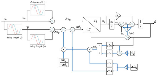
Figure 1.
Proposed Non-adaptive DCI PLL.
According to Figure 1, the orthogonal signal () can be written as:
where T is the time period, , and is the nominal grid frequency. The components of the voltages in Equations (1) and (2) that are delayed can be represented as follows:
where the time delay is expressed in seconds by the symbol τ. The signals are deducted from the delayed version of the signals in the following manner to eliminate the DC-offset:
According to Figure 1, by employing , the adopted phase correction is the actual phase delay caused by utilizing the time delay to cancel the DC-offset in the PLL, and the orthogonal signal is developed to solve the oscillation problem under off-nominal frequency:
Figure 1 shows the proposed PLL. This approach is called a single-phase, non-adaptive DC-immune PLL (non-adaptive DCI PLL). can be written as:
where is the estimated signal. At synchronization and yield . This indicates that is controlled and the error signal is equal to zero. For that, it is necessary to discuss closed-loop stability and create a voltage controller that will regulate the q-axis voltage to zero. The PLL small-signal model is typically used to evolve the PI controller as the voltage controller.
3.2. Small-Signal Model
This section focuses on deriving a small-signal model for the proposed single-phase, non-adaptive DCI PLL. The estimated voltage can be represented as:
In Equation (9), the double frequency terms written in the bold line will cancel one another out near the synchronization condition.
By using trigonometric identities to Equation (10), can be written as:
It is necessary to know that , , and . To evaluate the small-signal model, the following approximation is applicable:
In addition, and can simplified in the small-signal analysis as follows:
Applying the above approximations to Equation (11) yields:
Taking the Laplace transform to Equation (18) yields:
where .
According to Equation (19) and Figure 1, the small-signal model for the proposed non-adaptive DCI PLL is shown in Figure 2.
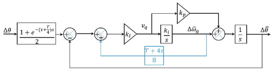
Figure 2.
Small-signal model for the proposed non-adaptive DCI PLL.
According to Figure 2, the closed-loop transfer function can be represented as:
When utilizing estimated signals in a system, it can cause perturbations. Therefore, it is essential to discuss the closed-loop stability and design a voltage controller to regulate the q-axis voltage to zero. Typically, the PI controller is employed as the voltage controller, which is designed based on the small-signal model of the PLL.
3.3. PI Gains Design
In this section, the PI controller gains were calculated using the second-order Characteristic Equation (CE) in Equation (20), in which the small-signal model closed-loop transfer function
where is the natural frequency and is the damping factor, can be used to construct the controller gains.
For the recommended Phase Margin (PM) range of 30° < PM < 60°, the value of b is chosen as . This decision takes into account a damping factor of 0.707 and a desired PM of 45°. In addition, is selected as 40π rad/s, τ = 0.002 s, and V = 1 pu, which yields = 0.618. Thus, the controller gains are ( and ).
The results in Figure 3 show that when a phase jump of 30 degrees is applied to the grid voltage at 0.02 s, the small-signal model and real-time model responses are quite similar, which validates the small-signal model.
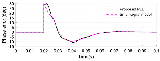
Figure 3.
Proposed non-adaptive DCI PLL and its small-signal model results under a phase jump of 30 degrees.
The proposed single-phase, non-adaptive DCI PLL has the ability to eliminate the impact of DC-offset at any given delay time. To validate its effectiveness across various delay times, a DC-offset of 0.1 pu was intentionally introduced to the grid voltage at 0.02 s. Additionally, a phase jump of 30 degrees was applied to the grid voltage at 0.12 s, as shown in Figure 4a. In Figure 4a, the estimated voltage shown is for τ = 0.005 s.
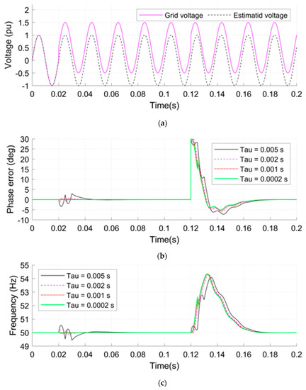
Figure 4.
The influence of different values of τ on the performance of the proposed single-phase DCI PLL under the presence of 0.1 pu DC-offset at 0.02 s and 30 degrees phase jump at 0.12 s: (a) the grid voltage and the estimated voltage for τ = 0.005 s, (b) the phase error for the proposed PLL with different τ delays, (c) the estimated frequency for the proposed PLL with deferent τ delays.
The estimated phase error and frequency for the proposed single-phase, non-adaptive DCI PLL were evaluated under different delay times while considering the presence of a 0.1 pu DC-offset at 0.02 s and a phase jump of 30 degrees at 0.12 s in the grid voltage. The following time delays were chosen: τ1 = 0.005, τ2 = 0.002, τ3 = 0.001, and τ4 = 0.0002. The controller gains were calculated for the selected time delay as follows: for τ1, ( and ); for τ2, ( and ); for τ3, ( and ); and finally, for τ4, ( and ). The simulation results are shown in Figure 4b,c.
The results show that the proposed PLL effectively eliminates the DC-offset within a short duration and allows for the utilization of any time delay without being limited to a specific value, as shown in Figure 4. Additionally, the results indicate that the delay time has a significant impact on the system’s behavior, as shown in Figure 4b,c. The fastest response was observed when a delay time was equal to 0.0002 s. In this scenario, the effect of the DC offset on the estimated phase error and frequency was found to be very small.
4. Results and Discussions
In this part, deferent scenarios were applied by using the MATLAB/Simulink tool to evaluate the performance of the proposed single-phase, non-adaptive DCI PLL with the non-adaptive (see Figure 5) and the adaptive (see Figure 6) single-phase DSC-PLLs [24]. In MATLAB/Simulink, the blocks “Three-Phase Programmable Voltage Source, Three-Phase V-I Measurement, and Three-Phase Series RLC Load” were used to generate the grid signal and introduce a disturbance in the grid voltage.
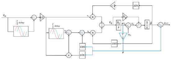
Figure 5.
Non-adaptive DSC PLL.
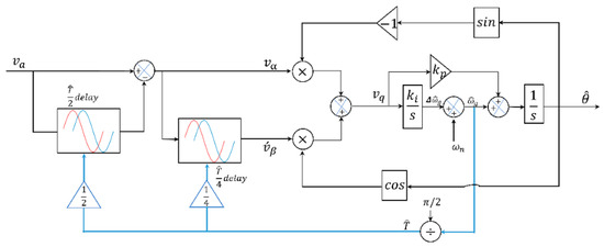
Figure 6.
Adaptive DSC PLL.
To achieve fair comparisons, the PI controller gains for the adaptive and the non-adaptive single-phase DSC-PLLs were designed based on their respective small-signal models using the same ζ and as in the proposed single-phase, non-adaptive DCI PLL. Based on its small-signal model, the single-phase, non-adaptive DSC-PLL PI controller gains are calculated as , , whereas the single-phase adaptive DSC-PLL gains are calculated as , .
The following cases are considered for the comparison:
- Case 1.
- A phase jump of 30 degrees is applied at 0.02 s (see Figure 7a).
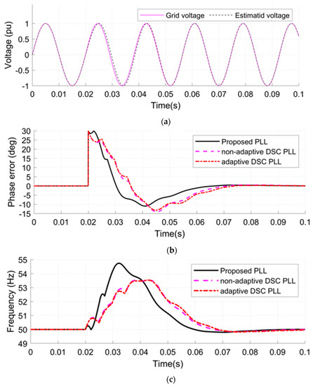 Figure 7. Results under case 1: (a) grid voltage and estimated voltage for the proposed PLL, (b) estimated phase error, (c) estimated frequency.
In this case, with a phase jump of 30 degrees added to the grid voltage, the proposed PLL locked the grid signal in 47 milliseconds (ms) (Figure 7b), while the single-phase, non-adaptive and the single-phase adaptive DSC PLLs required 52.9 ms and 54.9 ms, respectively. The proposed PLL has the fastest synchronization time.
- Case 2.
- A jump in the grid frequency is applied from 50 to 55 Hz at 0.02 s (see Figure 8a).
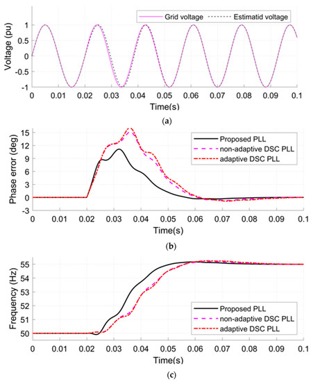 Figure 8. Results under case 2: (a) grid voltage and estimated voltage for proposed PLL, (b) estimated phase error, (c) estimated frequency.
In the second case (Figure 8), the results show that the proposed non-adaptive DCI PLL has the shortest synchronization time when applying a 5 Hz jump in the frequency the phase error becomes zero in 39.10 ms (Figure 8b) while the non-adaptive DCS PLL was 64.70 ms and the single-phase adaptive DCS PLL was 70.00 ms. Moreover, the proposed PLL shows the minimum estimated peak frequency where the peak value of the estimated frequency is 55.16 hertz (Hz) (Figure 8c) while the single-phase, non-adaptive and the single-phase adaptive DSC PLL required 55.20 Hz and 55.24 Hz, respectively.
- Case 3.
- A DC-offset is applied at 0.02 s to the grid voltage with a value of 0.1 pu (see Figure 9a).
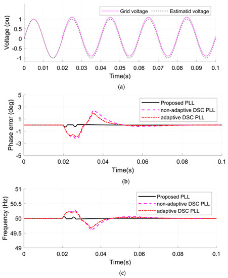 Figure 9. Results under case 3: (a) grid voltage and estimated voltage for proposed PLL, (b) estimated phase error, (c) estimated frequency.
In this case, with a 0.1 pu DC-offset added to the grid voltage, the proposed single-phase, non-adaptive DCI PLL showed the shortest synchronization time, locking the grid signal in 18.90 ms (Figure 9b), compared to 52.80 ms for the non-adaptive DSC PLL and 49.4 ms for the adaptive DSC PLL. The estimated peak frequency for the proposed single-phase PLL was 50.06 Hz (Figure 9c), while the non-adaptive and the adaptive DSC PLL required 49.60 Hz and 49.67 Hz, respectively, so the proposed DCI PLL has the best behavior in this case.
- Case 4.
- A phase jump of 30 degree and a DC-offset of 0.15 Pu are applied to the grid voltage at 0.02 (see Figure 10a).
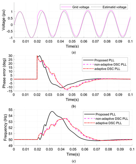 Figure 10. Results under case 4: (a) grid voltage and estimated voltage for proposed PLL, (b) estimated phase error, (c) estimated frequency.
In the fourth case, with a 0.15 pu DC-offset and a phase jump of 30 degrees applied simultaneously to the grid voltage, the proposed single-phase, non-adaptive DCI PLL once again showed the fastest synchronization time, locking the grid signal in 45.60 ms (Figure 10b). Meanwhile, the non-adaptive DSC PLL and the adaptive DSC PLL required 53.00 ms and 56.40 ms, respectively.
- Case 5.
- A jump in the amplitude of the grid voltage from 1 to 1.2 Pu at 0.02 s with a DC-offset applied at the same time as in case 3 (see Figure 11a).
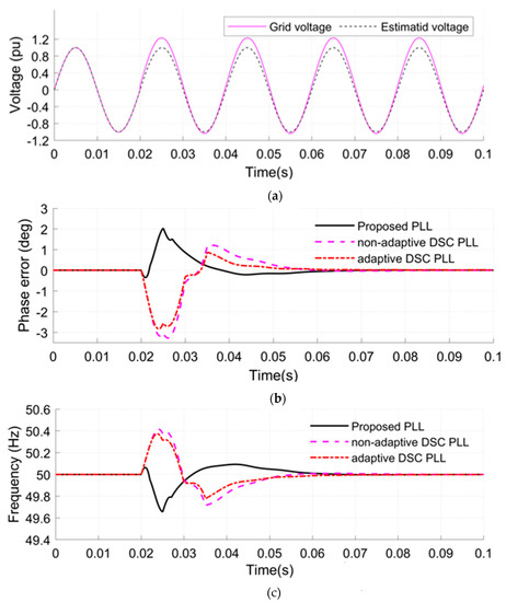 Figure 11. Results under case 5: (a) grid voltage and estimated voltage for proposed PLL, (b) estimated phase error, (c) estimated frequency.
In this case, the results in Figure 11 show that the proposed single-phase, non-adaptive DCI PLL has the shortest synchronization time when a jump in the amplitude of the grid voltage and a DC-offset with value 0.1 pu were applied at 0.02 s. The proposed single-phase, non-adaptive DCI PLL’s phase error becomes zero in 39.20 ms (Figure 11b), while the non-adaptive DSC PLL was 42.10 ms and the single-phase adaptive DSC PLL was 42.90 ms.
- Case 6.
- A jump in the amplitude of the grid voltage from 1 to 1.1 Pu and a DC-offset with a value 0.2 Pu applied at 0.02 s (see Figure 12a).
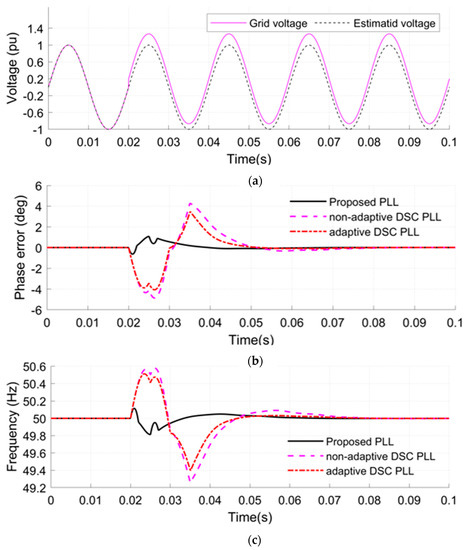 Figure 12. Results under case 6: (a) grid voltage and estimated voltage for proposed PLL, (b) estimated phase error, (c) estimated frequency.
Finally, in the last case, with a 0.2 pu DC-offset and a jump in amplitude from 1 to 1.1 pu applied simultaneously to the grid voltage, the proposed single-phase, non-adaptive DCI PLL showed the shortest synchronization time of 38.10 ms (Figure 12b), while the non-adaptive DSC PLL required 59.20 ms and the adaptive DSC PLL required 55.90 ms. The estimated peak frequency for the proposed PLL was 49.82 Hz (Figure 12c), while the non-adaptive and adaptive DSC PLL required 49.26 Hz and 49.41 Hz, respectively, so the proposed PLL has the best behavior in this case.
The statistical results obtained from the numerical simulations conducted under different scenarios, including phase jumps, frequency variations, amplitude changes, and DC-offsets, clearly demonstrate that the proposed PLL exhibits the fastest transient response, shortest synchronization time, and better dynamic performance compared to other PLLs across nearly all performance indices.
Table 1 summarizes the performance comparisons of the proposed single-phase, non-adaptive DCI PLL with the single-phase, non-adaptive DSC PLL and the single-phase adaptive DSC PLL in terms of phase settling time and the peak estimated frequency.

Table 1.
The synchronization time and the peak estimated frequency for cases one to six.
According to the results in Figure 7, Figure 8, Figure 9, Figure 10, Figure 11 and Figure 12 and Table 1, even though the single-phase, non-adaptive DSC PLL and the single-phase adaptive DSC PLL have a good response, the proposed PLL has the fastest dynamic response with the minimum settling time. Moreover, the proposed single-phase, non-adaptive DCI PLL can eliminate the DC-offset in a very short time (see the third case in Table 1) and utilizing any time delay; that is, it is not restricted to a specific time delay.
5. Conclusions
In this study, a straightforward and effective approach is presented for mitigating the impact of DC-offset during the grid synchronization process. The proposed method involves using a simple single-phase PLL based on the TD technique to generate orthogonal signals and a DSC operator to eliminate the DC-offset effect. This PLL is capable of removing DC-offsets using any time delay, without restrictions. The proposed method contains a phase error compensator operator to solve the phase shift problem caused by the delayed version of the input signals. The research includes a detailed discussion on the mathematical model, small-signal model, closed-loop stability, and design of PI controller gains. The small-signal model was validated by comparing it with a real-time model. The gains of the PI controller were determined by analyzing the real-time and small-signal models. This involved deriving a second-order characteristic equation to represent the system accurately. To evaluate the effectiveness of the proposed technique, various scenarios were simulated using the MATLAB/Simulink tool and compared with other single-phase PLLs in terms of the performance indicators, such as settling time, frequency, and phase error. The scenarios involved introducing different disturbances to the input voltage that include adding phase jumps, introducing DC offsets, changing the grid frequency, and changing the voltage amplitude. The results demonstrate the phase error and estimated frequency for all simulated techniques. In addition, the results show the impact of introducing disturbances in the grid voltage and how the proposed PLL effectively locks onto the signal. Moreover, the results show that the proposed PLL has the fastest dynamic response and shortest settling time, making it a reliable option for grid synchronization. The proposed PLL is expected to be very fruitful from an industrial point of view due to its simplicity and efficiency.
Author Contributions
Conceptualization, M.A.B.I. and P.M.B.B.; methodology, M.A.B.I. and Z.A.A.M.; software, M.A.B.I. and Z.A.A.M.; validation, P.M.B.B. and M.A.B.I.; formal analysis, M.A.B.I.; investigation, M.A.B.I. and P.M.B.B.; resources, M.A.B.I., Z.A.A.M. and P.M.B.B.; data curation, M.A.B.I. and Z.A.A.M.; writing—original draft preparation, M.A.B.I. and Z.A.A.M.; writing—review and editing, M.A.B.I. and P.M.B.B.; visualization, M.A.B.I. and P.M.B.B.; supervision, P.M.B.B.; project administration, P.M.B.B. All authors have read and agreed to the published version of the manuscript.
Funding
This research received no external funding.
Institutional Review Board Statement
Not applicable.
Informed Consent Statement
Not applicable.
Data Availability Statement
Not applicable.
Conflicts of Interest
The authors declare no conflict of interest.
References
- Ray, P. Renewable energy and sustainability. Clean Technol. Environ. Policy 2019, 21, 1517–1533. [Google Scholar] [CrossRef]
- IEA. Global Energy Review 2020; IEA: Paris, France, 2020; Available online: https://www.iea.org/reports/global-energy-review-2020 (accessed on 30 April 2023).
- Can, E. The design and experimentation of the new cascaded DC-DC boost converter for renewable energy. Int. J. Electron. 2019, 106, 1374–1393. [Google Scholar] [CrossRef]
- Smadi, I.A.; Issa, M.B. Phase locked loop with DC-offset removal for grid synchronization. In Proceedings of the IECON 2019-45th Annual Conference of the IEEE Industrial Electronics Society 1, Lisbon, Portugal, 14–17 October 2019; IEEE: Piscataway, NJ, USA, 2019; pp. 4669–4673. [Google Scholar]
- Sahoo, A.; Ravishankar, J.; Jones, C. Phase-locked loop independent second-order generalized integrator for single-phase grid synchronization. IEEE Trans. Instrum. Meas. 2021, 70, 9004409. [Google Scholar] [CrossRef]
- Hamood, M.A.; Marjanovic, O.; Carrasco, J. Adaptive impedance-conditioned phase-locked loop for the VSC converter connected to weak grid. Energies 2021, 14, 6040. [Google Scholar] [CrossRef]
- Herrejón-Pintor, G.A.; Melgoza-Vázquez, E.; Chávez, J.D.J. A Modified SOGI-PLL with Adjustable Refiltering for Improved Stability and Reduced Response Time. Energies 2022, 15, 4253. [Google Scholar] [CrossRef]
- Kathiresan, A.C.; PandiaRajan, J.; Sivaprakash, A.; Sudhakar Babu, T.; Islam, M.R. An adaptive feed-forward phase locked loop for grid synchronization of renewable energy systems under wide frequency deviations. Sustainability 2020, 12, 7048. [Google Scholar] [CrossRef]
- Cao, Y.; Yu, J.; Xu, Y.; Li, Y.; Yu, J. An efficient phase-locked loop for distorted three-phase systems. Energies 2017, 10, 280. [Google Scholar] [CrossRef]
- Stojic, D.; Tarczewski, T.; Niewiara, L.J.; Grzesiak, L.M. Improved fixed-frequency sogi based single-phase PLL. Energies 2022, 15, 7297. [Google Scholar] [CrossRef]
- Du, H.; Sun, Q.; Cheng, Q.; Ma, D.; Wang, X. An adaptive frequency phase-locked loop based on a third order generalized integrator. Energies 2019, 12, 309. [Google Scholar] [CrossRef]
- Golestan, S.; Guerrero, J.M.; Gharehpetian, G.B. Five approaches to deal with problem of DC offset in phase-locked loop algorithms: Design considerations and performance evaluations. IEEE Trans. Power Electron. 2015, 31, 648–661. [Google Scholar] [CrossRef]
- Ahmed, H.; Ushirobira, R.; Efimov, D. Arbitrarily Fast Delayed Signal Cancellation PLL for Grid-Integration of Renewable Energy Sources. IET Renew. Power Gener. 2022. [Google Scholar] [CrossRef]
- Hui, N.; Wang, D.; Li, Y. A novel hybrid filter-based PLL to eliminate effect of input harmonics and DC offset. IEEE Access 2018, 6, 19762–19773. [Google Scholar] [CrossRef]
- Xu, J.; Qian, H.; Bian, S.; Hu, Y.; Xie, S. Comparative study of single-phase phase-locked loops for grid-connected inverters under non-ideal grid conditions. CSEE J. Power Energy Syst. 2020, 8, 155–164. [Google Scholar]
- Gautam, S.; Hassan, W.; Bhatta, A.; Lu, D.D.C.; Xiao, W. A comprehensive study of orthogonal signal generation schemes for single phase systems. In Proceedings of the 2021 1st International Conference on Power Electronics and Energy (ICPEE), Bhubaneswar, India, 2–3 January 2021; pp. 1–8. [Google Scholar]
- Golestan, S.; Guerrero, J.M.; Vasquez, J.C. Single-phase PLLs: A review of recent advances. IEEE Trans. Power Electron. 2017, 32, 9013–9030. [Google Scholar] [CrossRef]
- Xia, T.; Zhang, X.; Tan, G.; Liu, Y. All-pass-filter-based PLL for single-phase grid-connected converters under distorted grid conditions. IEEE Access 2020, 8, 106226–106233. [Google Scholar] [CrossRef]
- Ikken, N.; Bouknadel, A.; Haddou, A.; Tariba, N.E. PLL synchronization method based on second-order generalized integrator for single phase grid connected inverters systems during grid abnormalities. In Proceedings of the 2019 International Conference on Wireless Technologies, Embedded and Intelligent Systems (WITS), Fez, Morocco, 3–4 April 2019; pp. 1–5. [Google Scholar]
- Xia, T.; Zhang, X.; Tan, G.; Liu, Y. Synchronous reference frame single-phase phase-locked loop (PLL) algorithm based on half-cycle DFT. IET Power Electron. 2020, 13, 1893–1900. [Google Scholar] [CrossRef]
- Smadi, I.A.; Atawi, I.E.; Ibrahim, A.A. An Improved Delayed Signal Cancelation for Three-Phase Grid Synchronization with DC Offset Immunity. Energies 2023, 16, 2873. [Google Scholar] [CrossRef]
- Golestan, S.; Guerrero, J.M.; Vasquez, J.C.; Abusorrah, A.M.; Al-Turki, Y. Advanced single-phase DSC-based plls. IEEE Trans. Power Electron. 2019, 34, 3226–3238. [Google Scholar] [CrossRef]
- Lubura, S.; Šoja, M.; Lale, S.A.; Ikić, M. Single-phase phase locked loop with DC offset and noise rejection for photovoltaic inverters. IET Power Electron. 2014, 7, 2288–2299. [Google Scholar] [CrossRef]
- Kulkarni, A.; John, V. Design of a fast response time single-phase PLL with DC offset rejection capability. Electr. Power Syst. Res. 2017, 145, 35–43. [Google Scholar] [CrossRef]


Disclaimer/Publisher’s Note: The statements, opinions and data contained in all publications are solely those of the individual author(s) and contributor(s) and not of MDPI and/or the editor(s). MDPI and/or the editor(s) disclaim responsibility for any injury to people or property resulting from any ideas, methods, instructions or products referred to in the content. |
© 2023 by the authors. Licensee MDPI, Basel, Switzerland. This article is an open access article distributed under the terms and conditions of the Creative Commons Attribution (CC BY) license (https://creativecommons.org/licenses/by/4.0/).