Article

Sustainable Seismic Design of Triple Steel Structures

1
MGA Structural Engineers Inc., 111 N. Jackson St., Glendale, CA 91206, USA
2
International Institute of Earthquake Engineering and Seismology, Tehran 19537-14453, Iran
3
Department of Civil Engineering, Kharazmi University, Tehran 15719-14911, Iran
*
Author to whom correspondence should be addressed.
Sustainability 2023, 15(13), 10336; https://doi.org/10.3390/su151310336
Submission received: 7 April 2023 / Revised: 16 May 2023 / Accepted: 16 June 2023 / Published: 29 June 2023

Abstract

:
Dual systems composed of steel Moment Frames (MFs) and Eccentric Braced Frames (EBFs) are some of the most popular earthquake-resisting structures (ERSs) worldwide. Triple systems are similar to ERSs but with added hybrid rigid rocking cores (HRRCs) that render the trio sustainable against seismic events. Economy-based Sustainable Seismic Design (SSD) is a new concept with a view to achieving financial benefits and environmental protection. Earthquakes impose the utmost load conditions accompanied by large inelastic distortions of almost all structures. The challenge is always the same: to prevent collapse and attempt repairs. Hence, the aim is to design ERSs with an emphasis on the economy and Post-Earthquake Realignment and Repair (PERR), rather than complying with antiquated guidelines. In conventional ERSs, the aim is to satisfy code requirements, whereas in SSD, the economics and post-earthquake attributes of the system are as important as those during the event. The physical effort involved in PERR is directly affected by the design objectives. SSD is part of neither college curricula nor design guidelines. This article promotes the notion that seismic sustainability (SS) in a structure can be highly economical and environmentally friendly if it can prevent collapse, overcome residual effects, and lend itself to PERR. To gain insight into the inner workings of SSD, this report discusses the principles of performance control (PC), design-led analysis (DLA), and the use of replaceable energy-dissipating devices (REDDs). In conclusion, the main contribution of this paper is that it shows that the conventional design can be upgraded to economy-based SSD without resorting to untenable costs and technologies. All the results have been verified via independent computer analysis.

1. Introduction

In the present context, SS implies a building’s ability to be maintained during recurring earthquakes. The current seismic design methods, e.g., “performance-based seismic design (PBSD)”, address neither SS nor socio-functional issues [1,2,3,4]. Economy implies the utilization of all rational strategies that may lead to optimum cost-to-benefit ratios for low damage, a low carbon footprint, and repairable steel dual [5,6] and triple ERSs. SSD strategies involve the development of new technologies, analytic concepts, low-damage fuses, ways and means of collapse prevention, and PERR [7,8,9,10]. The current study is based on the principles of DLA and PC [11], where the expected modes of response are imposed as natural traits rather than investigated. Most importantly, the economy is built into the initial design rather than optimized afterward. The combination of HRRC and conventional dual systems equipped with REDDs provides an opportunity for economy-based SSD [12,13,14,15], with a view to improving human comfort and environmental protection [16,17,18,19]. The lateral analysis of dual and triple systems, including HRRCs and REDDs, differs from that of their regular, free-standing counterparts, and is cumbersome using conventional methods [20]. The proposed REDDs for MFs consist of pairs of short, bolted steel flange plates with reduced plate sections (RPS) spanning over small gaps between beam segments at distance e from the centerlines of the columns. The web connections are detailed in such a way as not to absorb bending moments (Figure 1a). However, the high rigidity of an HRRC, helps devise simplified techniques to determine the lateral stiffness of the proposed MFs and EBFs in group settings with parallel connections to an HRRC. The nature of the resulting solutions is remarkable in that they provide not just economic conditions for the sustainable design of the constituent systems, but also the means to adjust the post-earthquake stiffness of each structure for PERR. For instance, it may be observed that the P-delta quotient, f c r , , tends to diminish the resistance of the structure during earthquakes and becomes the stiffness magnifying factor, which increases the resistance of the system during realignment. The economics of sustainable ERS are influenced by several functional, structural, constructional, social, and financial factors. Each one of these may impact the expected performance in the long run [2,21,22]. An idea or detail resulting in initial savings may add unforeseen costs and prevent efficient recentering in the future. The adaption of a fail-safe (FS) device, such as a Reduced Beam Section (RBS), may prevent failure due to column damage, but may lead to additional costs after earthquakes. The long-term benefits of HRRCs and REDDs always outweigh their corresponding shortcomings. For instance, the orderly removal of REDD flanges can relieve the joints of residual effects and facilitate the PERR effort. An HRRC is a multifunction appendage that regulates structural response during earthquakes and provides stability and recentering energy during repairs. However, regardless of savings and environmental improvements, unless ERSs are designed for this purpose, they would be disposable, causing greater financial loss and harm to the environment. Therefore, cost-to-benefit strategies should be studied with several objectives and restraints in mind. The most distinct differences between the proposed system and its free-standing, conventional counterparts can be listed as follows.
  • The sequential failures of the constituent ERSs affect the behavior of the combined structure.
  • The use of REDDs changes the stress–strain relationships of individual members and of the entire system.
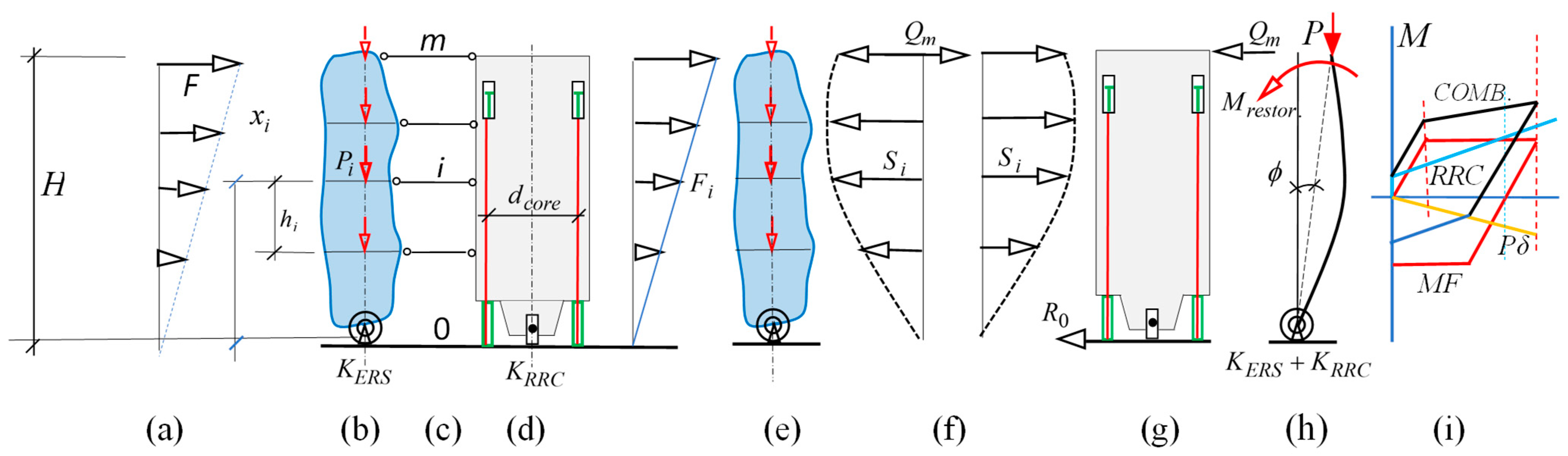
  • The high rigidity of the HRRC forces the entire structure to respond as a Single Degree of Freedom (SDOF) system.
  • The lateral load distribution follows the same profile as the uniform drift of the prototype.
  • The proposed combination can prevent physical collapse and provide self-centering.
  • The use of more than one ductile ERS with different Yield Drift Ratios (YDR) increases the global ductility of the system.
The basic ingredients of the construction economy are time, information, energy, and resources. Time refers to the duration of planning, construction, and service life. Information means knowledge and experience. Energy is the effort needed to materialize the project and conduct PERR as planned. Resources imply the availability of materials, means, and methods of construction. These ingredients, together with relevant economic factors, are grouped together to form a basis for the development of the proposed archetype. The proposed solutions are exactly within the bounds of the theoretical assumptions and are well-suited for preliminary design and teaching purposes. Four groups of economic factors influence the integrity and efficiency of the proposed schemes.

1.1. Constructional Issues

  • Construction technologies: the adoption of pre-manufactured column–tree frames [23,24], with identical members equipped with REDDs.
  • Industrialization: the mass production of identical beams, braces, connections, splices, and REDD parts.
  • Avoiding counterproductive details and introducing purpose-specific arrangements [25].
  • Column length and section selection for the minimum number of splices.
  • The utilization of locally available means and methods of construction.
  • The practicality of disassembly, reassembly, and realignment for PERR.

1.2. Structural Issues

7.
Beam sizing for maximum lateral resistance under combined seismic and gravity forces.
8.
The elimination/reduction of P-delta and residual effects, and similar issues.
9.
The provision of systems that prevent the activation of failure mechanisms during earthquakes [24,26,27,28,29].
10.
Drift control and the imposition of uniform drift along the height of the structure [16].
11.
The elimination/reduction of higher modes of vibration.
12.
The limitation of damage to replaceable energy-dissipating items [30].
13.
The imposition of SDOF responses for all loading combinations.
14.
The estimation of YDR for beams and MFs of uniform strength [31].
15.
The determination of the strength–stiffness YDR relationship for MFs equipped with REDDs.

1.3. Environmental Issues

16.
Carbon footprint and waste reduction, saving time and effort.
17.
Using recycled and recyclable materials as much as possible [32].
18.
The development of maintenance and health-monitoring strategies as part of the structural design strategy [33].

1.4. Repairs and Recentering Issues

19.
The provision of auxiliary elements and systems to enhance structural integrity and prevent collapse during PERR operations [34,35].
20.
The provision of built-in force-generating sources for realignment and static stability during stiffness reduction operations.
21.
The provision of replaceable optional FS devices to prevent premature failure during PERR.
22.
The provision of alternative sources of energy in case of power outages.
Therefore, the development of Triple Steel Structures is the main contribution of the present study, and its features are summarized in Section 1.1, Section 1.2, Section 1.3 and Section 1.4.

2. Theoretical Background and Development

Earthquake-resisting MFs and similar structures are often subject to combinations of P-delta and gravity forces that tend to reduce the lateral resisting capacities of the beams of the systems. Although the development of axial forces in framed structures is unavoidable, the detrimental aspects of P-delta moments and gravity forces can be reduced, or even eliminated, by strategic thinking and thoughtful design. In addition, REDDs tend to modify the strength–stiffness relationships in ERSs. The purpose of this section is twofold. First, to determine the magnitude of the gravity forces below which the full lateral capacity of MF and EBF beams with REDDs may be realized, and second, to understand changes in ultimate stress–strain relationships due to REDD applications.

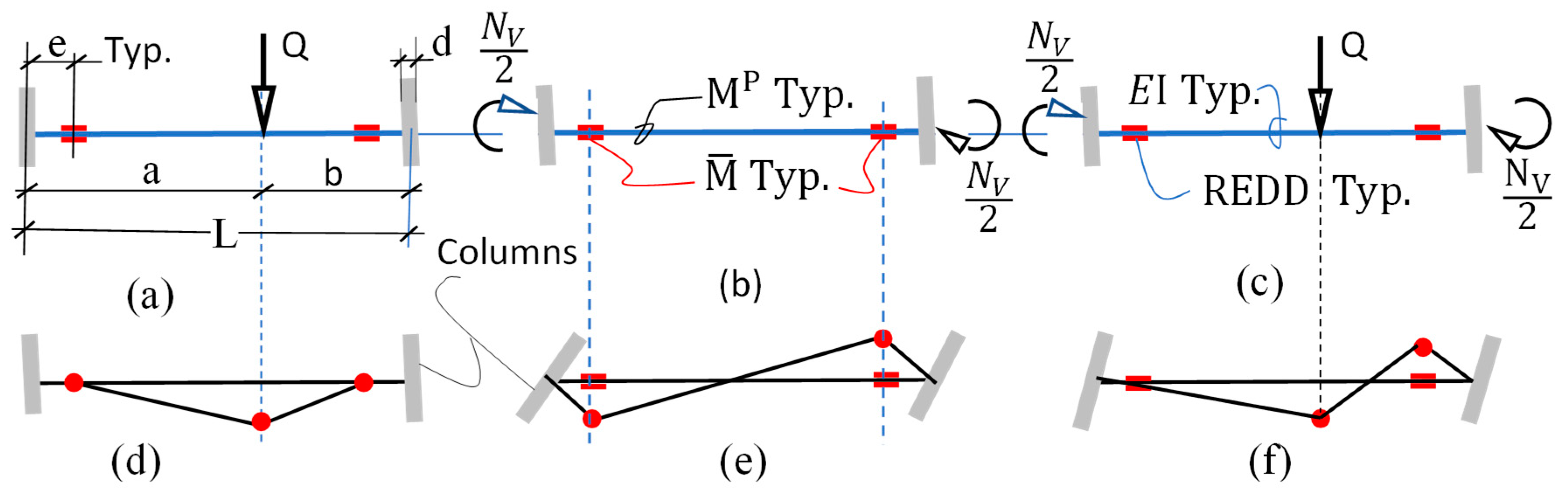
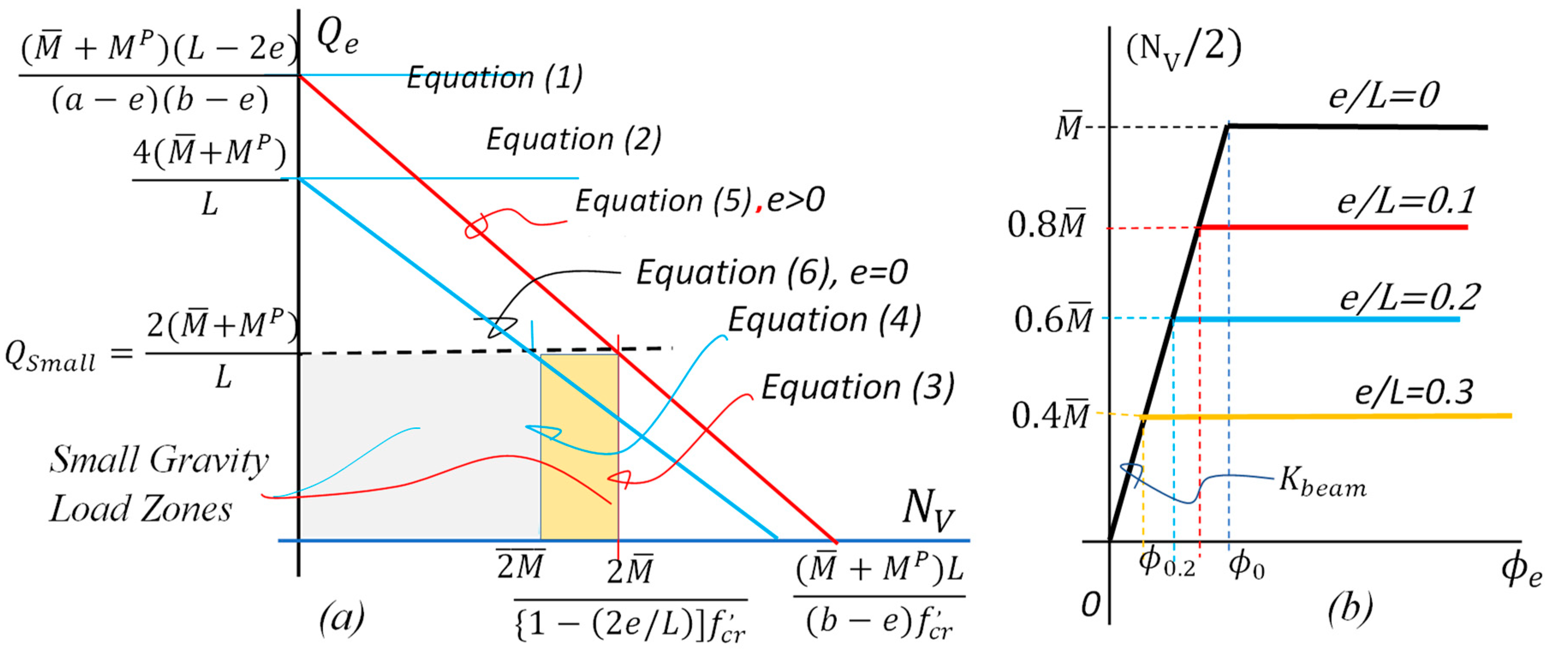
2.1. The Small Gravity Load Concept

Consider the ultimate carrying capacities of the REDD-equipped beams of Figure 1 under pure gravity (Figure 1a), lateral (Figure 1b), and combined loading (Figure 1c) conditions, respectively. The splice material is assumed to be the same as that of the beams. Although the capacity of the system is reduced, its ability for reuse justifies the economics of the arrangement. The corresponding failure mechanisms are illustrated in Figure 1d–f, respectively. Each failure pattern is studied in its most general sense, as well as a standard solution with and without REDDs. Using the principle of virtual work [36,37], the plastic carrying capacities of the three plausible failure mechanisms (Figure 2) were computed as follows:
Case I—Single gravity load Q e (Q in terms of e), N V = 0 (Figure 1a,d):
Q e = ( M ¯ + M P ) ( L 2 e ) ( a e ) ( b e ) ,
Here, M ¯ and M P are defined as the plastic moment capacities of the REDD and parent beam, respectively. N V is the sum of the lateral end moments acting on the beam. For the classic case of a = b = L/2, e = d = 0, Equation (1) gives:
Q e = 0 = 4 L ( M ¯ + M P ) for M ¯ < M P and Q e = 0 = 8 M P L for M ¯ = M P ,
Case II—Lateral end moments, N V /2. ( L / 2 ) > e > 0 (Figure 1b,e):
N V = 2 M ¯ [ 1 2 e / L ] f c r ,
Here, f c r is the critical load quotient due to the global P-delta effect and is further discussed in the forthcoming sections. It is instructive to note at this stage that Equation (3) satisfies all conditions of the “Uniqueness theorem” [38] and, as such, constitutes a minimum weight or economic solution [39]. For the basic case of a = b = L/2, e = d = 0, Equation (3) gives.
N V , e = 0 = 2 M ¯ / f c r for M ¯ < M P and N V , e = 0 = 2 M P / f c r for M ¯ = M P ,
Case III—Lateral and gravity forces combined (Figure 1c,f):
Q e a + N V = ( M ¯ + M P ) L ( b e ) f c r ,
For the case of a = b = L/2, e = d = 0, and M ¯ < M P , Equation (5) gives:
Q e = 0 + 2 N V L f c r = 4 ( M ¯ + M P ) L f c r for M ¯ < M P and Q e = 0 + 2 N V L f c r = 8 M P L f c r for M ¯ = M P ,
Substituting N V , e = 0 from Equation (4) into Equation (6) gives Q e = 0 , min = 4 M P L .

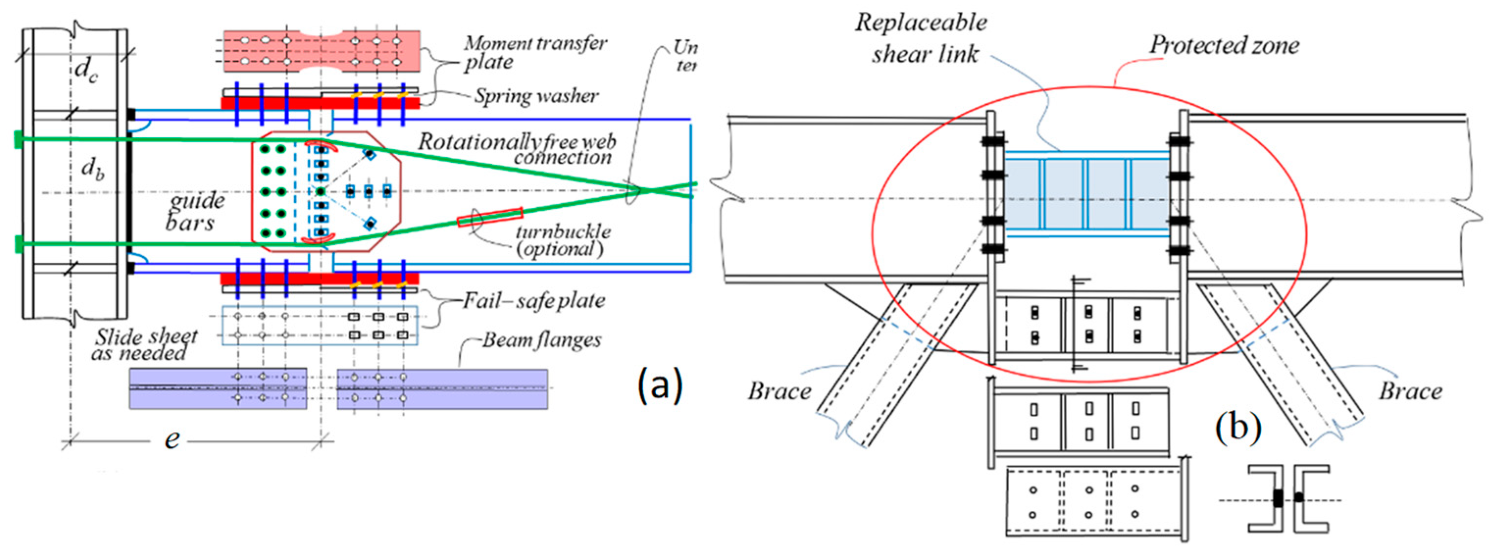
2.2. Strength–Stiffness Relationship of REDD-Equipped Beams

The limit state behavior of simple beams equipped with REDDs differs from that of their unequipped counterparts [29]. Improper use of these relationships may entail the overestimation of lateral capacities and underestimation of drift ratios. The disorderly estimation of sequential failures can result in the overaccumulation of residual effects, and even premature failure of the elements. It is shown that YDR is an important characteristic value for any ductile structure or element under ultimate loading conditions. Consider the parametric relationships among yield rotation ϕ Y , M ¯ , M P and distance e for beam 1(b), ϕ y = [ ( M ¯ L ) / 6 E i ( 1 2 e / L ) ] , in the range 0.5 > (e/L) > 0. Since, to all practical intents and purposes, ( N V / 2 ) M P , the YDR for low-damage beams can be simplified as ϕ Y = ( M P L ) / 6 E I = 0.066 ( M P L / ϕ d b e a m ) % , for Gr. 50 Steel. Graphical solutions 2(b) reveal that contrary to unequipped straight beams: (1) Stiffness is independent of strength. (2) YDR is independent of stiffness but depends on strength. (3) While strength depends on the location of the REDD, stiffness is independent of the strength and location of the splice plates. (4) Since the failure moment and location are controllable, the system is repairable, and therefore, sustainable. (5) The sequence of failures of such beams in parallel connection would be the same as the ascending order of the magnitudes of the corresponding YDRs [40].

3. Moment Frame of Uniform Strength

Comparing the solutions of the three failure mechanisms of Figure 2a reveals that 0 Q Small 2 ( M ¯ + M P ) / L has no effect on the lateral capacity of the system. Furthermore, comparing Q Small with Q Limit = 8 M P / L shows that, in general, Q Small Q Limit / 2 . For instance, the magnitude of a uniformly distributed load may be considered small if it is less than half of its plastic collapse value acting alone on the same beam. Therefore, it may be concluded that small gravity loads have little to no effect on the drift and ultimate lateral capacity of MFs. It is remarkable that N V depends on (e/L) and that the Q Small line intersects Equations (5) and (6) at the same height, i.e., Q Small / L is independent of the location of the REDDs. It is also noteworthy that because of the replaceable RPS joints, all columns and beam middle segments remain elastic throughout the loading history of the structure. Obviously, if all beams of the MF fall into this category, then the MF would become a structure of the minimum weight, as expected. The idea that the size of any REDD-equipped beam of any earthquake-resisting MF, under combined gravity and lateral forces, can be adjusted to attain its full lateral capacity has led to the development of earthquake-resisting MFs of uniform strength (MFUS), where every beam of the system, such as those shown in Figure 3a and Figure 4b, can be adjusted to develop the same M P or M ¯ or both. This, in turn, suggests the possibility of mass production of identical, minimum-weight beams and connections. Henceforth, an MFUS of uniform construction can be construed as a structure of minimum cost, provided certain physical and theoretical conditions are met. However, if the subject MF was conventional, its lateral capacity would be given by:
M o + M P = 2 i = 0 m j = 1 n M i j P     e = 0 ,
If the same MF was equipped with REDDs, Equation (7) would yield:
M o + M P = 2 i = 0 m j = 1 n M ¯ i j     e = 0 ,
Now, if the self-weight of steel beams can be estimated as W = α M P L , where α is a constant, then the difference in the total weights of the beams of the two systems may be assessed as W = α M P ( 2 e / L ) L . For e = 2′ 6″ (46 mm) and L = 25′ 0″ (762 mm), the difference would be in the order of 12%, where M o , M P ,   a n d   M ¯ i j stand for the external overturning moment, global P-delta moment, and REDD plastic moment of resistance, respectively. Obviously, if the beams and REDDs of different bays of the MF could be selected in such a way as to develop their full lateral capacities, then the system would be regarded as an “MF of uniform strength”, where lateral capacities N V , i , per Equation (3), may be expressed as N V , i = N V for i = 1, 2, … m−1 levels, (all floor) and N V , i = N V / 2 for i = 0 and m levels (roof and grade). The total lateral capacity of the MF can now be computed as:
( M M F + M P , M F ) = n N V + m 1 n N V = n m N V
Equal end moments, e.g., Figure 1b,e, give rise to equal rotations at both ends and help form points of inflection at midspan. If, for any reason, theoretical or physical, every beam of an MF is forced to undergo identical end rotations, then the MF would develop a uniform drift profile of the same slope along its height. This configuration is sometimes referred to as an “MF of uniform response”.

3.1. MF Design Strategies

The efficiency and integrity of lateral resisting MFs, as in any structure, depends largely on interpretations of prevailing code requirements, design philosophy, and the judgment of the designers. The relevant case in question is the required RBS code for special MFs. Here, the intention is to save the columns at the expense of damaged beams with plastic hinges at RBS locations, regardless of the possibility of the formation of plastic hinges at column supports, resulting in an incapacitated MF. The formation of plastic hinges at the column feet can be averted by introducing RBS- or RPS-equipped grade beams along the supports. Damage to the beams can also be avoided by replacing the conventional RBS splices with replaceable, low-damage RPS/REDD connectors. Similar design strategies may be adopted to facilitate the preliminary design of MFUS construction as part of sustainable triple systems, e.g.,
  • Select ( N V / 2 ) = M P , so that M f a c e , c o l = ( 1 d / L ) M P automatically satisfies the code requirement 0.8 M P < M f a c e , c o l M P .
  • Select the ratio ( M ¯ / M P ) as a constant and work out e = 1 M ¯ M P L / 2 for each beam. This option is rather efficient for small variations in L.
  • Keep M ¯  and e constant, and work out M P = M ¯ / 1 2 e L for each bay.
  • Keep M P and e constant, and work out M ¯ = 1 2 e L M P .
  • For small variations in story heights, select the end column properties, half of those for inner bays.
  • For small variations in story heights, select the roof- and grade-level beam properties, half of those for other levels.

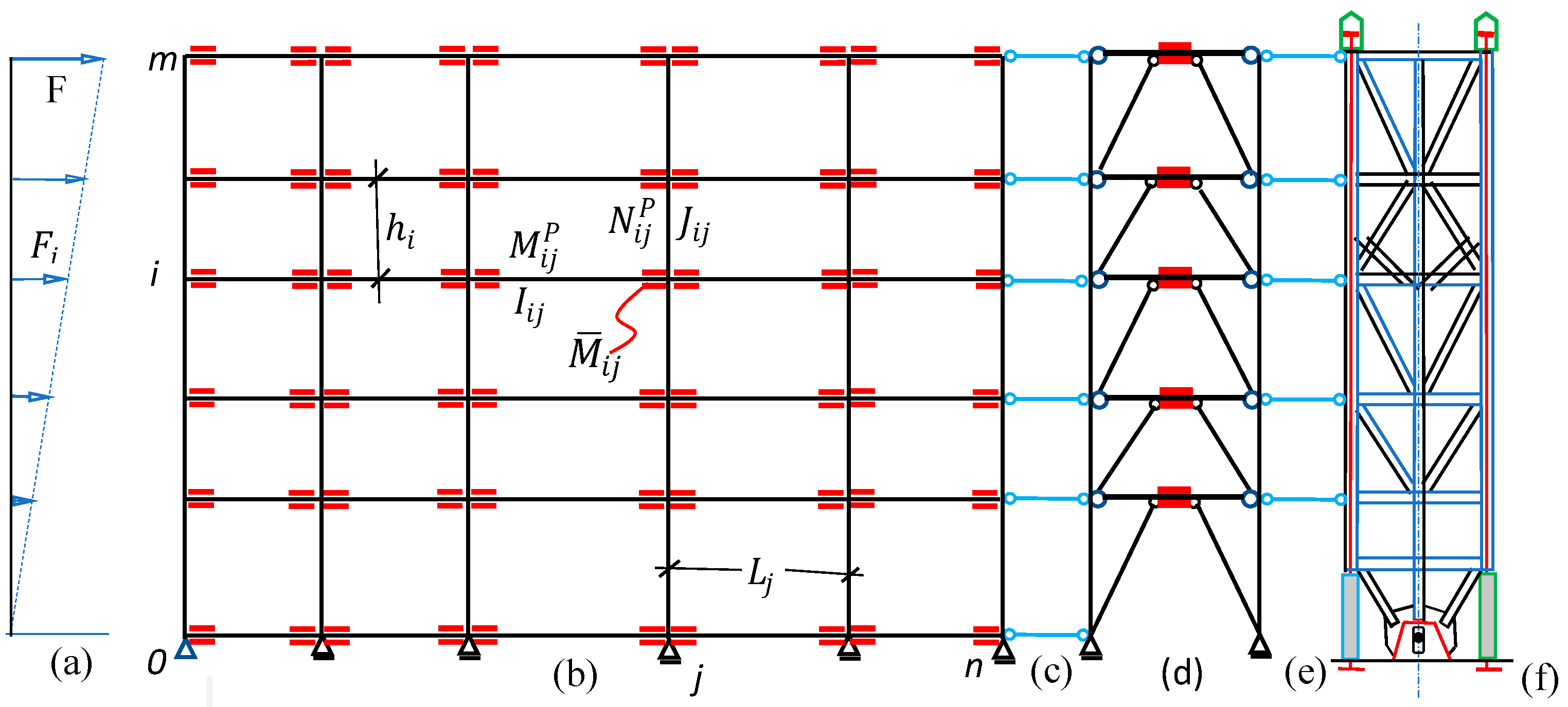
4. Development of a Generic Sustainable Triple System

A free body diagram of an m-story, a triple system composed of an articulated gravity structure, a ductile ERS (such as an MF), and an HRRC under lateral (F) and gravity (P) forces is shown in Figure 5. The parent or gravity structure lacks lateral stiffness, and as such, is not included in Figure 5. The imaginary, pin-ended, axially rigid link beams emulate a parallel connection between the three systems. Assume that shear and axial deformations of the MF are negligible compared with the bending effects. Although the largest portion of the P-delta moment is due to the gravity system, its line of action is displayed along the vertical axis of the MF for convenience. The HRCC, being extremely rigid, acts as an SDOF system and tends to absorb the entire lateral load. Under such circumstances, it seems rational to assume that the drift ratio equals ϕ = ( M o + M P ) / K System and that if there are s number of ERSs within the group, then:
ϕ = ( M o + M P ) r = 1 s K E R S , r ,
It would also be rational, in this case, to divide the total external moment in proportion to the stiffnesses of the two systems, i.e.,
M o + M P M F = ( M o + M P ) K M F K M F + K R R C and M o + M P R R C F = ( M o + M P ) K M R R C K M F + K R R C ,
And in the general case defined above:
M o + M P M I S C = ( M o + M P ) M I S C r = 1 s K E R S , r ,
As indicated in Figure 5g, the upper reaction Q holds the core in place and subjects the MF to a pure shear Q along its height. The formation of points of inflection at the midspans of all beams and columns of the MF is consistent with the uniform drift profile ϕ. This implies that each half of each beam and column will develop end moments equal to M i j = 6 E I i j θ b e a m / L j and N i j = 6 E J i j θ c o l u m n / h i , respectively. Since the response of the combined structure is a function of the same single variable ϕ, the external moment M o + M P M F = i = 1 m ( F i + P i ϕ ) x i , where P i = l = 1 n p i , can be related to uniform end rotations θ b e a m and θ c o l u m n , i.e., ϕ = θ b e a m + θ c o l u m n . Defining k i j = I i j / L j and k ¯ i j = J i j / h j i gives:
ϕ = M o + M P M F 12 E 1 i = 0 m j = 1 n δ i j k k i j + 1 i = 1 m j 0 n k ¯ i j = M M F K M F f c r , B F ,
A result previously derived from long-hand analysis [41], f c r , B F = ( 1 P c r , M F / K M F H ) is the critical load quotient related to the MF. Following the same rationale, similar expressions can be derived for all other ERSs of the prototype, i.e., ϕ = M B F / K B F f c r , B F , ϕ = M H R R C / K H R R C f c r , H R R C , etc. Here, Kronecker’s delta, δ i j k , is intended to help track the post-earthquake unstiffening of the MF as needed. It refers to the effective or diminished stiffness of beam ij after an earthquake. Conventionally δ i j k = 1 if K S   >   0 , and δ i j k = 0 if K S   =   0 . Figure 5i displays a generic individual and combined response diagram of the system.

4.1. Case Study 1

Given the configuration of Figure 3b as part of a seismically sustainable triple system involving REDDs and an HRRC, we propose an MFUS of uniform construction, and estimate the corresponding YDR. Assume that ( M ¯ / M P ) = 0.85 ,   Q i j = 0 , M P = 0 , h i = h = 0.6   L , and J (column) = 1.10 × I (beam).
Solution: The proposed design strategies of Section 3.1 give:
Strategy 6: M i = 1,2 , 3,4 , j P = M P , M 0 , j P = M 5 , j P = M P / 2 .
Strategy 6: I i = 0 , j = 1 , 2 , 3 = I i = 5 , j = 1 , 2 , 3 = I 2 . I i = 1 , 2 , 3 , 4 , j = 1 , 2 , 3 = I .
Strategy 5: J i = 0 , 1 , 2 , 3 J i = 1 , 2 , 3 , 4 , 5 , j = 0 = J i = 1 , 2 , 3 , 4 , 5 , j = 4 = J 2 J i = 1 , 2 , 3 , 4 , j = 1 , 2 , 3 = J .
Strategy 2: e = 0.075 L, 0.075 × 1.5 L, 0.075 × 1.25 L, and 0.075 × 1.25 L for bays 1, 2, 3, and 4, respectively. Obviously, the lateral capacity of the subject MF can be computed as follows: 2 M ¯ × 4 × 5 = 40 × 0.85 M P = 34 M P = M o , as compared with 40 M P =   M o  for a regular, unsustainable counterpart. Equation (14) gives:
ϕ Y = 34 M P 12 E L 5 1 1 + 1 1.5 + 2 1.25 I + ( h = 0.6 L ) 5 × 4 ( J = 1.1 I ) = 0.11 L d b e a m %

4.2. Case Study 2

Strategy 3 is to redesign the MF of Section 3.1 and envisage a bay-by-bay plastic failure sequence before decapacitation. Let e = 0.1 L and ϕ y   bay   1 < ϕ y   bay   3 , 4 < ϕ y   bay   2 .
Solution: Strategy 3 gives: M i = 0 , j = 1 P = M i = 5 , j = 1 P = 0.8 M P / 2 , M i = 0 , j = 2 P = M i = 5 , j = 2 P = 0.87 M P / 2 , M i = 0 , j = 3 , 4 P = M i = 5 , j = 3 , 4 P = 0.84 M P / 2 . Similarly, M i = 1 , 2 , 3 , 4 , j = 1 P = 0.8 M P , M i = 1 , 2 , 3 , 4 , j = 2 P = 0.87 M P , M i = 1 , 2 , 3 , 4 , j = 3 , 4 P = 0.84 M P .
The lateral capacity of this case can be computed as follows:
5 × 2 M B a y , 1 P + M B a y , 2 P + M B a y , 3 P + M B a y , 4 P = 10 0.80 + 0.87 + 0.84 + 0.84 M P = 33.5 M P = M o . The capacity equation may be generalized as follows:
2 m   j = 1 n δ j P M B a y   j P = M o
Here, Kronecker’s delta δ j P = 1 if ( 2 m M B a y   j P ) > 0, and δ j P = 0 if ( 2 m M B a y   j P ) = 0. The sequence of failures of the bays is the same as the ascending order of the YDRs.

5. EBF of Uniform Strength as Part of Triple ERS

The lateral analysis of EBFs, as part of a triple ERS, e.g., Figure 4d and Figure 6a, is cumbersome using conventional methods of study. However, the HRRC forces the EBF to respond as an SDOF structure and tilt as a straight-line drift profile, ϕ i = ϕ . This, in turn, helps simplify the analysis of the system. The columns and braces are assumed to neither yield, buckle, nor carry bending moments. The continuous beams are high-grade wide flange sections equipped with or without special REDDs [42,43]. Although almost all commercially available software can be used to analyze EBFs of uniform drift, the following formulations have also been provided to assist with preliminary design purposes. The parametric analysis is conducted in two interrelated steps.
Step 1: As can be seen from Figure 6b, M E B F , i P = V e / 2 . Here, M E B F P  refers to the plastic moment of resistance of the beam or the REDD (whichever is present). From static equilibrium (Figure 6a), 2 m V L = ( Q H + M P ) , and in general:
V i = V = [ ( Q H = M o ) + M P ] E B F 2 m L and M E B F , i P = ( Q H + M P ) e 4 m L ,
And for the lateral capacity of the EBF:
Q = 4 m L M E B F , i P e H M P H
Assume that M P = 0 for simplicity’s sake. The equilibrium of subframe m (Figure 6b) reveals that:
V B r c = V L ( L ε / 2 ) = Q H 2 m ( L ε / 2 ) ,   R m = Q H ε 4 m ( L ε / 2 ) L ,   and   T C o l , m = R m = Q H ε 4 m ( L ε / 2 ) L ,
The axial forces of the braces, columns, and beams can be estimated as follows:
T B r c , m = V B r c , m L ¯ m h m = Q H L ¯ m 2 m ( L ε / 2 ) h m ,   S m = Q 2   and   T C o l , m = R m = Q H ε 2 m ( L ε / 2 ) L ,
where L ¯ is the length of the brace. The compatible deformations of the roof-level subframe can be estimated as follows:
δ S , m = S m ( L ε / 2 ) A b e a m E ,   δ b r c , m = T b r c , m L ¯ m A b r c , m E ,   δ c o l , m = T c o l , m h m A c o l , m E ,   M x E I = R m E I x V B r c < x L ε / 2 >
The virtual forces generated in the elements of subframe m due to a unit force acting in the same sense as Q can be written down as:
f S , m = 1 ,   f b r c , m = H L ¯ m 2 m ( L ϵ / 2 ) h m ,   f c o l , m = H ε 2 m ( L ϵ / 2 ) L ,   m x = r m x v m < x L ε / 2 >
The virtual work equation yields the uppermost subframe lateral displacement as follows:
1 × m = f S , m δ S , m + f b r c , m δ b r c , m + f c o l , m δ c o l , m + 0 L M x E I m x d x
m = S m ( L ε / 2 ) A b e a m E + H L ¯ m 2 m ( L ϵ / 2 ) h m T b r c , m L ¯ m A b r c , m E + H ε 2 m ( L ϵ / 2 ) L T c o l , m h m A c o l , m E Q ε 2 H 2 24 I b e a m , m E m 2 L ,
The step 1 roof-level displacement due to beam bending can be computed as:
δ B e a m , m = Q H 2 ε 2 24 m 2 E L i = 1 m 1 I i    or    δ B e a m , m = Q H 2 ε 2 24 m E I L    for   I i = I
The contribution of deformations of elements of subframe i can be expressed as:
Δ 1 , i = δ B e a m , i + δ B r c , i + δ A x i a l B e a m , i = Q H 2 ε 2 24 m 2 E I i L + 2 Q H 2 L ¯ i 3 m 2 ( L ε ) 2 A B r c , i E h i 2 + ( L ε ) Q H 2 2 m 2 A B e a m , i E h i 2
The nature of Equation (25) is remarkable in that it not only provides a measure of the contribution of the strength and stiffness of any subframe to the global integrity of the EBF, but also suggests how the stiffness of the structure can be reduced for PERR purposes. The total roof-level lateral displacements due to beam and brace stresses can now be computed as:
δ B r c , m = 2 Q H 2 m 2 ( L ε ) 2 E i = 1 m L ¯ i 3 A B r c , i h i 2 and δ A x i a l B e a m , m = ( L ε ) Q H 2 2 m 2 E i = 1 m 1 A B e a m , i h i 2 ,
Consequently, the step 1 total lateral roof-level displacement and global drift can be expressed as:
Δ 1 , m = i = m m δ B e n d , i , m + δ B r c , i , m + δ A x i a l B e a m , i , m , φ 1 = Δ 1 , m H and Δ 1 , i = φ r = 1 i h r ,
Note that at this step, the vertical displacement Δ ¯ 1 , i = 0 is still zero for all nodes. In step 2, the column axial force and the corresponding axial deformations, δ ¯ C o l , i , can be calculated as:
T C o l , i = T C o l , i + 1 + V B R C , i + 1 R i   i = m ,   i + 1 ,   i   2 ,   1   and   δ ¯ C o l , i = r = 1 i T C o l , r h r A C o l , r E
Step 2: Next, the lateral displacements of the EBF due to the axial strains of the chords are studied. Figure 6d shows that each story tends to rotate θ i = 2 δ ¯ C o l , i / L , in the same sense as the overturning moment. Since the structure rotates as a rigid body due to axial strains, the corresponding uniform drift and nodal lateral displacements can be estimated as Δ 1 , i  and Δ 2 , i = φ 2 r = 1 i h r , respectively. Consequently Δ i = Δ 1 , i + Δ 2 , i and φ = φ 1 + φ 2 . The axial displacement L ¯ i of any diagonal brace, such as that shown in Figure 6f, can be related to its end displacement as ( l ¯ ± Δ B R C , i ) 2 + ( h ± Δ ¯ B r c , i ) 2 = ( L ¯ i ± L ¯ i ) 2 , where l ¯ = ( L ε ) / 2 , and the plus and minus signs refer to the tensile and compressive forces of the brace, respectively. After omitting the small quantities, e.g., Δ 2 , the change in length of the brace can be expressed as:
L ¯ i = l ¯ L ¯ i Δ B R C , i + h i L ¯ i Δ ¯ B r c , i = Δ B R C , i cos θ i + Δ ¯ B r c , i sin θ i
Once the global drift ratio φ and overturning moment M o + M P E B F are known, the stiffness of the EBF can be worked out as K E B F = M o + M P E B F / ϕ .

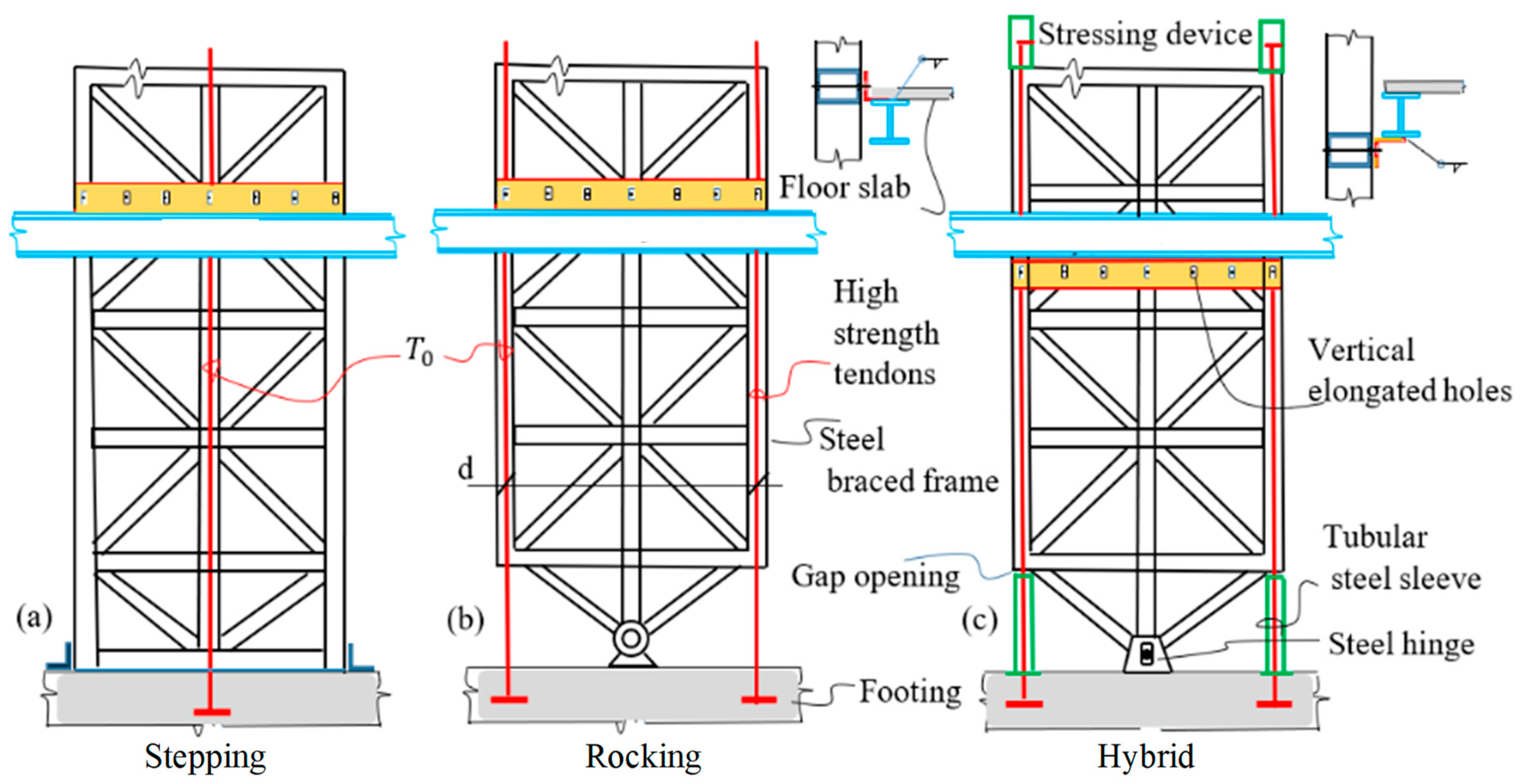
6. The Hybrid Rigid Rocking Core

In conventional combined systems, the articulated gravity structure, the MF, and the EBF lack the ability to realign the structure back to its original position after strong ground shaking. Fixed-base shear walls are prone to damage beyond repair. Residual deformations restrict the controllability of standard ERSs after earthquakes. RRCs, the predecessors of HRRCs, with many favorable attributes [44], are remarkable and have helped achieve reliable results [12,45,46]. Both the stepping and the rocking systems (Figure 7a,b, respectively) have certain merits and drawbacks. The HRRC (Figure 7c) is designed to overcome the negative aspects of some of these issues. Here, the authors propose a novel core (Figure 7c) that displays the merits and avoids the drawbacks of both systems. The RRC, sometimes referred to as the “building spine” [47], is simply a very stiff upright trussed girder, loosely supported on short steel sleeves at its lower edges and restrained against lateral movement by a ground-level central hinge that allows it to rock sideways with small gaps opening and closing on alternate sides. Unlike stepping and regular rocking walls, the HRRC does not derive its strength and stability from massive self-loads or added weights but from the tensile strength of high-grade tendons and elastic compression of the sleeves. The high-strength tendons and sleeves are designed to remain elastic even after target displacement, ϕ M a x . , is exceeded. The HRRC is considered rigid if its story drift ratio does not exceed 0.25% (radians). The stressing jacks are meant to adjust the tendon forces as needed. If needed, the core may be initially stressed while resting on top of the sleeves. The restoring characteristics of HRRCs are defined by their rigidity, ultimate strength, and base-level rotational stiffness. The core drift ratio can be expressed in terms of core moment M C and rotational stiffness K R R C as:
ϕ = H A t E t + h A s E s ( M o + M P ) R R C d 2 = ( M o + M P ) R R C K R R C
The YDR for the HRCC can be estimated as ϕ Y = 2 T Y H d A t E t 1.86 H d H R R C % . Here, symbols A and E define the section area and young’s modulus, respectively. The subscripts t and s stand for tendon and sleeve, respectively. H and h refer to the effective tendon length and sleeve height, respectively. K R R C = 0 if neither the high-strength tendons nor the steel sleeves are used as supplementary elements. To ensure that the HRRC remains functional, even after sleeve crushing, the tensile strength of the tendons should be selected such that T Y i e l d > >   A t E t .

Case Study 4

Figure 7 provides preliminary design data for the stepping, rocking, and hybrid rigid rocking cores. Let T 0 denote the initial tension for all three cases.
Discussion: A complete summary of this study is presented in Table 1, where the letters T and C stand for cable tension and sleeve compression, respectively. The subscripts l and r refer to the left- and right-hand sides, respectively, and show that the advantage of the hybrid system over the stepping core is that the moment-resisting arm of the former is twice that of the latter. Activation of the sleeves eliminates the loss of pretension in the leeward tendons. The sleeves also provide static stability for the HRRC and act as FS devices against tendon snapping or relaxation. The sleeves and tendons are compression- and tension-only members, respectively.

7. The Analysis and Design of the Archetype

The analysis of the proposed archetype is conducted in two separate but related Sections. In Section 7.1, the triple ERS that is supposed to support and protect the gravity framing is designed to withstand prescribed earthquakes without falling apart, albeit sustaining major but repairable damage. The next section outlines the steps needed to realign and repair the system as economically and effortlessly as possible [48].

7.1. Seismic Resistance

Here, for the sake of expediency, the proposed archetype is construed as being composed of five theoretically different structures: 1—the parent or gravity framing with zero lateral stiffness, K E G R A V = 0 , and ϕ Y = ; 2—the phantom P-delta system with negative stiffness, K P d e l t a , and ( ϕ Y ) ; 3—the MF with K M F and ϕ Y 1.0 % ; 4—the EBF with K E B F and ϕ Y 0.5 % ; and 5—the HRRC with K R R C and ϕ Y 3.5 % . Since ϕ Y , P D d e l t a < ϕ Y , E B F 0.5 % < ϕ Y , M F 1 % < ϕ Y . R R C 3.5 % . < ϕ Y , G r a v = , the sequential failure theorem would indicate that (Figure 4):
  • First, the EBF will fail by forming a stable failure mechanism while supporting the P-delta system and leaning on the MF.
  • Next, the MF will undergo a plastic failure mechanism while leaning on the HRRC.
  • The HRCC will remain intact and elastic, even beyond ϕ M a x , while supporting the damaged RRCs and the undamaged gravity systems.

7.2. Post-Earthquake Realignment and Repair
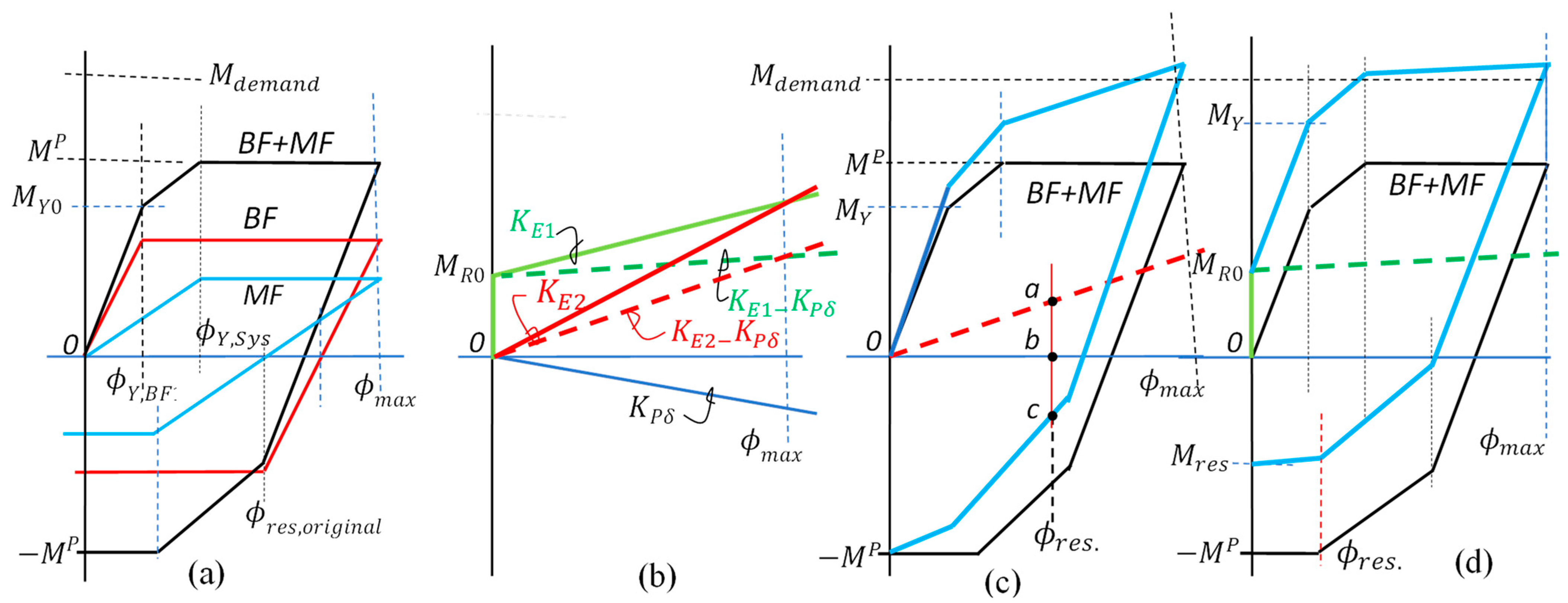
Depending on the design strategy, the HRRC may or may not be able to fully recenter the archetype by itself [7]. To understand the mechanics of recentering, consider the responses of a group of ductile ERSs and options for restoring systems in Figure 8a,b, respectively. The dashed and solid black lines, Figure 8c,d, depict the responses of the combined ductile ERSs and all ERSs together, respectively. Here, the assumption is that the HRRC is the only ERS that remains elastic beyond ϕ m a x . (Figure 8b), with no other restoring force to help recenter the combined system. Comparing the effectiveness of the three options for realignment without GSR + RFA, it may be observed that demand is satisfied in all three cases. The subtleties are remarkable and need to be appreciated for proper GSR + RFA.
  • Option K E 1 (Figure 8c): Forced recentering is achieved with a reduced residual moment (0a − M R 0 ), which is not as satisfactory as M R 0 0 a , and requires storing a large preload within the structure. Recentering is materialized because the ordinance of the restoring effect is larger than that of the combined system at ϕ r e s . , i.e., the restoring force is sufficient to overcome the plastic resistance of the system at that point.
  • Option K E 2 (Figure 8d): Full recentering is not achieved. The restoring ordinance is less than that of the plastic resistance at ϕ r e s . . The total residual moment 0a is not satisfactory either, since M R 0 = 0 .
  • Option K E 3 (Figure 8e): Neither forced recentering nor residual moment reduction can be achieved due to a lack of stored energies at the early stages of loading. This case is ideally suited for GSR + RFA treatment. Line ( 0 ϕ r e s . ) suggests a possible load path for GSR. It also implies that no premature slackening of the tendons can be allowed for cases K E 1 and K E 2 , unless GSR + RFA is also envisaged.

7.3. GSR and the Single Vector Concept

Following the arguments presented in the preceding section, the analysis and production of the corresponding diagrams can be simplified substantially by treating the response of the original combination as that of a single, equivalent structure (Figure 9a) and that of the P-delta and restoring systems (Figure 9b) as another. Figure 9a displays the individual and combined responses (initial supply) of the MF and BF of a triple system, where ϕ Y , S y s and ( M P ) refer to system yield drift and residual moments in the absence of P-delta and restoring forces. Initially, the supply is less than the prescribed demand, M P <   M d e m a n d , and the likely initial residual deformation ϕ r e s , o r i g i n a l > 0 . This can be rectified by adding a suitable RRC/restoring mechanism to the original system. Figure 9b illustrates the responses of two types of restoring system, the preloaded K E 1 and the non-preloaded  K E 2 , and their combinations, ( K E 1 K P δ ) and ( K E 2 K P δ ) , with the P-delta effect (dashed lines). Note that all responses in Figure 9b extend beyond ϕ M a x . , i . e . , they remain effective even after everything else has been incapacitated. The novelty here is that the quantity ( K E K P δ ) can be used as a single vector to reduce design effort as a deciding factor when combined with the supply system of the original combination. Figure 9c,d show the effects of combining ( K E 1 K P δ ) and ( K E 2 K P δ ) with the original system of Figure 9a. It may be observed, in Figure 9c, that the restoring force marked by point a is less than the force needed to recenter the system, point b. In geometric terms, ab < bc and ϕ r e s . = 0a, implying that system K E 2 is ineffective and that use should be made of either the GSR or system K E 1 , or a combination of G S R + K E 1 .  Figure 9d shows that since M R 0 0 , both the residual deformations and moments can be decreased, or even eliminated, if M R 0 M r e s . .
The findings of this section are utilized to develop the following formulae for quick referencing, investigation, and preliminary design purposes. It may be observed from the ( M ϕ ) plots that, in general,
M d e m a n d = M P + K E K P δ ϕ m a x
and that for ideal restoration to take place,
K E K P δ ϕ max + M P = 2 [ M R 0 + ( K E K P δ ) ϕ Y , 1 + M Y 0 ] ,
or
K E K P δ = 2 [ M R 0 + M Y 0 ] M P ( ϕ m a x 2 ϕ Y , 1 )
Test: Let K P δ = M R 0 = 0 ,   M Y 0 = M P  and ϕ Y , 1 = ϕ max / 4 . Equation (33) gives K E = 2 M P ϕ max or M r e s t o r e = 2 M P , a result previously reported by Eatherton et al. (2014) [30]. Equation (33) can be used directly to satisfy the following design conditions.
Demand–supply requirements: M s u p p l y M d e m a n d , ϕ R R C , Y > ϕ m a x and ϕ < ϕ m a x .
Recentering requirements: K E > K P δ , M r e s = 0 and ϕ r e s = 0 .
Residue reduction condition: M r e s = 0 , can be satisfied if M 0 R M P .
Perfect recentering is possible if 2 M Y M s u p p l y , where M Y = [ M R 0 + K E K P δ ϕ Y , 1 + M Y 0 ] , and M Y 0 = ϕ Y , 1 i = 1 r K i .

8. Conclusions

It has been shown that combining the principles of “performance control”, “plastic design”, and the use of low-damage “replaceable energy-dissipating devices”, together with lessons learned from past experiences, can lead to the SSD of triple earthquake-resisting structures. In other words, conventional design can be upgraded to economy-wise SSD without resorting to untenable costs and technologies. The difference between conventional design and SSD is in their approach to expected behavior during and after major earthquakes. Despite its undeniable importance, SSD has not found its proper place in contemporary curricula or codes of practice. The research effort leading to the preparation of this paper was prompted by the notion that efficient SSD can be achieved by addressing the following practical issues:
  • Constructional issues, as presented in Section 1.1.
  • Structural issues, as listed in Section 1.2.
  • Environmental issues, as referred to in Section 1.3.
  • Recentering and repair issues pointed out in Section 1.4.
  • Theoretical and conceptual issues, as discussed within the text.
In the interim, a few newly developed concepts and methodologies that facilitate the development of SSD and its applications to triple systems have also been introduced, namely:
  • The small gravity load concept presented in Section 2.1.
  • The strength–stiffness relationship of REDD-equipped beams, discussed in Section 2.2.
  • MFs of uniform strength as part of triple ERSs, as reported under Section 3.
  • The development of a generic sustainable triple system outlined, in Section 4.
  • The analysis of EBFs of uniform strength as part of a triple ERS, outlined in Section 5.
  • The hybrid rigid rocking core as part of a triple ERS introduced in Section 6.
  • GSR and the single vector concept, as described under Section 7.3.
It is hoped that this and similar documents will help provide a basis for the development of even more efficient SSDs in future generations of guidelines and codes of practice.

Author Contributions

Conceptualization, M.G.; methodology, M.G. and A.S.M.; formal analysis, A.M.; investigation, A.M.; writing—original draft preparation, A.M.; writing—review and editing, M.G.; visualization, A.M.; supervision, A.S.M.; project administration, M.G. All authors have read and agreed to the published version of the manuscript.

Funding

This research received no external funding.

Institutional Review Board Statement

Not applicable.

Informed Consent Statement

Not applicable.

Data Availability Statement

No new data were created.

Conflicts of Interest

The authors declare no conflict of interest.

References

  1. Eurocode-8; Design of Structures for Earthquake Resistance. European Standards: Brussels, Belgium, 1998.
  2. Priestly, M.J.N. Performance-based seismic design. In Proceedings of the 12th World Conference on Earthquake Engineering, Auckland, New Zealand, 30 January–4 February 2000. [Google Scholar]
  3. ASCE/SEI 7-2016; Minimum Design Loads and Associated Criteria for Buildings and Other Structures. ASCE: Reston, VA, USA, 2016.
  4. Krawinkler, H.; Deierlein, G.G. Challenges towards achieving earthquake resilience through Performance-Based Earthquake Engineering. In Performance-Based Seismic Engineering: Vision for an Earthquake Resilient Society; Fischinger, M., Ed.; Springer: Berlin/Heidelberg, Germany, 2014; pp. 3–26. [Google Scholar]
  5. Aukeman, L.J. Evaluation of the ASCE7-05 Design Rule for Relative Strength in a Tall Buckling-Restrained Braced Frame Dual System. Master’s Thesis, California Polytechnic State University, San Luis Obispo, CA, USA, 2011. [Google Scholar]
  6. Grigorian, M.; Sedighi, S.; Targhi, M.A. Sustainable Earthquake-Resistant Mixed Multiple Seismic Systems. J. Struct. Eng. 2023, 149, 3. [Google Scholar] [CrossRef]
  7. Gilmore, A.T. Options for sustainable earthquake-resistant design of concrete and steel buildings. Earthquakes Struct. 2012, 3, 783–804. [Google Scholar] [CrossRef]
  8. MacRae, G.A.; Kimura, Y.; Roeder, C. Effect of Column Stiffness on Braced Frame Seismic Behavior. J. Struct. Eng. 2004, 130, 381–391. [Google Scholar] [CrossRef] [Green Version]
  9. Ma, X.; Borchers, E.; Pena, A. Design and Behavior of Steel Shear Plates with Openings as Energy Dissipating Fuses; Technical Report 173; John, A., Ed.; Blume Earthquake Engineering Center: Stanford, CA, USA, 2011. [Google Scholar]
  10. Hajjar, F.; Sesen, A.; Jampole, E.; Wetherbee, A. A Synopsis of Sustainable Structural Systems with Rocking, Self-Centering, and Articulated Energy-Dissipating Fuses; Department of Civil and Environmental Engineering Reports, Report No. NEU-CEE2013-01; Northeastern University: Boston, MA, USA, 2013. [Google Scholar]
  11. Grigorian, M.; Grigorian, C.E. Performance Control: New Elastic-Plastic Design Procedure for Earthquake Resisting Moment Frames. J. Struct. Eng. 2012, 138, 812–821. [Google Scholar] [CrossRef]
  12. Wiebe, L.; Christopoulos, C. Controlled rocking systems for enhanced seismic resilience: State of the art. In Sustainable Development of Critical Infrastructure; Liu, X., Ang, A.H.-S., Eds.; ASCE: Reston, VA, USA, 2014; pp. 496–503. [Google Scholar]
  13. Pessiki, S. Sustainable Seismic Design. Procedia Eng. 2017, 171, 33–39. [Google Scholar] [CrossRef]
  14. Gebelein, J.; Barnard, M.; Burton, H.; Cochran, M.; Haselton, C.; McLellan, R.; Porter, K. Considerations for a framework of resilient structural design for earthquakes. In Proceedings of the SEAOC Convention, San Diego, CA, USA, 12–15 September 2017. [Google Scholar]
  15. Fang, C.; Wang, W.; Qiu, C.; Hu, S.; MacRae, G.A.; Eatherton, M.R. Eatherton Seismic resilient steel structures: A review of research, practice, challenges and opportunities. J. Constr. Steel Res. 2022, 191, 107172. [Google Scholar] [CrossRef]
  16. Wada, A.; Mori, N. Seismic Design for the Sustainable City: A Report on Japanese Practice. In Structures Congress 2008: Crossing Borders; ASCE: Reston, VA, USA, 2008. [Google Scholar] [CrossRef]
  17. Deierlein, G.G.; Ma, X.; Eatherton, M. Collaborative research on development of innovative steel braced on mitigation of drift frame systems with controlled rocking and replaceable fuses. In Proceedings of the 6th International Conference on Urban Earthquake Engineering, Tokyo, Japan, 3–4 March 2009. [Google Scholar]
  18. ASCE. Sustainability, ASCE/SEI Sustainability Committee; ASCE: Reston, VA, USA, 2014; Available online: http://www.asce.org/sustainability/ (accessed on 6 April 2023).
  19. EC (European Commission). Seismic Performance Assessment Addressing Sustainability and Energy Efficiency; Publications Office of the EU: Brussels, Belgium, 2014. [Google Scholar]
  20. Lu, Y.; Panagiotou, M. Earthquake damage resistant multistory buildings using 7 combination of base isolation and rocking core walls. In Proceedings of the 1st Huixian International Forum on Earthquake Engineering, Harbin, China, 16–19 August 2014. [Google Scholar]
  21. Naeim, F. The Seismic Design Handbook; Kluwer Academic Publishers: Norwell, MA, USA, 2001. [Google Scholar]
  22. Kam, W.Y.; Jury, R. Performance–based seismic assessment: Myths and fallacies. In Proceedings of the NZSEE Conference, Wellington, New Zealand, 10–12 April 2015; pp. 673–687. [Google Scholar]
  23. Astaneh-Asl, A. Seismic Design of Steel Column-Tree Moment-Resisting Frames; Structural Steel Educational Council: Lafayette, CA, USA, 1997. [Google Scholar]
  24. Astaneh, A.; Call, S.M.; McMullin, K.M. Design of single plate shear connections. Eng. J. 1989, 26, 21–32. [Google Scholar] [CrossRef]
  25. Chancellor, N.B.; Eatherton, M.R.; Roke, D.A.; Akbaş, T. Self-Centering Seismic Lateral Force Resisting Systems: High Performance Structures for the City of Tomorrow. Buildings 2014, 4, 520–548. [Google Scholar] [CrossRef] [Green Version]
  26. Grigorian, M.; Moghadam, A.S.; Kamizi, M. On repairable earthquake resisting archetypes with a view to resiliency objectives and assisted self-centering. Struct. Des. Tall Spéc. Build. 2019, 28, e1603. [Google Scholar] [CrossRef]
  27. Fahnestock, R.; Sause, J.; Ricles, B.; Simpson, M.; Kurata, T.; Okazaki, Y.; Kawamata, Z.; Tao, J.; Duke, D.; Rivera, B.; et al. US-Japan collaboration for shake table testing of a frame-spine system with force-limiting connections. In Proceedings of the 17th World Conference on Earthquake Engineering, online, Japan, 27 September–2 October 2021. [Google Scholar]
  28. Eatherton, M.R.; Ma, X.; Krawinkler, H.; Deierlein, G.G.; Hajjar, J.F. Quasi-Static Cyclic Behavior of Controlled Rocking Steel Frames. J. Struct. Eng. 2014, 140, 11. [Google Scholar] [CrossRef]
  29. Grigorian, M.; Kamizi, M.; Sedighi, S. A basis for developing sustainable earthquake-resisting structures. In Proceedings of the Institution of Civil Engineers-Structures and Buildings; ICE: London, UK, 2021; Volume 174, pp. 516–533. [Google Scholar] [CrossRef]
  30. Karavasilis, T.; Blakeborough, T.; Williams, M.S. Development of nonlinear analytical model and seismic analyses of a steel frame with self-centering devices and viscoelastic dampers. Comput. Struct. 2011, 89, 1232–1240. [Google Scholar] [CrossRef] [Green Version]
  31. Grigorian, M.; Grigorian, C. Lateral Displacements of Moment Frames at incipient collapse. J. Eng. Struct. 2012, 44, 174–185. [Google Scholar] [CrossRef]
  32. Wang, J.; Zhao, H. High Performance Damage-Resistant Seismic Resistant Structural Systems for Sustainable and Resilient City: A Review. Shock Vib. 2018, 2018, 8703697. [Google Scholar] [CrossRef] [Green Version]
  33. Grigorian, M.; Moghadam, A.S.; Sedighi, S. Sustainable seismic design and health monitoring. Struct. Control Health Monit. 2022, 29, e3058. [Google Scholar] [CrossRef]
  34. Janhunen, B.; Tipping, S.; Wolfe, J.; Mar, D. Seismic retrofit of a 1960s steel moment-frame high-rise using a pivoting spine. In Proceedings of the 2012 Annual Meeting of the Los Angeles Tall Buildings Structural Design Council, Los Angeles, CA, USA, 4 May 2012. [Google Scholar]
  35. Pollino, M.; Slovenec, D.; Qu, B.; Mosqueda, G. Seismic Rehabilitation of Concentrically Braced Frames Using Stiff Rocking Cores. J. Struct. Eng. 2017, 143, 9. [Google Scholar] [CrossRef]
  36. Neal, B.G. The Plastic Methods of Structural Analysis; Chapman and Hall: London, UK, 1963. [Google Scholar]
  37. Hayman, J. Plastic Design of Frames; Cambridge University Press: Cambridge, UK, 1971. [Google Scholar]
  38. Foulkes, J. Minimum weight design and the theory of plastic collapse. Q. Appl. Math. 1953, 10, 347–358. [Google Scholar] [CrossRef] [Green Version]
  39. Brandt, A. Criteria and Methods of Structural Optimization; Kluwer Academic Publications: New York, NY, USA, 1978. [Google Scholar]
  40. Grigorian, M.; Grigorian, C. Performance control for seismic design of moment frames. J. Constr. Steel Res. 2011, 67, 1106–1114. [Google Scholar] [CrossRef]
  41. Taranth, B.S. Sustainable earthquake-resisting system. J. Struct. Div. 1998, 144, 04017199. [Google Scholar]
  42. Shen, Y.; Christopoulos, C.; Mansour, N.; Tremblay, R. Seismic Design and Performance of Steel Moment-Resisting Frames with Nonlinear Replaceable Links. J. Struct. Eng. 2011, 137, 1107–1117. [Google Scholar] [CrossRef]
  43. Bozkurt, M.B.; Topkaya, C. Replaceable links with gusseted brace joints for eccentrically braced frames. Soil Dyn. Earthq. Eng. 2018, 115, 305–318. [Google Scholar] [CrossRef]
  44. Qu, B.; Guo, X.; Chi, H.; Pollino, M. Probabilistic evaluation of effect of column stiffness on seismic performance of steel plate shear walls. Eng. Struct. 2012, 43, 169–179. [Google Scholar] [CrossRef]
  45. Ajrab, J.; Pekcan, G.; Mander, J. Rocking wall–frame structures with supplemental tendon systems. J. Struct. Eng. 2004, 130, 895–903. [Google Scholar] [CrossRef]
  46. Akbari, A.; Massumi, A.; Grigorian, M. Seismic performance evaluation of steel moment frames with mid-span rigid rocking cores. Steel Compos. Struct. 2023, 46, 5. [Google Scholar]
  47. Mahin, S. Resilience by design: A structural engineering perspective. In Proceedings of the 16th World Conference on Earthquake Engineering, Santiago, Chile, 9–13 January 2017. [Google Scholar]
  48. Grigorian, M.; Moghadam, A.S.; Mohammadi, H.; Kamizi, M. Methodology for developing earthquake-resilient structures. Struct. Des. Tall Spéc. Build. 2018, 28, e1571. [Google Scholar] [CrossRef]
Figure 1. (a) Beam under gravity loading, (b) beam resisting lateral moment N V , (c) beam under combined loading, (d) failure mechanism due to Q, (e) failure mechanism due to N V , and (f) combined failure mechanism.
Sustainability 15 10336 g001
Figure 2. (a) Solutions of Equations (1)–(6). Small gravity load zone. (b) Pure shear response for REDD-equipped beams.
Sustainability 15 10336 g002
Figure 3. (a) Proposed column–tree joint with REDD, FS plates, restoring tendons, and turnbuckles. (b) Replaceable link beam and FS device for EBF.
Sustainability 15 10336 g003
Figure 4. (a) Lateral loading, (b) MF, (c) link beams, (d) EBF, (e) link beams, and (f) HRRC (gravity framing not shown for clarity).
Sustainability 15 10336 g004
Figure 5. (a) Lateral loading, (b) generic ERS, (c) link beams, (d) HRRC, (e) forces on ERS, (f) forces on HRRC, (g) reactions on HRRC, (h) line diagram, P-delta, and restoring moment, and (i) individual and combined response diagram (gravity structure not shown for clarity).
Sustainability 15 10336 g005
Figure 6. (a) EBF as part of ERS-RRC, (b) typical beam reactions, (c) half-beam bending moment, (d) rigid body rotation due to column axial strains, and (e) and (f) distortions due to rigid column rotations and axial strains.
Sustainability 15 10336 g006
Figure 7. (a) Stepping core, (b) ordinary rocking core, and (c) hybrid rocking core.
Sustainability 15 10336 g007
Figure 8. (a) MF, BF, and combined response diagram, (b) alternative restoring force systems, (c) subfigure (a) combination+ K E 1 + K P δ , (d) subfigure (a) combination+ K E 2 + K P δ , and (e) subfigure (a) combination + K E 3 + K P δ .
Sustainability 15 10336 g008
Figure 9. (a) MF, BF, and combined response; (b) restoring, P-delta forces, and combined effects; (c) B F + M F + K E 2 K P δ , incomplete realignment; and (d) B F + M F + K E 1 K P δ , full realignment.
Sustainability 15 10336 g009
Table 1. Solution = Case Study 4 (P = self-weight of HRRC; - denotes not applicable).
StatusRigid Stepping CoreRigid Rocking CoreHybrid Rocking Core
TcMcT1TrMcT1TrMcC1Cr
At restT0-T0T0-T0T0-T0 + P/2
No gapT + T0(T + T0 + P)d/2T + T0T0 − TTdT + T0T0 − T(T + T0 + P)d/2T0 − T + P/2T0 − T + P/2
GapT + T0(T + T0 + P)d/2T + T00(T + T0)d/2T + T00(T + T0 + P)d/20T0 − T + P/2
OpngT ≥ (T0 + P)T ≥ T0T ≥ (T0 + P/2)
Disclaimer/Publisher’s Note: The statements, opinions and data contained in all publications are solely those of the individual author(s) and contributor(s) and not of MDPI and/or the editor(s). MDPI and/or the editor(s) disclaim responsibility for any injury to people or property resulting from any ideas, methods, instructions or products referred to in the content.

