Abstract
In this paper, a sustainable, intelligent energy management system for a microgrid based on a multi-agent system (MAS) is studied. The system is designed to address the challenges posed by the intermittence of renewable energy sources. Also, the system optimizes the use of available AC–DC renewable energy sources by utilizing load flexibility and the complementarity of renewable sources. To evaluate the effectiveness of this proposed multi-agent framework, a co-simulation using MATLAB and JADE platforms is conducted for a microgrid connected to the main grid. The results show that the proposed energy sharing system achieved over 82.34% of energy savings. This innovative solution has the potential to reduce the need for energy storage and improve energy efficiency while also reducing CO2 emissions. It offers a promising sustainable development solution for managing and controlling MG. The proposed system contributes to the development of sustainable energy systems based on artificial intelligence to meet the global goals.
1. Introduction
For several decades, the world has been facing a great challenge in fighting against fossil resource depletion, saving the environment, and the continual increase in energy demand. Therefore, the use of renewable energies (RE) is an alternative solution to dealing with these challenges. However, the combination of some RE sources, such as photovoltaic panels (PV) and wind turbines (WT), with storage can improve the electrical system’s performance to mitigate their intermittence. The main objective in line with the world’s 2050 goals is to make electrical power systems more economical, reliable, efficient, and environmentally friendly.
The combination of two or more distributed RE sources to fulfill the load’s demand creates a microgrid (MG) that can act as a single controllable entity in a grid-connected or islanded mode. The concept of MG has garnered significant interest due to its ability to work autonomously and facilitate the integration of RE. In island mode, the MG is designed to operate independently from the grid, and its local loads are supplied from local RE sources. In the grid-connected mode, the MG can draw power from the grid to meet the load’s demands or inject power into the main grid, depending on its local power generation and load [1,2,3].
The MG can switch to the OFF-grid mode due to faults and disturbances in the main grid. However, the main challenge is to provide an intelligent energy management system (EMS) responsible for power sharing and balancing. The objective is to manage RE intermittency and minimize the power supplied from conventional sources (CS), such as the main grid (G) and storage systems (SS) [4].
Nevertheless, controlling the MG sources and loads is crucial, and it is necessary to implement several energy management programs to adjust and manage the power split between the distributed renewable energy sources and the main grid. While numerous studies have addressed various aspects of energy management, few have explored the potential of energy sharing or exchange among neighboring buildings using artificial intelligence (AI) and multi-agent systems (MAS). Existing research primarily focuses on market-cost analysis or technical issues such as islanded or connected modes and storage systems, without considering other crucial factors as detailed in Section 2.
In this regard, a new and innovative energy-sharing approach based on a multi-agent system (MAS) is proposed and widely discussed in this paper. The MAS remains robust and adaptive to such problems. The proposed EMS based on the MAS will minimize energy bills and investments, involving energy reliability and sustainability, with low costs. The most important thing is to reduce the storage system or even eliminate it in collaborative MG. The studied MG is composed of some sub-microgrid named nanogrids (NGs). The NGs have their own RE sources, as presented in Figure 1 [5].
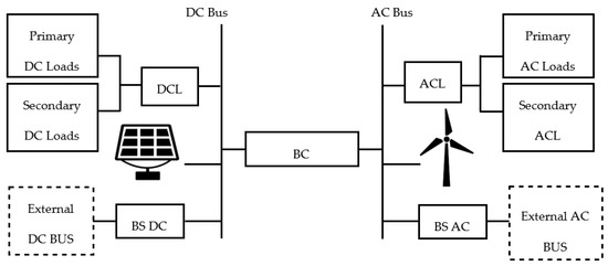
Figure 1.
The proposed Hybrid NG Architecture.
The primary objective of this study is to enhance the utilization of AC–DC renewable energy resources in each NG by leveraging load flexibility and the complementarity of RE resources. Secondly, the proposed approach aims to regulate the distribution of energy among different NGs to minimize dependence on the primary grid for power supply. This energy-sharing model enables individual energy resources to fulfill the energy requirements using renewable energy sources, and surplus energy generated by NGs is dispatched to the shared MG. By collaborating and sharing energy resources, users can reduce their energy bills and attain greater self-sufficiency.
This paper is organized as follows: In Section 2, some related works are reviewed and deeply analyzed. Section 3 presents the studied MG architecture and component modeling. The power balancing function is also presented. Section 4 gives details of the proposed energy management approach. Simulation results for both NGs and MGs are given in Section 5. Finally, the conclusion is presented in Section 6.
2. Related Work
In the literature, energy sharing in MG using MAS is rarely studied, unlike classical EMS, in both islanded and grid-connected MG configurations, with or without a storage system (SS). In a single MG or multi-microgrid system, researchers have focused on hierarchical control [6,7,8,9,10,11,12,13,14] or market-based approaches [9,10,11,12,15,16,17]. Table 1 provides a brief overview of some researchers’ work related to energy management systems based on MAS. Table 2 summarizes the literature on the type of installed renewable sources, centralized or decentralized controlling modes, and the type of hybrid loads, as compared to the proposed architecture in this paper, where the hybrid AC/DC loads are considered separately.

Table 1.
Reviews related to MAS-based MG EMS and energy sharing.
Table 2.
Source, load, and control type used in MG based on MAS.
The analysis of related works shows that many researchers focus on managing and optimizing energy in MG by selling/buying energy costs and SS [9,10,11,12,13,18]. However, other factors such as user behavior and energy optimization via sharing between buildings to reduce the use of CS, such as SS, diesel generators, and the main grid [6], should also be considered. Despite this, humans continue to exhibit disrespectful and irresponsible behavior in their daily lives. However, through individual contributions, humans could positively impact the energy management of any structure.
In this context, some authors have worked on islanded MG concepts in [14,20], while others have studied the grid-connected MG mode [10,11,13,18]. Additionally, the researchers in [9] took into account both OFF-grid and ON-grid MGs in their study. Some researchers also investigated energy sharing among buildings using MAS [7,11,13,17].
The authors in [21] proposed a DC-microgrid implementation that continuously controls the system using MATLAB Simulink, while discrete decisions are made by an agent developed via JADE. The proposed EMS is completed via MAS, which is developed under Jade, and MacsimJX establishes communication between Matlab Simulink and Jade.
The highlight of this study is to reduce the use of SS and energy supplied from the grid by using available RE sharing through MG entities based on the MAS platform. Indeed, the MAS is most appropriate for electrical systems that combine both distributed sources and loads, where each MG component has its interactive agent. Additionally, in a multi-nanogrid configuration, as shown in Figure 2, MAS facilitates inter-nanogrid (i.e., inter-building) renewable energy sharing. This energy sharing is based on both the flexibility of the AC–DC loads and their categorization into priority and non-priority loads, as discussed below. Furthermore, by leveraging auto-similarity, the number of NGs and MGs could be extended using the same problem-solving methodology and respond to the energy demand according to the implemented algorithm.
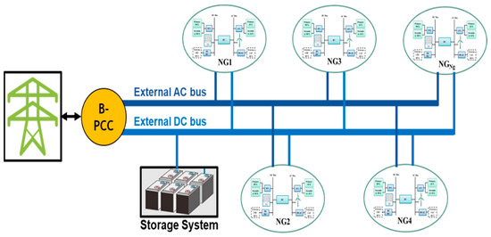
Figure 2.
The proposed decentralized MG architecture.
3. Material and Methods: The Proposed Microgrid Architecture
3.1. Microgrid Configuration
The proposed MG is made up of several buildings named NG (Figure 2). Mathematically, the MG is defined as the set of NGs, as shown in Equation (1).
As shown in Figure 2, all NGs (NGi=1, 2, …, Ng) are connected to the storage system (SS) and the main grid (G) via a DC bus and AC bus, respectively. Each NG is made up of PV and WT renewable sources that supply DC and AC loads, respectively (see Figure 1) [22,23,24]. However, if needed, DC sources can also serve as the AC loads (ACL) via an AC/DC bidirectional converter (BC), and the AC sources can supply the DC loads (DCL) through the same BC. This BC ensures energy balancing between the sources and the loads throughout the ith NG. The AC and DC bidirectional switches, named BS-AC and BS-DC, respectively, allow for the import/export of energy from external MG sources. Alternatively, NGi can provide energy to another NGj, SS, or to the main grid via external AC and/or DC buses. Additionally, NGi may consume the necessary energy from other MG entities via the same buses.
3.2. NanoGrid Description
3.2.1. Sources’ Description
In Reference [22], the power produced by the PV and WT sources is fully defined. In this paper, and denote the power produced by the solar panels and the WT, respectively, in the ith NG. The and the are given by Equations (2) and (3), respectively:
While for Equation (2), the is the rated power of the PV under the modulender standard test condition (KW), is the PV derating factor, is the solar radiation (KW/m2), is the incident radiation at standard test conditions (1 kW/m2), is the temperature coefficient (0.004 °C−1), is the PV cell operation temperature (°C), and is the PV cell temperature under standard test conditions (25 °C).
In Equation (3), the is the power coefficient, also known as Betz’s coefficient, which equals 0° in this case. In addition, and are the function of the tip speed ratio and the pitch angle, respectively, and is the air density (kg/m3), is the intercepting area of the rotor blades (m2), and is the average wind speed (m/s).
Therefore, Equation (4) depicts the cumulative renewable power generated in each ith NG. This power is determined by the contributions from the PV and WT sources, as outlined in Equations (2) and (3):
The positive parameters αi and βi, which describe the state of the renewable sources, range between 0 and 1. When αi = 0, it indicates that the installed WT is off, while αi = 1 means that the installed WT operates at its rated power. Similarly, βi = 0 depicts that the installed PV source is off, and βi = 1 indicates that the PV is active. When αi and/or βi are between 0 and 1, this indicates that the PV and/or WT systems are generating energy.
Thereby, the total energy produced during a period T in the ith NG, including the total PV produced energy and the total WT produced energy , is given by Equation (5):
3.2.2. Loads Description
Let be the set of loads used in the studied NGs. The set consists of AC and DC load types that are supplied by AC and DC sources, respectively. Moreover, L is split into AC and/or DC primary loads and AC and/or DC secondary loads as expressed in the following (6):
The loads set is made up of two subsets: primary AC loads, where the load’s set P is composed of two subsets: the primary AC loads subset and the primary DC loads subset as stated by Equation (7):
The total number of primary loads is denoted as N, such that:
Likewise, the load set consists of both secondary AC loads and secondary DC loads , which are expressed as follows:
The subsystem loads and , which represent the secondary loads in DC and AC modes, respectively, are stated in Equation (10):
Let M depicts the total number of secondary loads. Therefore, we have:
Based on the load’s categorization into the primary and secondary loads, the expression of the total energy consumed () in each ith NG during a period is denoted in the following Equation (12):
In Equation (13), denotes the energy used by both the primary and secondary DC loads at time slot T, as specified in Equation (14). Similarly, represents the energy required to meet the demand of both the primary and secondary AC loads at time slot T, as depicted in Equation (15).
where and represent the power requirements for the primary and secondary DC appliances, respectively. Similarly, and denote the power needs of the primary and secondary AC appliances.
3.2.3. Bidirectional Converter (BC)
However, different types of power converters can be utilized in both MG and NG applications. These devices are commonly employed in electrical renewable installations to facilitate the connection between PV and/or WT sources and buses or appliances [23,24]. The objective is to enhance the efficient integration of renewable sources, ensuring reliable load-supply capabilities and enabling complete control over voltage and power flow throughout the system buses. The bidirectional converter (BC) is the most frequently utilized device for enabling bidirectional power flow between the AC and DC buses [25].
In this work, the BC is used to simplify power exchange between the DC and AC sides (Figure 2). When the power generated by the PV panels is insufficient to meet the demand of the DC loads, and there is surplus AC power available compared to the demands of both the AC and DC loads, the required energy is transferred from the AC sources to the DC loads using the bidirectional converter. Similarly, power can be supplied from the DC side to the AC side using the same converter.
3.2.4. Bidirectional Switch (BS)
A bidirectional switch (BS) is a commonly used power device in power conversion systems [4]. This device is designed to facilitate the drawing or supplying of energy as required to or from an external source. In the proposed NG, there are two BS devices, with one allocated for the AC section and the other for the DC section. Each BS is responsible for toggling the extraction of energy from an external AC or DC bus on or off, based on the required energy and the energy supplied to fulfill the requirements of other MG appliances.
3.3. Microgrid Definition
3.3.1. Source Definition
According to Figure 1, the proposed MG has Ng nanogrids, and its structure is illustrated in Figure 2. Therefore, the total renewable energy (RE) in terms of MG photovoltaic power () and MG wind power () are defined in Equation (16).
Besides renewables sources, the MG total power can also be made up of SS and the main grid, as expressed in Equation (17).
where represents the SS installed power in the MG, and is the power provided from the main grid. The coefficients α, β, γ, and δ are positive parameters between 0 and 1. Specifically, α = 0 and β = 0 indicate that all WT and PV sources are turned off, while α = 1 and β = 1 mean that all WT and PV generators operate at their rated power. When α and/or β values are between 0 and 1, it implies the participation of WT and/or PV in energy generation.
The range −γmax < γ < γmax signifies that the SS can absorb or provide energy, meaning its state of charge (SoC) is between 20% and 80%. Otherwise, γ represents the rate of discharging or charging of the SS, depending on the MG state. The parameter δ indicates the percentage of power supplied by the main grid. δ = 0 and δ = 1 mean that no power or all power meeting the total MG demand is drawn from the grid, respectively. However, the grid should provide the required power to support the RE sources. The total energy produced by the MG during a period T is expressed in Equation (18).
3.3.2. Load Definition
Based on the load types in NGs, the MG loads are also made up of DC and AC loads, as expressed in the following Equation (19):
where and are respectively the DC and AC total MG loads, as shown in Equation (20):
The total energy consumed by the loads in the MG, denoted as , during a period is given by Equation (21):
3.4. Microgrid Energy Balancing Formulation
The main objective of this study is to minimize the power supplied by the main grid to the microgrid (MG) and reduce the usage of storage systems (SS). Therefore, the optimization approach considers the global energy sharing within the MG, based on local energy balancing in the NGs. This approach promotes the use of renewable sources to meet the load demands and enables energy sharing between intra-nanogrids and inter-nanogrids. This sharing of energy can eliminate the need for storage systems within each nanogrid, which is an innovative aspect of this proposed approach. This is particularly beneficial, considering the complexity and challenges associated with setting up and managing high-energy and high-power density storage systems. As a result, the energy sources, including renewable sources, storage systems, and the main grid, must collectively provide the required energy to meet the load demand within a given time slot T. The energy balance is represented by Equation (22).
According to Equations (16)–(18), the two terms of Equation (22) are expressed by Equations (23) and (24):
are positive parameters between 0 and 1, and is between and .
where and are respectively the NG power DC load and the NG power AC load. In another way, Equation (24) is reformulated in Equation (25):
In addition, the studied MG is a multi-source and multi-load system, where the energy management problem of the MG is defined as a multi-objective function (MOF), which is mathematically expressed as Equation (26).
At any given time, this multi-objective function (MOF) is subject to various physical and technical constraints, both at the microgrid (MG) level and the national grid (NG) level.
- At the MG level:
The constraints at the main grid (MG) level can be defined as follows:
C1.1: The total AC power generated must be below the installed wind turbine (WT) power.
C1.2: The total DC power generated must be below the installed photovoltaic (PV) power.
C1.3: The total power required by the microgrid (MG) loads should meet the minimum demand of primary MG loads while not exceeding the total MG loads.
C1.4: The convexity constraint.
C1.5: The upper limit for grid contribution.
C1.6: The maximum storage system contribution based on its storage capacity.
- At the nanogrid level:
Similarly, at the national grid (NG) level, there are certain constraints that need to be satisfied, which depend on the total installed power of renewable energy (RE) sources and the total loads in each NG. Therefore, the following constraints need to be taken into account:
The constraints at the main grid (NG) level can be defined as follows:
C2.1: The total available AC power must be less than the installed wind turbine (WT) power.
C2.2: The total available DC power must be less than the installed photovoltaic (PV) power.
C2.3: The convexity constraint, where represents the contribution rate from any external MG source to fulfill the power requirements of a specific NG.
C2.4: This rate of energy sharing should be below a maximum value in order to minimize the contribution from the main grid.
C2.5: The total power required by the loads in a given NG should meet the minimum demand of the primary NG loads while not exceeding the maximum total NG loads.
Besides, based on Equation (26), it is possible to achieve global microgrid (MG) energy management without considering the specifications and constraints of each individual NG (main grid).
The main focus of this study is to segment the optimization challenge of the global MG into distinct NG optimization methodologies through the utilization of an interactive hierarchical multi-agent system. This decomposition enables each NG to carry out its local energy balancing process considering its specific constraints related to the installed renewable capacity and load characteristics. At the higher level, the MG controller oversees the overall energy management by coordinating the sharing of energy between NGs and prioritizing the supply of required energy.
4. Theory: Proposed New Sustainable Energy Management Approach Based on MAS
The studied MG system comprises numerous NG, making centralized energy sharing schemes no longer the ideal solution. The specific nature of the NG and the MG lies in the connection of various heterogeneous and autonomous components that require coordination to optimize their involvement in the energy balance.
Each NG must be controlled through its local intelligent EMS. Energy exchange between the different NGs can be performed to ensure global energy balance through the MG system. In this way, MAS are well suited for energy management, where energy balancing can be distributed among several agents. In this case, the MAS is used due to its advantages in terms of operating costs, flexibility, ease of use, and inexpensiveness.
Energy management comes down to the sharing resources problem and controlling loads to preserve these energy sources. So, all NG entities will change their behaviors according to the local needs to ensure a global energy balance within the MG.
Agents in the MG have the capacity to control NG sources and loads, with each NG designated as an agent. Through the autonomy and self-adaptability of each agent, as well as their communication with neighboring agents, they are able to collaborate and coordinate effectively. Negotiations are typically used to achieve a balance of energy at both the local and global level.
The proposed architecture of the energy sharing system based on MAS utilizes a three-layer hierarchical model, as shown in Figure 3 and Figure 4, at the MG and NG levels, respectively.
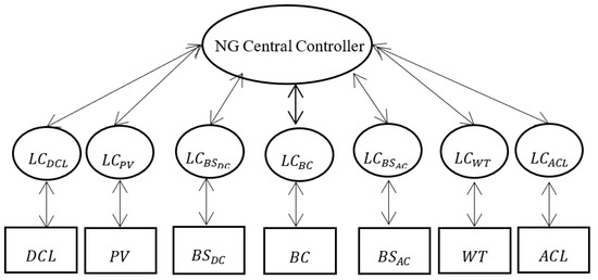
Figure 3.
The NG-proposed architecture based on layered MAS.
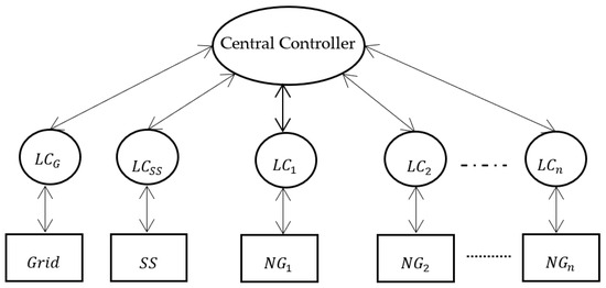
Figure 4.
MG architecture based on the MAS Layer.
In Figure 3, three-layers of MAS control strategies are established to manage the energy exchange:
- -
- On the bottom layer, there are the MG components: storage system (SS), main grid, and NGs. Those components will be controlled individually via their local agent.
- -
- At the intermediary layer, the intelligent local agents (LA) control the MG components directly. Thus, each LA perceives a limited environment and only controls specified elements, allowing them to react in real-time. So, each device has its local controllers () such as , which correspond respectively to the grid and the storage system, , and . Note that each agent manages the energy sharing within the corresponding and it is named the ith nano-energy management system ().
- -
- At the top layer, the central controller manages all local controllers and allows internal energy management sharing through the MG according to energy source availability. In other words, the centralized controller allows communication, management, and control of all MG devices to guarantee the intelligent and efficient use of renewable sources leading to an optimization of bills, energy, and users’ comfort. In the following, this controller is designated by a MG energy management system (µEMS).
Likewise, at the NGs level, three-layers are prominent (Figure 4). The lower layer consists of physical devices such as AC and DC renewable sources, AC and DC loads, the bidirectional converter, and bidirectional switches, as depicted in Figure 2. Each device is controlled by its agent. At the upper layer, the central controller will supervise and control the energy share through an NG. This controller also contributes to the optimal energy schedule in the MG. The description and function of all the used agents are presented as follows:
- -
- µEMS Agent: receives information from the storage system agent and the grid agent, and information about all NG agents that participate in the energy sharing through the same MG. Also, this agent receives information about the resulting state of each NG, the charge/discharge storage state, and the availability of the main grid to decide on the suitable solution of any energy dispatching scenarios. The µEMS agent represents the central controller agent that not only receives information, but also makes decisions and gives the orders to the other local controllers to make the accurate decision.
- -
- Grid Agent (G Agent): while the grid may show some unavailable time, the grid agent gives information about the network’s state.
- -
- Storage System Agent (SS Agent): refers to the storage state in terms of SoC and reports the state information to the global µEMS.
- -
- ƞEMS Agent: depicts the central controller in each NG.
This agent collects information and requests from the other agents in the same building, allowing it to make a decision and manage the whole of the NG’s sources and loads. This agent is also responsible for delivering information about the building’s energy state in terms of requested and available energy via the local agent controller of the NG’s entities. The system aims to optimize the indoor energy-scheduling scheme and then inform the µEMS about the NG state.
4.1. Multi-Agent System Model
The energy sharing process is approached as a distributed optimization strategy that relies on intelligent and interactive agents. The objective is to optimize the scheme in order to minimize reliance on the main grid and subsequently decrease consumers’ bills. Moreover, the utilization of the storage system is limited to urgent circumstances or when it is essential for preserving its longevity within the microgrid (MG). To achieve this, cooperation between NG agents and MG agents is essential for a successful energy exchange. In this study, a holonic multi-agent system (MAS) is proposed, employing a nested hierarchical structure where the agents are composed of sub-agents.
The proposed MAS is depicted in Figure 5, illustrating the management of energy sharing within the MG. This model adheres to the composite design pattern, dividing the agents into two categories: terminal agents and composite agents. Composite agents can either consist of multiple terminals or represent an infinite hierarchy. Two types of composite agents are present: the µEMS agent and the ƞEMS agent. Terminal agents consist of functional agents within the control panel, namely: the Bidirectional Converter Agent (BC Agent), Bidirectional Switch Direct Current Agent (BSDC Agent), Direct Current Load Agent (DCL Agent), Photovoltaic Panel Agent (PV Agent), Bidirectional Switch Direct Current Agent (BSAC Agent), Wind Turbine Agent (WT Agent), and Alternative Current Load (ACL) Agent.
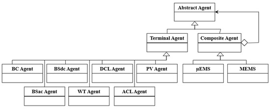
Figure 5.
Multi-Agent System model structure.
This paper develops the MAS within the JADE environment and utilizes MATLAB/Simulink to create and simulate the distribution microgrid. The co-simulation platform between Simulink and JADE is required for the MG model and MAS data transmission. MAC-SimJX facilitates the connection between JADE and MATLAB, enabling interaction between the power system and its integrated multi-agent communication layer, as shown in Figure 6a. The MAC-SimJX platform employs the Pipes protocol under Windows to facilitate the data exchange between the MG model simulation in Simulink and the multi-agent system in JADE. Data transfer from JADE to MACsim is accomplished via TCP/IP.
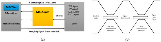
Figure 6.
Communication model. (a) The process model of the communication between MATLAB and JADE. (b) Outline of the communication pathway process.
JADE enables MACSimJX to receive data through the MACSim interface and transmit them to the relevant agent for processing. The agent is specifically designed to optimize the incoming data. Figure 6b outlines the communication pathway connecting the Simulink model with the agent task force (ATF) and agent environment (AE).
4.2. Interaction Diagram of Agent
The proposed approach is based on a communication and coordination pattern according to an agent interaction protocol. Any agent can perform in parallel or independent of any other agent. At the NG level, an agent is required to carry out self-management of sources and loads to ensure energy balance in its own NG. The interaction is between the ƞEMS agents, grid, and SS and the central agent µEMS. When the intelligent agent receives all the necessary information and data, the intelligent agent begins with the process treatments.
5. Results and Discussion
To validate the feasibility of the MAS-based EMS discussed in the preceding sections, we examine a microgrid (MG) implemented within the ENSET campus [22]. This campus is made up of four buildings, where each building has its own sub-grid named NG. The four NG are designed according to Figure 1′s architecture to allow prospective energy sharing through the MG. The MG operates in a grid-connected mode. The MG has a daily available capacity of 613.1 kWh. The simulation was carried out considering the wind and solar data provided by a meteorological station in Mohammedia, Morocco (3°41′23″ N, 7°23′23″ W). All information about power consumption was collected carefully to simulate different situations. The start and end date of the data collections occurred during the year 2020. However, the study was prudently and daily analyzed in the whole month of May 2020. The reason for choosing this dataset is the need of testing the performance, robustness, and effectiveness of the proposed solution in such types of buildings, and to demonstrate the availability of this system for any type of buildings that will be studied in the next work.
This section is divided into two parts. The first part presents the results of the NG, highlighting the details of its sources and loads in Table 3 and Table 4. The second part provides the results of the microgrid (MG), showcasing the daily average production and consumption of the studied NGs in Table 5 and Table 6.
Table 3.
The NGs’ total production and demand energy details.
Table 4.
The NGs’ average daily production and demand energy details.
Table 5.
Nanogrid power state.
Table 6.
The power given by NG in surplus state to NG in deficit state.
Figure 7 depicts the production and demand variation through NG1, NG2, NG3, and NG4. The daily production in all NGs follows the similar evolution because of the same geographic localization of the studied site. The difference will be shown in terms of the installed power capacity in each NG according to its own power demand.
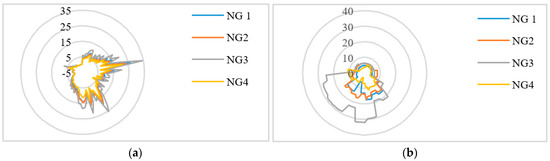
Figure 7.
Total daily energy production and demand of the nanogrids (NGs). (a) Daily renewable power generated by the NGs. (b) Daily energy demand of the NGs.
5.1. Nanogrids’ Energy Compensation
The profile of the four NGs is almost identical, owing to the similar location and climatic conditions. In this part, the illustration in Figure 8, Figure 9, Figure 10 and Figure 11 represents the daily need of each NG. So, the daily energy requirement can be compensated via an energy exchange through the NGs or by supplying energy from CS. Also, the figures depict that the excess energy can be delivered to the CS. In addition, all the energy requested and surplus during the 24 h of the four case studies is represented in Figure 12.
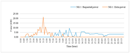
Figure 8.
NG1 requested and excess power profile for 24 h.
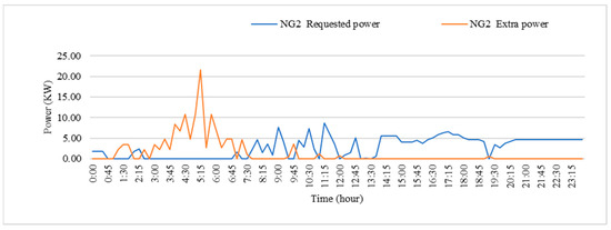
Figure 9.
NG2 requested and excess power profile for 24 h.
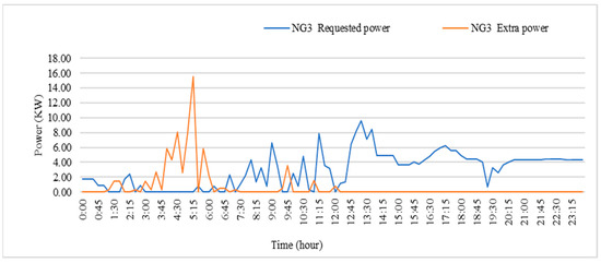
Figure 10.
NG3 requested and excess power profile for 24 h.
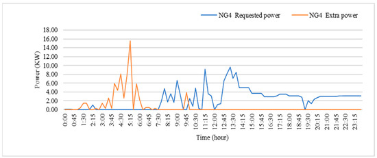
Figure 11.
NG4 requested and excess power profile for 24 h.
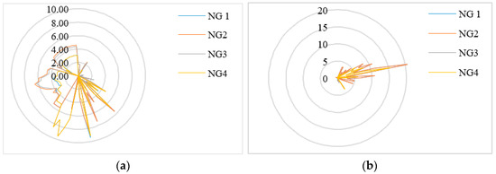
Figure 12.
The daily energy surplus and demand in the four studied nanogrids (NGs). (a) The power profile of the four nanogrids (NGs) during 24 h period. (b) The surplus power profile of the four nanogrids (NGs) during 24 h period.
5.2. Compensation
To illustrate the energy compensation between the nanogrids (NGs), we consider six time slots as an example to demonstrate the instantaneous behavior of each NG, as shown in Table 5. This information, along with the available power values, enables the system to determine where to request energy and to whom it should be exported.
For instance, from 5:15 a.m. to 5:30 a.m., all NGs have met their power requirements and can share their surplus power through the external bus to charge the storage system or inject additional energy into the main grid. At 5:30 a.m., NG1 and NG2 have a surplus of 2.65 KW (green color), while NG3 requires 0.79 KW (yellow color). Meanwhile, NG4 shows energy self-sufficiency (blue color) at this time slot.
Based on these NG behaviors, the intelligent energy management system (EMS) makes decisions, which are depicted in Table 6. The EMS determines that approximately 29.84% of NG1’s power should be used to fulfill NG3’s needs at 5:30 a.m. Additionally, NG1 provides 29.08% of its power to NG3 at 6:15 a.m. and exports 70.92% to the external bus, which includes both the storage system and the main grid. At 7:15 p.m., NG2 is selected to supply NG3 with 27.57% of its excess power. Figure 13 depicts the results of energy compensation among the four NGs, indicating the deficit or surplus state of the microgrid (MG) at any given time slot within 24 h.
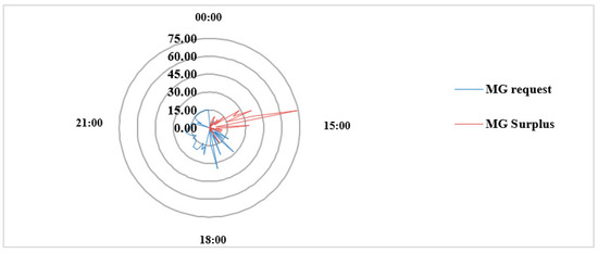
Figure 13.
MG requested and exported energy from/to CS.
5.3. Cost Impact in NG Building Case Study
Figure 14 illustrates the energy bills of each NG before and after implementing the proposed solution during May 2020. It should be noted that these savings were achieved prior to the application of the energy sharing solution between the NGs. After utilizing the energy sharing approach based on MAS, the energy bills decreased to 4230.67 MAD compared to 23,961.27 MAD, before implementing any solutions. This represents remarkable savings of approximately 82.34%, highlighting the effectiveness and robustness of the proposed solution.

Figure 14.
Energy cost estimates for the proposed structure.
In Figure 15, we observe the monthly electricity bill patterns of the four NGs throughout the year 2020 using the proposed system. It is evident that the activity of the NGs fluctuates depending on climate changes and user behavior. For instance, during September and June, when academic activities are at their peak with students and staff occupying various buildings, the energy demand is higher. Conversely, during July and August, the activity reaches its minimum level of usage.
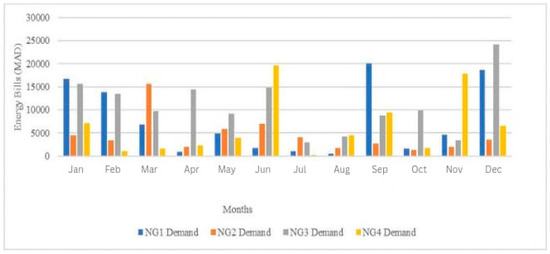
Figure 15.
Monthly electricity bills result (2020).
Furthermore, the last figure (Figure 16) compares the electricity bill patterns of the buildings during the same period with the previous year (2019). The results demonstrate energy savings ranging from 40% to 66% compared to the previous year.
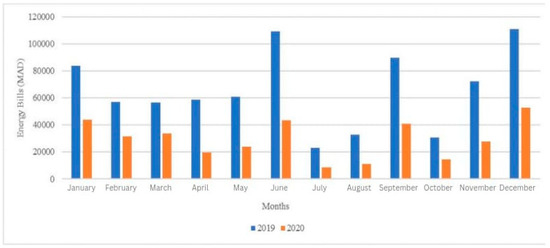
Figure 16.
Electricity bill behaviors before and after using the proposed solution.
6. Conclusions
This paper presents a novel energy management system for microgrids that utilizes a multi-agent system (MAS). The proposed EMS coordinates four distributed energy management subsystems to achieve overall energy balancing in the microgrid. Its objective is to reduce energy bills and investments while promoting energy reliability and sustainability at low costs. The MAS is developed with a three-level structure consisting of the device layer, local controller layer, and central controller layer. The goal of using the same control model in both the microgrid and the main grid systems is to ensure consistent treatment across all system entities. The results demonstrate the effectiveness of the proposed EMS, which achieved energy savings and sharing in the microgrid, as well as self-compliance in the main grid by leveraging load flexibility. According to the results obtained in this study, our energy sharing system resulted in over 82.34% energy savings.
This case study presents a modular solution that contributes to reducing the significant reliance on conventional sources (CS), particularly traditional energy sources (SS). It also enables the determination of actual energy consumption in new eco-energy concepts. Furthermore, a new generation of data on power consumption will grow with the concept of power sharing, a new energy behavior that serves to optimize consumption and better-manage energy in a building. This, in turn, improves energy efficiency and reduces CO2 emissions. In the future, the significant need for batteries to store energy will be reduced using this concept, and even the sizing of building consumption will be optimized using this concept, which will enable us to know the actual consumption. This paper focuses only on academic buildings in terms of energy sharing. Although this approach is valid for any building, we need further studies and verification. In future work, we will focus on residential and commercial buildings to demonstrate the efficiency of our new approach. Additionally, we scheduled to conduct a comparative study for different implementations with all types of buildings to confirm the system’s effectiveness and performance.
A new work showcasing JADE’s programming for agents in various buildings will demonstrate the self-similarity of the solution. The work will cover the decentralization and distribution of decision-making processes among autonomous agents, their individual objectives, and the evolution of global objectives. Additionally, the work will evaluate the proposed method’s behavior under variations in active and reactive power loads.
Author Contributions
Conceptualization, M.H.; Methodology, M.H., A.R. and O.B.; Validation, A.R. and O.B.; Formal analysis, M.H.; Writing—original draft, M.H.; Writing—review & editing, A.R. and O.B.; Supervision, A.R. and O.B. All authors have read and agreed to the published version of the manuscript.
Funding
This research received no external funding.
Institutional Review Board Statement
Not applicable.
Informed Consent Statement
Not applicable.
Data Availability Statement
Not applicable.
Conflicts of Interest
The authors declare no conflict of interest.
References
- Mezouari, A.; Elgouri, R.; Igouzal, M.; Alareqi, M.; Mateur, K.; Dahou, H.; Hlou, L. A New Photovoltaic Energy Sharing System between Homes in Standalone Areas. Int. J. Electr. Comput. Eng. IJECE 2018, 8, 4855. [Google Scholar] [CrossRef]
- AlSkaif, T.; Zapata, M.G.; Bellalta, B.; Nilsson, A. A distributed power sharing framework among households in microgrids: A repeated game approach. Computing 2017, 99, 23–37. [Google Scholar] [CrossRef]
- Fleischhacker, A.; Auer, H.; Lettner, G.; Botterud, A. Sharing Solar PV and Energy Storage in Apartment Buildings: Resource Allocation and Pricing. IEEE Trans. Smart Grid 2019, 10, 3963–3973. [Google Scholar] [CrossRef]
- Hong, Y.; Goel, S.; Liu, W.M. An efficient and privacy-preserving scheme for P2P energy exchange among smart microgrids: Privacy-preserving energy exchange among smart microgrids. Int. J. Energy Res. 2016, 40, 313–331. [Google Scholar] [CrossRef]
- Hamidi, M.; Raihani, A.; Youssfi, M.; Bouattane, O. A new modular nanogrid energy management system based on multi-agent architecture. Int. J. Power Electron. Drive Syst. IJPEDS 2022, 13, 178. [Google Scholar] [CrossRef]
- Akter, M.N.; Mahmud, A.; Oo, A.M.T. A Hierarchical Transactive Energy Management System for Energy Sharing in Residential Microgrids. Energies 2017, 10, 2098. [Google Scholar] [CrossRef]
- Carli, R.; Dotoli, M. A Decentralized Control Strategy for the Energy Management of Smart Homes with Renewable Energy Exchange. In Proceedings of the 2018 IEEE Conference on Control Technology and Applications (CCTA), Copenhagen, Denmark, 24 August 2018; IEEE: Piscataway, NJ, USA, 2018; pp. 1662–1667. [Google Scholar] [CrossRef]
- Liu, T.; Tan, X.; Sun, B.; Wu, Y.; Guan, X.; Tsang, D.H.K. Energy management of cooperative microgrids with P2P energy sharing in distribution networks. In Proceedings of the 2015 IEEE International Conference on Smart Grid Communications (SmartGridComm), Miami, FL, USA, 2–5 November 2015; IEEE: Piscataway, NJ, USA, 2015; pp. 410–415. [Google Scholar] [CrossRef]
- Esfahani, M.M.; Hariri, A.; Mohammed, O.A. A Multiagent-Based Game-Theoretic and Optimization Approach for Market Operation of Multimicrogrid Systems. IEEE Trans. Ind. Inform. 2019, 15, 280–292. [Google Scholar] [CrossRef]
- Eddy, Y.S.F.; Gooi, H.B.; Chen, S.X. Multi-Agent System for Distributed Management of Microgrids. IEEE Trans. Power Syst. 2015, 30, 24–34. [Google Scholar] [CrossRef]
- Jiang, W.; Yang, K.; Yang, J.; Mao, R.; Xue, N.; Zhuo, Z. A Multiagent-Based Hierarchical Energy Management Strategy for Maximization of Renewable Energy Consumption in Interconnected Multi-Microgrids. IEEE Access 2019, 7, 169931–169945. [Google Scholar] [CrossRef]
- Xiong, L.; Li, P.; Wang, Z.; Wang, J. Multi-agent based multi objective renewable energy management for diversified community power consumers. Appl. Energy 2020, 259, 114140. [Google Scholar] [CrossRef]
- Denysiuk, R.; Lilliu, F.; Vinyals, M.; Recupero, D. Multiagent System for Community Energy Management. In Proceedings of the 12th International Conference on Agents and Artificial Intelligence, Valletta, Malta, 22–24 February 2020; SCITEPRESS—Science and Technology Publications: Setúbal, Portugal, 2020; pp. 28–39. [Google Scholar] [CrossRef]
- Lee, W.-P.; Choi, J.-Y.; Won, D.-J. Coordination Strategy for Optimal Scheduling of Multiple Microgrids Based on Hierarchical System. Energies 2017, 10, 1336. [Google Scholar] [CrossRef]
- Kuruseelan, S.; Vaithilingam, C. Peer-to-Peer Energy Trading of a Community Connected with an AC and DC Microgrid. Energies 2019, 12, 3709. [Google Scholar] [CrossRef]
- Klein, L.P.; Krivoglazova, A.; Matos, L.; Landeck, J.; de Azevedo, M. A Novel Peer-To-Peer Energy Sharing Business Model for the Portuguese Energy Market. Energies 2019, 13, 125. [Google Scholar] [CrossRef]
- Monsberger, C.; Fina, B.; Auer, H. Profitability of Energy Supply Contracting and Energy Sharing Concepts in a Neighborhood Energy Community: Business Cases for Austria. Energies 2021, 14, 921. [Google Scholar] [CrossRef]
- EL Bourakadi, D.; Yahyaouy, A.; Boumhidi, J. Multi-agent system based sequential energy management strategy for Micro-Grid using optimal weighted regularized extreme learning machine and decision tree. Intell. Decis. Technol. 2020, 13, 479–494. [Google Scholar] [CrossRef]
- Perera, M.; Disanayaka, R.; Kumara, E.; Walisundara, W.; Priyadarshana, H.; Ekanayake, E.; Hemapala, K. Multi Agent Based Energy Management System for Microgrids. In Proceedings of the 2020 IEEE 9th Power India International Conference (PIICON), Sonepat, India, 28 February–1 March 2020; IEEE: Piscataway, NJ, USA; pp. 1–5. [Google Scholar] [CrossRef]
- Keshta, H.E.; Ali, A.A.; Saied, E.M.; Bendary, F.M. Real-time operation of multi-micro-grids using a multi-agent system. Energy 2019, 174, 576–590. [Google Scholar] [CrossRef]
- Boudoudouh, S.; Maâroufi, M. Multi agent system solution to microgrid implementation. Sustain. Cities Soc. 2018, 39, 252–261. [Google Scholar] [CrossRef]
- Raihani, A.; Khalili, T.; Rafik, M.; Hicham, M.; Bouattane, O. Towards a Real Time Energy Management Strategy for Hybrid Wind-PV Power System based on Hierarchical Distribution of Loads. Int. J. Adv. Comput. Sci. Appl. 2019, 10. [Google Scholar] [CrossRef]
- Indragandhi, V.; Logesh, R.; Subramaniyaswamy, V.; Vijayakumar, V.; Siarry, P.; Uden, L. Multi-objective optimization and energy management in renewable based AC/DC microgrid. Comput. Electr. Eng. 2018, 70, 179–198. [Google Scholar] [CrossRef]
- Watil, A.; El Magri, A.; Raihani, A.; Lajouad, R.; Giri, F. Multi-objective output feedback control strategy for a variable speed wind energy conversion system. Int. J. Electr. Power Energy Syst. 2020, 121, 106081. [Google Scholar] [CrossRef]
- Maqueda, E.; Rodas, J.; Toledo, S.; Gregor, R.; Caballero, D.; Gavilan, F.; Rivera, M. Design and Implementation of a Modular Bidirectional Switch Using SiC-MOSFET for Power Converter Applications. Act. Passive Electron. Compon. 2018, 2018, 4198594. [Google Scholar] [CrossRef]
Disclaimer/Publisher’s Note: The statements, opinions and data contained in all publications are solely those of the individual author(s) and contributor(s) and not of MDPI and/or the editor(s). MDPI and/or the editor(s) disclaim responsibility for any injury to people or property resulting from any ideas, methods, instructions or products referred to in the content. |
© 2023 by the authors. Licensee MDPI, Basel, Switzerland. This article is an open access article distributed under the terms and conditions of the Creative Commons Attribution (CC BY) license (https://creativecommons.org/licenses/by/4.0/).