Article

Optimal Design and Mean Stress Estimation of Modular Metamaterials Inspired by Burr Puzzles

1
State Key Laboratory of Precision Blasting, Jianghan University, Wuhan 430056, China
2
Hubei Key Laboratory of Blasting Engineering, Jianghan University, Wuhan 430056, China
3
School of Aeronautics and Astronautics, Sun Yat-sen University, Shenzhen 518107, China
4
Department of Aeronautics and Astronautics, Fudan University, Shanghai 200433, China
*
Authors to whom correspondence should be addressed.
Sustainability 2023, 15(18), 13963; https://doi.org/10.3390/su151813963
Submission received: 24 August 2023 / Revised: 18 September 2023 / Accepted: 19 September 2023 / Published: 20 September 2023

Abstract

:
Modular impact-resistant metamaterials inspired by burr puzzles were recently proposed to combine flexibility, efficiency and adaptivity, which were also beneficial for sustainability in engineering protection. However, the optimal design remains to be explored and the mean stress cannot be effectively estimated. To break these limits, a stiffness-enhanced strategy is implemented to enhance the crashworthiness, and the relation between the mechanical behavior of metamaterials and locking points is revealed. The average thickness of all modules in the metamaterial is denoted by tave, and the thickness ratio of axially loaded to laterally loaded modules is denoted by y. From the experimental and simulation results, the mean stress of the metamaterials significantly increases with tave and y, while the deformation mode is gradually transformed into an inefficient global buckling mode and impairs the crashworthiness when ψ 4 . ψ = 3 can be taken as the optimal design of metamaterials, which can increase the specific energy absorption SEA, energy absorption efficiency h and mean stress sm, respectively, by 62.4%, 44.2% and 57.6% compared to the regular design ( ψ = 1 ). On this basis, we develop a universe method to estimate the mean stress of the metamaterials with a relative error less than 9.6%, and a guideline for their design and application in engineering fields is summarized. This research opens a new avenue for broadening the design and applications of modular metamaterials in engineering applications.

1. Introduction

Sudden impacts cause great damage to lives and devices, and therefore the development of impact-resistant devices plays a paramount role in engineering fields, including aerospace, road traffic, and navigation [1,2,3]. Cellular materials have attracted great attention from researchers because of their desirable properties [4,5,6,7], which have been extensively studied by experiments, numerical simulations and theoretical analysis. Among them, honeycombs are widely used due to their exceptional crashworthiness under out-of-plane loads [8,9,10], while sharp stress peak results in great damage to safety [9,10,11,12]. Their initial peak can be attenuated under in-plane loads, while the bearing capacity is significantly weaker [12,13,14]. To overcome these drawbacks, grooves or creases can be applied to eliminate the impact peak [15,16,17], and reinforcing walls or filling material can be embedded to promote the stiffness [18]. In comparison, foams are applicable to complex load environments due to their approximate isotropic stiffness, and their porosity can be designed on demand to tune stiffness [19,20,21]. Contrary to foams with disordering cells, lattices are defined as reticulated materials composed of repeating unit cells, which continuously develop relying on additive manufacturing [22,23,24,25]. Although the cellular materials trigger great promotion of mechanical properties, they mostly lack flexibility and adaptivity because their properties cannot be adjusted after manufacture.
Mechanical metamaterials display unprecedented properties by designing microstructures [26,27,28,29], which also play increasingly vital roles in electricity, optics, acoustics, etc. [30,31,32,33,34]. The deformation constraints among the components can be specially decoupled to promote their tunability [35,36]. For instance, Pan et al. employed bistable units to construct 3D pixel metamaterials [35], and Li et al. used soft elastomer and a stiff frame to form reusable architected metamaterials [37]. However, extra constraints are commonly required to connect the modules, which will result in extra costs in time and labor to impair the modifiability. To remove these constraints, a series of discretely assembled self-locked devices have been proposed [38,39,40,41,42,43], in which the components are specially designed to interlock with each other. Thus, modifiability to respond to emergencies can be obtained after disassembling and reconfiguring. However, the load capacity of the above-mentioned adjustable devices is currently not comparable to traditional cellular materials, and how to combine desirable crashworthiness and tunability poses a challenge for material and structure designs. To achieve this goal, modular metamaterials inspired by burr puzzles were proposed recently [44]. The metamaterial is discretely assembled by thin-walled modules with grooves, and omnidirectional self-locking capability is obtained for convenient assembling and disassembling processes. The crashworthiness of the metamaterials approaches out-of-plane loaded honeycombs, and their on-demand property tunability after manufacture is demonstrated to help adapt to the load environment. More critically, the undeformed modules can be reused repeatedly even when the metamaterials are deformed severely, which is highly conducive to engineering sustainability. Nevertheless, their mechanical properties can be further improved, and the mean stress cannot be effectively estimated in existing studies.
To this end, stiffness-enhanced design is implemented for modular metamaterials to enhance the crashworthiness without increasing the equivalent density or inducing a sharp stress peak, which is validated by experiments and finite element modelling (FEM) simulations. Considering both the costs and the load capacity that face major engineering projects, the specimens are manufactured by a three-dimensional (3D) printing method using 316L stainless steel, and the simulations are carried out by ABAQUS/Explicit. The optimal designs of the metamaterials and the locking points are explored, and the relation between the mechanical behavior of metamaterials and locking points is revealed. On this basis, a universe method is developed to accurately estimate the mean stress of the metamaterials. This work provides an example of estimating the mechanical behavior of complex engineering structures, and may shed light on providing the guidelines for the design and application of energy absorbers in engineering fields.

2. Models and Methods

2.1. Models

As shown in Figure 1, the burr puzzle-inspired modular metamaterials are discretely assembled by thin-walled modules without constraints, and each module is periodically distributed by unit cells [44]. Each unit cell is comprised of four identical isosceles triangular and two identical rectangular planes, and a groove is formed between every two adjacent unit cells. The groove number of the module is denoted by n (n ≥ 2), i.e., n = 6 in Figure 1. Every six modules can orthogonally assemble as a locking point with self-locking capability, which can be flexibly assembled and disassembled. For metamaterials with multiple locking points, omnidirectional self-locking capability is obtained to respond to complex loading environments in emergencies. Therefore, the necessity for internal fasteners or external constraints during installation is removed to reduce the costs and enhance the modifiability. Furthermore, the scrap rate is reduced to enhance sustainability, because the undamaged modules can be reused even if the other modules deform severely. More critically, by utilizing tougher axially loaded modules and lightweight laterally loaded modules, the metamaterial stiffness in a specific direction can be enhanced and the tunable range of mechanical properties can be promoted without increasing the equivalent density. Herein, axially and laterally loaded modules are respectively defined as modules with an axial direction parallel and a perpendicular to load direction.
To make it clear, the stiffness-enhanced and impaired modules are respectively marked in blue and grey (Figure 1). In this paper, the module stiffness is tuned by the wall thickness as an illustration. The average thickness of all modules in each metamaterial is denoted by tave, and the thickness of axially and laterally loaded modules is respectively denoted by t1 and t2. It satisfies that t 2 t a v e t 1 and t 1 + 2 t 2 = 3 t a v e . The thickness ratio ψ   ψ 1 is defined as follows to quantify the degree of the stiffness-enhanced design
ψ = t 1 t 2
and it satisfies that ψ = 1 when the stiffness of the metamaterials is unenhanced.

2.2. Experimental Details

To verify the performance promotion by stiffness-enhanced design and reveal its mechanical mechanism, quasi-static experiments on metamaterials and locking points under various parameters are separately carried out. A few regular module specimens in each metamaterial were replaced by triangular prism modules to further decrease the assembling difficulties, and it had been proven in previous work that the mechanical properties were almost unaffected by this simplified design [44].
Each complete module specimen was manufactured a by 3D printing method using 316L stainless steel, and the material properties of 316L stainless steel of the printed specimens were tested in previous work [10,44]; these were also employed in this study as listed in Table 1. The selective laser melting (SLM) technique was employed using an iSLM280 metal 3D printer (Figure 2a), while the detailed manufacturing process was introduced in previous work [10]. Each metamaterial specimen was discretely assembled by 42 regular and 12 triangular prism module specimens with n = 6, and 27 discrete locking points were formed as shown in Figure 4a. Each locking point specimen was formed by six regular module specimens with n = 2, as shown in Figure 8. The concrete assembling process can be found in previous work [44]. The designed basic parameters of the metamaterial and locking point specimens are respectively listed in Table 2 and Table 3, and their mass is respectively denoted by mmeta and mlock. The experimental results of the metamaterial and locking point specimens are respectively provided in Section 3.1 and Section 3.2.
Each specimen was placed between a loading plate and a fixed supporting plate, and the loading plate crushed the specimen at a speed of 1 mm/min to reduce the dynamic effects. Quasi-static crushing of each metamaterial specimen is carried out by a TIYINS-HCM206B test machine (Figure 2b), the measuring range of which is up to 2000 kN. Quasi-static crushing of each locking point specimen is conducted by an MTSE 45.305 test machine (Figure 2c), the measuring range of which is 300 kN. The crushing load and displacement of the loading plate were both recorded per 0.05 s, and at least 30.000 data points were extracted in the entire crushing process. All data points were used in the mechanical analysis to ensure the creditability. The deformation of the specimens was recorded by a high-definition camera.

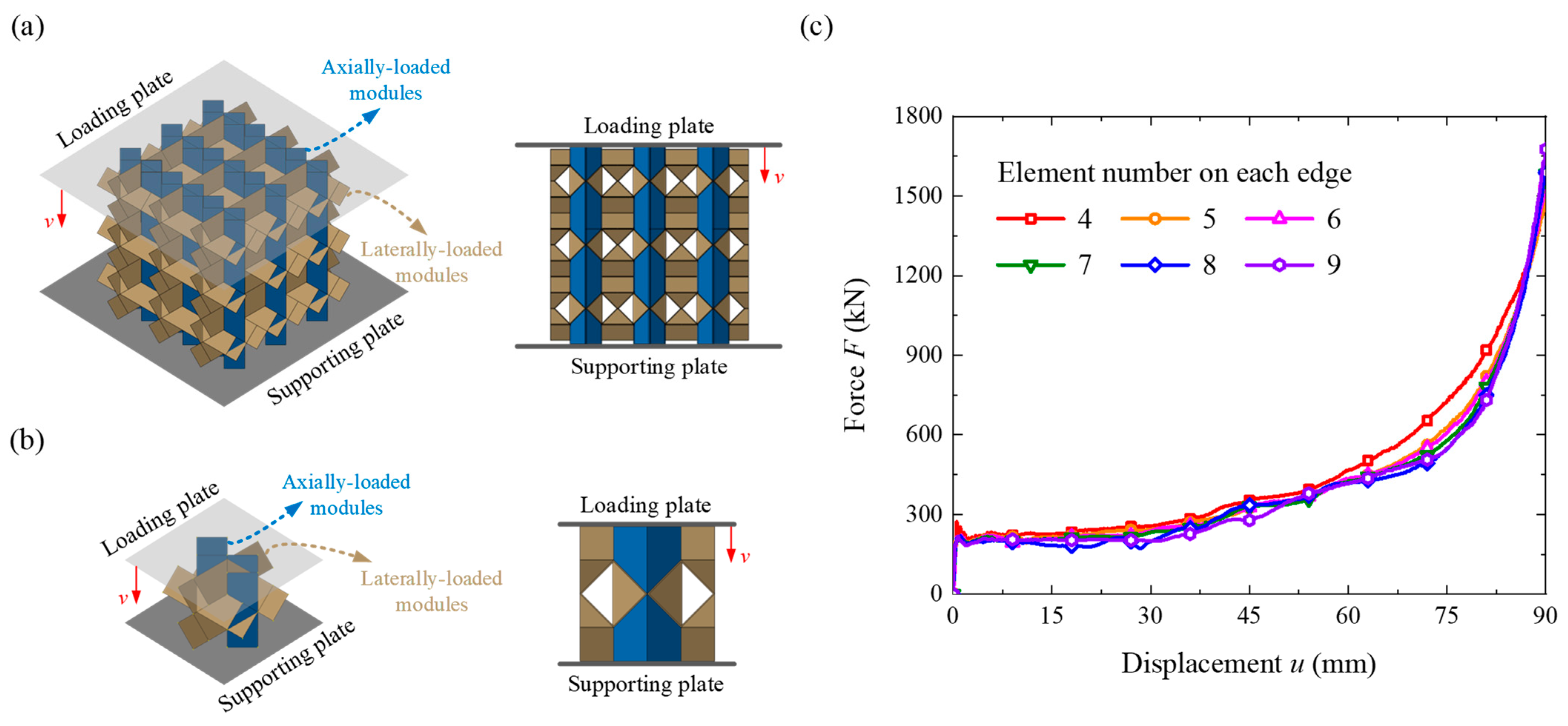
2.3. FEM Simulation Details

The finite element simulation is carried out by ABAQUS/Explicit in this work. Each model is placed on a fixed rigid supporting plate and crushed by a rigid loading plate with a constant velocity of v (Figure 3a,b). The lateral movement of the model is unconstrained, while the size of the loading and supporting plates is large enough to avoid its slipping away from the boundaries. Each complete module and the two plates are modeled using the shell element S4R in ABAQUS, and the assembling patterns of the modules are the same as the specimens. The contact properties between the surfaces are set as “general” and “hard” contacts, and the friction coefficient is set as 0.05 [45]. The material is also adopted as 316L stainless steel and bilinear elastic-plastic constitutive models are employed in the simulation with properties listed in Table 1. The geometry parameters of the modules are adopted as in Table 2 and Table 3. The data points of the load and displacement of the loading plate are exported to more than 500 groups, which are all used in the mechanical analysis to ensure its creditability. The von Mises stress or effective plastic strain (PEEQ) nephograms of the models are extracted to capture the deforming details. The mesh convergence study is carried out via extracting the force-displacement curves of the metamaterials (Figure 3c), and the element number on each edge is set as 6 to ensure the FEM accuracy of this study. Herein, F and u are respectively defined as the crushing force and displacement.

2.4. Key Performance Indicators

The equivalent density of the metamaterial or locking point ρ e q is calculated by ρ e q = m / L W H , where m, L, W, and H are, respectively, its mass, length, width, and height. The effective stress σ e f and strain ε e f are respectively calculated by σ e f = F / L W and ε e f = u / H . In this paper, specific energy absorption SEA, energy absorption efficiency h and mean stress σ m are adopted as key indicators to evaluate the energy absorption performance. The real-time energy absorption efficiency η ε e f is defined by
η ε e f = 0 ε e f σ e f ε e f d ε e f σ e f ,   m a x ε e f
which can determine the representative strain of densification εcd by
d η ε e f d ε e f ε e f = ε c d = 0
at which the efficiency η ε e f reaches the maximum h on the efficiency-strain curve. The effective stroke Sef is calculated by
S e f = ε c d H
and the effective stroke ratio ESR equals εcd. The total energy absorption EA can be calculated by
E A = 0 S e f F d u
and the specific energy absorption SEA is defined as the energy absorption per unit mass
S E A = E A m
The mean stress sm is defined here to evaluate the average load-carrying capacity, which can be expressed as
σ m = E A L W S e f

3. Results and Discussions

To prove the effect of the stiffness-enhanced design and effectively estimate the plateau stress, the results from quasi-static compressive experiments and FEM simulations are analyzed and discussed. On this basis, a parametric study is carried out to further improve its crashworthiness.

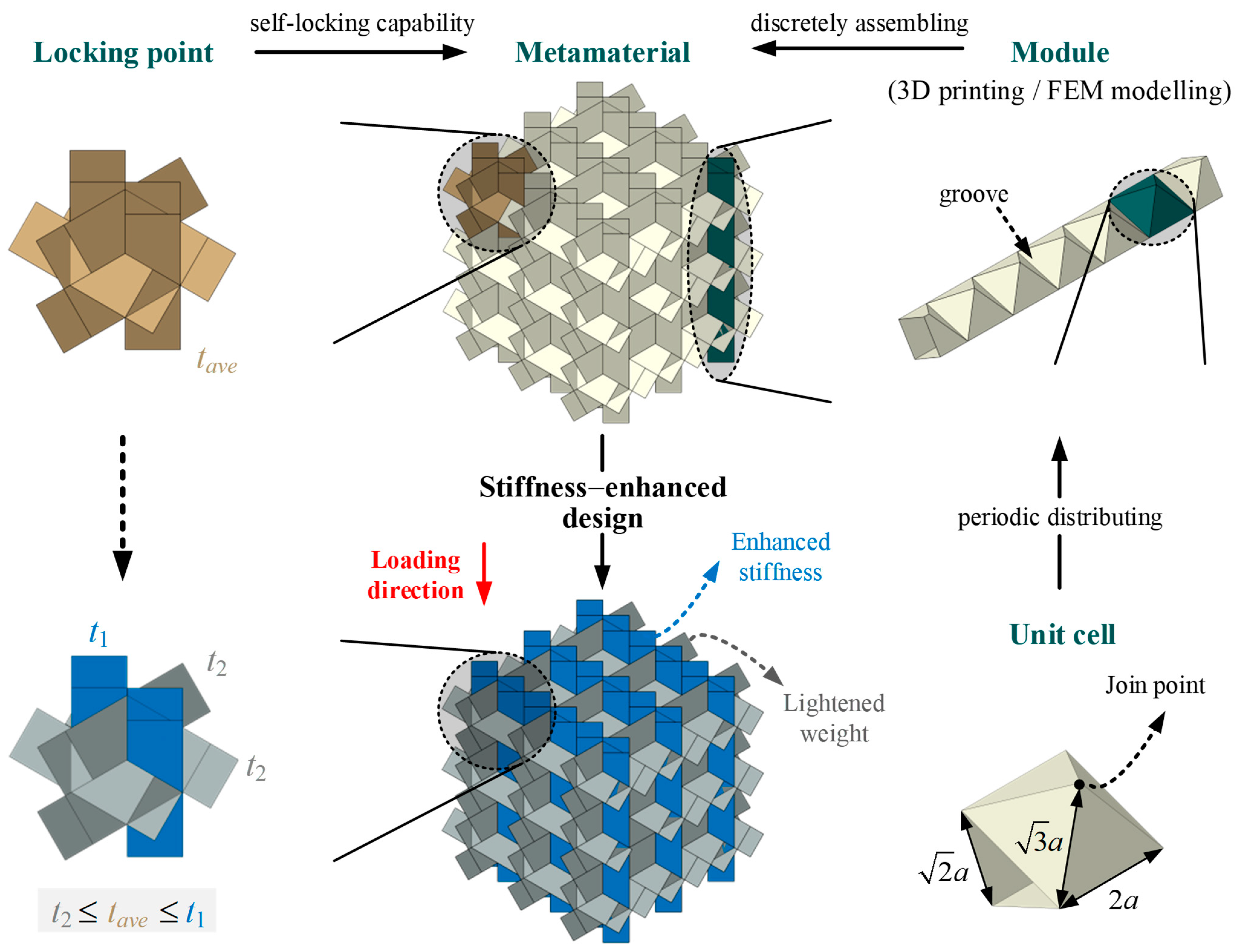
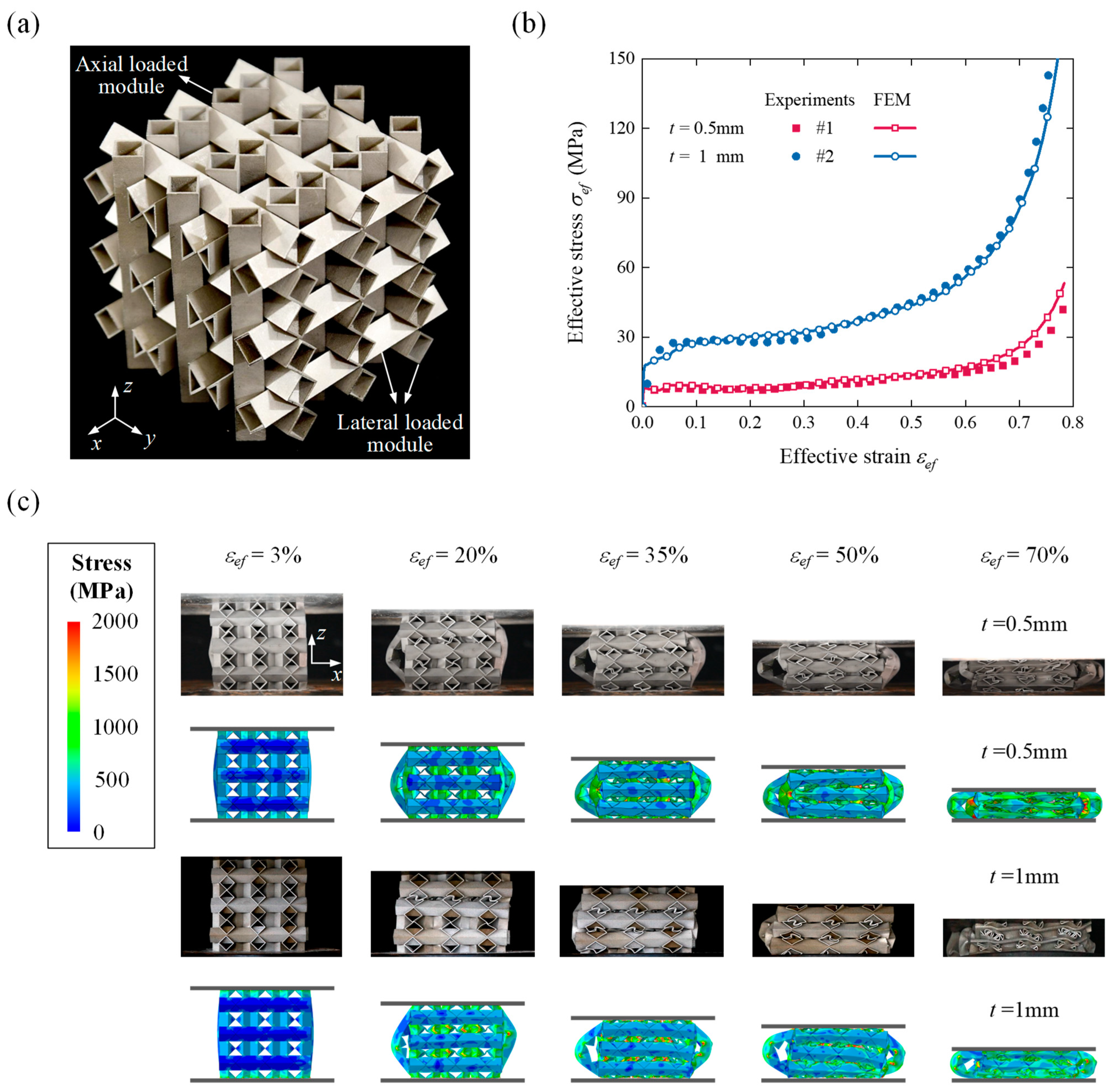
3.1. Modular Metamaterials
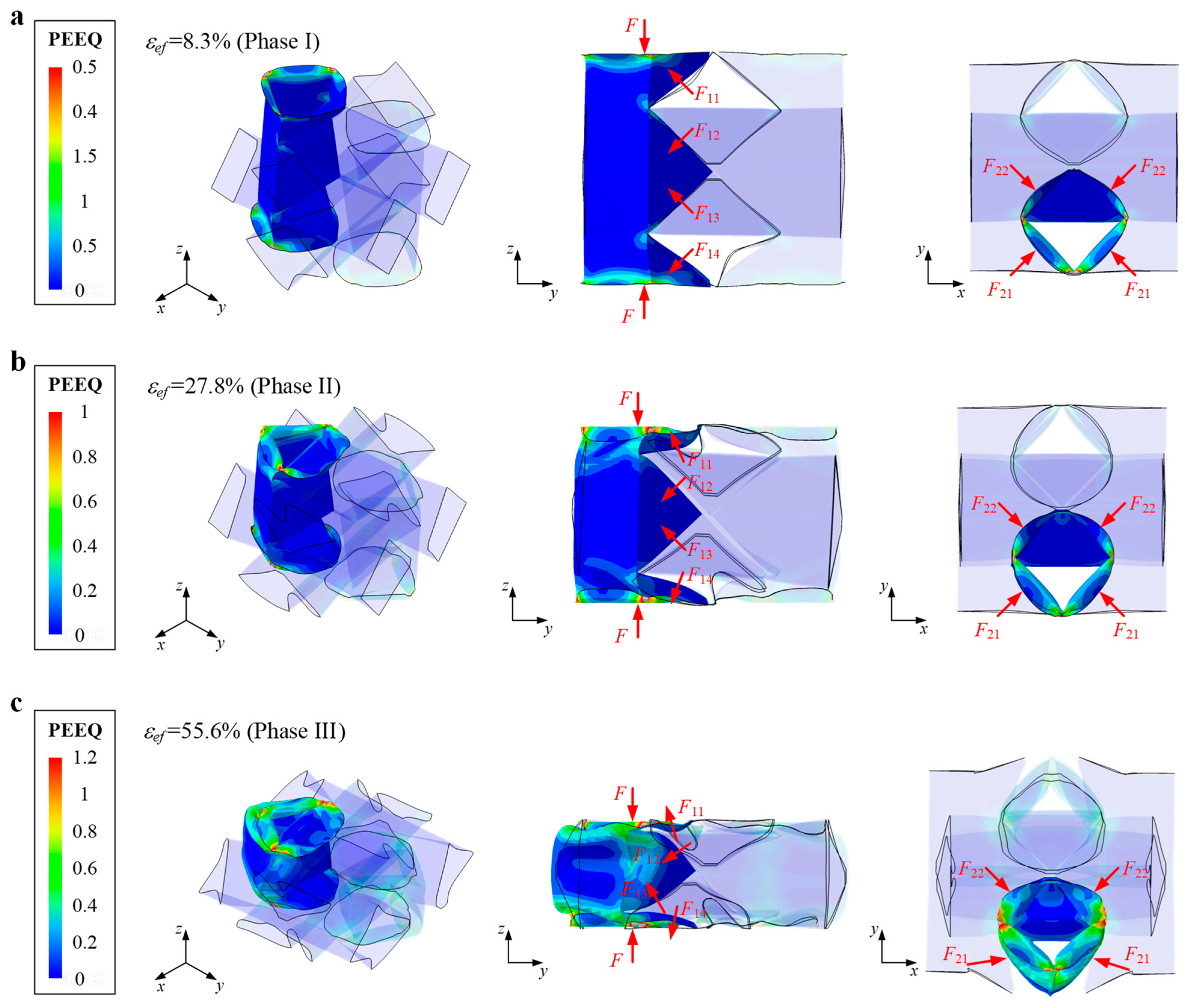
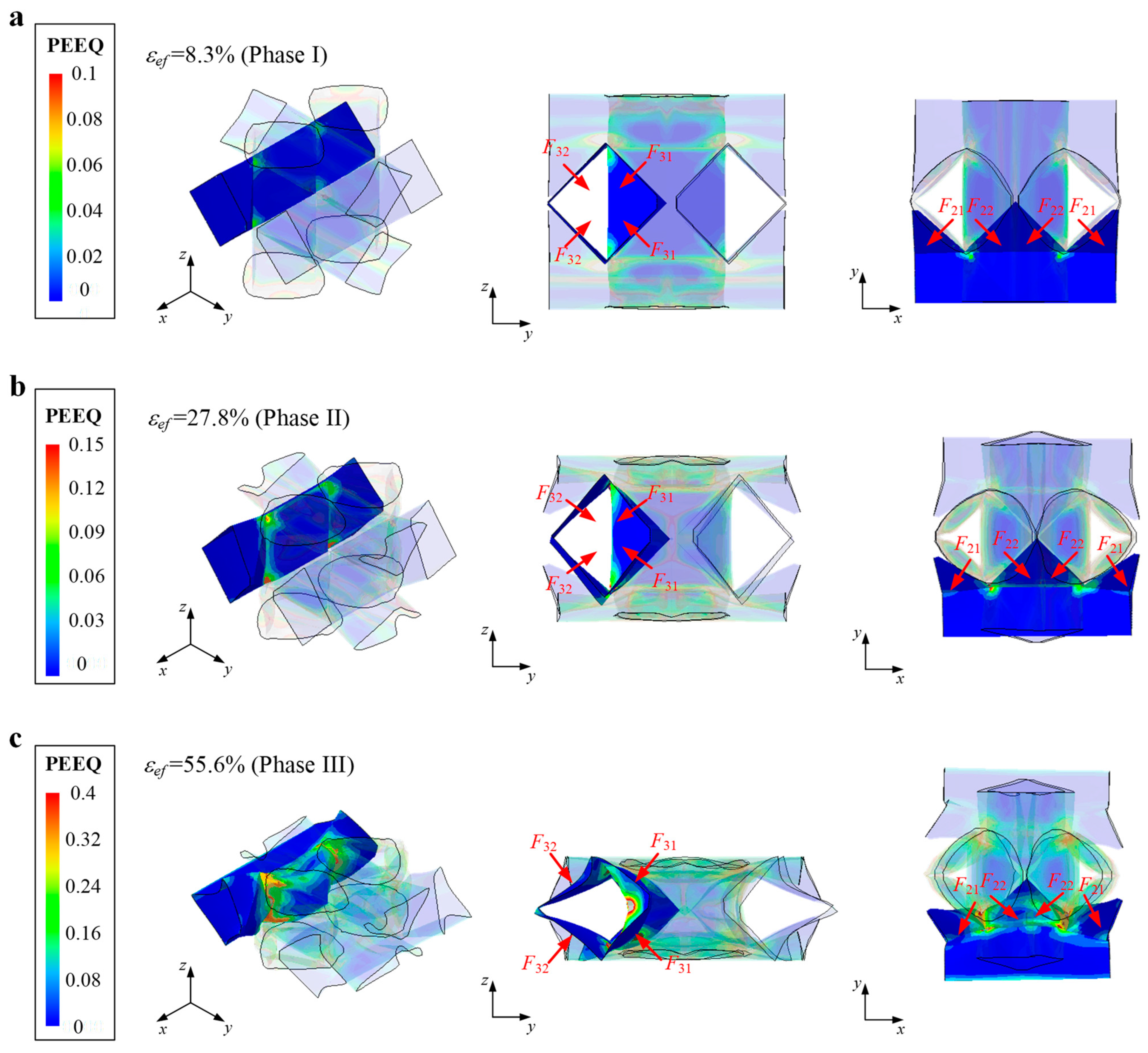
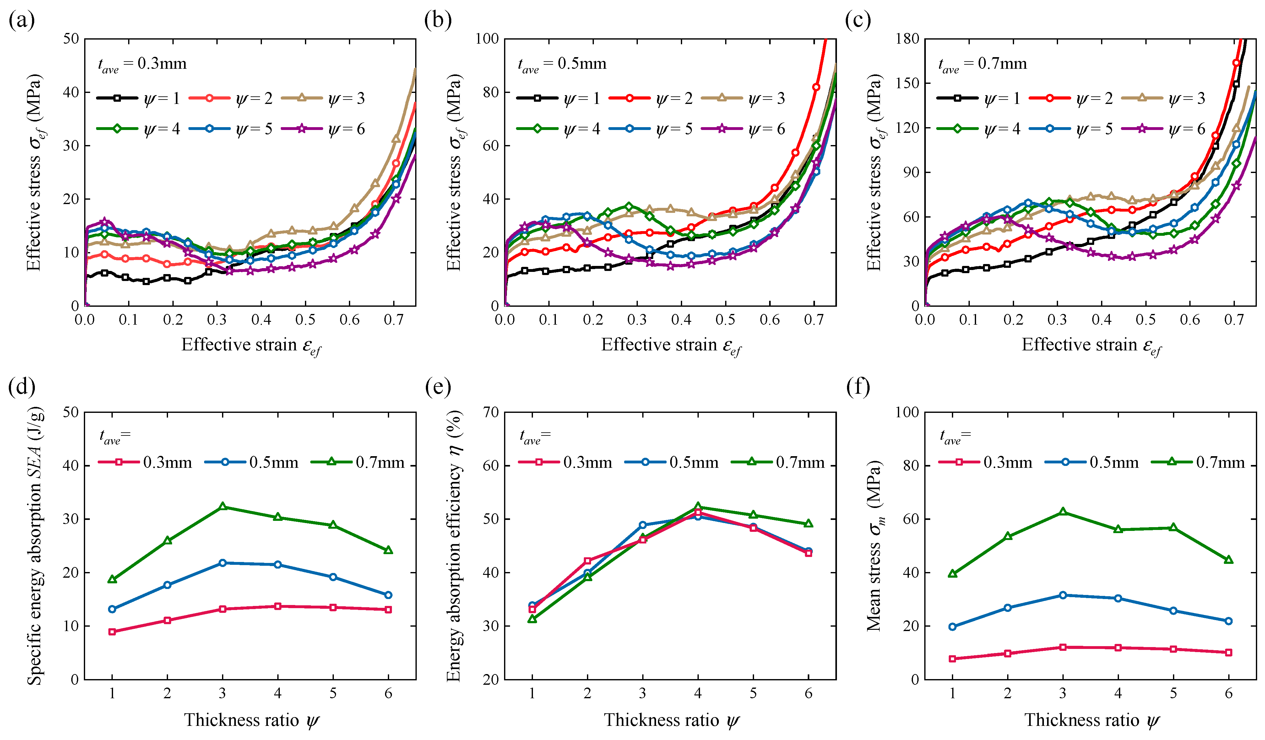
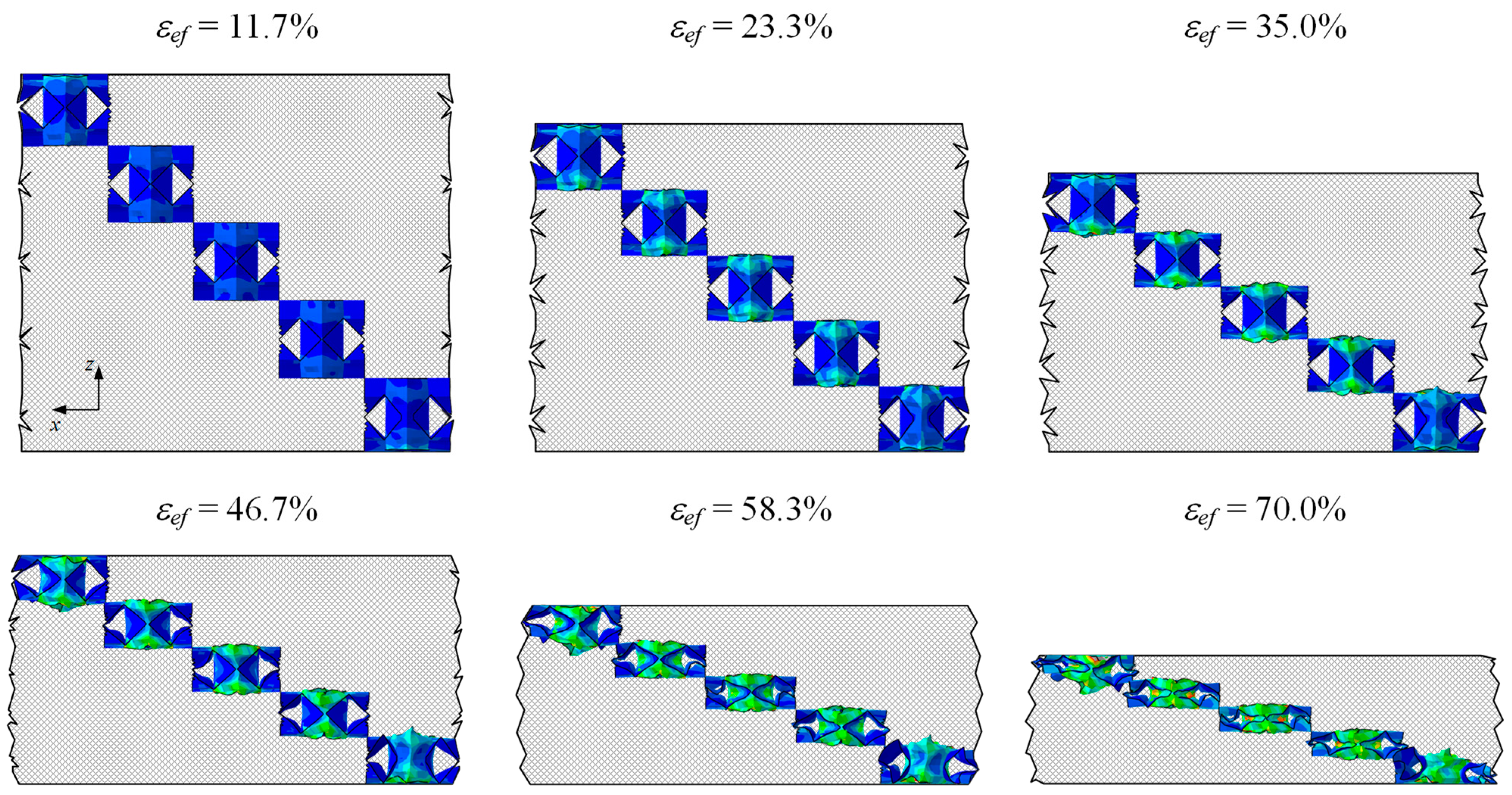
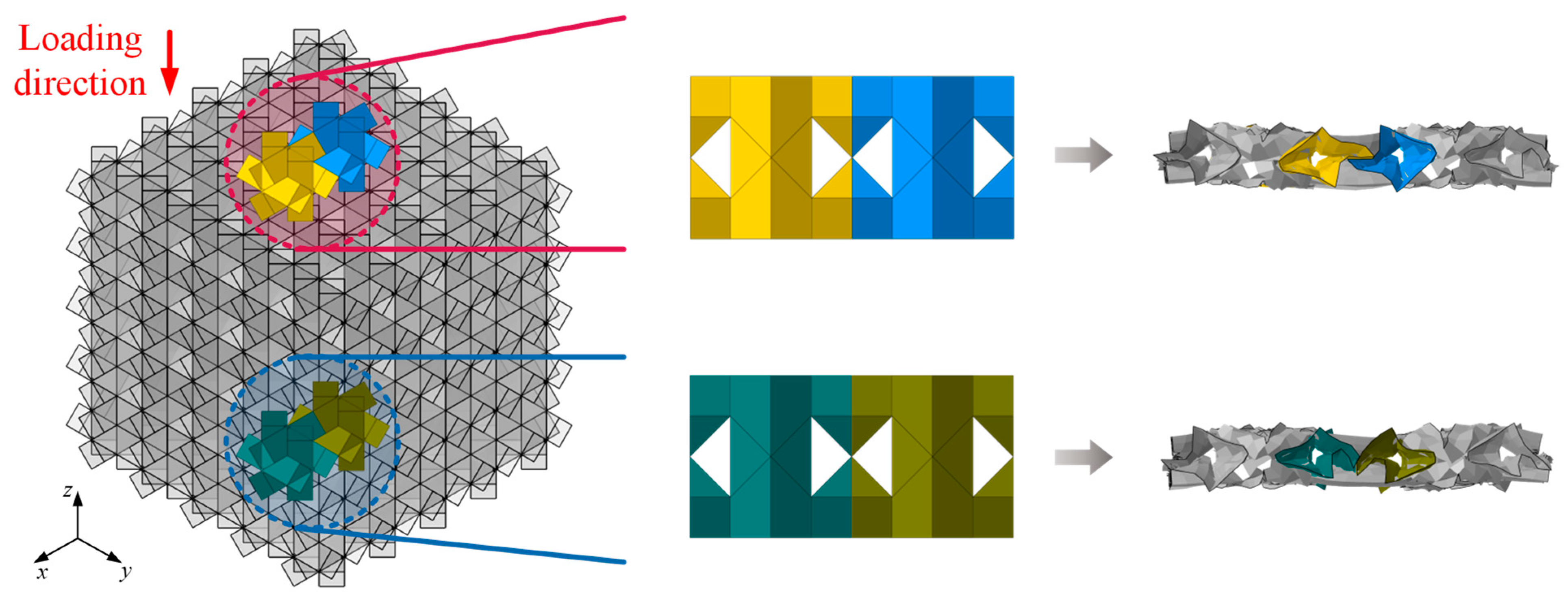
Quasi-static experiments are applied on the assembled metamaterial specimens to validate the FEM accuracy, with the assembled specimen (t = 1 mm) displayed in Figure 4a as an instance. The FEM stress–strain curves and deformed configurations of the metamaterials are consistent with the experiments (Figure 4b,c), and thus the FEM model is accurate enough to be used in the following analysis. From the results, the modules deform uniformly and stably when y = 1, and the effective stroke ratio is desirable as expected. The axial loaded modules produce more apparent plastic deformation in the complete process, which means that utilizing tougher axially loaded modules by suitably increasing y may enhance the crashworthiness. On another level, severe bending deformation of several axially loaded modules is observed after 20% effective strain, affecting the deforming stability and energy absorption capacity under a large deforming scale. This phenomenon may intensify when increasing y without changing the mean stress because the stiffness difference between axial and lateral loaded modules is enlarged. Thus, it is necessary to reveal the concrete effects of y on the energy absorption properties of the metamaterials under various mean thicknesses.
The FEM models of the metamaterials with 0.3   mm t a v e 0.7   mm and 1 ψ 6 are established to resist quasi-static loads, with the results of effective stress–strain curves and key performance indicators respectively depicted in Figure 5a–f. The value and smoothness of the metamaterial stress both increase with y when ψ 3 , while a clear negative stiffness phase appears when ψ 4 . This is because axial loaded modules tend to buckle severely under large y, which means the load capacity may instead decrease when increasing y. Therefore, the specific energy absorption SEA and mean stress sm increase with y when ψ 3 but decrease when ψ 4 (Figure 5d,f). The energy absorption efficiency h reaches a high level when 3 ψ 5 under various thicknesses because the maximal stress is slightly restricted by the negative stiffness behavior. In summary, increasing the thickness t can significantly enhance SEA and sm, while its effect on h can almost be ignored. ψ = 3 can be taken as the optimal design of metamaterials, which can increase SEA, h and sm, respectively, by 62.4%, 44.2% and 57.6% compared to the regular design ( ψ = 1 ).
Considering its design and application in actual engineering, it is necessary to develop a method to easily estimate the mean stress of the modular metamaterials. However, it has been observed from experimental and FEM deformations that the interaction effects among various modules are comparatively complex to quantitatively calculate membrane and bending energies. On the other hand, the bending tendencies of axial loaded modules are enhanced when increasing y, which means that the influence of the enhanced-stiffness degree on the deforming mode should be considered. Despite this, we discovered that the deforming details of various locking points in the same metamaterial are similar apart from the outside modules as shown in Figure 6. Therefore, we attempted to estimate the metamaterial stress by carrying out a mechanical analysis of locking points.

3.2. Locking Points

The FEM model of a locking point (n = 2) with t a v e = 0.5   mm and ψ = 1 is established to obtain its effective stress σ e f ,   l , as depicted as the black dashed line in Figure 7a. In comparison, the FEM models of the metamaterials with t a v e = 0.5   mm , ψ = 1 and 6 n 14 are established to obtain their effective stress σ e f ,   m , which is not obviously affected by n and depicted as dotted solid lines in Figure 7a. The deformation of each axial loaded module is restricted by 2n lateral loaded modules as shown in Figure 4, and thus the interaction effects among the modules are enhanced when elongating the modules by increasing n. This is why the metamaterial stress σ e f ,   m is significantly higher than the locking point stress σ e f ,   l , while their curve characteristics are similar. Herein, an enhancing coefficient l is introduced to describe the interaction effects of the modules in metamaterials, and it can be observed that the stress curves of σ e f ,   m and λ σ e f ,   l (black solid line in Figure 7a) are almost overlapped. Therefore, it is reasonable to estimate the mechanical behavior of the metamaterials after studying the properties of the locking points and the interaction effects among them.
The effective stress–strain curves and deformed configurations of the locking points under various tave and y1 are respectively provided in Figure 7b and Figure 8, which are obtained from quasi-static experiments and FEM simulations with details given in Section 2. The experimental and FEM results are highly consistent, verifying again the accuracy of the FEM model. As shown in Figure 7b, the locking point with t a v e = 0.5   mm and ψ = 1 displays desirable energy-absorbing properties due to its long effective stroke ratio and high stability. When the thickness is changed to t a v e = 1   mm to decrease the porosity, the mean stress is significantly enhanced while the effective stroke ratio is shortened. When the stiffness-enhanced design is implemented (y = 4), the mean stress is further enhanced and the effective stroke ratio is increasingly shortened because the stiffness of the locking point along the load direction is enhanced by increasing y. As shown in Figure 8, the locking points display a stable and efficient deforming mode under various tave and y. The modules are bound firmly, and axial loaded modules exhibit more obvious plastic deformation. In particular, the interaction effects among the modules are impaired when we clearly increase y1 as depicted as red circles in Figure 8, which means selecting further larger y1 may not be beneficial to improving the crashworthiness.
The FEM models of the locking points with 0.3   mm t a v e 0.7   mm and 1 ψ 6 are established to resist quasi-static loads, with the results of effective stress–strain curves and key performance indicators respectively depicted in Figure 9a–f. Similar to the metamaterial models, the value and smoothness of the locking point stress both increase with y when ψ 3 , while a slight negative stiffness phase appears when ψ 4 . In addition, the effective stroke ratio clearly decreases with y when ψ 3 . As shown in Figure 9d,f, the specific energy absorption SEA and mean stress sm increase with y, while the growth rate slows down significantly when ψ 4 . The energy absorption efficiency h is larger than the regular design when 2 ψ 3 under various thicknesses, and the contribution of increasing y on h is commonly impaired when ψ 3 . In summary, increasing the wall thickness t can significantly enhance SEA and sm, while its effect on h is not obvious. Considering both the deforming stability and energy-absorbing properties, ψ = 3 can also be considered as the optimal design of locking points, which can increase SEA, h and sm, respectively, by 28.7%, 21.5% and 37.4% compared to the regular design ( ψ = 1 ).

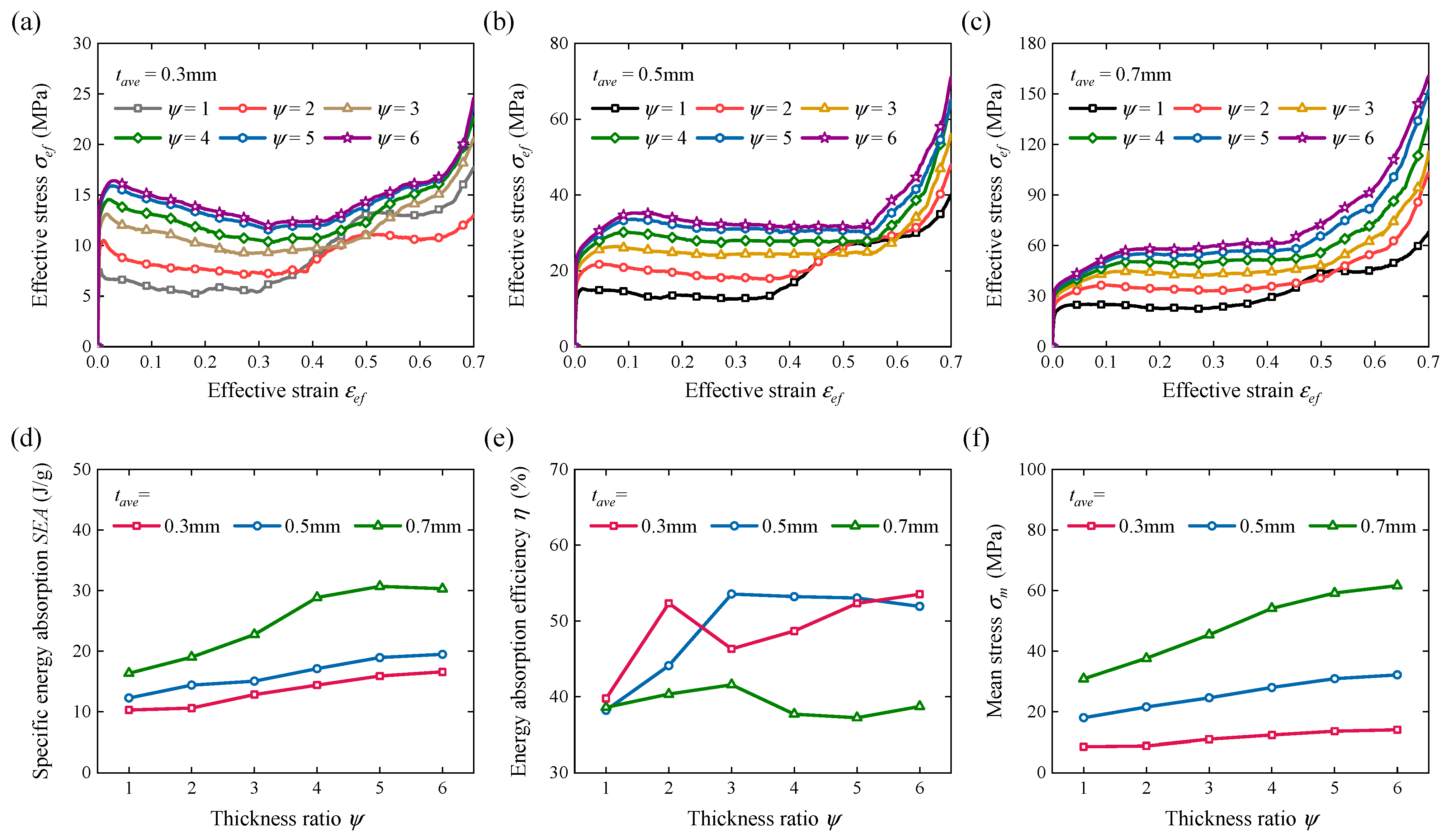
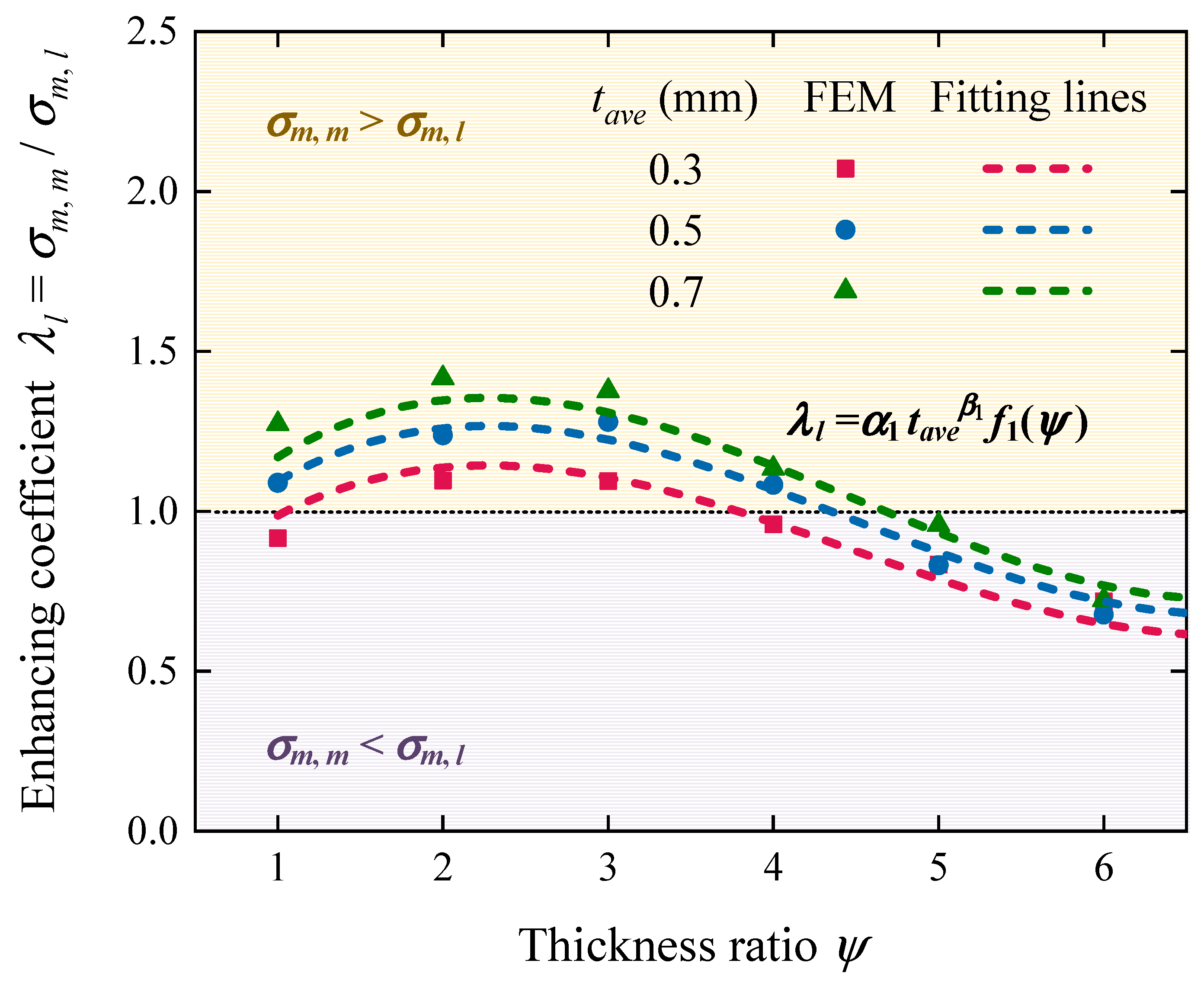
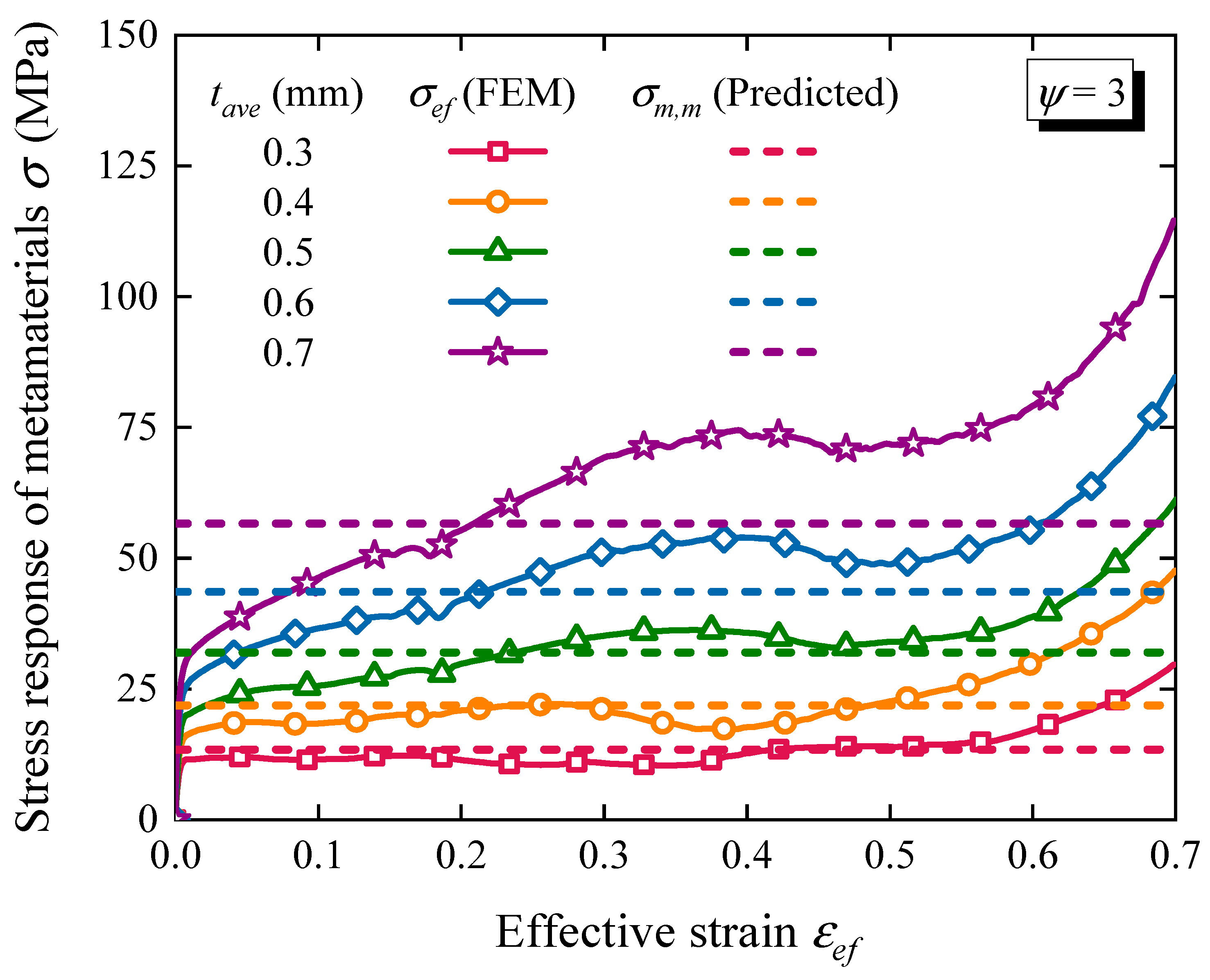
3.3. Estimation of Mean Stress

To reveal the relationship between the mean stress of the metamaterials and that of the locking points, σ m ,   m and σ m ,   l , an enhancing coefficient is defined as follows:
λ   l = σ m ,   m / σ m ,   l
which apparently increases with the interaction effects among the locking points in the metamaterials. The interaction effects contribute to enhancing crashworthiness when λ   l > 1 , and the interaction effects instead impact the crashworthiness when λ   l < 1 , which are respectively marked as light yellow and purple regions in Figure 10. The values of λ   l obtained from FEM simulation under 0.3   mm t a v e 0.7   mm and 1 ψ 6 are calculated based on the results in Figure 5f and Figure 9f, which are depicted as solid dots in Figure 10.
The enhancing coefficient λ   l increases with tave due to a larger equivalent density as shown in Figure 10, while this effect is clearly weakening under a larger y, because selecting a larger thickness will further aggravate the harmful global buckling mode. λ   l increases with y when ψ 3 and quickly decreases when ψ 3 , which is consistent with the mechanical analysis of Section 3.1 and Section 3.2. To effectively estimate the enhancing coefficient λ   l , a numerical method is introduced to fit the data points by the following expression:
λ l = α 1   t a v e β 1 f 1 ψ
where α 1 and β 1 are arbitrary constants, and f 1 is selected as a polynomial function of third order based on data characteristics in Figure 10, which can be expressed as
f 1 ψ = a 0 + a 1 ψ + a 2 ψ 3 + a 3 ψ 3
where a i   0 i 3 are arbitrary constants. The fitted curves of λ   l are displayed as dashed lines in Figure 10, with fitting numbers provided in Table 4. The actual and predicted values coincide well with each other, proving the reliability of the numerical fitting method to estimate the enhancing coefficient. It is apparent that the interaction effects among the locking points in metamaterials are mainly dominated by the thickness ratio y1 and slightly vary with the average thickness tave.
The values of σ m ,   l obtained from FEM simulation under 0.3   mm t a v e 0.7   mm and 1 ψ 6 are calculated based on results in Figure 9f, which are depicted as solid dots in Figure 11. σ m ,   l significantly increases with the thickness as expected, and their variations concerning y display the characteristics of power functions. The deformation energies of each module in single locking points are difficult to quantify, which derives from two factors: (1) complex interaction effects exist among the modules, and thus the contact forms between adjacent modules in different locking points are almost completely unpredictable (Figure 12); (2) each module is subjected to multiple loads from various adjacent modules, and thus the location and number of the plastic hinges cannot be accurately assumed (Appendix A). Thus, we also attempt to estimate the force response of the locking points by the numerical fitting method, and the fitting function of σ m ,   l is selected as follows according to data characteristics in Figure 11
σ m ,   l = α 2   t a v e β 2   ψ γ 2
where α 2 , β 2 and γ 2 are arbitrary constants. If we assume the effective average length of the folding lines in all modules as h, the total bending and membrane energies of the locking point, Eb and Em, satisfy that E b t 2 and E m t h 2 [46,47]. The compressive displacement is proportional to h, and thus the mean stress σ m ,   l satisfy that
σ m ,   l c 1 t 2 h + c 2 t h
where c 1 and c 2 are arbitrary constants. Based on the minimum energy principle, this satisfies that
σ m ,   l h = 0
from which we obtain that h t . The expression (12) can then be transformed into σ m ,   l t 3 2 . Therefore, β 2 = 1.5 is assumed in this work. α 2 and γ 2 are numerically fitted with the results in Table 4, and the fitted curve results are displayed as dashed lines in Figure 11.
The actual and predicted values of σ m ,   l coincide well with each other when t a v e 0.5   mm , while relative errors exist when t a v e = 0.7   mm . This is because the assumptions relying on thin-walled characteristics are no longer applicable, and the rationality of β 2 = 1.5 is affected. It is apparent that the interaction effects among the locking points in metamaterials are mainly dominated by the thickness ratio y1 and slightly vary with the average thickness tave. According to the values of β 1 and β 2 in Equations (9) and (11), the effect of thickness on the crashworthiness mainly derives from the term σ m , l rather than λ l .
The mean stress of the metamaterials σ m ,   m can thus be expressed as
σ m ,   m = α   t a v e β f ψ
where α = α 1 α 2 , β = β 1 + β 2 and f ψ = f 1 ψ ψ γ 2 . To verify its accuracy, the predicted values of the mean stress of metamaterials σ m ,   m are compared with their effective stress–strain curves obtained from FEM simulation as shown in Figure 13. Herein, the average thickness is selected as 0.3   mm t a v e 0.7   mm , and the optimal thickness ratio of ψ = 3 is selected based on the results of Section 3.1 and Section 3.2. From the results, the selected fitting parameters in Table 4 and β 2 = 1.5 are reliable for estimating the metamaterial crashworthiness by Equation (14). The actual values of σ m ,   m are calculated using stress curves and compared with the predicted values in Table 5, where the relative errors are no more than 9.6% under various thicknesses.
Based on the above results, a guideline for the design and application of modular metamaterials in engineering fields can be summarized:
(1)
Select ψ o p t = 3.25 as the optimal thickness ratio, which is obtained by substituting Equation (14) into σ m ,   m / ψ = 0 .
(2)
Select the module length and number based on actual storage space.
(3)
Select the average thickness tave according to the load characteristics. Increasing tave can significantly enhance the mean stress σ m ,   m and specific energy absorption SEA, and decreasing tave can lighten the weight and suitably elongate the effective stroke.

4. Conclusions

In this paper, we carried out experiments and FEM simulations to explore the optimal design and estimate the mean stress of burr puzzle-inspired modular metamaterials, which have been proposed recently to combine flexible, efficient, and adaptive impact resistance for enhancing sustainability in engineering protection. The modular metamaterials are discretely assembled by thin-walled modules without constraints, and each module is periodically distributed by unit cells. The module specimens manufactured by a 3D printing method using 316L stainless steel are employed to assemble metamaterials for quasi-static experiments, and the FEM simulation is carried out by ABAQUS/Explicit. The deformation of the metamaterials and the locking points is proven to be stable and uniform, and strong interaction effects are observed. The structural stiffness significantly increases with the average thickness tave and thickness ratio y. However, the deformation mode is gradually transformed into an inefficient global buckling mode and impairs the crashworthiness when ψ 4 . ψ = 3 can be taken as the optimal design of metamaterials, which can increase SEA, h and sm, respectively, by 62.4%, 44.2% and 57.6% compared to the regular design ( ψ = 1 ). Similarly, ψ = 3 can also be considered as the optimal design of the locking points, which can increase SEA, h, and sm, respectively, by 28.7%, 21.5% and 37.4% compared to the regular design. The mean stress of the metamaterials σ m ,   m is effectively estimated by a numerical fitting method, with a relative error less than 9.6%, and a guideline for their design and application in engineering fields is summarized. The optimal thickness ratio of ψ o p t = 3.25 has been derived, which coincides well with the experimental and FEM results. This work has remedied some weaknesses in previous work about modular metamaterials, and may open new avenues for estimating the mechanical behavior of complex engineering structures.

Author Contributions

Conceptualization, K.Y.; Software, K.Y. and X.L.; Validation, Y.Y.; Investigation, K.Y., X.L., Z.L. and W.Z.; Writing—original draft, K.Y.; Writing—review & editing, K.Y., W.Z. and Y.Y.; Supervision, Z.L. All authors have read and agreed to the published version of the manuscript.

Funding

This research was funded by the National Natural Science Foundation of China (Grant No. 12102490), the State Key Laboratory of Precision Blasting and the Hubei Key Laboratory of Blasting Engineering of Jianghan University (Grant No. PBSKL-2022-D-04).

Data Availability Statement

Data will be made available on request.

Acknowledgments

Support from the National Natural Science Foundation of China (Grant No. 12102490), the State Key Laboratory of Precision Blasting and the Hubei Key Laboratory of Blasting Engineering of Jianghan University (Grant No. PBSKL-2022-D-04) is gratefully acknowledged.

Conflicts of Interest

The authors declare no conflict of interest.

Appendix A. The Bearing and Deforming Diagrams of Various Modules in a Single Locking Point

The bearing and deforming diagrams of various modules in a single locking point with t a v e = 0.5   mm and ψ = 1 are extracted from FEM simulation, as shown in Figure A1, Figure A2 and Figure A3. Due to strong interaction effects, each module is squeezed by at least five adjacent modules. However, it can be observed that the deformation mode of each module is not symmetrical as expected, and the location and number of plastic hinges cannot be accurately assumed. Thus, quantitative mechanical analysis is difficult to carry out due to the complex load-bearing mechanism, and thus the mean stress of the locking point is estimated by the fitting method in Section 3.3.
Figure A1. The bearing and deforming diagrams of z-directional modules in a single locking point: (a) phase I, (b) phase II and (c) phase III.
Sustainability 15 13963 g0a1
Figure A2. The bearing and deforming diagrams of y-directional modules in a single locking point: (a) phase I, (b) phase II and (c) phase III.
Sustainability 15 13963 g0a2
Figure A3. The bearing and deforming diagrams of x-directional modules in a single locking point: (a) phase I, (b) phase II and (c) phase III.
Sustainability 15 13963 g0a3

References

  1. Lu, G.; Yu, T. Energy Absorption of Structures and Materials; Woodhead Publishing Ltd.: Cambridge, UK, 2003. [Google Scholar]
  2. Alghamdi, A. Collapsible impact energy absorbers: An overview. Thin-Walled Struct. 2001, 39, 189–213. [Google Scholar] [CrossRef]
  3. Abramowicz, W. Thin-walled structures as impact energy absorbers. Thin-Walled Struct. 2003, 41, 91–107. [Google Scholar] [CrossRef]
  4. Compton, B.G.; Lewis, J.A. 3D-printing of lightweight cellular composites. Adv. Mater. 2014, 26, 5930–5935. [Google Scholar] [CrossRef] [PubMed]
  5. Gibson, L.J.; Ashby, M.F. Cellular Solids: Structure and Properties; Cambridge University Press: Cambridge, UK, 1997. [Google Scholar]
  6. Yang, K.; Sun, Y.; Yao, Y.; Zhu, W. A universal strategy for flexible, efficient and programmable crashworthiness under quasi-static and dynamic loadings based on plastic deformation of metals. Mater. Des. 2022, 222, 111027. [Google Scholar] [CrossRef]
  7. Khan, S.Z.; Masood, S.H.; Ibrahim, E.; Ahmad, Z. Compressive behaviour of Neovius Triply Periodic Minimal Surface cellular structure manufactured by fused deposition modelling. Virtual Phys. Prototyp. 2019, 14, 360–370. [Google Scholar] [CrossRef]
  8. Wierzbicki, T. Crushing analysis of metal honeycombs. Int. J. Impact Eng. 1983, 1, 157–174. [Google Scholar] [CrossRef]
  9. Hu, L.; He, X.; Wu, G.; Yu, T. Dynamic crushing of the circular-celled honeycombs under out-of-plane impact. Int. J. Impact Eng. 2015, 75, 150–161. [Google Scholar] [CrossRef]
  10. Yang, K.; Li, Z.; Ge, D. Quasi-static and dynamic out-of-plane crashworthiness of 3D curved-walled mixed-phase honeycombs. Thin-Walled Struct. 2023, 182, 110305. [Google Scholar] [CrossRef]
  11. Qi, J.; Li, C.; Tie, Y.; Zheng, Y.; Duan, Y. Energy absorption characteristics of origami-inspired honeycomb sandwich structures under low-velocity impact loading. Mater. Des. 2021, 207, 109837. [Google Scholar] [CrossRef]
  12. Zhang, W.; Yin, S.; Yu, T.; Xu, J. Crushing resistance and energy absorption of pomelo peel inspired hierarchical honeycomb. Int. J. Impact Eng. 2019, 125, 163–172. [Google Scholar] [CrossRef]
  13. Ruan, D.; Lu, G.; Wang, B.; Yu, T.X. In-plane dynamic crushing of honeycombs—A finite element study. Int. J. Impact Eng. 2003, 28, 161–182. [Google Scholar] [CrossRef]
  14. Qi, C.; Jiang, F.; Yang, S. Advanced honeycomb designs for improving mechanical properties: A review. Compos. Part B Eng. 2021, 227, 109393. [Google Scholar] [CrossRef]
  15. Harris, J.A.; McShane, G.J. Metallic stacked origami cellular materials: Additive manufacturing, properties, and modelling. Int. J. Solids Struct. 2020, 185–186, 448–466. [Google Scholar] [CrossRef]
  16. Niknejad, A.; Abedi, M.M.; Liaghat, G.H.; Nejad, M.Z. Prediction of the mean folding force during the axial compression in foam-filled grooved tubes by theoretical analysis. Mater. Des. 2012, 37, 144–151. [Google Scholar] [CrossRef]
  17. Zhai, J.; Zhang, D.; Li, M.; Cui, C.; Cai, J. Out-of-plane energy absorption and crush behavior of origami honeycomb. Thin-Walled Struct. 2022, 181, 109966. [Google Scholar] [CrossRef]
  18. Hu, D.; Wang, Y.; Song, B.; Dang, L.; Zhang, Z. Energy-absorption characteristics of a bionic honeycomb tubular nested structure inspired by bamboo under axial crushing. Compos. Part B Eng. 2019, 162, 21–32. [Google Scholar] [CrossRef]
  19. Yang, C.; Kyriakides, S. Crushing of low density foams under triaxial loadings. Extrem. Mech. Lett. 2020, 35, 100620. [Google Scholar] [CrossRef]
  20. Wang, H.; Zhu, D.; Hou, S.; Yang, D.; Nieh, T.G.; Lu, Z. Cellular structure and energy absorption of AlCu alloy foams fabricated via a two-step foaming method. Mater. Des. 2020, 196, 109090. [Google Scholar] [CrossRef]
  21. Kaczyński, P.; Ptak, M.; Gawdzińska, K. Energy absorption of cast metal and composite foams tested in extremely low and high-temperatures. Mater. Des. 2020, 196, 109114. [Google Scholar] [CrossRef]
  22. Xue, R.; Cui, X.; Zhang, P.; Liu, K.; Li, Y.; Wu, W.; Liao, H. Mechanical design and energy absorption performances of novel dual scale hybrid plate-lattice mechanical metamaterials. Extrem. Mech. Lett. 2020, 40, 100918. [Google Scholar] [CrossRef]
  23. Wang, S.; Ma, Y.; Deng, Z. Stretching-dominated truss lattice materials: Elastic anisotropy evaluation, control, and design. Compos. Struct. 2022, 298, 116004. [Google Scholar] [CrossRef]
  24. Wang, Y.; Ramirez, B.; Carpenter, K.; Naify, C.; Hofmann, D.C.; Daraio, C. Architected lattices with adaptive energy absorption. Extrem. Mech. Lett. 2019, 33, 100557. [Google Scholar] [CrossRef]
  25. Mao, A.; Zhao, N.; Liang, Y.; Bai, H. Mechanically efficient cellular materials inspired by cuttlebone. Adv. Mater. 2021, 33, 2007348. [Google Scholar] [CrossRef] [PubMed]
  26. Jenett, B.; Cameron, C.; Tourlomousis, F.; Rubio, A.P.; Gershenfeld, N. Discretely assembled mechanical metamaterials. Sci. Adv. 2020, 6, eabc9943. [Google Scholar] [CrossRef] [PubMed]
  27. Cheng, X.; Zhang, Y.; Ren, X.; Han, D.; Jiang, W.; Zhang, X.G.; Luo, H.C.; Xie, Y.M. Design and mechanical characteristics of auxetic metamaterial with tunable stiffness. Int. J. Mech. Sci. 2022, 223, 107286. [Google Scholar] [CrossRef]
  28. Hu, J.; Tan, A.T.L.; Chen, H.; Hu, X. Superior compressive properties of 3D printed plate lattice mechanical metamaterials. Int. J. Mech. Sci. 2022, 231, 107586. [Google Scholar] [CrossRef]
  29. Tan, X.; Wang, B.; Yao, K.; Zhu, S.; Chen, S.; Xu, P.; Wang, L.; Sun, Y. Novel multi-stable mechanical metamaterials for trapping energy through shear deformation. Int. J. Mech. Sci. 2019, 164, 105168. [Google Scholar] [CrossRef]
  30. Khajeh-Khalili, F.; Honarvar, M.A.; Limiti, E. A Novel High-Isolation Resistor-Less Millimeter-Wave Power Divider Based on Metamaterial Structures for 5G Applications. IEEE Trans. Compon. Packag. Manuf. Technol. 2021, 11, 294–301. [Google Scholar] [CrossRef]
  31. Ben-Yelun, I.; Gómez-Carano, G.; Millán, F.J.S.; Sanz, M.Á.; Montáns, F.J.; Saucedo-Mora, L. GAM: General Auxetic Metamaterial with Tunable 3D Auxetic Behavior Using the Same Unit Cell Boundary Connectivity. Materials 2023, 16, 3473. [Google Scholar] [CrossRef]
  32. Khajeh-Khalili, F.; Honarvar, M.A.; Naser-Moghadasi, M.; Dolatshahi, M. High-gain, high-isolation, and wideband millimetre—Wave closely spaced multiple-input multiple-output antenna with metamaterial wall and metamaterial superstrate for 5G applications. IET Microw. Antennas Propag. 2021, 15, 379–388. [Google Scholar] [CrossRef]
  33. Gupta, A.; Sharma, R.; Thakur, A.; Gulia, P. Metamaterial foundation for seismic wave attenuation for low and wide frequency band. Sci. Rep. 2023, 13, 2293. [Google Scholar] [CrossRef] [PubMed]
  34. Lian, J.-W.; Ansari, M.; Hu, P.; Guo, Y.J.; Ding, D. Wideband and High-Efficiency Parallel-Plate Luneburg Lens Employing All-Metal Metamaterial for Multibeam Antenna Applications. IEEE Trans. Antennas Propag. 2023, 71, 3193–3203. [Google Scholar] [CrossRef]
  35. Pan, F.; Li, Y.; Li, Z.; Yang, J.; Liu, B.; Chen, Y. 3D pixel mechanical metamaterials. Adv. Mater. 2019, 31, 1900548. [Google Scholar] [CrossRef] [PubMed]
  36. Xin, X.; Liu, L.; Liu, Y.; Leng, J. 4D pixel mechanical metamaterials with programmable and reconfigurable properties. Adv. Funct. Mater. 2022, 32, 2107795. [Google Scholar] [CrossRef]
  37. Li, J.; Chen, Z.; Li, Q.; Jin, L.; Zhao, Z. Harnessing Friction in Intertwined Structures for High-Capacity Reusable Energy-Absorbing Architected Materials. Adv. Sci. 2022, 9, 2105769. [Google Scholar] [CrossRef]
  38. Fang, H.; Chu, S.A.; Xia, Y.; Wang, K.-W. Programmable self-locking origami mechanical metamaterials. Adv. Mater. 2018, 30, 1706311. [Google Scholar] [CrossRef]
  39. Kamrava, S.; Mousanezhad, D.; Ebrahimi, H.; Ghosh, R.; Vaziri, A. Origami-based cellular metamaterial with auxetic, bistable, and self-locking properties. Sci. Rep. 2017, 7, 46046. [Google Scholar] [CrossRef]
  40. Chen, Y.; Qiao, C.; Qiu, X.; Zhao, S.; Zhen, C.; Liu, B. A novel self-locked energy absorbing system. J. Mech. Phys. Solids 2016, 87, 130–149. [Google Scholar] [CrossRef]
  41. Chen, Z.; Wu, Q.; Yang, H.; Yang, L.; Xiong, J. A periodic dissipative system with self-locking capacity. Int. J. Impact Eng. 2022, 166, 104233. [Google Scholar] [CrossRef]
  42. Zhao, Y.; Chen, L.; Du, B.; Liu, H.; Chen, B.; Peng, S.; Guo, Y.; Chen, L.; Li, W.; Fang, D. Bidirectional self-locked energy absorbing system: Design and quasi-static compression properties. Thin-Walled Struct. 2019, 144, 106366. [Google Scholar] [CrossRef]
  43. Liu, Y.; Xiong, F.; Yang, K.; Chen, Y. A novel omnidirectional self-locked energy absorption system inspired by windmill. J. Appl. Mech. 2020, 87, 085001. [Google Scholar] [CrossRef]
  44. Yang, K.; Rao, L.; Hu, L.; Pan, F.; Yin, Q.; Chen, Y. Flexible, efficient and adaptive modular impact-resistant metamaterials. Int. J. Mech. Sci. 2022, 239, 107893. [Google Scholar] [CrossRef]
  45. Wang, H.; Yang, J.; Liu, H.; Sun, Y.; Yu, T. Internally nested circular tube system subjected to lateral impact loading. Thin-Walled Struct. 2015, 91, 72–81. [Google Scholar] [CrossRef]
  46. Ha, N.S.; Pham, T.M.; Tran, T.T.; Hao, H.; Lu, G. Mechanical properties and energy absorption of bio-inspired hierarchical circular honeycomb. Compos. Part B Eng. 2022, 236, 109818. [Google Scholar] [CrossRef]
  47. Zhang, X.; Zhang, H. Numerical and theoretical studies on energy absorption of three-panel angle elements. Int. J. Impact Eng. 2012, 46, 23–40. [Google Scholar] [CrossRef]
Figure 1. Schematic diagrams of regular and stiffness-enhanced modular metamaterials.
Sustainability 15 13963 g001
Figure 2. Experimental instruments: (a) iSLM280 metal 3D printer, (b) TIYINS-HCM206B test machine and (c) MTSE 45.305 test machine.
Sustainability 15 13963 g002
Figure 3. FEM simulation details: load conditions of (a) metamaterial and (b) locking point models, and (c) results of mesh convergence study.
Sustainability 15 13963 g003
Figure 4. Quasi-static experimental and simulation results of metamaterials with t = 0.5 mm and t = 1 mm: (a) the assembled specimen (t = 1 mm), (b) the force response and (c) the deformed configurations.
Sustainability 15 13963 g004
Figure 5. Crash performance of metamaterials under various tave and y: (ac) effective stress–strain curves, and (df) key performance indicators.
Sustainability 15 13963 g005
Figure 6. The deformation comparison of nonadjacent locking points in various layers.
Sustainability 15 13963 g006
Figure 7. The force responses of metamaterials and locking points: (a) comparison of locking point and metamaterials under various n, and (b) comparison of locking points under various tave and y.
Sustainability 15 13963 g007
Figure 8. Experimental and simulation deformation of locking points under various parameters: (a) t1 = 0.5 mm, t2 = 0.5 mm, (b) t1 = 1 mm, t2 = 1 mm, (c) t1 = 2 mm, t2 = 0.5 mm.
Sustainability 15 13963 g008
Figure 9. Crash performance of locking points under various tave and y: (ac) effective stress–strain curves, and (df) key performance indicators.
Sustainability 15 13963 g009
Figure 10. Enhancing coefficient ll to represent the interaction effects among locking points in metamaterials: actual values from FEM simulation and estimated values.
Sustainability 15 13963 g010
Figure 11. Mean stress of the locking points under various tave and ψ: actual values from FEM simulation and predicted values.
Sustainability 15 13963 g011
Figure 12. The deformation comparison of adjacent locking points in same layer.
Sustainability 15 13963 g012
Figure 13. The stress response of the metamaterials: actual stress–strain curves obtained from FEM simulation and predicted mean stress.
Sustainability 15 13963 g013
Table 1. Material properties of 316L stainless steel [10,44].
Young’s Modulus
E (GPa)
Poisson’s
Ratio
u
Yield
Stress
σs (MPa)
Hardening Modulus
Ep (MPa)
Ultimate Stress
σu (MPa)
Density
ρs (kg/m3)
2060.336011006647980
Table 2. Basic design parameters of metamaterial specimens (Section 3.1).
Metamaterial Specimentave
(mm)
t1
(mm)
t2
(mm)
ψa
(mm)
nmmeta
(kg)
Regular #10.50.50.51961.08
Regular #21111962.16
Table 3. Basic design parameters of locking point specimens (Section 3.2).
Locking Point Specimentave
(mm)
t1
(mm)
t2
(mm)
ψa
(mm)
nmlock
(g)
Regular #3 & #40.50.50.519243.84
Regular #5 & #611119287.68
Stiffness-enhanced #7 & #8120.549287.68
Table 4. Fitting parameters for estimating the mean stress of metamaterials and locking points.
λ   l = σ m ,   m / σ m ,   l = α 1   t a v e β 1 f 1 ψ σ m ,   l = α 2   t a v e β 2   ψ γ 2
α1β1a0a1a2a3α2γ2
1.150.20.6440.616−0.1820.01449.170.37
Table 5. Comparisons between actual and predicted values of σ m ,   m .
Average Thickness tave (mm)Mean Stress of Metamaterials σ m ,   m
Actual ValuePredicted ValueRelative Error
0.312.5913.416.11%
0.420.3421.97.12%
0.531.5531.951.25%
0.645.6243.564.52%
0.762.6156.619.58%
Disclaimer/Publisher’s Note: The statements, opinions and data contained in all publications are solely those of the individual author(s) and contributor(s) and not of MDPI and/or the editor(s). MDPI and/or the editor(s) disclaim responsibility for any injury to people or property resulting from any ideas, methods, instructions or products referred to in the content.

