1. Introduction
1.1. Motivations
Environmental issues caused by human activity have raised several concerns in modern society about how to achieve sustainable development. For this purpose, several countries have signed their commitment with initiatives such as the United Nations (UN) 2030 Agenda, where some sustainable development goals (SDGs) have been defined to decarbonize global economies [
1,
2]. In this scenario, different studies have pointed out electrification as a crucial step in achieving such goals [
3,
4], since electricity is an essential resource with strong relationships with most of the SDGs [
5].
For those reasons, different countries have implemented several policies for encouraging investments in non-conventional renewable energy sources (RES) like wind and solar energy [
6]. This has resulted in the exponential integration of RES into the conventional power system. However, such RES present an intermittent nature and lack of inertia, which challenges the suitable operation of the power system [
7,
8,
9,
10]. Such concerns have raised the necessity to integrate RES in a coordinated way, leading to the microgrid concept [
11].
The microgrid concept involves the coordinated management of multiple distributed energy resources (DERs), including distributed generation (DG), energy storage systems, smart loads, and advanced metering technologies among others to act as a single controllable entity with respect to the grid [
11]. The microgrid also must operate in islanded mode. However, in this operation mode, the microgrid becomes a small power system with a lower short circuit ratio (SCR) and is consequently more susceptible to power quality (PQ) disturbances such as those instigated by nonlinear loads (NLLs). This heightened vulnerability to PQ issues can have notable economic ramifications [
12,
13]. In this way, if these challenges remain unaddressed, then they could potentially dissuade the adoption of the microgrid concept, thereby impeding progress toward a more sustainable energy transition. Hence, it becomes evident that achieving decarbonization goals significantly depends on effectively mitigating these microgrid PQ challenges, which is essential for facilitating seamless and reliable grid integration of the DERs. Hence, it is essential to propose and study different strategies to manage PQ issues during a microgrid’s islanded operation [
14,
15].
1.2. Literature Review
For several years, studies related to microgrids have focused on power sharing, hierarchical control, and frequency and voltage control. However, PQ issues were ignored during this first stage of development. Then, voltage unbalances due to unbalance loads were addressed in [
16,
17,
18].
The harmonic disturbances introduced by NLLs have also been addressed in the literature. One of the available options addresses this problem by improving the harmonic current sharing among the microgrid power converters, usually among voltage-controlled converters (VCCs) [
19,
20,
21,
22,
23,
24,
25]. Despite this, the harmonic current sharing between VCCs and current-controlled converters (CCCs) was also reported in [
26,
27]. In all of those techniques, the harmonic current-sharing strategies can act to achieve different control objectives, such as lowering the voltage distortion at certain microgrid bus bars or sharing the current harmonics according to each converter’s nominal power to avoid overloading. However, such techniques usually lead to a higher voltage harmonic content, which can result in widespread harmonic disturbance along the microgrid.
Furthermore, the use of active power filters (APFs) and multifunctional converters has also been proposed in the literature to address harmonic disturbances in grid-connected microgrids [
28,
29,
30]. In the case of islanded AC microgrids involving VCCs, CCCs and NLLs, an evident lack of studies considering PQ issues is noted. Two notable exceptions in the literature are [
31,
32]. In [
31], an autonomous control strategy for harmonic current sharing between the VCC and CCC was developed based on the virtual impedance and admittance techniques. Furthermore, in [
32], the impact of a multifunctional converter on the microgrid’s small-signal stability was analyzed. However, a detailed analysis of the PQ’s improvement was not presented.
1.3. Objectives
According to the above discussions, it can be noticed that addressing microgrid PQ issues is essential for the large-scale adoption of microgrids and renewable energy sources, which is essential to accomplish decarbonization goals. However, it is possible to identify a lack of studies analyzing and assessing the PQ of an islanded AC microgrid regarding VCCs, multifunctional CCCs, and NLLs, where the harmonic disturbances are compensated locally to avoid widespread harmonic disturbances along the microgrid. Hence, in this paper, a comprehensive PQ assessment within an islanded AC microgrid is presented, taking into consideration the influence of NLLs, VCCs, and CCCs. The analysis encompasses two distinct scenarios:
The first scenario involves the CCC functioning as a conventional grid-feeding converter, with the active filtering function (AFF) disabled. This scenario closely resembles the integration of a traditional renewable DG system into an islanded microgrid, as the grid-feeding CCC corresponds to the current industry standard for grid integration of DG systems. In this way, as a first step of this research, it is assessed if, in the presence of an NLL, this configuration results in acceptable PQ indexes or if it is necessary to adopt more advanced techniques to operate with suitable PQ indexes.
In the second scenario, the multifunctional CCC’s AFF is enabled, allowing it to supply harmonic currents associated with the NLLs. This scenario is explored due to the effectiveness of implementing the AFF within a CCC to address power quality issues due to NLLs. However, it is important to highlight that the proposal of this paper consists of implementing the AFF with the minimal amount of modifications possible to the control strategy of the first scenario so it can be interpreted as an upgraded version of the existing renewable DG systems. Hence, the implemented AFF involves only the addition of the measurements of the local NLL currents and the inclusion of an algorithm to extract their harmonic components.
The study conducts an assessment of both the microgrid and converter control performance from a PQ perspective in both scenarios. Consequently, this research provides a comprehensive analysis of microgrid PQ grounded in experimental results.
2. Overview of Converter Control
In AC microgrid systems, there are two main power converters classifications, known as the grid-following converter and grid-forming converter [
33,
34]. Thus, in this section, the different microgrid converter control techniques used in this paper are explained in detail.
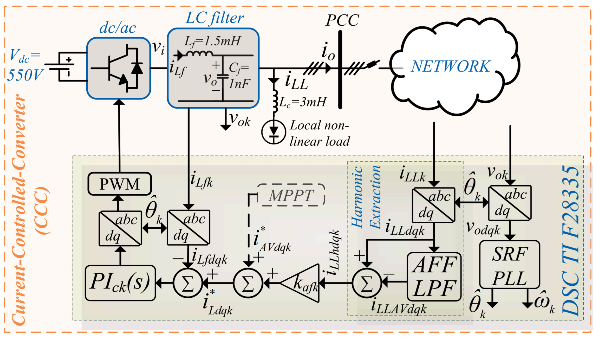
2.1. Multifunctional CCC Control
The multifunctional CCC technique is illustrated in
Figure 1. CCCs have been widely used in different applications of grid-tied power converters, such as active power filters [
35,
36], and for the grid integration of intermittent renewable energy sources, such as wind and solar energy [
37,
38,
39,
40,
41]. More recently, power converters able to perform both of the mentioned functions have been reported in the literature and have been called multifunctional converters [
28,
42,
43,
44]. However, it is important to highlight that the proposal of this paper consists of implementing the AFF with the minimal modifications possible to the traditional control strategy of conventional grid-feeding converters so it can be interpreted as an upgraded version of the existing renewable DG systems. Hence, the implemented AFF involves only the addition of the measurements of the local NLL currents and the inclusion of an algorithm to extract their harmonic components, as will be discussed in this section.
From the AC microgrid control perspective, such a type of converter control is known as grid-following converter control since it injects a current into the electric power system while “following” a preestablished voltage and frequency imposed either by the grid or by grid-forming converters [
33,
34].
As depicted in
Figure 1, the multifunctional CCC in this paper comprises a synchronous reference frame (SRF) phase-locked loop (PLL) [
45], which is encharged to estimate the instantaneous voltage phase (
) and its frequency (
). These variables are then used for the CCC control algorithms, especially for the DQ current and voltage transformations. For this purpose, the SRF PLL uses a proportional-integral (PI) controller as given by
where
is the voltage normalization gain,
represents the PLL’s proportional gain,
corresponds to the PLL’s integral gain, and
is the quadrature component of the multifunctional CCC output voltage.
The current reference (
) that must be injected by the CCC is computed as follows:
where
is the active current component that should be injected into the microgrid,
corresponds to a gain that allows partial harmonic compensation in order to manage the loading of the inverter [
43], and
represents the harmonic current components of the nonlinear local load estimated by the harmonic extraction algorithm, which is given by
where
is the cutoff frequency of the CCC’s harmonic extraction filter and
represents the DQ components of the local NLL current.
Finally, the reference current
is tracked by a conventional SRF PI current controller, and control action is then transformed into “abc” components to be used in the PWM modulator of a three-phase, three-leg inverter, as illustrated in
Figure 1. Then, an inductive (L) output filter is in charge of attenuating switching frequencies associated with the PWM. Also, there are three star-connected output capacitors to measure the local line-to-neutral voltages. For this reason, a small capacitance is used.
In this way, the adopted control structure enables the converter to perform both grid feeding and the AFF simultaneously. Furthermore, it is important to highlight that when , this means that the AFF is fully enabled, and thus the CCC operates as a multifunctional inverter, which should improve the microgrid PQ since the AFF avoids widespread NLL harmonic disturbances. Also, when , the AFF is disabled, and the CCC operates as a conventional grid-feeding converter.
2.2. Grid-Forming Converter Control
As described in the previous subsection, the grid-following inverters require a preestablished voltage and frequency. Hence, to enable the microgrid’s islanded operation, another control structure is necessary, known as grid-forming control [
33,
46,
47,
48].
The implementation of the grid-forming converter control considered in this paper is depicted in
Figure 2. Compared with the grid-following structure, it can be noticed that the grid-forming converter does not have a PLL since this converter does not need to extract the instantaneous voltage phase. This is because the grid-forming converter regulates its output voltage. Thus, this converter tends to operate as an ideal voltage source because it consists of a VCC, as
Figure 2 illustrates.
The voltage reference that the voltage controller should track is computed by the droop and virtual impedance control techniques. For this purpose, the average active and reactive power must be computed as follows:
where
is the measuring filter cutoff frequency,
and
correspond to the output voltages of the DQ components,
and
refer to the DQ components of the output currents, and
and
are the instantaneous active and reactive powers defined in the SRF, respectively.
Once the average active and reactive power are computed, the frequency and the output voltage reference are calculated in Equations (
5) and (
6), respectively, using the droop control to achieve power sharing among the converters [
49,
50] and the virtual impedance technique to enhance the converter and microgrid stability [
51,
52]:
where
and
are the voltage angular frequency and instantaneous phase references, respectively,
and
refer to the DQ components of the voltage reference,
and
correspond to the
and
droop coefficients, respectively,
and
are the virtual resistance and inductance, respectively, and
and
are the values of
and
V at no load, respectively.
The voltage references
are tracked by standard dual-loop SRF PI controllers as depicted in
Figure 2. The outer PI loop and the feedforward control gain (
) are in charge of computing the reference current that must circulate through the inductor (
) to keep the output voltage at the reference value. Finally, the inner controller is responsible for tracking the reference current. The control action of this controller is then transformed into “abc” components to be used in the PWM modulator of a three-phase, three-leg inverter, as illustrated in
Figure 2.
3. Experimental Set-Up
In this section, a detailed description of the experimental set-up is provided, and the key microgrid and control parameters are presented.
All the microgrid converters were based on Semikron IGBT SKM100GB12 modules and the SKHI 22A driver. For accurate monitoring and control of the voltage and current, LEM transducers were employed, specifically the LV 25P and LA 55p models, respectively. These transducers and the signal conditioning boards provided precise measurements for the digital signal controller (DSC). Moreover, the control functions and algorithms for the converters were executed on the DSC TI TMS320F28335, which performed 32 bit floating-point calculations.
Figure 3a,b illustrates the single-line diagram and a photograph of the three-phase experimental microgrid prototype featured in this paper, respectively. The microgrid consisted of three bus bars, with the VCCs connected to the first and third bus bars. The CCC was linked to the second bus bar, which also hosted an NLL consisting of a noncontrolled three-phase rectifier with a resistive load. Additionally, a resistive load was connected to the third bus bar, and the impedance of the microgrid distribution lines was incorporated through toroidal inductors.
The start-up process of the microgrid began with a voltage ramp of the VCC linked to the first bus bar, thereby energizing the microgrid. Subsequently, the synchronization process of the VCC at bus bar 3 started. This process ensured that both VCCs’ voltages maintained identical phases and sequences before their interconnection. Once synchronization was successfully achieved, a circuit breaker was turned on, facilitating the interconnection of both VCCs. Finally, the CCC was activated and integrated into the microgrid, allowing it to assume its designated role in the system’s operation according to its operation mode.
All the microgrid and converter parameters used in this paper are presented in
Table 1, and the main considerations for the design of the CCC and VCC controllers are detailed in [
32]. Finally, the experimental results, waveforms, and harmonic spectra were captured through a Yokogawa WT3000, as can be seen in
Figure 3a,b.
4. Experimental Results
This section presents selected experimental results to assess the microgrid PQ when the multifunctional CCC operated with the AFF disabled and with the AFF fully enabled. Hence, the PQ improvement provided by the multifunctional CCC AFF will be assessed.
The experimental results are presented as follows:
4.1. Discussion
4.1.1. Multifunctional CCC AFF Disabled
When the multifunctional CCC AFF is disabled, it operates as a conventional grid-feeding inverter. Hence, in this case, the CCC should inject a sinusoidal current. This behavior can be verified in
Figure 4e. As a consequence, the current harmonic components associated with the local NLL (see the last waveform in
Figure 4e) must be supplied by the VCCs. This can be constated by the results provided in
Figure 4c, where the output current delivered or demanded by the CCC plus the local NLL are displayed (see
in
Figure 3a). It can be observed that the VCCs were supplying distorted currents for the NLL. As a result, the harmonic disturbances introduced by the NLL caused the presence of the fifth and seventh harmonic voltage components at bus bar 2, as can be confirmed in
Figure 6c, which are the same predominant components present at the NLL current according to
Figure 5i. This led to a voltage total harmonic distortion (THD) of
, which is in agreement with
Figure 7c. It is important to observe that such voltage harmonic components constitute a disturbance for the CCC control loops, which explains why some harmonic current components were observed in the current injected by the CCC (
) in
Figure 5e.
Furthermore, it can be observed in
Figure 4a,g that the output currents of both VCCs presented high harmonic distortion, mainly due to the presence of the fifth and seventh harmonic components, as can be confirmed through the current harmonic spectra presented in
Figure 5a,g. This led to a current THD between
and
according to
Figure 7a,g. Also, it is interesting to observe that the current supplied by the VCC at bus bar 1 presented a higher harmonic content than that supplied by the VCC at bus bar 3. This occurred mainly due to two reasons. First, the droop control did not ensure harmonic current sharing, and second, the impedance between the VCC at bus bar 1 and the load was lower than the impedance between the VCC at bus bar 3 and the load. Several control techniques improve the harmonic current sharing among the microgrid power converters [
20,
21,
22,
23,
25]. However, such techniques usually lead to a higher voltage harmonic content, which can result in widespread harmonic disturbance along the microgrid. For this reason, the research focus in this paper was devoted to exploring the advantages of locally solving harmonic disturbances using the multifunctional CCC AFF.
Since the VCCs were controlled to provide sinusoidal and balanced three-phase voltages, their output currents were a consequence of the connected load. Hence, it is important to notice that although some voltage harmonics can be observed in
Figure 6a,e, the VCCs’ voltage THD remained below
, which demonstrates the effectiveness of the designed voltage controller since this corresponds with the expected behavior of an AC voltage source (i.e., the voltage waveform remains sinusoidal even when the output currents present harmonic disturbances).
4.1.2. Multifunctional CCC AFF Fully Enabled
In this scenario, the AFF was implemented and fully enabled in order to address the PQ issues detected in the previous scenario. It is important to highlight that the AFF was implemented while prioritizing the minimal amount of modifications possible to the control strategy of the first scenario so it could be interpreted as an upgraded version of the existing renewable DG systems. Hence, the implemented AFF involved only the addition of the measurements of the local NLL currents and the inclusion of an algorithm to extract their harmonic components.
In this way, the multifunctional CCC operates simultaneously as an active power filter and a grid-feeding inverter, because the AFF is fully enabled. Thus, ideally, the multifunctional CCC output currents (
) contain a fundamental component that corresponds to the active power delivered to the microgrid and the same harmonic components of the local NLL. Hence,
is a distorted current, as can be constated in
Figure 4f. Also, in
Figure 5f,i it can be observed that the harmonic components injected by the multifunctional CCC were almost the same as the local NLL, which corresponds to the expected behavior in this operation mode, as discussed before.
Since the local NLL harmonic components were supplied mainly by the multifunctional CCC, a significant decrease in the harmonic components supplied by the VCCs was expected. This is exactly the effect observed in
Figure 5d, where a significant decrease can be noticed in the harmonic components of the
current, compared with the results presented in
Figure 5c when the AFF was disabled. Hence, a considerable reduction in the harmonic components of the VCCs’ output currents when analyzed individually was also expected. This fact can be verified by comparing
Figure 5a,g with
Figure 5b,h. In this way, according to
Figure 7, the THD of the VCC output current at bus bar 1 reduced from
to
, while for the VCC at bus bar 3, the current THD reduction was from
to
. From all the above discussion, it becomes noticeable that the multifunctional CCC AFF avoided widespread NLL harmonic disturbances along the microgrid. In this way, a significant microgrid PQ improvement can be observed in this case compared with the previous one. This is particularly noticeable when the voltages spectra in
Figure 6 are analyzed, as well as the voltage THDs in
Figure 7. Thus, the maximum voltage THD when the AFF was disabled was
, while the maximum voltage THD when the AFF was enabled corresponded to
.
4.1.3. Microgrid PQ Assessment Considering Both Scenarios
Table 2 was built to summarize and clearly measures the impact of the AFF on the microgrid PQ in terms of the voltage and current THDs. Thus, the improvement provided by the CCC AFF was computed according to
where the subscript “
x” refers to the voltage (“v”) or current (“i”) according to the analyzed variable,
refers to the voltage or current THD obtained with the AFF disabled, and
corresponds to the voltage or current THD obtained with the AFF fully enabled.
Based on the information provided in
Table 2, it becomes evident that the AFF significantly enhanced the voltage THDs of the microgrid, where an improvement ranging from
to
can be noticed. Moreover, when considering the currents, the AFF played a pivotal role in reducing the current THD, resulting in improvements ranging from
to
. However, it can be noticed that some harmonic currents continued to circulate through both VCCs even when the AFF was fully enabled. The reason behind this is the limited bandwidth of the CCC controller, which can be improved by adding the well-known resonant controllers. However, since the objective of this paper was to provide results considering meaningful and realistic scenarios, this option was disregarded due to the fact that it was considered a scenario in which an existent CCC grid-feeding converter would be upgraded to perform harmonic filtering functions and address the microgrid PQ issues with minimal modifications to the control strategy.
5. Conclusions
In this paper, a detailed assessment of the power quality of an islanded AC microgrid regarding the presence of NLL was carried out. The analyses considered two scenarios which represent realistic and meaningful configurations, where different operation modes of the microgrid multifunctional CCC were assessed. In the first scenario, the multifunctional CCC AFF was disabled, and thus this converter was operating as a conventional grid-feeding converter. Hence, this scenario represents the integration of a traditional renewable DG system into an islanded AC microgrid. In the second scenario, recognizing the observed PQ challenges within the microgrid in the first scenario, an upgrade to the CCC was proposed, enabling it to perform the AFF as well and hence effectively addressing the identified PQ issues. This upgrade was carefully designed to introduce minimal modifications to the existing control strategy in order to take the greatest possible advantage of the existent CCCs at the minimum possible cost. In this way, this paper presented a detailed assessment of the microgrid PQ improvements obtained by integrating upgraded CCCs into an islanded AC microgrid.
The presented results revealed that the AFF avoided widespread NLL harmonic disturbance along the microgrid. Hence, the obtained improvement in the voltage THDs ranged from to , and in the case of the currents THD, the proposed CCC upgrade resulted in improvements ranging from to . This is particularly relevant in small power systems, such as islanded AC microgrids, since it was observed how even typical NLLs could cause voltage distortion in all the microgrid bus bars when no actions for power quality improvement were taken. Hence, the provided results in this paper highlight the relevance of the AFF when NLLs are considered in islanded AC microgrids.
Also, the widespread harmonic disturbances along the microgrid were avoided in the proposed strategy since the PQ issues were addressed locally. In this way, the proposed strategy presents high scalability compared with the harmonic current-sharing strategies. This is due to the fact that as the microgrid expands, the design complexity to ensure suitable microgrid PQ using harmonic current-sharing techniques increases due to widespread harmonic disturbance. On the other hand, the CCC upgrade proposal takes into account the existing infrastructure and how it could be upgraded in a cost-effective and scalable way since new upgraded CCCs can be integrated as the microgrid expands and as PQ issues emerge. Thus, the approach proposed in this paper fits quite well for dealing with real-world microgrid PQ issues related to the presence of NLLs.
Furthermore, the provided results demonstrate that the designed controllers for the VCCs and the CCC presented a behavior according to the expected performance. Thus, in the case of the VCCs, the voltage waveform remained sinusoidal even when the output currents presented harmonic disturbances. In the case of the CCC, when the AFF was disabled, the injected current remained sinusoidal even when the local voltage was distorted, and when the AFF was enabled, the harmonics injected by the CCC corresponded with the harmonics associated with the local NLL.
Author Contributions
Conceptualization, S.d.J.M.M., S.A.O.d.S. and L.P.S.; Methodology, S.A.O.d.S.; Validation, S.d.J.M.M. and J.R.B.A.M.; Formal analysis, S.d.J.M.M.; Investigation, S.d.J.M.M., J.C.N. and L.B.G.C.; Resources, S.A.O.d.S.; Writing—original draft, S.d.J.M.M.; Writing—review & editing, J.C.N., S.A.O.d.S., J.R.B.A.M., L.P.S. and L.B.G.C.; Supervision, S.A.O.d.S. All authors have read and agreed to the published version of the manuscript.
Funding
The authors gratefully acknowledge the financial support from CNPq Brazil (Process 308620/2021-6 and 304707/2021-0) and the support from Coordination for the improvement of higher education personnel CAPES Brazil—financing code 001.
Institutional Review Board Statement
Not applicable.
Informed Consent Statement
Not applicable.
Data Availability Statement
Not applicable.
Conflicts of Interest
The authors declare no conflict of interest.
References
- United Nations General Assembly. Transforming Our World: The 2030 Agenda for Sustainable Development. 2015. Available online: https://www.itu.int/en/ITU-T/Workshops-and-Seminars/2022/0808/Documents/Shailendra%20Kumar%20Mishra%20.pdf (accessed on 7 July 2023).
- Chrysanthopoulos, N.; Estanqueiro, A.; Algarvio, H.; Hernandez-serna, R. Decarbonization of Electricity Systems in Europe: Market design challenges. IEEE Power Energy Mag. 2021, 19, 53–63. [Google Scholar]
- Mahone, A.; Subin, Z.; Orans, R.; Miller, M.; Regan, L.; Calviou, M.; Saenz, M.; Bacalao, N. On the path to decarbonization: Electrification and renewables in California and the Northeast United States. IEEE Power Energy Mag. 2018, 16, 58–68. [Google Scholar] [CrossRef]
- Bleischwitz, R.; Spataru, C.; VanDeveer, S.D.; Obersteiner, M.; van der Voet, E.; Johnson, C.; Andrews-Speed, P.; Boersma, T.; Hoff, H.; van Vuuren, D.P. Resource nexus perspectives towards the United Nations Sustainable Development Goals. Nat. Sustain. 2018, 1, 737–743. [Google Scholar] [CrossRef]
- Nerini, F.F.; Tomei, J.; To, L.S.; Bisaga, I.; Parikh, P.; Black, M.; Borrion, A.; Spataru, C.; Broto, V.C.; Anandarajah, G.; et al. Mapping synergies and trade-offs between energy and the Sustainable Development Goals. Nat. Energy 2018, 3, 10–15. [Google Scholar] [CrossRef]
- Abdmouleh, Z.; Alammari, R.A.; Gastli, A. Review of policies encouraging renewable energy integration and best practices. Renew. Sustain. Energy Rev. 2015, 45, 249–262. [Google Scholar] [CrossRef]
- Milano, F.; Dorfler, F.; Hug, G.; Hill, D.J.; Verbič, G. Foundations and challenges of low-inertia systems. In Proceedings of the 20th Power Systems Computation Conference, PSCC 2018, Dublin, Ireland, 11–15 June 2018. [Google Scholar] [CrossRef]
- Ratnam, K.S.; Palanisamy, K.; Yang, G. Future low-inertia power systems: Requirements, issues, and solutions—A review. Renew. Sustain. Energy Rev. 2020, 124, 109773. [Google Scholar] [CrossRef]
- Alam, M.S.; Al-Ismail, F.S.; Salem, A.; Abido, M.A. High-level penetration of renewable energy sources into grid utility: Challenges and solutions. IEEE Access 2020, 8, 190277–190299. [Google Scholar] [CrossRef]
- Hatziargyriou, N.; Milanovic, J.V.; Rahmann, C.; Ajjarapu, V.; Canizares, C.; Erlich, I.; Hill, D.; Hiskens, I.; Kamwa, I.; Pal, B.; et al. Definition and Classification of Power System Stability—Revisited and Extended. IEEE Trans. Power Syst. 2020, 36, 3271–3281. [Google Scholar] [CrossRef]
- Hirsch, A.; Parag, Y.; Guerrero, J. Microgrids: A review of technologies, key drivers, and outstanding issues. Renew. Sustain. Energy Rev. 2018, 90, 402–411. [Google Scholar] [CrossRef]
- Sharma, A.; Rajpurohit, B.S.; Singh, S.N. A review on economics of power quality: Impact, assessment and mitigation. Renew. Sustain. Energy Rev. 2018, 88, 363–372. [Google Scholar] [CrossRef]
- C4.107, C.J. Economic Framework for Voltage Quality. 2011. Available online: https://e-cigre.org/publication/467-economic-framework-for-power-quality (accessed on 7 July 2023).
- Simões, M.G.; Harirchi, F.; Babakmehr, M. Survey on time-domain power theories and their applications for renewable energy integration in smart-grids. IET Smart Grid 2019, 2, 491–503. [Google Scholar] [CrossRef]
- Alkahtani, A.A.; Alfalahi, S.T.Y.; Athamneh, A.A.; Al-Shetwi, A.Q.; Mansor, M.B.; Hannan, M.A.; Agelidis, V.G. Power Quality in Microgrids Including Supraharmonics: Issues, Standards, and Mitigations. IEEE Access 2020, 8, 127104–127122. [Google Scholar] [CrossRef]
- Savaghebi, M.; Jalilian, A.; Vásquez, J.C.; Guerrero, J.M. Secondary Control Scheme for Voltage Unbalance Compensation in an Islanded. IEEE Trans. Smart Grid 2012, 3, 797–807. [Google Scholar] [CrossRef]
- Liu, Q.; Tao, Y.; Liu, X.; Deng, Y.; He, X. Voltage unbalance and harmonics compensation for islanded microgrid inverters. IET Power Electron. 2014, 7, 1055–1063. [Google Scholar] [CrossRef]
- Guo, F.; Wen, C.; Mao, J.; Chen, J.; Song, Y.D. Distributed Cooperative Secondary Control for Voltage Unbalance Compensation in an Islanded Microgrid. IEEE Trans. Ind. Inform. 2015, 11, 1078–1088. [Google Scholar] [CrossRef]
- Vandoorn, T.; Meersman, B.; Kooning, J.D.; Vandevelde, L. Controllable harmonic current sharing in islanded microgrids: DG units with programmable resistive behavior toward harmonics. IEEE Trans. Power Deliv. 2012, 27, 831–841. [Google Scholar] [CrossRef]
- Wang, X.; Blaabjerg, F.; Wu, W. Modeling and Analysis of Harmonic Stability in an AC Power-Electronics-Based Power System. IEEE Trans. Power Electron. 2014, 29, 6421–6432. [Google Scholar] [CrossRef]
- Sreekumar, P.; Khadkikar, V. Direct control of the inverter impedance to achieve controllable harmonic sharing in the Islanded Microgrid. IEEE Trans. Ind. Electron. 2017, 64, 827–837. [Google Scholar] [CrossRef]
- Micallef, A.; Apap, M.; Spiteri-Staines, C.; Guerrero, J.M. Mitigation of Harmonics in Grid-Connected and Islanded Microgrids Via Virtual Admittances and Impedances. IEEE Trans. Smart Grid 2017, 8, 651–661. [Google Scholar] [CrossRef]
- Gothner, F.; Midtgard, O.M.; Torres-Olguin, R.; Roldan-Perez, J. Virtual Impedance Design for Power Quality and Harmonic Sharing Improvement in Microgrids. In Proceedings of the 2019 IEEE 20th Workshop on Control and Modeling for Power Electronics, COMPEL 2019, Toronto, ON, Canada, 17–20 June 2019. [Google Scholar] [CrossRef]
- Yazdi, F.; Hosseinian, S.H. Model predictive control-based smart impedance for harmonic load freewheeling. IET Gener. Transm. Distrib. 2019, 13, 3803–3813. [Google Scholar] [CrossRef]
- Peng, Y.; Shuai, Z.; Liu, X.; Li, Z.; Guerrero, J.M.; Shen, Z.J. Modeling and Stability Analysis of Inverter-based Microgrid under Harmonic Conditions. IEEE Trans. Smart Grid 2020, 11, 1330–1342. [Google Scholar] [CrossRef]
- Savaghebi, M.; Hashempour, M.M.; Guerrero, J.M. Hierarchical coordinated control of distributed generators and active power filters to enhance power quality of microgrids. In Proceedings of the 2014 55th International Scientific Conference on Power and Electrical Engineering of Riga Technical University, RTUCON 2014, Riga, Latvia, 14 October 2014; pp. 259–264. [Google Scholar] [CrossRef]
- Mortezaei, A.; Simoes, M.G.; Savaghebi, M.; Guerrero, J.M.; Al-Durra, A. Cooperative Control of Multi-Master-Slave Islanded Microgrid with Power Quality Enhancement Based on Conservative Power Theory. IEEE Trans. Smart Grid 2018, 9, 2964–2975. [Google Scholar] [CrossRef]
- Zeng, Z.; Yang, H.; Tang, S.; Zhao, R. Objective-oriented power quality compensation of multifunctional grid-tied inverters and its application in microgrids. IEEE Trans. Power Electron. 2015, 30, 1255–1265. [Google Scholar] [CrossRef]
- Mousavi, S.Y.M.; Jalilian, A.; Savaghebi, M.; Guerrero, J.M. Coordinated control of multifunctional inverters for voltage support and harmonic compensation in a grid-connected microgrid. Electr. Power Syst. Res. 2018, 155, 254–264. [Google Scholar] [CrossRef]
- Busarello, T.D.C.; Mortezaei, A.; Peres, A.; Simoes, M.G. Application of the Conservative Power Theory Current Decomposition in a Load Power-Sharing Strategy among Distributed Energy Resources. IEEE Trans. Ind. Appl. 2018, 54, 3771–3781. [Google Scholar] [CrossRef]
- Mousavi, S.Y.M.; Jalilian, A.; Savaghebi, M.; Guerrero, J.M. Autonomous Control of Current-and Voltage-Controlled DG Interface Inverters for Reactive Power Sharing and Harmonics Compensation in Islanded Microgrids. IEEE Trans. Power Electron. 2018, 33, 9375–9386. [Google Scholar] [CrossRef]
- Machado, S.D.J.M.; Silva, S.A.O.D.; Monteiro, J.R.B.D.A.; Sampaio, L.P.; Oliveira, A.A.D. Analysis of a Multifunctional Inverter Active-Filtering Function Influence on the Small-Signal Stability of Inverter-Based Islanded AC Microgrids. IEEE Trans. Ind. Electron. 2023, 70, 8108–8117. [Google Scholar] [CrossRef]
- Li, Y.; Gu, Y.; Member, S.; Green, T.C. Revisiting Grid-Forming and Grid-Following Inverters: A Duality Theory. IEEE Trans. Power Syst. 2022, 37, 4541–4554. [Google Scholar] [CrossRef]
- Rocabert, J.; Luna, A.; Blaabjerg, F.; Paper, I. Control of Power Converters in AC Microgrids. IEEE Trans. Power Electron. 2012, 27, 4734–4749. [Google Scholar] [CrossRef]
- Singh, B.; Al-haddad, K.; Member, S.; Chandra, A. A review of active filters for power quality improvement. IEEE Trans. Ind. Electron. 1999, 46, 960–971. [Google Scholar] [CrossRef]
- Steela, K.; Rajpurohit, B.S. A survey on active power filters control strategies. In Proceedings of the India International Conference on Power Electronics, IICPE, Kurukshetra, India, 8–10 December 2014. [Google Scholar] [CrossRef]
- Zmood, D.N.; Holmes, D.G.; Bode, G.H. Frequency-domain analysis of three-phase linear current regulators. IEEE Trans. Ind. Appl. 2001, 37, 601–610. [Google Scholar] [CrossRef]
- Yuan, X.; Merk, W.; Stemmler, H.; Allmeling, J. Stationary-frame generalized integrators for current control of active power filters with zero steady-state error for current harmonics of concern under unbalanced and distorted operating conditions. IEEE Trans. Ind. Appl. 2002, 38, 523–532. [Google Scholar] [CrossRef]
- Yazdani, A.; Dash, P.P. A control methodology and characterization of dynamics for a photovoltaic (PV) system interfaced with a distribution network. IEEE Trans. Power Deliv. 2009, 24, 1538–1551. [Google Scholar] [CrossRef]
- Wang, X.; Harnefors, L.; Blaabjerg, F. Unified Impedance Model of Grid-Connected Voltage-Source Converters. IEEE Trans. Power Electron. 2018, 33, 1775–1787. [Google Scholar] [CrossRef]
- Quan, Z.; Li, Y.W.; Pan, Y.; Jiang, C.; Yang, Y.; Blaabjerg, F. Reconsideration of Grid-Friendly Low-Order Filter Enabled by Parallel Converters. IEEE J. Emerg. Sel. Top. Power Electron. 2021, 9, 3177–3188. [Google Scholar] [CrossRef]
- Campanhol, L.B.G.; Silva, S.A.O.D.; Oliveira, A.A.D.; Bacon, V.D. Dynamic Performance Improvement of a Grid-Tied PV System Using a Feed-Forward Control Loop Acting on the NPC Inverter Currents. IEEE Trans. Ind. Electron. 2017, 64, 2092–2101. [Google Scholar] [CrossRef]
- Xavier, L.S.; Cupertino, A.F.; Pereira, H.A.; Mendes, V.F. Partial harmonic current compensation for multifunctional photovoltaic inverters. IEEE Trans. Power Electron. 2019, 34, 11868–11879. [Google Scholar] [CrossRef]
- Wang, J.; Sun, K.; Wu, H.; Zhang, L.; Zhu, J.; Xing, Y. Quasi-Two-Stage Multifunctional Photovoltaic Inverter with Power Quality Control and Enhanced Conversion Efficiency. IEEE Trans. Power Electron. 2020, 35, 7073–7085. [Google Scholar] [CrossRef]
- Kaura, V.; Blasko, V. Operation of a phase locked loop system under distorted utility conditions. IEEE Trans. Ind. Appl. 1997, 33, 58–63. [Google Scholar] [CrossRef]
- Rosso, R.; Wang, X.; Liserre, M.; Lu, X.; Engelken, S. Grid-Forming Converters: Control Approaches, Grid-Synchronization, and Future Trends—A Review. IEEE Open J. Ind. Appl. 2021, 2, 93–109. [Google Scholar] [CrossRef]
- Li, Y.; Gu, Y.; Zhu, Y.; Ferre, A.J.; Xiang, X.; Green, T.C. Impedance Circuit Model of Grid-Forming Inverter: Visualizing Control Algorithms as Circuit Elements. IEEE Trans. Power Electron. 2021, 36, 3377–3395. [Google Scholar] [CrossRef]
- Salem, Q.; Aljarrah, R.; Karimi, M.; Al-Quraan, A. Grid-Forming Inverter Control for Power Sharing in Microgrids Based on P/f and Q/V Droop Characteristics. Sustainability 2023, 15, 11712. [Google Scholar] [CrossRef]
- Coelho, E.A.A.; Cortizo, P.C.; Garcia, P.F.D. Small-Signal Stability for Parallel-Connected Inverters in Stand-Alone AC Supply Systems. IEEE Trans. Ind. Appl. 2002, 38, 533–542. [Google Scholar] [CrossRef]
- Sun, Y.; Hou, X.; Yang, J.; Han, H.; Su, M.; Guerrero, J.M. New Perspectives on Droop Control in AC Microgrid. IEEE Trans. Ind. Electron. 2017, 64, 5741–5745. [Google Scholar] [CrossRef]
- He, J.; Li, Y.W. Analysis, design, and implementation of virtual impedance for power electronics interfaced distributed generation. IEEE Trans. Ind. Appl. 2011, 47, 2525–2538. [Google Scholar] [CrossRef]
- Machado, S.D.J.M.; Silva, S.A.O.D.; Monteiro, J.R.B.D.A.; Oliveira, A.A.D. Network Modeling Influence on Small-Signal Reduced-Order Models of Inverter-Based AC Microgrids Considering Virtual Impedance. IEEE Trans. Smart Grid 2021, 12, 79–92. [Google Scholar] [CrossRef]
| Disclaimer/Publisher’s Note: The statements, opinions and data contained in all publications are solely those of the individual author(s) and contributor(s) and not of MDPI and/or the editor(s). MDPI and/or the editor(s) disclaim responsibility for any injury to people or property resulting from any ideas, methods, instructions or products referred to in the content. |
© 2023 by the authors. Licensee MDPI, Basel, Switzerland. This article is an open access article distributed under the terms and conditions of the Creative Commons Attribution (CC BY) license (https://creativecommons.org/licenses/by/4.0/).

 ,
, 


