Article

Exploring Embodied Carbon Comparison in Lightweight Building Structure Frames: A Case Study

1
Sustainable Infrastructure and Resource Management (SIRM), UniSA STEM, University of South Australia, Adelaide, SA 5000, Australia
2
School of Energy and Power Engineering, Changsha University of Science and Technology, Changsha 410114, China
*
Authors to whom correspondence should be addressed.
Sustainability 2023, 15(20), 15167; https://doi.org/10.3390/su152015167
Submission received: 5 September 2023 / Revised: 19 October 2023 / Accepted: 20 October 2023 / Published: 23 October 2023
(This article belongs to the Section Green Building)

Abstract

:
Structural components represent major contributors to embodied carbon emissions of buildings. While there have been numerous research efforts dedicated to modelling and assessing the embodied carbon impact of buildings, there is a conspicuous gap in research that concurrently examines various material options in building structural designs, accounting for technical, economic, and carbon implications. In this study, an integrated approach is applied to assess the embodied carbon and life cycle cost impacts of three different building structures, i.e., timber-framed (TF), steel-framed (SF), and the timber–steel composite (TSCF) framed, scaffolded with Finite Element Analysis (FEA) simulations for a strength and stability analysis of different design options. A lightweight frame-structured residential building type is examined as the data source for the modelling and simulations. The results of a comparative scenario analysis highlight that both TF structures and TSCF structures have notable advantages over their SF counterparts for embodied carbon saving and building load reduction. Assessment results indicate that the TF design offers 35.56% embodied carbon reduction, followed by the TSCF design with 8.12% decarbonization, compared to the SF design. The lifecycle cost assessments also reveal the promising cost saving potential of TF and TSCF structures for the application, with cost savings of up to 7.93% and 4%, respectively. Meanwhile, the simulations further demonstrate that TSCF materials in particular can have significant benefits for lightweight building structures in overcoming the deflection problem of long TF components and the buckling of thin-walled SF members. The results help to identify the potential of TSCF structures to minimize the material use for a “Build with Less” through design optimization, which can lead to further embodied carbon and lifecycle cost reductions.

1. Introduction

The construction and building sector, characterized by its dynamism in both developed and developing nations, represents a substantial avenue for advancing sustainability. Among the myriad of implications for sustainability, the concern of greenhouse gas emissions (GHGs, also referred to as carbon emissions) has gained prominence and holds particular significance in the context of the built environment. Current studies indicate that the building and construction sector accounts for approximately 40% of the global energy consumption [1,2]. Furthermore, data compiled by the International Energy Agency (IEA) highlights that over one third of worldwide carbon emissions can be directly or indirectly attributed to the built environment [3]. In the Australian context, the building sector contributes to about 36% of the overall carbon balance, encompassing activities ranging from material extraction and construction of buildings and infrastructure to their operation, maintenance, and eventual end-of-life disposal [4]. Consequently, the assessment and decarbonization of the built environment have garnered substantial attention within both the academic and industrial communities.
Over the decades, both research and industry endeavours have been dedicated to fostering the advancement of green building technologies through exploring and assessing the embodied carbon performance within the realms of building construction, building services, and building retrofit. The proposed decarbonization strategies fall into three major fields: selecting construction materials with a low carbon footprint, optimizing building designs that adhere to a “less is more” philosophy [5,6], and developing resilient long-life composite building components. As the “skeleton” of buildings, building structures exert considerable impact over the cumulative embodied carbon of a construction project, thereby prompting a global shift towards more sustainable structural configurations in recent years [7,8]. Decisions regarding frame materials, hybrid solutions, contextual considerations, and lifecycle assessments collectively contribute to the overarching embodied carbon outcomes. There are also considerable studies implemented to explore the low carbon potential from a scenario analysis. Hawkin et al. [9] conducted a comprehensive case study considering three primary structural materials, i.e., concrete, steel, and timber, with the results highlighting that timber emerges as the material with the lowest embodied carbon among the three options. This is supported by another study from Robati and Oldfield [10], which indicated that the mass timber building alternative can achieve a discernible reduction of 48 kg CO2-e per square meter of floor area in mean embodied carbon compared with its concrete counterpart. Likewise, Hafner and Schäfer [11] compared in their examination of 13 timber residential buildings across Germany and Austria with alternative framing types and demonstrated a notably reduced embodied carbon intensity associated with timber-based structures. Drawing parallels with the above studies, Morris et al. [12] implemented a comparative analysis between steel and glue laminated timber (glulam) structures, with equivalent structural capabilities. The outcomes emphasize that the characteristics of those materials at the end of their life cycle significantly modulate their carbon impact. Moreover, other studies also highlighted the decarbonization potential from recycling and carbon sequestration. Zeitz et al. [13] compared the embodied carbon of a mass timber structure system to typical steel and concrete alternatives. The results revealed that timber, widely acclaimed as a preeminent low-carbon option, experiences a shift in its appeal when compared against the introduction of recycled steel into the material mix. This research highlights the complexities involved in material selection for environmentally conscious construction. Despite marginal differences identified among these structural systems in terms of embodied carbon, the subtle interplay of factors, such as material composition and recycling considerations, demands a more detailed assessment of their carbon impact. By comparing two architectural configurations, i.e., a 12-storey mass timber building structure fabricated using cross-laminated timber (CLT) and an equivalently functional reinforced concrete (RC) structure, the investigation from Chen et al. [14] found a noteworthy discrepancy in the embodied carbon metrics, distinctly favouring the CLT building over its RC counterpart. Furthermore, the extensive employment of timber material in construction not only facilitated a substantial reduction in embodied carbon, but also resulted in the sequestration of a substantial volume of carbon within the timber throughout its lifecycle. Meanwhile, a great number of studies have been conducted to quantify the embodied carbon of diverse building frame types. De Wolf et al. [15] reported that timber frames exhibited the lowest median carbon intensity value (approximately 200 kg CO2-e/m2 of floor area) when compared to steel and concrete systems (ranging from approximately 350 to 380 kg CO2-e/m2). Another study from Hart et al. [16] highlighted timber’s superiority as the most environmentally viable structural material for building construction. Underpinned by a substantial dataset comprising numerous cases, this investigation enabled the quantification of embodied carbon intensities for three frame types as 119 kg CO2-e/m2 for timber frames, 185 kg CO2-e/m2 for concrete frames, and 228 kg CO2-e/m2 for steel frames. Furthermore, Skullestad et al. [17] in their comparative analysis of cradle-to-gate impacts between timber and reinforced concrete alternatives, encompassing structures spanning up to 21 stories, reported carbon intensity ranges of 111–121 kg CO2-e/m2 for mid-rise reinforced concrete structures and ranges of 26–40 kg CO2-e/m2 for their timber counterparts.
While prior research has shed light on the topic of embodied carbon within building structures, the predominant focus of those studies concerning embodied carbon reduction has been centred on green construction materials characterized with low carbon intensity, innovations of novel building frames and envelopes, and optimization of material supply chains. Yet, an integrated modelling approach that encompasses a holistic perspective at the building level appears lacking. Additionally, extant comparative studies have aimed to accentuate the embodied carbon performance disparities among distinct building frame types. Such comparative investigations are often limited in terms of accessing comprehensive industrial data and lead to scenarios that may be based on buildings of dissimilar floor plans and structural layouts, despite using similar building types. Also, from an optimization standpoint, the strategy of “Build with Less”, which entails the reduction of material use while upholding structural reliability and stability, represents a crucial path to curtail embodied carbon emissions. Although the concept of “equivalence” emerges as a pivotal factor in comparative studies, ensuring that assessment criteria remain consistent across various scenarios, there is a scarcity of studies on approaches for refinement of the functionality of building elements and validation of the strength and stability of buildings utilizing diverse frame elements, particularly those of different materials or combinations of materials, integrated with curtailing the overall embodied carbon of the building.
The assessment of life cycle cost (LCC) in building projects facilitates the comparison of diverse design, material, and operational choices by projecting their costs over an extended timeframe. The integration of LCC with carbon assessment contributes to a more holistic comprehension of building performance, actively supporting the construction industry’s transition toward more sustainable and socially responsible construction practices. In the existing literature, an abundance of research has been devoted to building LCC and carbon performance assessments and optimization strategies. For instance, Kim et al. [18] proposed a life-cycle CO2 (LCCO2) analysis model based on LCC principles, designed to analyse the life-cycle cost-carbon effect of buildings. Fesanghary et al. [19] developed a multi-objective optimization model aimed at minimizing both LCC and carbon emissions in building projects. Nevertheless, despite their respective contributions, there remains a paucity of research that integrates cost assessments with considerations of carbon performance and structural reliability, thereby pursuing comprehensive and optimal solutions for building designs.
To address the limitations outlined above, this paper introduces a study that employs an integrated modelling approach, considering economic and embodied carbon implications for a comprehensive assessment of building designs utilizing alternative construction materials. This approach is reinforced by the Finite Element Analysis (FEA), serving not only to validate the structural reliability and efficiency of the proposed design but also to examine frame component dimensions based on structural strength and stability requirements. Consequently, these dimensions play a pivotal role in determining material usage and assessing carbon emissions across diverse design contexts. The primary goal is to seamlessly combine essential technical considerations, cost factors, and carbon footprint evaluation within a systematic framework. The overarching research objectives and core activities within this study encompass several critical elements. Firstly, the adoption of an up-to-date life-cycle inventory is crucial for evaluating the embodied carbon of buildings. Furthermore, the implementation of FEA simulations supports the design of building frame components, offering validation of their strength and stability. This, in turn, promotes the optimization of building elements in line with the “Build with Less” approach, aimed at reducing embodied carbon. Moreover, the study is structured around three distinct scenarios, all rooted in the same floor plan and building layout, using material usage data sourced from real-world industry practices and simulation results. This approach ensures the relevance, comparability, and applicability of the study’s findings.
For coherence and comprehensibility of the paper, the subsequent sections are structured such that Section 2 presents the materials and methods applied in the study, including the data sources and a framework for modelling and assessments. Following this, Section 3 elaborates on the results of the analysis, followed by a discussion of the key findings and implications in Section 4. The paper is concluded in Section 5 with a summary of outcomes and recommendations outlining opportunities for further investigations and future research.

2. Materials and Methods

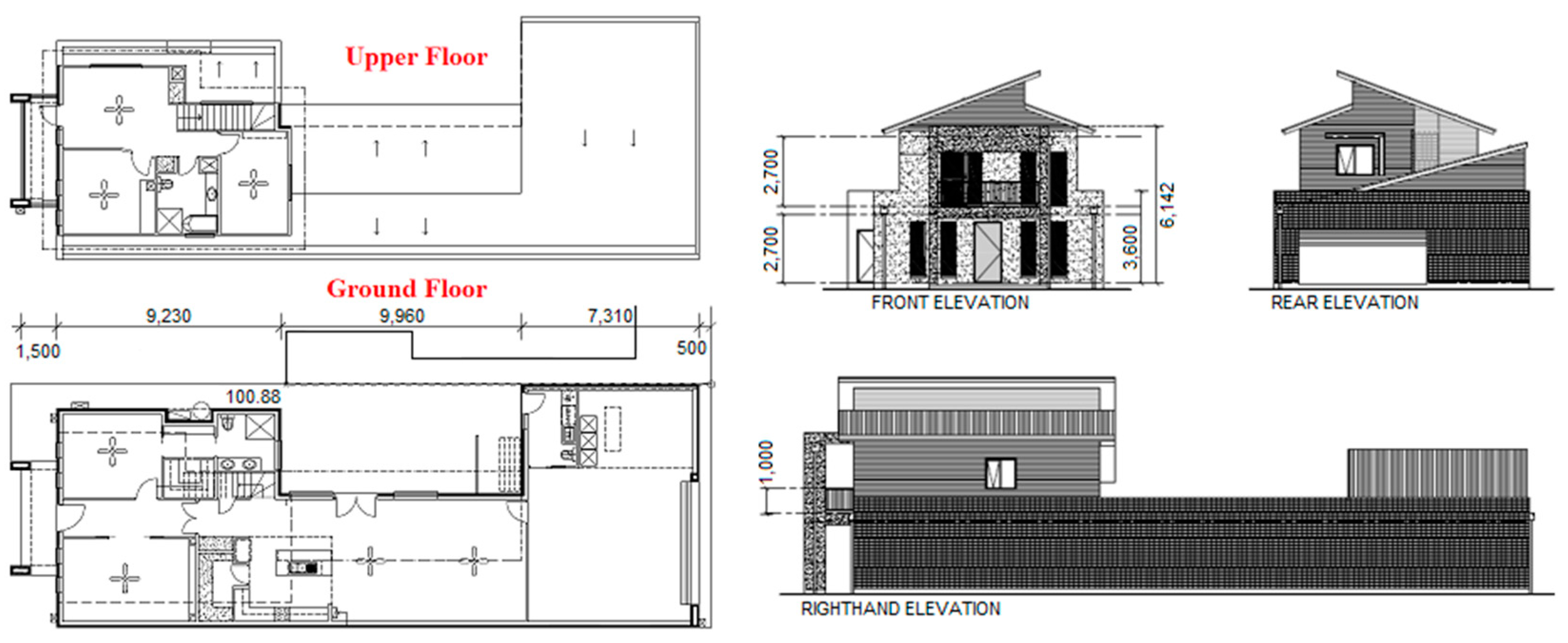
2.1. Building Archetype and Structural Information

The building form selected for this study is a typical brick-veneer double-storey dwelling that has become increasingly adopted for new housing developments in Australia, particularly in those regions of a mild temperate climate. Such a building type is popular for having a light-weight frame structure of steel or timber members and being efficient to construct with modular and prefabricated components, as a more affordable and energy-efficient alternative to traditional double-brick dwellings for urban infill and regeneration.
As shown in Figure 1, the particular dwelling is a two-storey house with a total floor area of 287.5 m2, situated in a residential precinct in one of the north-eastern suburbs of Adelaide, South Australia. The lower floor was built with concrete slab on the ground, a hard surface in living and wet areas, and carpet in bedrooms and the lounge room. The upper floor was constructed with low-emission 22 mm particle board, multiple-layer steel truss made of 1 mm thickness C-channel components, a hard surface in wet areas, and timber/carpet in bedrooms and passages. The external wall of the ground floor is constructed with 110 mm solid bricks, while that of the upper floor used steel-mashed mortar wall panels. The internal walls of both storeys are 15 mm plasterboard board, with a frame (steel/timber) and Bradford glass wool insulation R2.5 in external living areas. The main load-bearing elements of the building includes C-channel beams surrounding the outer perimeter and 5 mm thickness rectangular hollow section (RHS) steel poles. Regarding the windows and roof, double-glazed aluminium windows (with 10 mm air gaps) with Holland style blinds were applied, while the roof is made of Colourbond steel and 13 mm plasterboard (filled with Bradford glass wool insulation R4.0 to under roof ceilings and Bradford glass wool insulation R3.0 to under floor ceilings).
In this study, there are three scenarios employed for comparative studies to identify the embodied carbon benefits contributed by the building frame with different materials, namely steel, timber, and steel-timber composite. The assessment was conducted considering the following assumptions:
(a)
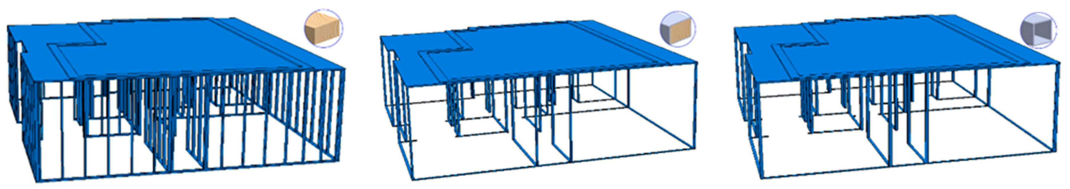
To explore, evaluate, and compare the impact of embodied carbon changes contributed by different building frames, only the building frame materials (namely steel, timber, and steel-timber composite) are different in the three currently considered scenarios, while the other building enclosure/envelope structures remain unchanged.
(b)
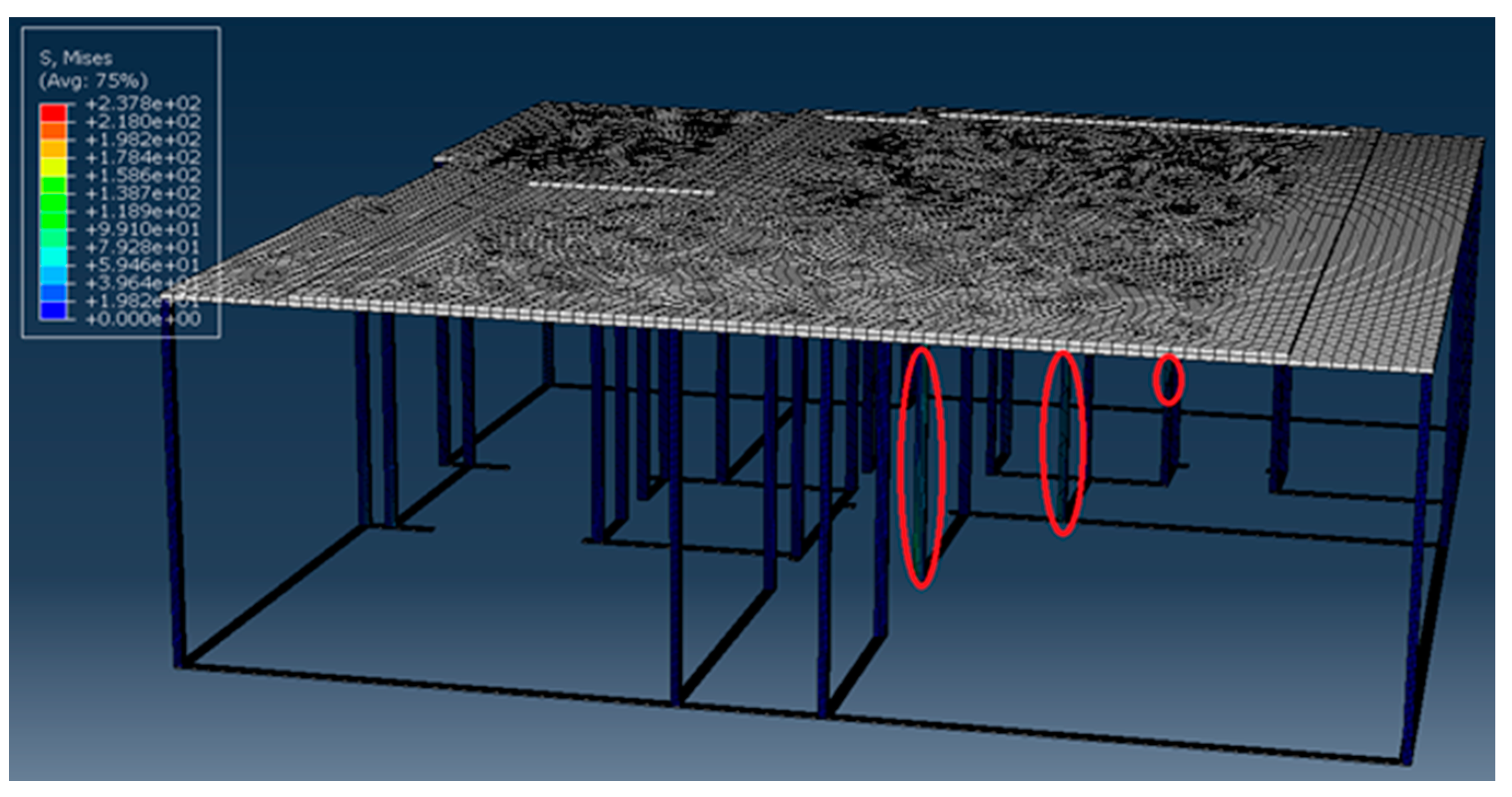
The dimensions of various components of the building frame are determined using Finite Element Analysis (FEA), to ensure that the entire building frame has sufficient structural strength. A safety factor of 2.0 was set for the FEA simulations (the recommended safety factor in the local building code ranged between 1.5 and 2.5).
(c)
The loading on the ground-floor frame was considered to be the entire weight of the upper floor, including the enclosure, floor, furniture, and appliances.
(d)
A 10% amplitude has been applied in the dynamic explicit FEA simulations to ensure that the structures are of sufficient dynamic stabilities.
(e)
The change in the building frame has a limited impact on its thermal performance and thus would not significantly affect the operational carbon of buildings.

2.2. Modelling and Assessment Methods

A modelling strategy and framework is developed to facilitate the scenario analysis of buildings with different frame types, i.e., timber frame (TF), timber–steel composite frame (TSCF), and steel frame (SF), where their embodied carbon and cost implications are assessed and compared within the system boundary discussed in the previous section. As shown in Figure 1, the simulation method integrated with the Finite Element Analysis (FEA) to maximize the loading potential of building materials aimed to reduce the overall embodied carbon emissions and costs. The assessment is underpinned by a modelling and simulation process of four essential phases, as depicted in Figure 2.
In Phase 1, a building design model is first analysed to extract key parametrical information and data to establish the profiles of the building structure, bill of materials required, and building mass derived to support modelling, simulations, and assessments in the phases to follow. Phase 2 is structured to investigate the optimal design of building frame components aided by FEA simulations, aiming for maximum loading capability with minimum embodied carbon and costs. As demonstrated in the literature review, timber frame components are widely recognized as more sustainable with a comparable cost to steel components for buildings, considering their lower carbon intensity and significant ‘carbon sink’ effects at source during the growth phase of trees. Therefore, the optimal design of TSCF components can be achieved by reducing the intensity of steel use in manufacturing frame materials by modifying the dimensions of steel skin and timber filler. FEA simulations are employed to ensure that the TF, SF, and TSCF components designed can meet the expected stability and reliability criteria and to validate parametrical designs for the comparative analysis. Where, the load on the ground-floor frame contributed by the upper floor is derived based on the material features listed in Appendix A. For its versatility and advanced analysis capabilities, Abaqus/CAE 2020 is adopted to perform the FEA modelling and simulation analysis on the behaviour of building structures under various loading conditions. In Phase 3, the stability and reliability of the entire building frame was further validated with FEA simulations, especially for the building frame using timber–steel composite materials (which have not been widely used in brick-veneer building construction). The last phase, i.e., Phase 4, focused on embodied carbon and cost assessments based on the scenario analysis of different frame material options. As shown in Appendix A, a carbon intensity inventory for building components is compiled to enable calculations of embodied carbon and cost implications, based on the data and system boundary introduced in the previous section. The assessments also take into account construction and maintenance factors, including waste ratios and replacement cycles, as well as the costs and carbon emissions from the construction and maintenance services. The carbon and cost measures are expressed as kg CO2-e and thousand Australian dollars (k AUD) per square meter of building floor area, respectively, for the main categories of building components (including envelope, frame, roof, internal partitions, substructure, as well as fitments). In addition, the intensities of embodied carbon and cost of building components are further examined as initial and recurrent intensities, which can be involved to highlight the carbon and cost performances of different stages over the entire lifespan.
To enable the proposed process and methods, in this study, the carbon intensity data and the scenario analysis draws up the Precinct Carbon Assessment (PCA) tool, which was developed from previous research [20] and comprises three levels of modelling that suit the needs of different end-users, such as urban planners and government agencies for development planning, building, and construction practitioners for carbon assessment at the building level and architects and building developers for component and material selections in building design and/or project management decisions. In this study, the building level modelling of the PCA tool is utilized to examine the embodied carbon of buildings with three different material types for the building frame. Similar to the embodied carbon assessment, the cost is calculated with unit costs of building elements and the related consumption of such elements, as well as construction and maintenance costs. Also, in order to ensure the comparability of different scenarios for the building frame, other building components and materials are assumed as unaffected by changes of frame types in simulations and assessments.

3. Results

This section adopts the PCA tool to evaluate the lifecycle embodied carbon and costs of buildings with three different frame types, followed by a comparative study conducted to identify the impacts of building frame types on their overall embodied carbon footprints and costs, as well as to explore the major contributor to building embodied carbon and costs. Moreover, FEA simulation results validate the design, reliability, and stability of structures, as well as a potential optimal design of building elements to maximize the material performance with lower carbon footprints and costs.

3.1. Building Modelling

The main load-bearing source of the ground-floor structure comes from the self-weight of the upper floor, the weight of furniture and appliances, as well as live mass on the upper level. Figure 3 shows the models of the ground-level structure of the studied building for the three different frame materials, focusing on those major load-bearing structure frame components. The essential modelling parameters for the three frame types include the total building mass and loading, as well as quantities and dimensions of key elements, as listed in Table 1.

3.2. Frame Design and FEA Simulations

As timber-framed and steel-framed brick-veneer townhouses have been widely applied in local construction practices, actual data of frame design have been collected and extracted from various building files and then directly used for the comparative analysis.
For the novel timber–steel composite frame analysed in this study, FEA simulations are used to validate the structural design and parametrical values. Considering the availability of and standards for RHS steel poles, thicknesses including 1.6 mm, 2.0 mm, 2.5 mm, 3.0 mm, 4.0 mm, and 5.0 mm are applied in the FEA simulations. The simulations have been conducted with extreme loads derived from the self-weight of the upper level and load imposed by furnishing and live mass. The results indicate that an individual frame column composed of a single timber filler with a 50 mm × 75 mm cross-section and 3 mm thickness RHS could sufficiently support the required load. Figure 4 demonstrates the Von Mises stress in the timber–steel composite column, with the maximum stress of 215.7 MPa, which is less than the yield stress of steel, 250 MPa. The load on the column is 3.26 MPa with a safe coefficient of 2.0 (1.5–2.5 is recommended in the local building code) and 10% amplitudes for dynamic simulations. A further reduction of the RHS thickness to 2.5 mm also has been simulated. The results, however, indicate that the steel RHS would reach the yield limit with a maximum stress of up to 272.9 MPa. In both scenarios, the ductile damage of the timber filler is not reached, showing that the major failure is related to the RHS wrapped outside. Thus, it is reasonable to conclude that the timber–steel composite material can overcome the buckling of thin-walled RHS and deflection of timber components, making it possible to effectively unleash the potential for building with less frame components and material use.
FEA simulations on the entire building frame structure are conducted to validate the frame and column design with the timber–steel composite components. A load of 0.94 × 10⁻³ MPa (considering a safety coefficient of 2.0) is applied with 10% amplitudes to simulate the load from the upper floor dynamically, for which a rigid body constraint is applied to ensure the load would be spread evenly over the entire area. As shown in Figure 5, the simulation results indicate that the maximum Von Mises stress is 237.8 MPa, which is slightly less than the yield stress of steel 250 MPa, with no deflection observed in any column. This indicates that the whole frame structure is reliable for supporting the load including the self-weight of the upper floor and the 1.4 tons assumed live mass. Thus, the design can be applied for embodied carbon and cost assessments. Further observations from the comprehensive frame FEA simulations also reveal that a cluster of pivotal columns bears the majority of the upper floor’s load. This is evident from Figure 5, where those columns circled in red exhibit notably higher Mises’s stress values, while the remaining columns consistently display lower peak stresses. These findings suggest that, owing to the functionally driven architectural layout, the distribution of the upper-level load among the columns is uneven. Consequently, certain columns are underutilized in terms of their load-bearing capacity. Optimizing the frame’s design by redistributing the columns and reinforcing these critical load-bearing columns has the potential to reduce material consumption in other columns, while upholding the necessary structural stability and reliability.

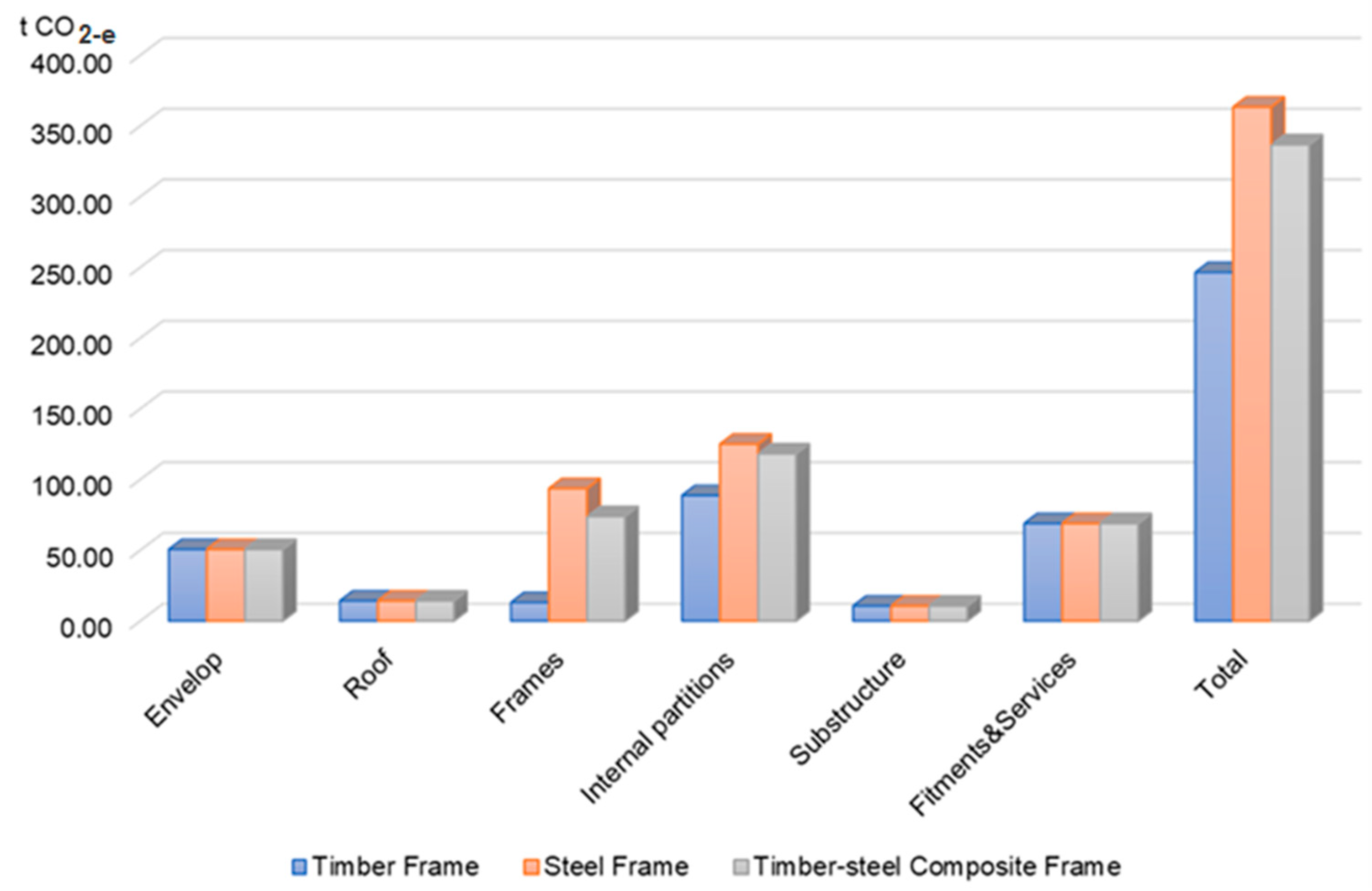
3.3. Embodied Carbon and Cost Assessments

Embodied carbon and cost assessments on those different frame types are applied by using the PCA tool. Based on the local climate and economic factors, supported by market conditions, for building operations, a lifespan of 60 years is selected as the timeframe for the analysis on the building with the three frame options. Figure 6 presents the results of embodied carbon assessment for the three scenarios. Owing to the lowest carbon intensity of the equivalent lifespan, the timber-framed building structure results in the lowest overall embodied carbon emissions, despite having the highest volume of material consumed in the frame construction (e.g., 128 columns used in the timber frame as opposed to 36 steel columns used in the steel frame). The timber–steel composite frame is ranked second as a low-carbon design with significant merits including less material consumption and being lighter in weight, however, at the expense of having a slightly higher equivalent carbon intensity due to the use of 3 mm steel RHS. Comparatively, the steel frame results in the highest embodied carbon signature. This is not solely attributed to the higher carbon intensity of steel elements but also influenced by the associated self-weight increase in the upper structure of the building, which correspondingly requires stronger and heavier columns to support the load. Overall, TF, SF, and TSCF building designs have the total embodied carbon intensities per square meter floor area as 737.29 kg CO2-e/m2, 1144.17 kg CO2-e/m2, and 1051.41 kg CO2-e/m2, respectively.
Figure 7 demonstrates a further breakdown of building total embodied carbon in the categories as internal partitions, envelop, roof, frame, and substructure, as well as fitments and services. Among those, the internal partitions, including the internal wall, floor, windows, doors, and stairs, are the main contributors to building embodied carbon emissions across all the three building frame scenarios. For the timber-framed building design, the fitments and services represent the second major contributors to the embodied carbon. For both the steel-framed building and the timber–steel composite framed building, however, the frames are the second largest source of embodied carbon emissions. This is mainly due to the bulk use of carbon-intensive steel elements for the structure components. In addition, the envelop also has a significant role in adding to the embodied carbon emissions in all the three scenarios, which is caused by constructing with bricks for the veneer. In light of these, low-carbon light materials are the key consideration towards a sustainable green building.
Figure 8 shows the embodied carbon assessment results of elements in the three scenarios. As shown in the bar chart, internal partitions and frames are the two largest pieces of building embodied carbon emissions. In timber-framed buildings, the embodied carbon of fitments and services constitutes a larger proportion, as this building type exhibits significantly lower total embodied carbon than that of the other two building types. While the embodied carbon of fitments and services takes a higher proportion in timber-framed buildings, since this type of building has significantly lower total embodied carbon compared to the other two building types. Further examination of the data reveals that, although both internal partitions and frames have significant carbon footprints, they originate from different sources. The elevated life cycle embodied carbon of internal partitions can be attributed to the increased recurrent embodied carbon resulting from building renovations throughout their lifespan. In contrast, the frame’s carbon footprint is primarily driven by the high embodied carbon intensities of its materials and the overall material consumption.
Compared with the embodied carbon assessment results, the life cycle cost assessments based on the three building frame types show different patterns. There is slight difference in the three scenarios, which could be attributed to the insignificant price gap between steel and timber materials at the local market. The per square meter life cycle costs of the TF, the SF, and the TSCF building scenarios are estimated as 2276.05 AUD/m2, 2373.26 AUD/m2, and 2472.03 AUD/m2, respectively. As shown in Figure 9, the SF building is of the highest cost, followed by the TSCF type. The TF type is the most economic option. However, the cost disparity between the SF building and the TSCF building is 4.16%, while the difference between the TF building and the TSCF building is 4.27%. Such minor differences can be attributed to the slightly higher costs of steel components; although, in total, the amount of steel components used in the SF building construction is much less (e.g., there are 128 columns used to build a timber frame, while only 36 columns are used in the steel and timber–steel composite frames).
Figure 10 demonstrates the further breakdown of building life cycle costs. As shown in this figure, the internal partition occupies the largest proportion of the building’s life cycle cost in all the three scenarios, taking up to 51.40% of the total. This could be attributed to the high recurrent costs associated with renovations over the building’s lifespan. Further obversions indicate that the floor and the internal walls are the main contributors to the costs associated with internal partitions. Among all the main categories of building components, the substructure comes up as the second largest contributor to the building’s life cycle costs due to the cost-intensive concrete and reinforce steel involved in the construction.

4. Discussion

The results of the comparative analysis on the three building frame types and their embodied carbon and cost implications reveal several key findings that can help to provide insights for making informed planning and design decisions.
For the building type studied, the overall self-weight assessments indicate that the TSCF offers a more significant load reduction, up to 15%, for the upper-level structure when compared to the SF. This self-weight reduction is crucial for improving the load-bearing capacity of the underlying structure. It also has positive implications for further optimizing the lower-level frame, reducing the consumption of frame materials. Although the TSCF is largely on par with the TF in relation to the total building mass, the FEA simulations applied to single columns show that a TSCF column can have 7.41% less cross-sectional area than that of a timber column, while providing the same structural performance. A TSCF column combines advantages of both steel and timber and thus can effectively overcome the deflection of long timber elements and the buckling of thin-walled steel RHS. In addition, the FEA simulation also identified that to sufficiently support the load, a minimum thickness of 3 mm steel RHS is required with the timber filler of 50 mm × 75 mm. Otherwise, with the Von Mises yield limit reached, buckling would appear in the steel RHS shell.
Also, the FEA simulations conducted on the whole building structure have validated the feasibility and reliability of the TSCF, which features a 3 mm thick steel RHS shell, at a system perspective. Additionally, the simulation results also reveal that a few critical columns bear most of the load from the self-weight of the upper-level structure, with the other columns exhibiting much lower peak stresses. Consequently, by rearranging the columns and reinforcing those critical ones, the TSCF can offer opportunities for optimized frame designs and potentially lead to a reduction in the volume of material use for the other columns, supporting practices of “Build with Less”. Such optimization would also help to lower the total embodied carbon and cost of the entire frame.
In terms of embodied carbon, the assessments confirm that the TF design exhibits the lowest embodied carbon per floor area, measuring at 737.29 kg CO2-e/m2, followed by the TSCF at 1051.41 kg CO2-e/m2. In contrast, the SF ranks as the highest in embodied carbon intensity among the three frame types, with a value of 1144.17 kg CO2-e/m2, which is nearly 1.6 times higher than that of the TF. It is important to note that, in comparison to previously reported embodied carbon intensities in references [15,16], all three frame types in our study have considerably higher values. This discrepancy can likely be attributed to varying functional requirements and different reginal building criteria, as well as alternative settings in building lifespans, LCA boundaries, and renovation schemes. On the other hand, the TSCF boasts superior mechanical properties and structural stability when compared to the TF, resulting in a roughly 42.6% increase in embodied carbon intensity. However, it is worth mentioning that our study assumes a fixed building lifespan of 60 years for all three frame types, without considering frame replacement or repair. Considering the potential impacts of occupancy and environmental factors, the actual service lives of these frame types may vary due to differences in their material properties. Therefore, an extended lifespan setting could also influence the life-cycle embodied carbon signature by factoring in recurrent embodied carbon associated with the maintenance or replacement of structural elements.
The embodied carbon analysis also highlights that, in addition to the frame, the brickwork is also a main contributor to the embodied carbon of the building across all three scenarios, taking up 14–21% of the total embodied carbon signature. Considering that the carbon intensity of brickwork (which is 167.99 kg CO2-e/m2) is much higher than that of steel-reinforced external wall panels (42.5 kg CO2-e/m2), adopting a modular building design with timber wall panels has a potential to save over 74.7% embodied carbon in external wall construction. This can be attributed to reduction in the overall load and thus less material usage for the building frame. Therefore, a modular building with timber wall panels and the TSCF presents an ideal solution to provide prominent strengths with light weight, high stability, and reliable performance, as well as low embodied carbon signature. Moreover, replacing bricks with timber modular panels can contribute to further decarbonization of the building, as timber, when harvested responsibly through sustainable forest management practices, is an effective sink for sequestered carbon dioxide from the atmosphere.
Furthermore, it is understood that the current design scenarios for the building frame appear rather conservative with much overdesign for the safety factor, which does not fully utilize the performance of the frame material. Thus, further optimal designs of building frames validated with FEA simulations can offer greater potential for the development of light weight and lower carbon buildings.

5. Conclusions

Due to the ongoing rapid growth of urbanization, the imperative to decarbonize the built environment becomes a prominent goal in the pursuit of global sustainability. In this study, an integrated approach is applied to assess embodied carbon and life cycle cost impacts of three different building structures, i.e., timber-framed (TF), steel-framed (SF), and the timber–steel composite (TSCF) framed, scaffolded with Finite Element Analysis (FEA) simulations for strength and stability for different design options. A light-weight frame-structured residential building type is examined as the data source for the modelling and simulations. The results of the comparative scenario analysis highlight that both TF structures and TSCF structures have notable advantages over their SF counterpart for embodied carbon saving and building load reduction. The lifecycle cost assessments also reveal a promising cost saving potential of TF and TSCF structures for the application. Meanwhile, the simulations further demonstrate that TSCF materials in particular can have significant benefits for mechanical property and stability of lightweight building structures in overcoming the deflection problem of long TF components and the buckling of thin-walled SF members.
In summary, the research suggests that TF structures are currently an economically viable choice with minimal carbon emissions for constructing lightweight buildings. It also highlights the potential of TSCF structures to reduce material usage through design optimization. To address the lack of data on TSCF components, the study employs FEA simulations to determine the thickness of RHS and the necessary timber filler for TSCF columns and to confirm the stability and reliability of building structures. However, the study does not fully delve into FEA simulations for optimizing structural designs to reduce their carbon footprint and costs through material conservation at this stage. This underscores the need for future research to explore the development and application of innovative composite materials with optimal mechanical and structural properties for lightweight buildings, leading to further reductions in carbon emissions and lifecycle costs. Furthermore, the study identifies brickwork as a significant contributor to embodied carbon in all three scenarios, which have not been involved with alternative wall solutions. Given that the carbon intensity per square meter of brickwork is much higher than that of external wall panels, investigating design and construction options for modular buildings with timber wall panels could significantly contribute to decarbonizing the construction industry.

Author Contributions

Conceptualization, K.X. and R.R.; methodology, B.H.; software, B.H.; validation, B.H., K.X. and R.R.; formal analysis, B.H.; investigation, B.H.; resources, B.H. and R.R.; data curation, B.H.; writing—original draft preparation, B.H.; writing—review and editing, K.X. and R.R.; project administration, B.H.; funding acquisition, B.H. and K.X. All authors have read and agreed to the published version of the manuscript.

Funding

Funding that permitted this research was granted by the National Natural Science Foundation of China, grant number 51908064; Changsha University of Science and Technology by the program “International Collaborative Research Underpinning Double First-Class University Construction”, grant numbers 2018IC19 and 2019IC17.

Institutional Review Board Statement

Not applicable.

Informed Consent Statement

Not applicable.

Data Availability Statement

Not applicable.

Acknowledgments

The authors would like to acknowledge the National Natural Science Foundation of China, University of South Australia, and Changsha University of Science and Technology for the funding opportunities and financial support.

Conflicts of Interest

The authors declare no conflict of interest.

Appendix A

Table A1. Material features and intensities.
Building ElementsUnitDensity
(kg/Unit)
Carbon Intensity
(kg CO2-e/Unit)
Plaster (cement: sand 1:4)per m2 wall22.506.75
Plasterboard (10 mm thickness)per m210.007.50
Plasterboard (20 mm thickness)per m220.0015.00
Brickworkper m2 envelop197.63167.99
Rockwool batt R2.0per m2 floor1.250.75
Rockwool batt R2.5per m2 wall1.951.17
Rockwool batt R4.0per m2 ceiling5.283.17
Mortarper m2 wall13.003.25
Timber frameper m2 wall12.763.19
Steel frameper m2 wall40.0060.00
Steel-reinforced wall panelper m2 wall50.0042.50
Colourbond roof-steelper m2 roof4.909.90
Roof truss-timberper m2 roof16.54.13
Roof truss-steelper m2 roof20.0030.00
Gutteringper meter1.2614.40
Glass-windowper m210.005.00
Window frame-timberper m216.300.59
Window frame-aluminiumper m26.0013.26
External door-timberper m232.5010.00
Internal door-timberper m212.646.49
Stairs-timberper storey350.00250.00
Floor-carpet 10 + felt underlay 10per m2 floor area2.2528
Floor-timber trussper m2 floor area25.526.38
Floor-steel trussper m2 floor area12.7625.52
Drainsper m2 floor area0.309.95
Ceramic tileper m217.0030.00
Concrete: standardper m2 floor area240.0030.00
* Cabinets per m2 floor area89.2224.78
* Oven/hobper each50.0080.00
* Air-conditionerper each58.00450.00
* Dish washerper each70.00400.00
* Fridgeper each300.00200.00
* Wash machineper each80.00350.00
Piping per m2 floor area1.3140.43
Steel sinksper each6.00104.94
* WCsper each12.0012.24
Handbasinsper each13.0013.26
Taps/fittingsper each3.6016.92
* Bathsper each6.8035.77
Water Serviceper each70.001852.90
Wire per storey23.50260.15
Fittings per room0.105.26
C-channel steel structureper linear meter57.6886.52
* Bedper each160.00270.00
* Deskper each40.0080.00
* Sofaper each60.00190.00
Pavers-concreteper m2 floor area80.6020.15
Pergola-timberper m2 floor area10.706.31
Fences-timberper linear meter8.404.96
* Garage doorper m26.5045.00
Shed-steelper m2 floor area3.6043.92
Steel RHS poleper linear meter16.3025.26
* Estimated values for appliances.

References

  1. Ching, E.; Carstensen, J.V. Truss topology optimization of timber–steel structures for reduced embodied carbon design. Eng. Struct. 2022, 252, 113540. [Google Scholar] [CrossRef]
  2. Zhang, Y.; Teoh, B.K.; Wu, M.; Chen, J.; Zhang, L. Data-driven estimation of building energy consumption and GHG emissions using explainable artificial intelligence. Energy 2023, 262, 125468. [Google Scholar] [CrossRef]
  3. Ahmed Ali, K.; Ahmad, M.I.; Yusup, Y. Issues, Impacts, and Mitigations of Carbon Dioxide Emissions in the Building Sector. Sustainability 2020, 12, 7427. [Google Scholar] [CrossRef]
  4. Huang, B.; Xing, K.; Ness, D.; Liao, L.L.; Huang, K.; Xie, P.L.; Huang, J.L. Rethinking carbon–neutral built environment: Urban dynamics and scenario analysis. Energy Build. 2022, 255, 111672. [Google Scholar] [CrossRef]
  5. Pomponi, F.; Moncaster, A. Embodied carbon mitigation and reduction in the built environment—What does the evidence say? J. Environ. Manag. 2016, 181, 687–700. [Google Scholar] [CrossRef] [PubMed]
  6. Chan, M.; Masrom, M.A.N.; Yasin, S.S. Selection of Low-Carbon Building Materials in Construction Projects: Construction Professionals’ Perspectives. Buildings 2022, 12, 486. [Google Scholar] [CrossRef]
  7. Salama, A.; Atif Farag, A.; Eraky, A.; El-Sisi, A.A.; Samir, R. Embodied Carbon Minimization for Single-Story Steel Gable Frames. Buildings 2023, 13, 739. [Google Scholar] [CrossRef]
  8. Hunt, J.; Osorio-Sandoval, C.A. Assessing Embodied Carbon in Structural Models: A Building Information Modelling-Based Approach. Buildings 2023, 13, 1679. [Google Scholar] [CrossRef]
  9. Hawkins, W.; Cooper, S.; Allen, S.; Roynon, J.; Ibell, T. Embodied carbon assessment using a dynamic climate model: Case-study comparison of a concrete, steel and timber building structure. Structures 2021, 33, 90–98. [Google Scholar] [CrossRef]
  10. Robati, M.; Oldfield, P. The embodied carbon of mass timber and concrete buildings in Australia: An uncertainty analysis. Build. Environ. 2022, 214, 108944. [Google Scholar] [CrossRef]
  11. Hafner, A.; Schäfer, S. Comparative LCA study of different timber and mineral buildings and calculation method for substitution factors on building level. J. Clean. Prod. 2018, 167, 630–642. [Google Scholar] [CrossRef]
  12. Morris, F.; Allen, S.; Hawkins, W. On the embodied carbon of structural timber versus steel, and the influence of LCA methodology. Build. Environ. 2021, 206, 108285. [Google Scholar] [CrossRef]
  13. Zeitz, A.; Griffin, C.T.; Dusicka, P. Comparing the embodied carbon and energy of a mass timber structure system to typical steel and concrete alternatives for parking garages. Energy Build. 2019, 199, 126–133. [Google Scholar] [CrossRef]
  14. Chen, Z.; Gu, H.; Bergman, R.D.; Liang, S. Comparative life-cycle assessment of a high-rise mass timber building with an equivalent reinforced concrete alternative using the Athena impact estimator for buildings. Sustainability 2020, 12, 4708. [Google Scholar] [CrossRef]
  15. De Wolf, C.; Hoxha, E.; Hollberg, A.; Fivet, C.; Ochsendorf, J. Database of embodied quantity outputs: Lowering material impacts through engineering. J. Archit. Eng. 2020, 26, 04020016. [Google Scholar] [CrossRef]
  16. Hart, J.; D’Amico, B.; Pomponi, F. Whole-life embodied carbon in multistory buildings: Steel, concrete and timber structures. J. Ind. Ecol. 2021, 25, 403–418. [Google Scholar] [CrossRef]
  17. Skullestad, J.L.; Bohne, R.A.; Lohne, J. High-rise timber buildings as a climate change mitigation measure—A comparative LCA of structural system alternatives. Energy Procedia 2016, 96, 112–123. [Google Scholar] [CrossRef]
  18. Kim, S.; Lee, S.; Na, Y.-J.; Kim, J.T. Conceptual model for LCC-based LCCO2 analysis of apartment buildings. Energy Build. 2013, 64, 285–291. [Google Scholar] [CrossRef]
  19. Fesanghary, M.; Asadi, S.; Geem, Z.W. Design of low-emission and energy-efficient residential buildings using a multi-objective optimization algorithm. Build. Environ. 2012, 49, 245–250. [Google Scholar] [CrossRef]
  20. Xing, K.; Wiedmann, T.; Newton, P.; Huang, B.; Pullen, S. Development of Low-Carbon Urban Forms—Concepts, Tools and Scenario Analysis. In Decarbonising the Built Environment: Charting the Transition; Newton, P., Prasad, D., Sproul, A., White, S., Eds.; Palgrave: Singapore, 2019; Volume 12, pp. 227–244. [Google Scholar]
Figure 1. Floor plans and elevations.
Sustainability 15 15167 g001
Figure 2. A schematic representation of building embodied carbon and cost assessment.
Sustainability 15 15167 g002
Figure 3. Structure of the TF, TSCF, and SF building frames.
Sustainability 15 15167 g003
Figure 4. FEA simulations of timber–steel column: (a) 3 mm RHS and (b) 2.5 mm RHS.
Sustainability 15 15167 g004
Figure 5. FEA simulation of the TSCF.
Sustainability 15 15167 g005
Figure 6. Embodied carbon of the three building types.
Sustainability 15 15167 g006
Figure 7. Embodied carbon breakdown of TF, SF, and TSCF buildings.
Sustainability 15 15167 g007
Figure 8. Elements embodied carbon of TF, SF, and TSCF buildings.
Sustainability 15 15167 g008
Figure 9. Life cycle costs (in AUD) of TF, SF, and TSCF buildings.
Sustainability 15 15167 g009
Figure 10. Life-cycle cost breakdowns for timber, steel, and timber–steel framed building.
Sustainability 15 15167 g010
Table 1. Building frame and mass profiles.
Upper-Level Mass (Tons)Live Mass
(Tons)
Column Size (mm)No. of Columns
TF25.961.445 × 90128
TSCF25.751.450 × 75, 3 mm steel RHS36
SF30.331.485 × 85, 5 mm steel RHS36
Disclaimer/Publisher’s Note: The statements, opinions and data contained in all publications are solely those of the individual author(s) and contributor(s) and not of MDPI and/or the editor(s). MDPI and/or the editor(s) disclaim responsibility for any injury to people or property resulting from any ideas, methods, instructions or products referred to in the content.

