Essay

Simulation Study of a Novel Solar Air-Source Heat Pump Heating System Based on Phase-Change Heat Storage

College of Energy Engineering, Xi’an University of Science and Technology, Xi’an 710054, China
*
Author to whom correspondence should be addressed.
Sustainability 2023, 15(22), 15684; https://doi.org/10.3390/su152215684
Submission received: 17 May 2023 / Revised: 2 June 2023 / Accepted: 9 June 2023 / Published: 7 November 2023
(This article belongs to the Topic Advances in Solar Heating and Cooling)

Abstract

:
A traditional solar air-source heat pump heating system cannot effectively utilize solar energy, and it consumes large amounts of energy when operating during cold nights. Accordingly, a conventional heating system has been improved by phase-change heating to form a new phase-change thermal storage solar air-source heat pump heating system. Based on the TRNSYS simulation platform, a heating simulation study of the improved phase-change heating system was carried out in Xi’an City. The results show that the addition of phase-change thermal storage technology allows the heating system to make better use of solar energy, and the efficiency of the solar collector is increased by 5.9%; the presence of the phase-change material effectively reduces the rate of temperature drop inside the water tank, making the water supply temperature more stable; during the whole heating period, the improved phase-change heating system saved 484.91 kWh of operating energy, showing a very good energy-saving effect.

Graphical Abstract

1. Introduction

To further enhance people’s happiness in their work life, it is essential to create a comfortable office life environment. For cities in cold regions, indoor heating is an integral part of creating a comfortable environment, and indoor heating is inevitably accompanied by energy consumption. In the northern region of China, the energy consumed for indoor heating reached 23% of the total building energy consumption [1]. Energy shortages and environmental pollution are the two major challenges that our country faces [2]. Currently, the use and conversion of environmentally friendly energy sources is the best way to solve the above problems [3,4,5]. Solar energy, a representative of environmentally friendly energy sources, is utilized in photothermal, photovoltaic, photochemical, and photobiological ways [6]. Among them, photothermal utilization is the most important utilization method due to its high conversion efficiency. Solar thermal utilization is generally achieved through solar collectors, by converting solar radiation into heat energy for heating a fluid medium to achieve the purpose of heating. Compared with traditional heating systems using coal and natural gas as fuel, solar heating is pollution-free, economical, and safe.
Solar energy is greatly affected by weather factors and cannot be used at night, so solar collectors (SCs) and air-source heat pumps (ASHPs) are often used as heat sources for heating. Authors have conducted extensive research about solar air-source heat pump heating systems (SASHPHSs) [7,8,9]. Zhan et al. [10] established a solar air-source heat pump simulation heating system for an office building in Qingdao. They concluded that compared with a traditional air-source heat pump system, the system saved 9091 kWh in the heating season under the optimal heat collection area. Zeng et al. [11] evaluated an SASHPHS using TRNSYS 18 software, providing a theoretical basis for the optimal design of the system. Wang et al. [12] investigated the adaptability of an SASHPHS by simulating different regions, and their research showed that the system has strong practicability. Additionally, this system has been carefully studied using experimental methods. Guo et al. [13] found that buildings using SASHPHSs have more remarkable heating performance and more stable room temperature. Sterling and Collins [14] compared an SASHPHS with a traditional electric heating system. The results showed that the SASHPHS has lower operating costs and greatly reduces power consumption. Dikici et al. [15] conducted an experimental test on a combined heating system of solar energy and a heat pump in a room with an area of 60 m2 in Fella, Turkey. Their experiments showed that when the exergy loss of the solar collector was 1.92 kW, the coefficient of performance (COP) of the system reached 3.08.
An SASHPHS has a simple structure and high economy, and it can fully meet the thermal comfort requirements of residents. However, the ASHP running alone at night in winter increases the energy consumption of the system due to the low outdoor temperature. Therefore, scholars have combined phase-change heat storage technology with heating systems to solve this problem. Sun et al. [16] designed a phase-change heat storage solar air-source heat pump system with a unique energy storage condenser. Simulation studies showed that the heating effect of the system was good, and the maximum coefficient of performance of the heat pump was 5.19. The energy-saving effect of the system was very obvious. Yan et al. [17] investigated a new type of solar heat storage air-source heat pump complementary heating system by adding a heat storage tank at the inlet of the ASHP. The simulation results showed that the system improved the inlet air temperature of the ASHP, and the average heating efficiency ratio of the heat pump was increased by 34.87%. Qu et al. [18] conducted an experimental test on a recently developed double-tank latent heat storage solar heat pump heating system in Beijing. It was found that with the use of latent heat storage, the heat collection efficiency was increased to 50%, and the energy efficiency of the system was improved. Zhao et al. [19] designed a solar phase-change thermal storage heating system that improved the utilization rate of solar energy by adding a phase-change heat storage tank. Using ASHP as an auxiliary heat source and a capillary as a radiation end, a heating test of the building was carried out. The results showed that the addition of the phase-change energy storage tank resulted in significant energy savings and that capillary tubes as radiant heating ends created a very pleasant indoor environment.
Based on the research mentioned above, the combination of phase-change materials and an ASAHPHS not only stores and releases collected solar heat reasonably and effectively, but also makes the system run more stably and reduces energy consumption. However, most of the above studies involved the addition of a phase-change energy storage tank to the system to form a double-tank system, which led to an increase in the area of the system. In this study, the ordinary water tank in an SASHPHS was reformed, and the phase-change material was combined with the traditional ordinary water tank to form a new phase-change heat storage solar air-source heat pump heating system. The performance of the phase-change system was analyzed using TRNSYS 18 transient software and compared with that of the traditional solar air-source heat pump heating system before the transformation. The reformed system not only made fuller use of solar energy, but also greatly reduced energy consumption, which was very consistent with the renewable energy development policy.

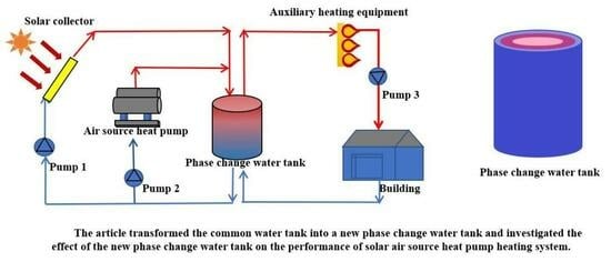
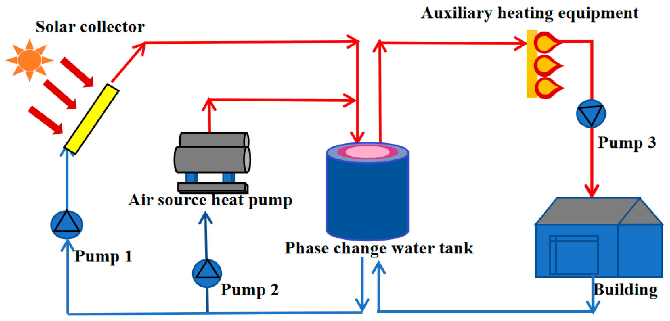
2. Concept of the System

An improved solar air-source heat pump heating system (SASHPHS) based on phase-change heat storage was proposed. The system used solar energy more reasonably and stably. As shown in Figure 1, the system consisted of a solar collector (SC), an air-source heat pump (ASHP), a water pump, a phase-change water tank, auxiliary heating equipment, and a terminal heating building.
According to the change in weather conditions, the system can be switched between three operating modes.
  • The solar collector operates alone.
When there is sufficient solar radiation, cold water flows into the SC through pump 1, the SC heats the water, and the heated water flows directly into the phase-change water tank. This mode directly converts solar energy into thermal energy to heat the system, and the whole process is very energy-saving.
  • The air-source heat pump operates alone.
In the case of rainy or snowy days and nights without solar radiation, the ASHP operates separately to take up the heat load of the building. Cold water enters the ASHP through pump 2, the ASHP heats the water, and the heated water flows directly into the phase-change water tank. A large amount of electricity is consumed in this mode.
  • The solar collector and the air-source heat pump operate together.
When the solar radiation is very low and the heat provided by the SC is not enough to support the entire heat load, the ASHP turns on and heats the cold water together with the solar collector.

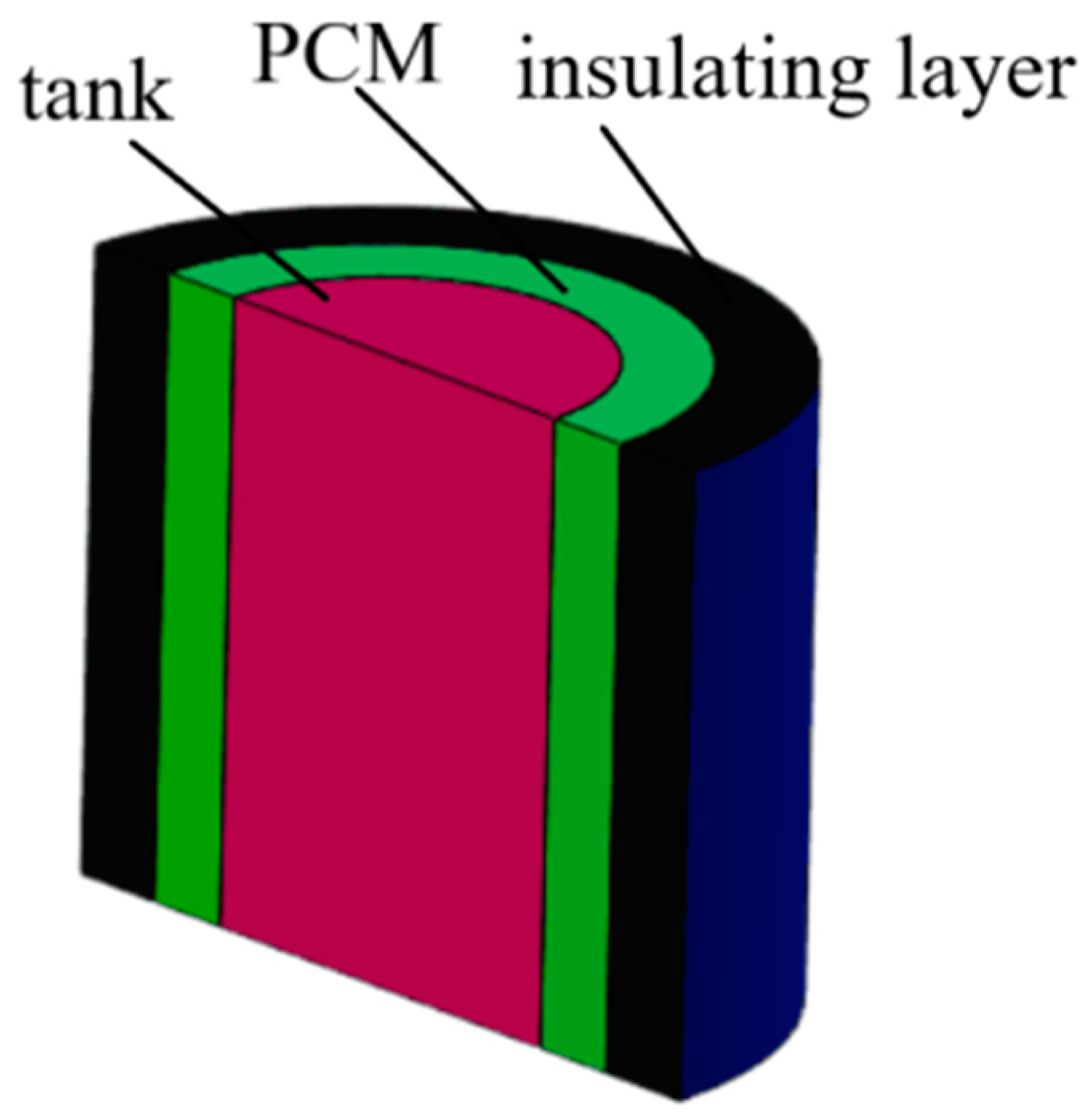
2.1. Phase-Change Water Tank

The phase-change water tank played a key role in storing heat and releasing heat in the SASHPHS based on phase-change heat storage. The ordinary water tank was modified to form a phase-change water tank. A certain thickness of a phase-change material (PCM) was laid on the surface of the ordinary water tank, and finally, the insulation layer was wrapped in the outer layer of the PCM, in which an appropriate expansion space should be reserved. The profile of the phase-change water tank is shown in Figure 2, comprising the water tank, PCM layer, and insulation layer from the inside to the outside. The effective thickness of the PCM layer was 0.12 m.
The Type158 in TRNSYS was used as the component model of the ordinary water tank. There were two inlets and outlets in the upper and lower parts of the water tank, respectively. The cold water obtains the heat provided by SC and ASHP through the inlet and outlet of the heat source side, and the hot water heats the building through the inlet and outlet of the load side. The volume of the water tank was set to 3 m3. The loss coefficient of the upper and lower bottom was 0.6 W/(m2·°C), and the edge loss coefficient was set to 1000 W/(m2·°C) to achieve the heat transfer between the water tank and the phase-change layer and the heat storage and release simulation of the PCM [20].
Phase-change materials are widely used because of their unique heat storage and exothermic properties. Solar heating water systems mainly use low-temperature PCMs (phase-change temperature ≤ 100 °C) for waste heat recovery and solar energy storage. Low-temperature PCMs mainly include paraffin, inorganic salt hydrate, fatty acids, and so on. The latent heat of phase change was given priority in this study, so fatty acid phase-change materials were selected. They not only have the advantages of large latent heat, non-toxicity, and no super-cooling, but also can be well compatible with traditional materials and less corrosive. Myristic acid (MA), a type of fatty acid, is a white to yellowish-white hard solid with a melting point of 52 to 54 °C. This temperature is sufficient for direct heating of solar hot water in winter [21]. It has a high latent heat of phase change and low sub-cooling, which is suitable for filling the phase-change tank. However, it has low thermal conductivity and low heat storage and discharge efficiency. There is also the possibility of liquid leakage during the solid–liquid phase change. Therefore, expanded graphite (EG) was added to myristic acid to improve the thermal conductivity of the phase-change material while retaining its advantages by using the adsorption of graphite on liquid fatty acid species [22,23]. The addition of EG greatly improved the heat storage and release rate of the phase-change unit, strengthened the heat transfer performance, and prevented the leakage of the material to some extent [24]. The MA/EG composite phase-change material has high energy storage density and good chemical stability. In addition, it has a low price and is very economical [25]. The composite phase-change material was encapsulated into a cylindrical container and placed inside a thermal storage tank for heat storage and discharge testing [26]. The results showed that the heat storage and release of the phase-change material were very stable, and the tank provided hot water with less temperature fluctuation. Therefore, the MA/EG composite phase-change material was selected as the filler for the phase-change tank. The specific parameters of the PCM are shown in Table 1.

2.2. Specific Parameters of Other Components

As the device is mainly operated in the winter, good anti-freeze performance was required, and the highest possible heat collection efficiency was obtained. Therefore, an evacuated tube collector (ETC) was selected; it had an area of 50 m2, an installation inclination of 25°, and a flow rate of 50 kg/h per unit area. The flow of pump 1, pump 2, and pump 3 was 2500 kg/h, 2500 kg/h, and 2000 kg/h, respectively, and the power was 0.6 kW, 0.6 kW, and 0.5 kW, respectively. The component type 941 air-source heat pump was selected, and its rated heating capacity was 12.5 kW. The TRNSYS type 659 electric heating component was selected, and its setting temperature was 40 °C. The parameters of the core modules are listed in Table 2.

3. Construction of System Model

3.1. Mathematical Models

A SC can convert solar radiation into heat energy for fluid heating. The useful heat energy obtained by the fluid flowing through the collector can be calculated by applying the following:
Q u = m C p T o u t T i n
where Qu is the useful thermal energy of the fluid, kJ/h; m is the mass flow of water entering the collector, kg/h; Cp is the constant-pressure specific heat of water, kJ/(kg K); Tout and Tin are the collector outlet and inlet water temperature, respectively, K.
The efficiency of the collector is given by the following:
η = Q u A I c
where A is the lighting area of the collector, m2; Ic is the total solar radiation received by the solar collector, kJ/(h·m2).
The evaluation index of the ASHP is the performance coefficient COP of the heat pump unit under actual operating conditions:
C O P = Q H W H
where QH is the heating capacity of the air-source heat pump unit, kW; WH is the power consumption of the compressor, kW.
The main heat transfer process in a phase-change tank is heat transfer between water and the PCM. Without considering the influence of water flow on heat exchange, the heat storage of the phase-change tank [20] is as follows:
Q = M T P C M T c C s + λ + T h T P C M C l + M w C p T h T c
where Q is the heat storage of the phase-change water tank, kJ; M is the quality of the PCM filled in the tank, kg; TPCM is the phase-change temperature of the PCM, °C; TC is the initial temperature of the phase-change water tank, °C; CS is the solid specific heat capacity of the PCM, kJ/(kg·°C); λ is the latent heat of the PCM, kJ/kg; Th is the temperature of the heat storage side of the phase-change water tank, °C; Cl is the liquid specific heat capacity of the PCM, kJ/(kg·°C); Mw is the total mass of water in the phase-change water tank, kg; Cp is the constant-pressure specific heat of water, kJ/(kg·°C).
In this paper, a model of an SASHPHS based on phase-change heat storage was established. The heat conduction and convection were more complicated in the heat storage and heat release process of the PCM. So, the following assumptions were made when the system model was established: the sensible heat change in the phase-change process was neglected; the change in PCM heat storage and release performance after multiphase-change was ignored; the heat loss from the insulation layer was neglected.

3.2. Simulation Validation

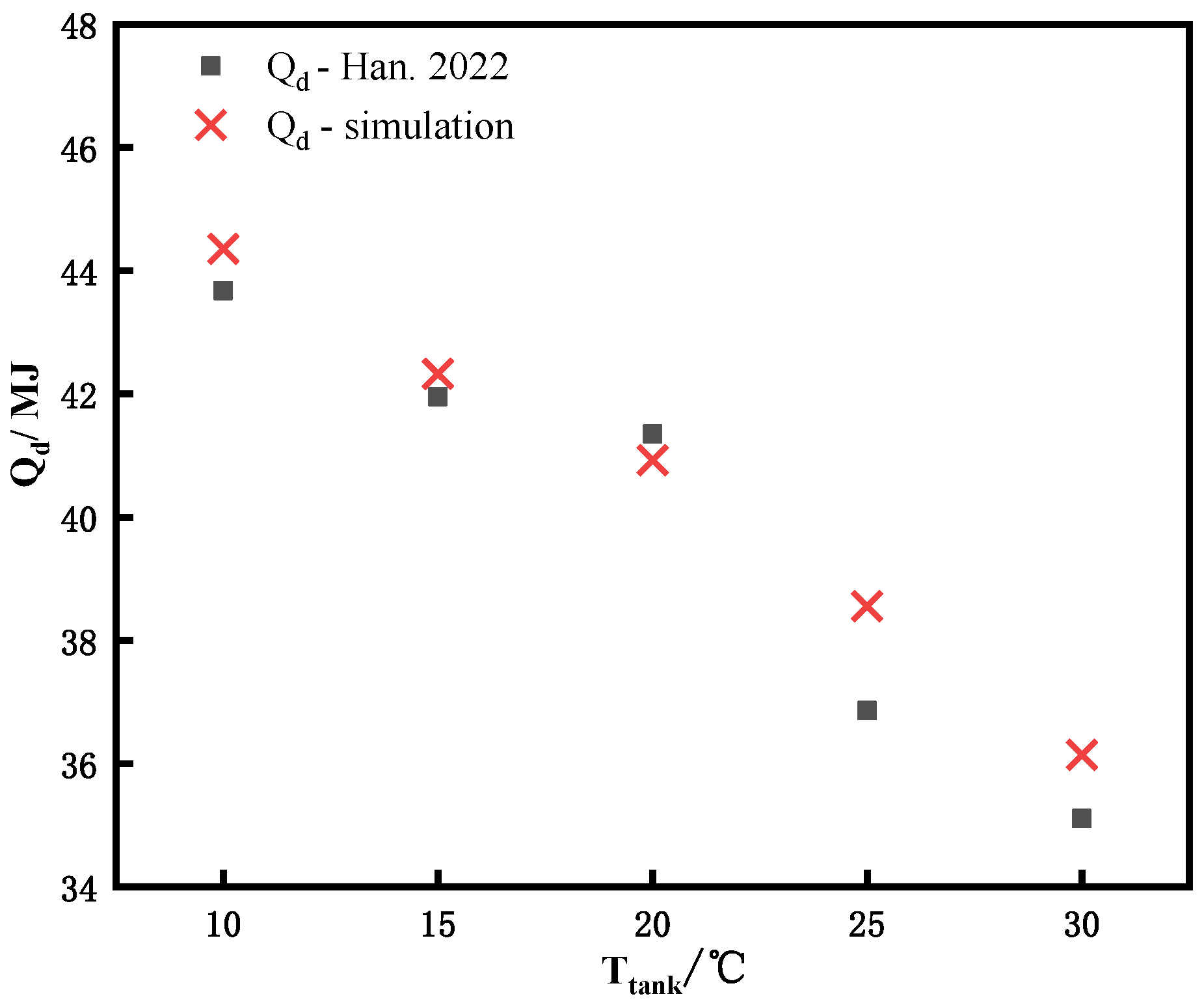
  • As the core equipment of the heating system in this study, the models of the ETC, ASHP, and phase-change water tank were verified. Han et al. [27] conducted an experimental study on a solar water heating system in Tianjin and tested the daily useful heat of an ETC. The meteorological parameters of the ETC and water tank were set in the traditional ASAHPHS in this study. The ASHP loop and the heating loop in the traditional heating system were closed, and then the solar heat collection loop was simulated. At different initial temperatures of the tank, the experimental and simulated values of the useful heat of the collector were compared, as shown in Figure 3. It can be clearly seen that the variation trend of the simulated value was consistent with that of the experimental value, and the relative error between them was 4.89% at most.
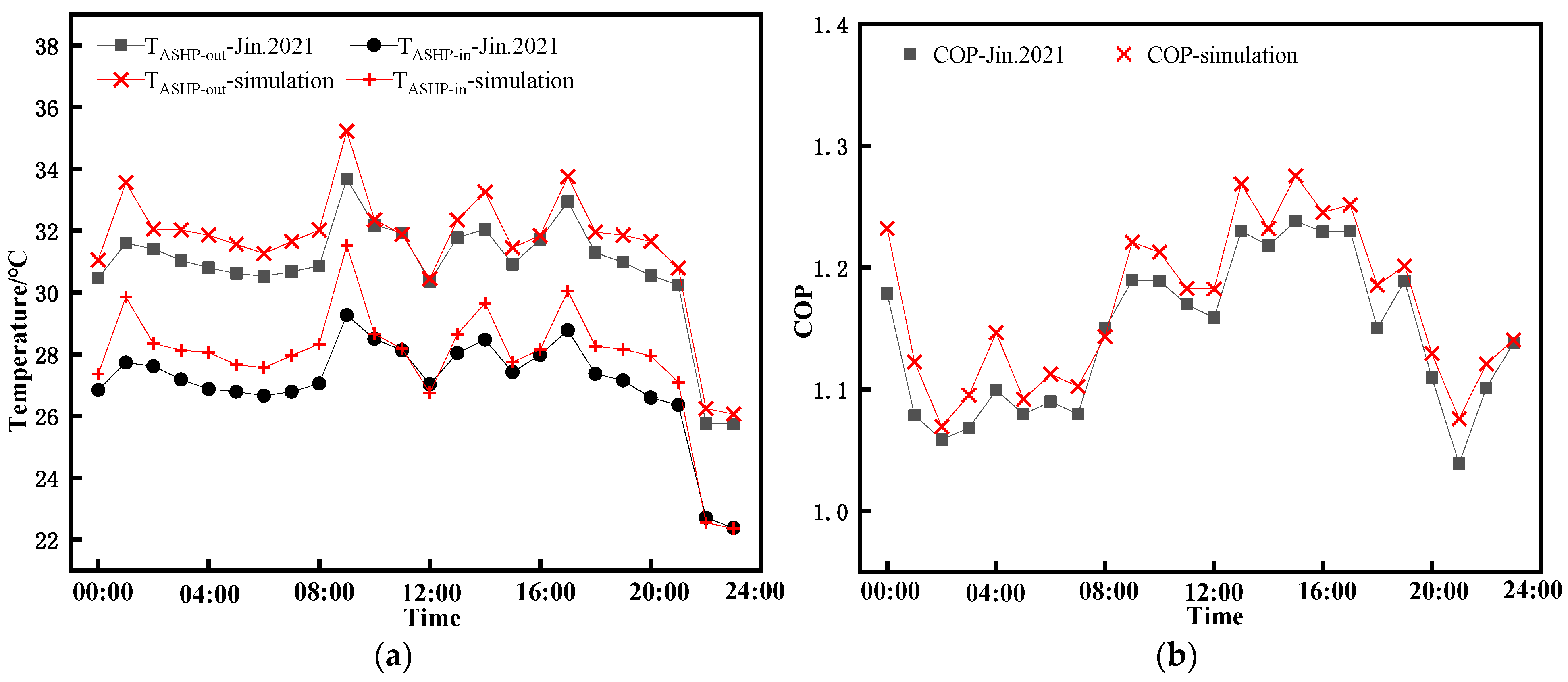
  • Jin et al. [28] conducted a separate air-source heat pump heating test in Baotou. The solar heat collecting loop and auxiliary heating equipment in the traditional system in this paper were closed, and relevant parameters (weather, air-source heat pump, etc.) in the experiment were set in the system model in this paper for simulation. The experimental and simulated values of the temperature difference between the inlet and outlet of the ASHP are shown in Figure 4a. Figure 4b shows the comparison between the experimental values and the simulated values of COP of the ASHP. As can be seen from Figure 4, the experimental values and simulated values had the same variation trend, but there were still errors between them. All relative errors were kept within ±9%.
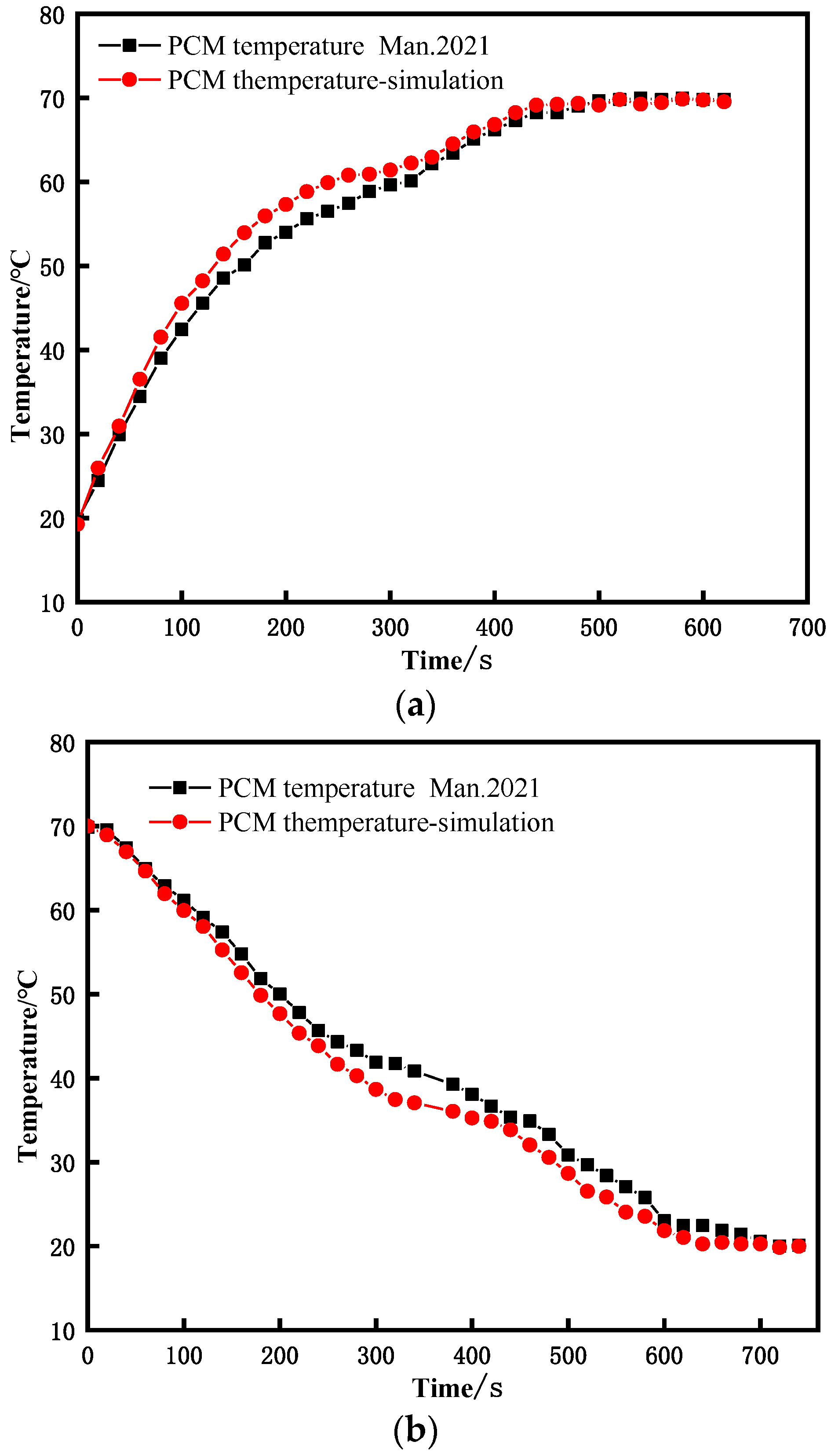
  • Man [29] investigated the thermal performance of a phase-change water tank under the climatic conditions of Jinzhou. The phase-change water tank designed by Man [29] had an inner diameter of 75 cm, an outer diameter of 90 cm, and a phase-change layer thickness of 15 cm. The tank was filled with myristic acid as the PCM. The parameters of the water tank and PCM in [29] were set in the model of the phase-change water tank in this paper to verify the heat storage and release of the phase-change water tank. As can be seen from Figure 5, during the heat storage and release process, the change trend of PCM temperature was consistent with the literature. However, there was still a difference in temperature, which was within a 10 percent margin of error.
  • According to the variation trend of the above parameters and the range of relative errors, the results of the component model established in this paper can be considered to be reliable. The reasons for the error may be the instability of meteorological parameters (wind change and cloud change in the experiment), the initial temperature fluctuation of the tank, the heat loss of the pipeline, and the operation of the system.

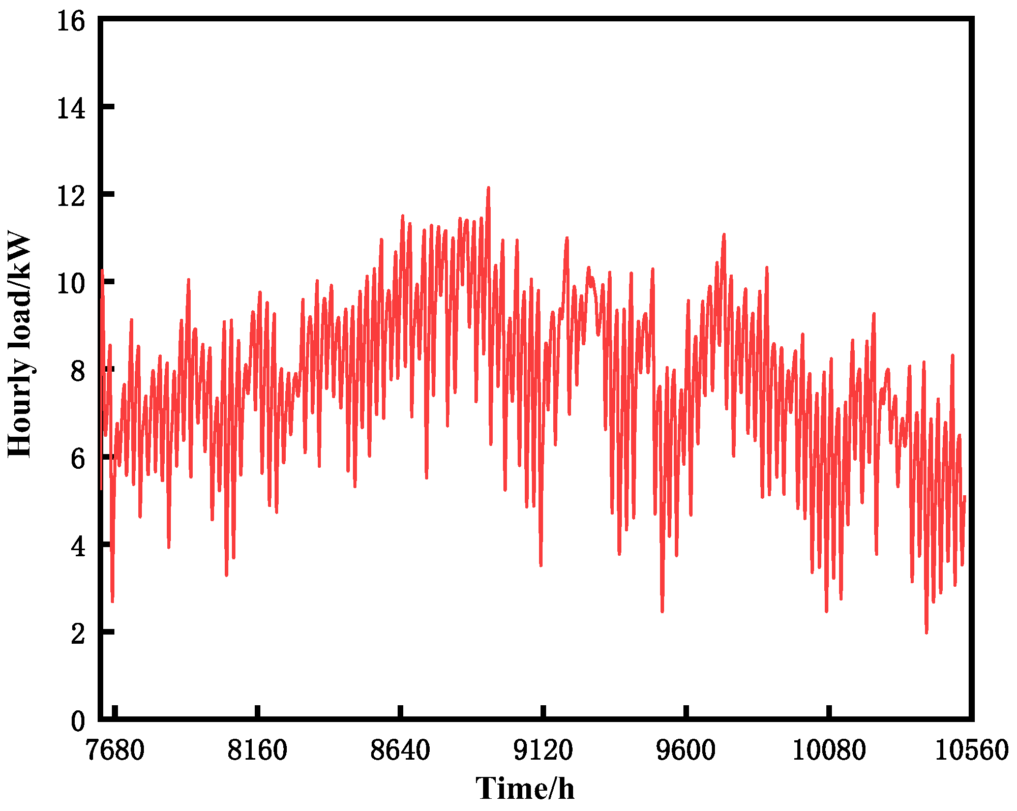
3.3. Heat Load Simulation

An office building in Xi’an was selected as the end building of the heating system in this study. The total heating area of the building was 150 m2. The indoor heating design temperature of the building was 20 °C, and the heating water temperature was 40 °C. The typical meteorological year file of Xi’an was chosen, and the heating period was set from 15 November to 15 March of the following year. By setting building parameters in TRNBUILD, the hourly heat load of the building during the heating cycle was calculated, as shown in Figure 6. The cumulative heat load of the whole heating period was 21,301.01 kWh, and the maximum hourly heat load was 11.91 kW.

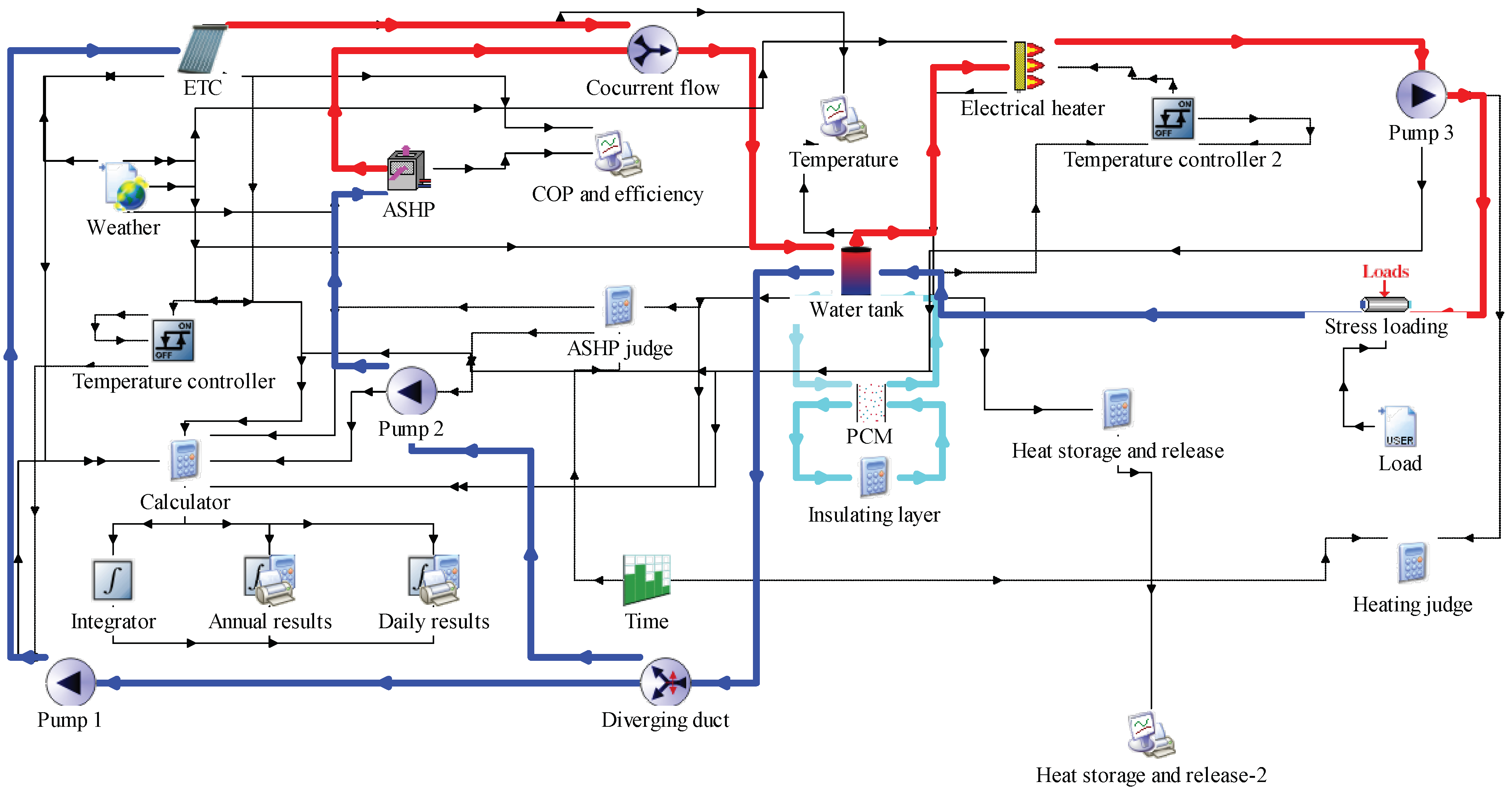
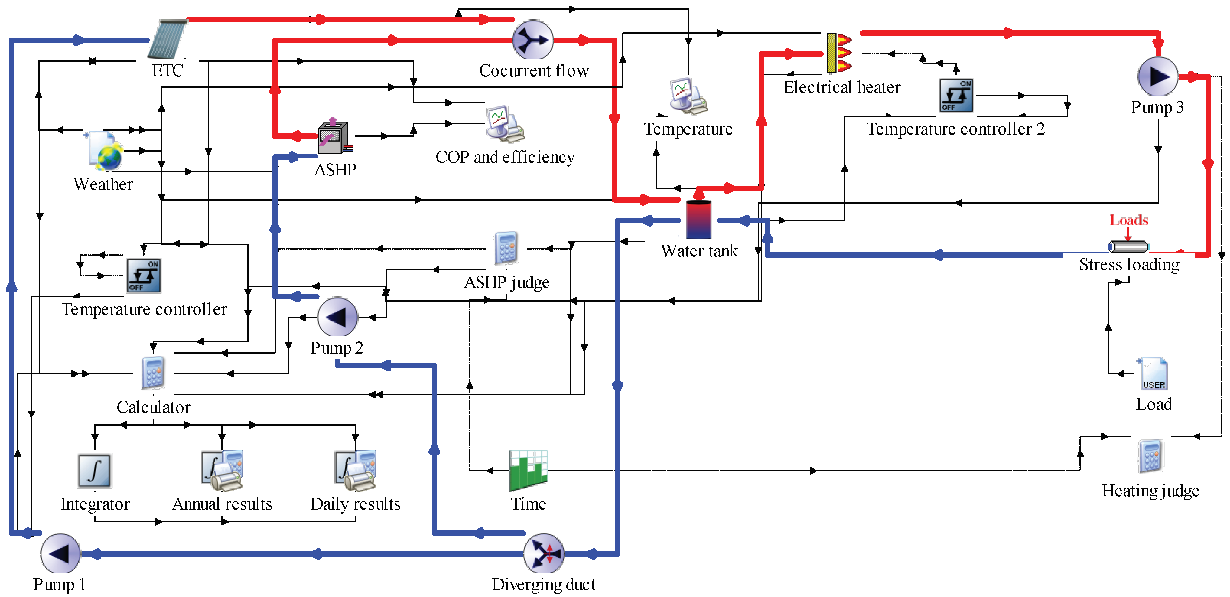
3.4. Heating System Model Establishment and Control Strategy

The meteorological files of typical meteorological years in Xi’an were selected, and the SASHPHS with and without phase-change heat storage was modeled using TRNSYS 18 software. The simulation model is shown in Figure 7 and Figure 8. The blue lines in Figure 7 and Figure 8 indicate the cold water piping in the system, and the red lines indicate the hot water piping. The ETC and ASHP heated the cold water, and the heated water then flowed into the tank. The hot water in the tank provided heat to the heating building before flowing back into the tank. The heating period was considered 15 November to 15 March of the following year (7632~10,536 h), and the time step was set to 0.05. The system ran from 8:00 to 20:00 every day. Because the weather was very sunny on the 26th of February (10,104~10,128 h), it was chosen as a typical day for heating. January (8760~9504 h) was selected as the typical heating month.
The temperature difference between the inlet and outlet of the ETC was judged by the temperature difference controller. Pump 1 started when the temperature difference was greater than 6 °C and stopped when the temperature difference was less than 3 °C. The heating system ran from 8:00 to 20:00 every day, so the output signal of the time-varying function was 0 for the rest of the time. The LT function in the calculator judged the outlet water temperature of the top layer of the water tank, and the INT function in the calculator was intended to integrate the judgment result of temperature and heating time. Then, the results of the INT function were output to the ASHP and pump 2 to achieve the control purposes. Temperature difference controller 2 determined the water supply temperature. When the temperature did not reach 40 °C, the auxiliary electric heating was turned on. The loop control of the heating side was realized by the time-varying function and the calculator, and the output of the time-varying function was judged by the calculator GT function. During the heating time, pump 3 opened and heating began.
Under the same weather and load conditions, the SASHPHS was operated separately with and without a phase-change heat storage system, and the results were compared and analyzed.

4. Analysis of Results

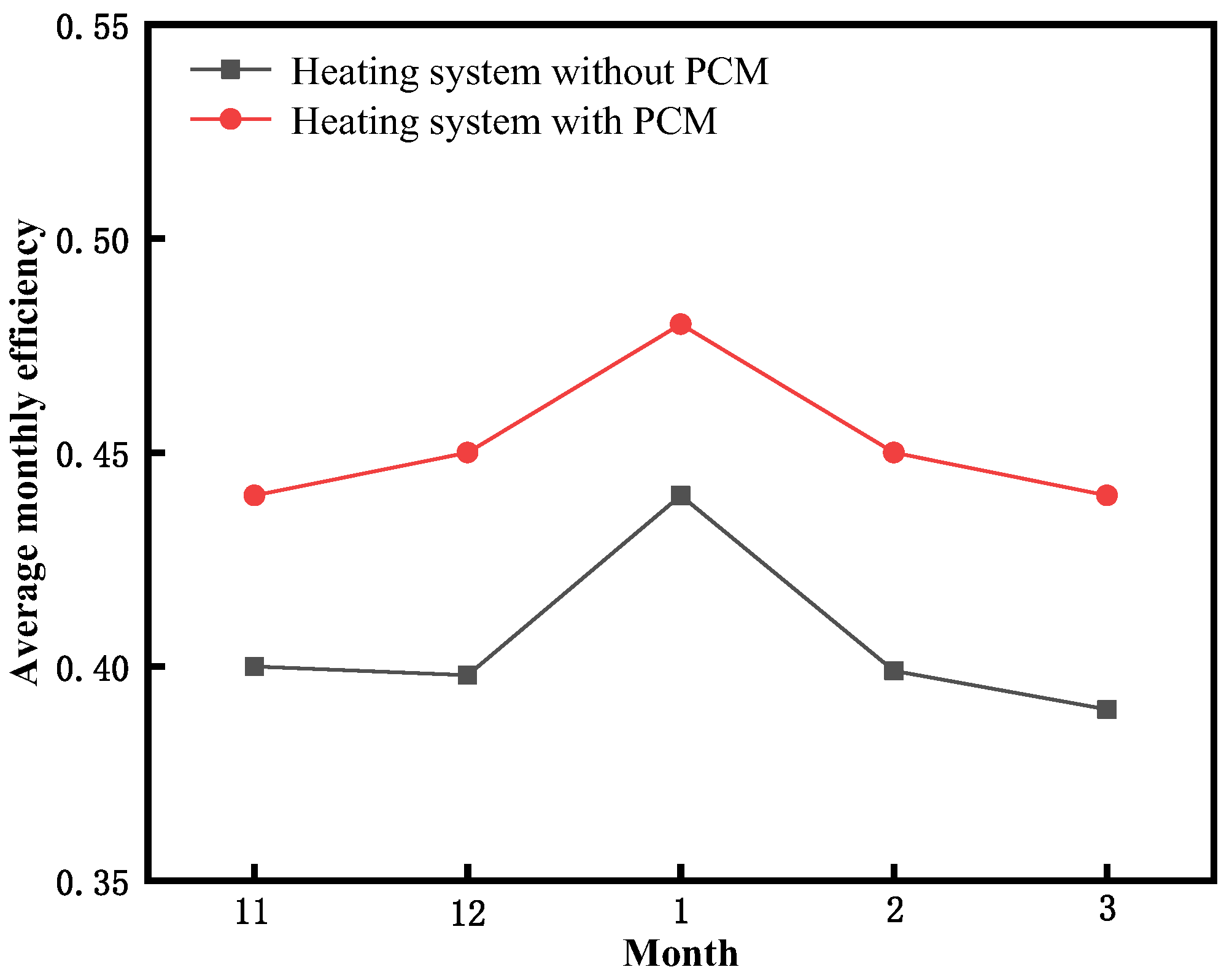
4.1. Collector Efficiency

The solar collector was an important part of the entire heating system and provided most of the heat for the entire system. Collector efficiency is a crucial index for evaluating the performance of a collector and can be defined as the ratio of the collector’s useful energy to the solar radiation received by all lighting areas of the collector. For the heating period, the monthly average heat collection efficiency of the SASHPHS with and without phase-change heat storage was compared. It can be seen from Figure 9 that the average monthly collection efficiency of the phase-change heat storage heating system was higher than that of the conventional SASHPHS. Because the phase-change water tank contained a phase-change material layer, excess heat was absorbed and stored. The outlet temperature of the water tank was decreased, and the temperature difference of the collector between the inlet and outlet was increased, which further increased the useful energy of the collector.
The amount of solar radiation absorbed by the collector was solely determined by its surface area and was independent of the presence of the phase-change material in the system. The total solar radiation received by the collector in the traditional heating system was the same as that in the phase-change system, and the useful energy of the collector in the phase-change system was higher than that in the traditional system. Consequently, compared to traditional systems, the thermal efficiency of the collector in this study’s phase-change heating system was higher. Additionally, it was found that during the heating period, the average efficiency of the SASHPHS with the PCM was 45.8%, which was 5.9% higher than that without the PCM. Furthermore, due to increased sunshine hours and larger solar radiation levels in January, this month exhibited a higher average thermal efficiency compared to other months.

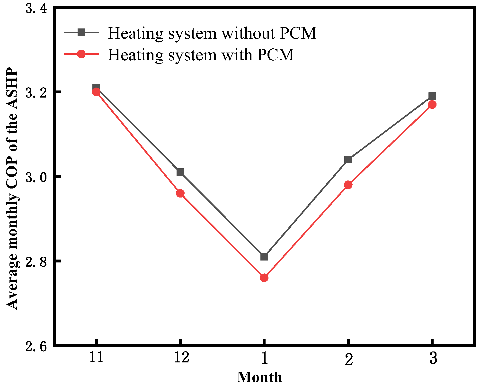
4.2. Performance of ASHP

In the solar air-source heat pump heating system, when the solar radiation was insufficient, the air-source heat pump started to heat the building. A comparison of the monthly average COP of the SASHP heating system with and without a PCM during the heating period is shown in Figure 10. It was clear that the COP change trend of the air-source heat pump in the two heating systems was the same during the heating period; both systems showed a trend of declining first and then rising. This trend was the same as the variation trend of the outdoor ambient temperature in Xi’an. The average COP of the ASHP was the lowest, which was caused by the low outdoor ambient temperature in Xi‘an in January. The lower the outdoor ambient temperature, the lower the air temperature of the ASHP inlet. The ASHP generated less heat in January for the same amount of electricity consumed. Therefore, the average COP of the ASHP was the lowest in January. It was also found that the average monthly COP of the ASHP in the phase-change heat storage system was slightly lower than that in the traditional heating system. Both of the systems with and without a PCM bear the same heat load; the useful energy of the ETC in the phase-change system was larger, and the auxiliary heating required by the system was less, so the heating capacity of the ASHP was less, and the COP was slightly lower. During the whole heating period, the average COP of the traditional system was 3.01, and the average COP of the phase-change system was 2.96, decreasing by 0.05.

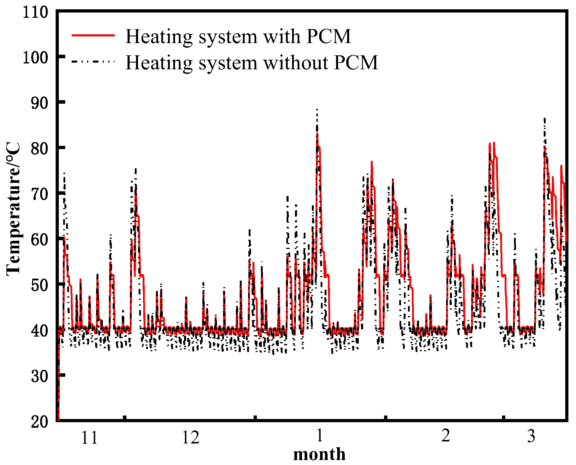
4.3. Phase-Change Water Tank

Putting a phase-change material into the water tank is the main way to combine the phase-change material with the water tank. Although more heat is stored in this way, when the phase-change material leaks, it will pollute the hot water to some extent. In this study, we proposed a novel method that involved laying a certain thickness of a phase-change material on the side wall of the water tank; this method not only overcame the aforementioned drawbacks but also enhanced heat transfer between the phase-change material and water by increasing their contact area. Figure 11 illustrates a comparison of outlet water temperature throughout the heating period for systems with and without a PCM. In the conventional system, there was a significant fluctuation in outlet temperature, which ranged from 34.85 °C to 88.89 °C during stable operation. On the other hand, in PCM-based systems, fluctuations were significantly reduced, with maximum and minimum outlet temperatures recorded at 83.58 °C and 38.25 °C, respectively, resulting in more stable water outlet conditions. The PCM worked in two ways: when heat was sufficient, excess heat was absorbed and stored; when heat was insufficient, the PCM released heat to heat the fluid. Heat was stored and released in a continuous cycle to achieve the incongruity of energy in time and space, and energy was used more efficiently. Therefore, when the temperature of the fluid in the water tank was higher than the melting temperature of the PCM, the heat in the water tank was absorbed, and the temperature of the hot water was reduced. When the fluid temperature in the water tank was lower than the melting temperature of the PCM, the PCM released heat for the heating of the fluid, making the water temperature rise. The minimum outlet temperature of the water tank was increased, and the electric energy consumed by the auxiliary heating of the system was also greatly decreased.
As shown in Figure 12, the changes in the outlet temperatures at the top of the tank in the heating systems with and without a PCM were analyzed on typical days. The results presented in Figure 12 show that the outlet water temperature of the ordinary water tank was higher than that of the phase-change water tank. The maximum effluent temperature of the ordinary water tank reached 71.32 °C at about 13:00~14:00. The peak of the outlet temperature in the phase-change heat storage was found to be 63.42 °C at 15:00. Between 8:00 and 14:00, the outlet temperature of the water tank in the SASHPHS without the PCM was higher than that of the system with the PCM, and the temperature rose more rapidly. This is attributed to the fact that part of the heat in the heating system with the PCM was absorbed and stored by the PCM, and the other part was used to heat water. However, in the system without the PCM, the total heat was absorbed by water, so the rise rate was faster. It was clear also that between 15:00 and 20:00, the exit temperature of both the phase-change tank and the traditional tank presented a downward trend, and the temperature of the traditional tank was lower than that of the phase-change water tank. The reason was that the release of heat stored in the PCM slowed the temperature change of the tank, and the rate of cooling of the tank temperature was also reduced. The temperature dropped faster in the common water tank than in the phase-change water tank, so the temperature difference between the two tanks gradually increased.
The heat storage and release of the PCM layer in the phase-change water tank can be obviously seen in Figure 13. It can be clearly seen from Figure 13a that the total heat storage of the phase-change material was greater than the total heat release in the typical month. When the outlet temperature of the water tank was higher than 53 °C during the day, the excess heat in the hot water was stored by the PCM. On cloudy days or at night, when the outlet temperature of the water tank was lower than 53 °C, the hot water absorbed the heat released by the PCM. It is also seen that the maximum heat storage in the phase-change tank was 19.21 kW, which occurred at noon in very sunny weather. The peak of the heat release from the phase-change thermal storage tank was 10.89 kW.
To further reflect the effectiveness of the system, heat storage and discharge analysis of the phase-change material was performed for the coldest day of the heating period. The coldest day outside during the heating period was 1st January. The heat storage and discharge of the PCM in the tank during working hours on that day are shown in Figure 13b. It can be seen that the maximum heat storage of the phase-change material was 0.69 kW, and the maximum heat release was 0.45 kW. On the coldest day, the PCM still distributed heat properly, even when there was less to distribute.

4.4. System Energy Consumption

When the outlet water temperature of the load side of the water tank in the phase-change heating system was lower than 40 °C, the auxiliary heating equipment was turned on until the hot water temperature reached 40 °C. The simulation results of the heating system with and without phase-change heat storage in the whole heating period are summarized in Table 3.
It can be seen from Table 3 that the PCM stored excess heat and released it at the right time, and the minimum temperature at the outlet of the tank was increased, thereby reducing the electric heating capacity by 169.55 kWh. In addition, under the same building load, the total heating capacity of the ASHP in the phase-change heating system was reduced by 810.82 kWh. Even if the COP of the ASHP was slightly reduced, the electric energy consumed by the ASHP was still decreased. The energy consumption of electric heating and the ASHP decreased, so the total energy consumption of the phase-change heating system was also reduced by 484.91 kWh. Therefore, compared with the conventional heating system, the SASHPHS based on phase-change heat storage made more effective use of solar energy and had the advantage of saving electricity.

5. Conclusions

In order to address the limitations of traditional solar air-source heat pump heating systems, such as insufficient solar utilization and high energy consumption, we proposed an enhanced phase-change storage solar air-source heat pump heating system. A numerical model was developed for the Xi’an region to analyze the system’s performance during the heating period, leading to the following conclusions:
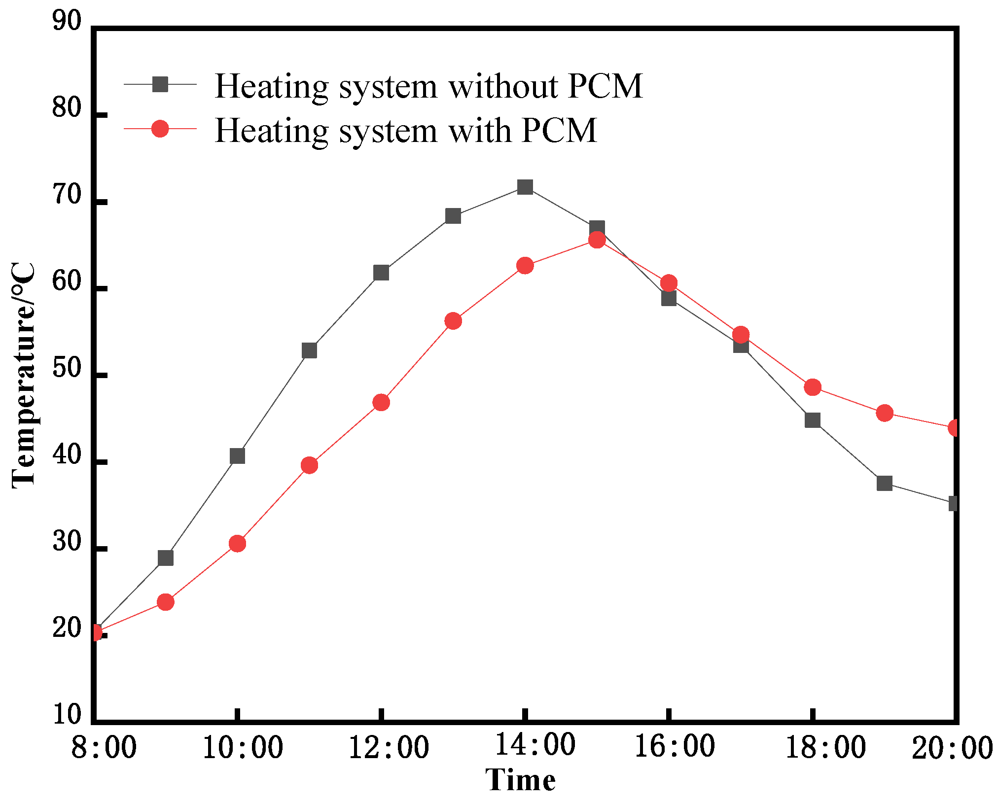
  • The incorporation of a PCM significantly enhanced the temperature difference between the inlet and outlet of the solar collector in the heating system, thereby further augmenting its useful energy output. As a result, compared to the heating system without the PCM, the phase-change heating system exhibited an average heat collection efficiency of 45.8% throughout the entire heating period—an improvement of 5.9%. This demonstrated a more comprehensive and effective utilization of solar energy. Under identical load conditions, the phase-change system reduced the heating capacity requirement by 810.82 kWh while slightly decreasing the COP of the ASHP.
  • Compared with the traditional system, the improved phase-change heating system was more rational in the distribution of heat. The existence of the PCM alleviated the temperature drop of the auxiliary heating measurement, so the electric heating capacity of 169.55 kWh was saved. The phase-change heat storage system reduced the total energy consumption by 484.91 kWh during the whole heating operation, which had a great energy-saving advantage.
  • The addition of phase-change heat storage technology offered a more stable heat source to the PCM-based heating system. Additionally, the manufacturing of the phase-change water tank was relatively simple, and the processing technology of the water tank was fairly mature. So, the phase-change heating system in this paper could be well developed.

Author Contributions

Writing—original draft preparation, P.L.; writing—review and editing, J.Z. and J.C. All authors have read and agreed to the published version of the manuscript.

Funding

This research was supported by The National Natural Science Foundation of China (Grant No. 51974225).

Institutional Review Board Statement

Not applicable.

Informed Consent Statement

Written informed consent has been obtained from the patient(s) to publish this paper.

Data Availability Statement

At the request of the funder, we are sorry that the data for this article is unavailable due to privacy or ethical restrictions.

Acknowledgments

Thank you to everyone who helped with this article.

Conflicts of Interest

The authors declare no conflict of interest. The funders had no role in the design of the study; in the collection, analyses, or interpretation of data; in the writing of the manuscript; or in the decision to publish the results.

Nomenclature

SASHPHSsolar air-source heat pump heating system
SCsolar collector
SAHPair-source heat pump
COPcoefficient of performance
PCMphase-change material
MAmyristic acid
EGexpanded graphite
ETCevacuated tube collector
Quthe useful thermal energy of the fluid
ηefficiency of the solar collector
Qthe heat storage of the phase-change water tank
Qdthe useful thermal energy of the fluid during the day
Ttankinitial water temperature of the tank
TASHP-OUToutlet water temperature of the air-source heat pump
TASHP-INinlet water temperature of the air-source heat pump

References

  1. Jiang, Y. Annual Report on China Building Energy Efficiency; China Architecture and Building Press: Beijing, China, 2011. [Google Scholar]
  2. Ma, H.T.; Du, N.; Yu, S.J. Analysis of typical public building energy consumption in northern China. Energy Build. 2017, 136, 139–150. [Google Scholar] [CrossRef]
  3. Wang, F.L.; Liu, X.; Jiang, B.H.; Zhuo, H.; Chen, W.; Chen, Y.; Li, X. Low-loading Pt nanoparticles combined with the atomically dispersed FeN sites supported by Fe-N-C for improved activity and stability towards oxygen reduction reaction/hydrogen evolution reaction in acid and alkaline media4SA. J. Colloid Interface Sci. 2023, 635, 514–523. [Google Scholar] [CrossRef] [PubMed]
  4. Li, Q.C.; Zhao, D.F.; Yin, J.K.; Zhou, X.; Li, Y.; Chi, P.; Han, Y.; Ansari, U.; Cheng, Y. Sediment Instability Caused by Gas Production from Hydrate-bearing Sediment in Northern South China Sea by Horizontal Wellbore: Evolution and Mechanism. Nat. Resour. Res. 2023, 8, 1–26. [Google Scholar] [CrossRef]
  5. Aytac, A.; Seckin, K. Investigation of the effect of decomposition methods on wind speed forecasting model performance defined by deep learning algorithm. Eur. J. Sci. Technol. 2020, 20, 844–853. [Google Scholar]
  6. Mekhilef, S.; Saidur, R.; Safari, A. A review on solar energy use in industries. Renew. Sustain. Energy Rev. 2011, 15, 1777–1790. [Google Scholar] [CrossRef]
  7. Hawlader, M.N.A.; Chou, S.K.; Ullah, M.Z. The performance of a solar assisted heat pump water heating system. Appl. Therm. Eng. 2003, 21, 1049–1065. [Google Scholar] [CrossRef]
  8. Huang, B.J.; Lee, C.P. Long-term performance of solar-assisted heat pump water heater. Renew. Energy 2004, 29, 633–639. [Google Scholar] [CrossRef]
  9. Kuang, Y.H.; Sumathy, K.; Wang, R.Z. Study on a direct-expansion solar-assisted heat pump water heating system. Int. J. Energy Res. 2003, 27, 531–548. [Google Scholar] [CrossRef]
  10. Zhan, H.; Wu, R.H.; Yu, H. Load analysis and area optimization of Solar heat pump system for daytime heating. J. Eng. Therm. Energy Power 2022, 37, 124–130. [Google Scholar]
  11. Zeng, N.H.; Yuan, Y.P.; Sun, L.L. Optimization on air source heat pump assisted solar water heating system based on TRNSYS. Acta Energ. Sol. Sin. 2018, 39, 1245–1254. [Google Scholar]
  12. Wang, H.W.; Zhu, B.; Wu, D.M. Research on multi-regional applicability of solar energy-assisted air source heat pump system. Therm. Power Gener. 2022, 51, 18–26. [Google Scholar]
  13. Guo, C.M.; Xu, W.L.; Wang, Y. Experimental research on domestic hot water for solar energy-air source heat pump composite system in Guangdong. Therm. Sci. Technol. 2020, 19, 177–184. [Google Scholar]
  14. Sterling, S.J.; Collins, M.R. Feasibility analysis of an indirect heat pump assisted-solar domestic hot water system. Appl. Energy 2012, 93, 11–17. [Google Scholar] [CrossRef]
  15. Dikici, A.; Akbulut, A. Performance characteristics and energy-exergy analysis of solar-assisted heat pump system. Build. Environ. 2008, 43, 1961–1972. [Google Scholar] [CrossRef]
  16. Sun, Y.T.; Jiang, L.L.; Fan, W.Y. Research of solar air source heat pump system based on phase change energy storage. Renew. Energy Resour. 2021, 39, 169–174. [Google Scholar]
  17. Yan, S.Y.; Wang, Q.; Gao, S.J. Optimization of air source heat pump-solar hybrid heating system with increased heat storage. Renew. Energy Resour. 2021, 39, 754–759. [Google Scholar]
  18. Qu, S.L.; Ma, F.; Jia, R. System design and energy performance of a solar heat pump heating system with dual-tank latent heat storage. Energy Build. 2015, 105, 294–301. [Google Scholar] [CrossRef]
  19. Zhao, M.; Gu, Z.L.; Kang, W.B. Experimental investigation and feasibility analysis on a capillary radiant heating system based on solar and air source heat pump dual heat source. Appl. Energy 2016, 185, 2094–2105. [Google Scholar] [CrossRef]
  20. Zhu, H.Z.; Guo, B.; Geng, W.Z. Simulation of an improved solar absorption refrigeration system with phase change materials. Energy Rep. 2022, 8, 3671–3679. [Google Scholar] [CrossRef]
  21. Abdelsalam, M.Y.; Teamah, H.M.; Lightstone, M.F. Hybrid thermal energy storage with phase change materials for solar domestic hot water applications: Direct versus indirect heat exchange systems. Renew. Energy 2020, 147, 77–88. [Google Scholar] [CrossRef]
  22. Zhang, N.; Yuan, Y.P.; Wang, X.; Cao, X.; Yang, X.; Hu, S. Preparation and characterization of lauric-myristic-palmitic acid ternary eutectic mixtures/expanded graphite composite phase change material for thermal energy storage. Chem. Eng. J. 2013, 231, 214–219. [Google Scholar] [CrossRef]
  23. Yang, X.J.; Yuan, Y.P.; Zhang, N.; Cao, X.; Liu, C. Preparation and properties of myristic-palmitic-stearic acid/expanded graphite composites as phase change materials for energy storage. Sol. Energy 2014, 99, 259–266. [Google Scholar] [CrossRef]
  24. Cao, X.L.; Yuan, Y.P.; Wang, X. Preparation and thermal property of myristic acid / expanded graphite composite as phase change material. Acta Energ. Sol. Sin. 2014, 35, 1493–1498. [Google Scholar]
  25. Huang, P.; Ding, Y.M.; Hu, T.; Zhang, J.; Wang, X. Study on preparation and properties of myristic-stearic acid /modified fly ash composite phase change energy storage materials. J. Funct. Mater. 2017, 48, 5154–5158. [Google Scholar]
  26. Wang, X.; Yuan, Y.P.; Deng, Z.H. Operating characteristic of latent heat storage water tank. Acta Energ. Sol. Sin. 2014, 35, 670–676. [Google Scholar]
  27. Han, K.Y.; Liu, Z.Q.; Dong, M. Analysis of influence of water temperature and value of heat storage tank on the performance of solar heat collecting system. J. Therm. Sci. Technol. 2022, 21, 373–382. [Google Scholar]
  28. Jin, G.; Chen, Z.H.; Guo, S.P. Heating Experimental study of solar air source heat pump system in severe cold areas. Acta Energ. Sol. Sin. 2021, 42, 251–257. [Google Scholar]
  29. Man, X.X. Optimization of Solar Heating System with Phase Change Heat Storage in Cold Regions. Master’s Thesis, Liaoning University of Technology, Jinzhou, China, 2021. [Google Scholar]
Figure 1. Schematic diagram of the phase-change heating system.
Sustainability 15 15684 g001
Figure 2. Phase-change water tank structure diagram.
Sustainability 15 15684 g002
Figure 3. Comparison of day useful energy values for the collector [27].
Sustainability 15 15684 g003
Figure 4. Comparison of experimental and simulated parameters of ASHP: (a) inlet and outlet water temperature of ASHP; (b) COP of ASHP [28].
Sustainability 15 15684 g004
Figure 5. Temperature comparison of PCM during heat storage and release in phase-change water tank: (a) temperature comparison in water tank heat storage; (b) temperature comparison in water tank heat release [29].
Sustainability 15 15684 g005
Figure 6. Hourly heat load of the building during the heating period.
Sustainability 15 15684 g006
Figure 7. Model of solar air-source heat pump heating system based on phase-change heat storage.
Sustainability 15 15684 g007
Figure 8. Model of conventional solar air-source heat pump heating system.
Sustainability 15 15684 g008
Figure 9. Comparison of monthly average heat collection efficiency of different systems.
Sustainability 15 15684 g009
Figure 10. Comparison of monthly average COP of ASHP in different systems.
Sustainability 15 15684 g010
Figure 11. Comparison of outlet water temperature on the load side of the tank during the heating period.
Sustainability 15 15684 g011
Figure 12. Comparison of outlet water temperature on the load side of the tank on the typical day.
Sustainability 15 15684 g012
Figure 13. Heat storage and release of phase-change water tank: (a) heat storage and release in the typical month; (b) heat storage and release on the coldest day.
Sustainability 15 15684 g013
Table 1. Specific parameters of the PCM.
ParametersNumerical Value
Thermal conductivity0.22 W/(m·°C)
Phase-change temperature53 °C
Latent heat of phase change191.75 kJ/kg
Liquid specific heat capacity2.265 kJ/(kg·°C)
Solid specific heat capacity2.218 kJ/(kg·°C)
Density862 kg/m3
Table 2. Parameters of the main components of the phase-change heating system.
ObjectType NumberParameters
Solar collector71Area: 56 m2;
Slope: 25°.
Air-source heat pump941Rated heating capacity: 12.5 kW;
Water tank158Volume: 3 m3.
Edge loss coefficient: 1000 W/(m2·°C);
Top loss coefficient: 0.6 W/(m2·°C);
Bottom loss coefficient: 0.6 W/(m2·°C).
Phase-change layer1270aThickness: 0.12 m;
Density of PCM: 862 kg/m3;
Phase-change temperature: 53 °C;
Latent heat of PCM: 191.75 J/g.
Table 3. Heat and energy consumption statistics during heating period.
SystemUseful
Energy of ETC (kWh)
Total Solar
Radiation (kWh)
Heating
Capacity of ASHP (kWh)
Electric
Heating
Capacity (kWh)
Energy
Consumption (kWh)
Heating system without PCM3955.7310,149.405792.54288.862749.80
Heating System with PCM4648.0210,149.404981.72119.312264.89
Disclaimer/Publisher’s Note: The statements, opinions and data contained in all publications are solely those of the individual author(s) and contributor(s) and not of MDPI and/or the editor(s). MDPI and/or the editor(s) disclaim responsibility for any injury to people or property resulting from any ideas, methods, instructions or products referred to in the content.

