Article

A High Speed MPPT Control Utilizing a Hybrid PSO-PID Controller under Partially Shaded Photovoltaic Battery Chargers

1
School of Electrical Engineering, Southeast University, Nanjing 210096, China
2
School of Automation, China University of Geoscience, Wuhan 430074, China
3
LACoSERE Laboratory, Amar Telidji University, Laghouat, Algeria
4
Department of Electrical Power and Machines, Faculty of Engineering, Alexandria University, Alexandria 21544, Egypt
5
Department of Electrical Engineering, Jubail Industrial College, Jubail 31961, Saudi Arabia
*
Authors to whom correspondence should be addressed.
Sustainability 2023, 15(4), 3578; https://doi.org/10.3390/su15043578
Submission received: 21 January 2023 / Revised: 26 January 2023 / Accepted: 29 January 2023 / Published: 15 February 2023
(This article belongs to the Special Issue Intelligence and Sustainability in Electrical Engineering)

Abstract

:
Improving photovoltaic systems in terms of temporal responsiveness, lowering steady-state ripples, high efficiency, low complexity, and decreased tracking time under various circumstances is becoming increasingly important. A particle-swarm optimizer (PSO) is frequently used for maximum power-point tracking (MPPT) of photovoltaic (PV) energy systems. However, during partial-shadowing circumstances (PSCs), this technique has three major drawbacks. The first problem is that it slowly converges toward the maximum power point (MPP). The second issue is that the PSO is a time-invariant optimizer; therefore, when there is a time-variable shadow pattern (SP), it adheres to the first global peak instead of following the dynamic global peak (GP). The third problem is the high oscillation around the steady state. Therefore, this article proposes a hybrid PSO-PID algorithm for solving the PSO’s three challenges described above and improving the PV system’s performance under uniform irradiance and PSCs. The PID is designed to work with the PSO algorithm to observe the maximum voltage that is calculated by subtracting from the output voltage of the DC-DC boost converter and sending the variation to a PID controller, which reduces the error percentage obtained by conventional PSO and increases system efficiency by providing the precise converter-duty cycle value. The proposed hybrid PSO-PID approach is compared with a conventional PSO and bat algorithms (BAs) to show its superiority, which has the highest tracking efficiency (99.97%), the lowest power ripples (5.9 W), and the fastest response time (0.002 s). The three aforementioned issues can be successfully solved using the hybrid PSO-PID technique; it also offers good performance with shorter times and faster convergence to the dynamic GP. The results show that the developed PID is useful in enhancing the conventional PSO algorithm and solar-system performance.

1. Introduction

Photovoltaic (PV) energy is one of the cleanest, most reliable, and most promising types of renewable energy because of its environmentally friendly nature, unlimited supply, ease of maintenance, and peaceful operation [1,2]. However, the most problematic element of photovoltaic systems is that their electrical behavior is nonlinear and changes in reaction to external conditions such as the amount of sunlight and temperature. The management of PV systems requires a certain strategy to obtain the MPP of the photovoltaic system. Several MPP tracking (MPPT) technologies have been established recently to increase the efficiency of solar systems. There is a consensus that when several peaks are identified in the power–voltage (P-V) curve under partial-shading conditions (PSCs), it is important to determine the global maximum power point (GMPP) [2].
The MPP can be extracted from PV sources using a number of different MPPT techniques. These methods can be roughly divided into the following three categories: (1) conventional, (2) soft computing, and (3) hybrid MPPT methods. The traditional methods include incremental conductance (INC) [3], hill climbing (HC) [4], and perturbation and observation (P&O) [5]. These conventional methods are ineffective during PSCs because of the multiple-peak power phenomena present in the power–voltage or current–voltage (P-V or I-V) characteristic curves. However, they are effective when all PV modules are subjected to the same environmental circumstances (uniform irradiance). It is significant that over the past several years numerous scholars have raised awareness of the aforementioned issues and attempted to improve MPPT controller performance under PSCs. Therefore, they used a number of smart, elegant soft-computing metaheuristic-optimization techniques instead of conventional methods, such as differential evolution-based MPPT (DE) [6], the flower-pollination algorithm (FPA) [7], the salp-swarm algorithm (SSA) [8], ant-colony optimization (ACO) [9], artificial bee colony (ABC) [10], the cuckoo-search algorithm (CSA) [11], the firefly algorithm (FFA) [12], the whale-optimization algorithm (WOA) [13], dragonfly optimization (DFO) [14], the salp-swarm algorithm (SSA) [15], particle-swarm optimization (PSO) [16], the bat algorithm (BA) [17], gray-wolf optimization (GWO) [18], and moth–flame optimization (MFO) [19].
Furthermore, artificial intelligence-based MPPT techniques have been created to mitigate the impacts of PSCs, including neural networks (NN) [20], deep learning (DL) [21], and fuzzy-logic controls (FLC) [18]. Soft-computing techniques can be used to handle the partial-shading phenomena. However, the main drawback of the latter is its high computational complexity. Hybrid methods, which combine two or more MPPT techniques, have recently been established to improve MPPT performance and efficiency [22]. According to the literature, the GMPP may be successfully monitored utilizing hybrid methods under various PSCs. However, the advantages of powerful processors enable all of the soft-computing-based techniques discussed above to accurately assess the GMPP with the conventional methods. Therefore, they are costly for PV applications. MPPT approaches such as metaheuristic algorithms combined with conventional methods must be used to solve the above challenges. The most-used hybrid algorithms are PSO-P&O [23,24,25,26,27,28,29], PSO-HC [30], PSO-PI [31], GWO-P&O [32], WOA-P&O [33], ABC-IMP&O [34], ACO-P&O [35], FFA-INC [36], and ANN-P&O [37].
Several studies [22,38,39,40,41] claimed that the original PSO approach could monitor the GP in general, but they ignored the fact that the SP varies with time and that therefore the GP’s location and value vary as well. In addition, the original PSO has visible oscillations around the steady state and a sluggish convergence speed. As a result, PSO can monitor the GP with unwanted oscillation around the steady state and sluggish convergence speed under the same SP. Shi et al. [38] developed a PSO paired with INC to lessen the oscillations at steady state that occurs when a PSO is employed individually to address the aforementioned disadvantages of the original PSO. The PSO looks for the GP region, and INC then monitors the GP inside the same SP. In addition, the undesired steady-state oscillations are reduced; however, the track time is very long since they assumed that the SP is constant, which makes it impossible to change the GP. Lian et al. [24] presented the P&O-PSO technique to capture the dynamic GP during the temporal-variation SP. Once P&O obtains the nearest LP, the PSO is used to catch the dynamic GP. The role of the PSO, which is still present along with apparent oscillations close to steady state, is still unclear when the GP is at the beginning, where P&O may follow the initial peak whether it is LP or GP. In [18], the authors proposed a hybrid PSO with fuzzy-logic control (PSO-FLC) based on PSO particle distribution. This approach can resolve the PSO issue using a time-invariant optimization methodology that adheres to the initial dynamic GP that appears at the start of unfavorable steady-state oscillations instead of following the dynamic GP under time-variant shading patterns. However, it has one drawback: It takes a long time to catch the GP. Table 1 compares the most important variables in the previously provided studies with those in the current effort to provide a clearer overview of the literature section.
According to the aforementioned research evaluation, some drawbacks can be identified as follows:
  • A conventional PSO may be able to monitor the GP under a time-invariant shading pattern with unwanted volatility at a steady state. Although it takes longer to catch up to the GP, it is impossible to follow the dynamic GP under time-variation SPs and remains at the initial GP.
  • Previous studies have tracked the GP under PSC; however, they have slow convergence to the GP and high oscillation around the GP, and the tracking time is very long.
  • Some of these MPPT methods work successfully under uniform and PSC conditions. However, the use of the algorithm individually has some drawbacks and limitations.
To mitigate these issues, a digital-feedback PID controller with a PSO algorithm-based MPPT approach (PSO-PID) is proposed in this paper to achieve the maximum efficiency of the PV system. The major contributions of this paper can be summarized as follows:
  • A hybrid MPPT approach based on the PSO-PID method is proposed to combine the ability of the PSO to ensure GP operation with the convergence speed of the PID controller. The PV arrays’ accuracy and efficacy are improved by hybrid MPPT techniques under unpredictable and changing environmental conditions.
  • The hybridization (PSO-PID) MPPT algorithm for PV systems under normal and PSC conditions provides high efficiency, quick convergence, zero oscillation around the steady state, and low complexity.
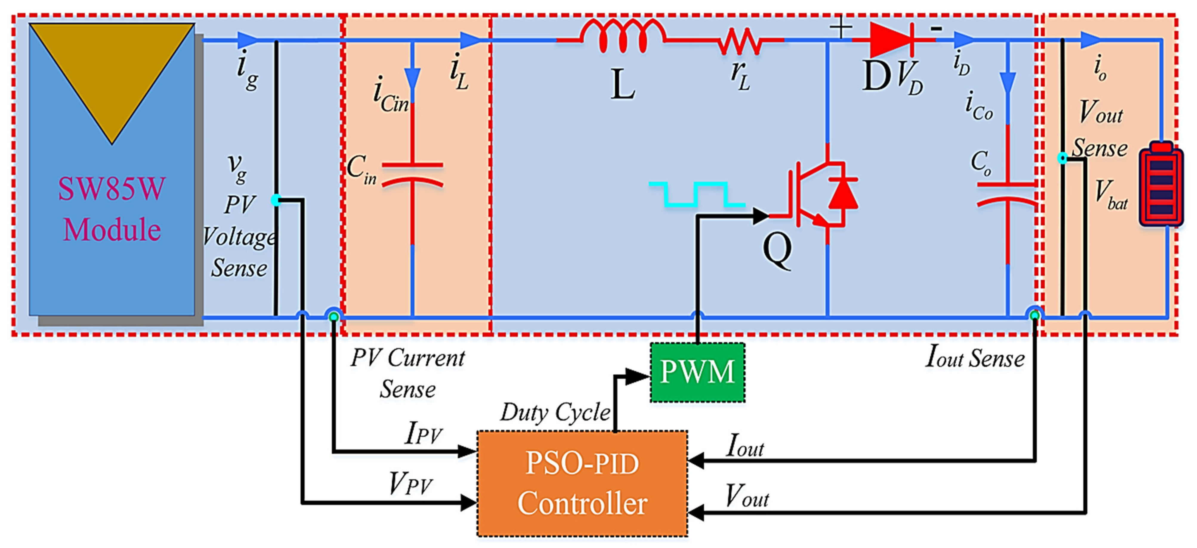
  • In order to increase the system response time and shorten the tracking process, the robust design of the PID controller with the PSO algorithm is adopted for boost converter in this article. The controller uses the reference voltage provided by the MPPT algorithm as an input to compute the matching duty cycle. When charging batteries, for example, the regulated voltage is employed. The comparator creates an error signal by comparing the output voltage to the reference voltage, and then it sends that error signal to the PID controller. The PWM generator produces the PWM signals for the power module after being sent to the PID controller, which is utilized for regulating the voltage signal.
  • The performance of the combined PSO-PID algorithm is examined and compared with conventional PSO and BA-MPPT methods for validation purposes.
This paper is organized as follows. Section 2 presents the description of the considered system, and Section 3 presents the modeling of the photovoltaic system under PSC. Section 4 contains the proposal for the PSO-PID controller, and the presentation of the simulation results is covered in Section 5. Finally, the conclusion is provided in Section 6.

2. Description of the Considered System

2.1. Modeling and Description of PV Systems

Figure 1 shows the studied photovoltaic system, which consists of a PV generator, a boost converter, a suggested controller, and a battery bank [50].

2.2. Modeling of the PV System

A model is required to regulate the system using various MPPT strategies.

2.2.1. The Model of PV Panel

The literature offers several electric models for modeling PV panels. The materials used in the PV cells that make up the panel determine which is the best option. In this instance, a multi-crystalline silicon PV panel was used, and a five-parameter model with a single diode was employed. The comparable electrical circuit for a PV panel made up of Ns series cells and Np parallel strings is shown in Figure 2. Equation (1) provides the PV panel’s mathematical expression [51].
i g = i P h g i s g [ e q ( v g R s g i g ) N s A K T j 1 ] v g R s g i g R P g
where i g = N p i P h , i P h g = N p i P h , v g = N s v , R s g = ( N s / N P ) R s and R P g = ( N s / N P ) R P .
Obviously, the PV equation is nonlinear. A linearized model for the photovoltaic system is necessary to make system modeling easier.

2.2.2. Modeling the PV Panel’s Linearization

Non-linear Equation (1) describes the PV output characteristic. Through the linearization procedure, the partial derivative i g / v g should provide the small-signal model.
The dynamic conductance can be calculated by partial differentiation and stated as Equation (2) using the analogous PV panel circuit shown in Figure 2 and the corresponding equation. RPV is the dynamic resistance and is shown in Figure 3.
G P V ( v g , i g ) = i g v g = 1 R P V
When the output features of photovoltaics are linearized at the MPP area, it results in Equation (3):
G P V ( V M P P , I M P P ) = i s g q N s A K T j e q ( V M P P + R s g I M P P ) N s A K T j 1 R P g
where GPV is the linearization of the PV output characteristic, q is the electron charge (1.6 × 10 −19 C), Ns is the number of solar cells connected in series, Np is the number of solar cells connected in parallel, Io is the reverse-saturation current at typical test conditions, T is the degree of absolute temperature, A is the value of the diode-ideality constant, and K is the quantity of the Boltzmann constant (1.38 × 10 −23 J/K). Figure 4 shows the PV generator’s equivalent circuit for the MPP area.
The PV system then takes the position of the photovoltaics panel with its linear equivalent circuit, as seen in Figure 5.

2.2.3. Transfer Function for PV Systems

The switch’s on/off states during a single switching cycle can be used to derive the following system equations:
On-state dynamics of Q:
d i L d t v g r L i L
C i n d v g d t i g i L V e q v g R e q i L
Off-state dynamics of Q:
d i L d t v g r L i L ( V d V b a t )
C i n d v g d t = i g i L = V e q v g R e q i L
The system equations, averaged over one switching cycle, are as follows:
L d i L d t = v g r L i L ( V d + V b a t ) d
C i n d v g d t = V e q v g R e q i L
where the control variable is d = 1 d .
The state-space form of the tiny signal model is provided as follows:
d d t ( i ˜ L v ˜ g ) = ( r L L 1 L 1 C i n 1 R P V C i n ) ( i ˜ L v ˜ g ) + ( V d + V b a t L 0 ) d
y ˜ = ( 0 1 ) ( i ˜ L v ˜ g )
Using the Laplace transformation, the relationship between the control variable d ˜ and the small-signal voltage v ˜ g is given as Equation (12).
G v d ( S ) = v ˜ g d ˜ = K v d s 2 ξ v d ω v d ω v d 2
where
K v d = ( V d V b a t ) C i n
ξ v d = r L R P V C i n L 2 L R P V C i n ω v d
ω v d = R P V r L R P V C i n
Equation (16) may be used to calculate the PV system’s settling time without employing PV voltage feedback.
T s t _ o p = L n ( 0.02 1 ξ v d ) ξ v d ω v d
This value is crucial since it tells us how long we should wait before noticing the effects of a duty-cycle adjustment.
If the duty cycle is considered using the MPPT technique directly, the system settling time will be utilized to calculate the minimal-perturbation time, which is the reaction of PPV to an alteration in the duty cycle. In order for the MPPT method to accept fresh measurements of a new power, the minimum time that must elapse each time must be larger than or equal to the system settling time   T M P P T T s t _ o p . As a result, the MPPT output will be updated at a frequency of   f M P P T 1 / T s t _ o p [52].

3. Modeling of the Photovoltaic System under PSC

The PV array may be connected in series in various applications to raise the output voltage of the system. PV-panel parallel configurations are utilized to boost the output current of the system. Furthermore, to deliver the required voltage and current, the PV array can combine series and parallel connections. Three PV panels were linked in series and exposed to partial shading, as shown in Figure 6.
Partial shadowing caused by sunlight interference from nearby buildings or trees substantially impairs photovoltaic (PV) power systems. This affects the real output yield and completely undermines the lifetime of PV modules. The hotspot effect brought on by partial shading is often reduced through connection of a bypass diode in parallel to every PV module. The I-V and P-V curve of PV modules or strings, however, will exhibit many peaks rather than a single peak under partial-shading conditions, as shown in Figure 7. The highest one is a global maximum power point (GMPP) and the others are local maximum power points (LMPPs). GMPPs cannot be identified using typical MPPT methods since they are built to follow a single peak, and they may become caught around the LMPP. To attain the greatest power production under different PSCs, solar systems must thus use global maximum power-point tracking (GMPPT) algorithms.
The modeling of the proposed photovoltaic system, which includes both the power and control circuits, is shown in Figure 6. The PV array, boost converter, and battery bank as a load represent the power circuit of the PV system. The control circuit, on the other hand, contains the PSO-PID-based MPPT. Time-variable radiations, or PSCs, are used with three dissimilar GP values and places. The time variation of the shading patterns is chosen to ensure that there are three accessible GP scenes (GP at the beginning, middle, and end), as shown in Figure 7. To examine the output response of the combined PSO-PID to track the dynamic global peak with and without spreading the particles, a time variant of the shading patterns is employed to produce a GP in dissimilar positions on the P-V features. The goal of the PSO-PID is to combine the benefits of both the PSO and the PID. When the shadow pattern changes with time, the PSO can obtain the dynamic GP, but the PID cannot. On the other hand, the PID operates on a conditional basis to soften the GP observed by the PSO, as stated in the next section. Furthermore, it prevents the oscillations that occur when the PSO is applied alone near steady state. For the MPP tracking approach, a simulation time of 0.03 s was used. Therefore, the converter’s duty cycle was adjusted every 0.03 s.

4. Hybrid PSO-PID Technique

The behavior of swarms is used to represent particle-swarm optimization (PSO). Each particle in the algorithm is drawn to the global best position Gbest and the personal best position Pbest, but also has a tendency to wander randomly.
Let x i t and v i t represent the present position and velocity vectors for particle i, respectively. v i t + 1 can be obtained as:
v i t + 1 = v i t + α ε 1 ( G b e s t x i t ) + β ε 2 ( P b e s t x i t )
where ε1 and ε2 are the random values, which are between zero and one [0–1], and α and β are the acceleration constants or learning parameters. Then, the position of the following particles is determined as:
x i t + 1 = x i t + v i t + 1
There are several extensions to the conventional PSO method. The most notable enhancement is the inclusion of an inertia constant θ in Equation (17); therefore, v i t is substituted by θ v i t . Consequently, Equation (17) is adjusted as:
v i t + 1 = θ v i t + α ε 1 ( G b e s t x i t ) + β ε 2 ( P b e s t x i t )
This is comparable to injecting a fictitious mass to slow down the motion of the particles, and as a result, the algorithm converges more quickly. This method may be used to calculate the MPP of a PV system that has many peaks in its P–V features. This is achieved by using the following formula to define the particle position as the reference voltage V.
x i t = [ V 1 t , V 2 t V 3 t . , V n t ]
where n is the number of particles determined by the size of the array. The purpose is to increase the amount of energy generated by the PV array. To identify the global peak, the PSO algorithm is implemented as follows.
  • The particle positions are initialized at 20%, 50%, and 80% of Voc. The quantities, α, β, and θ are initialized throughout the algorithm. The best velocity vector Gbest and individual best Pbest values are initialized to zero.
  • The converter’s duty cycle is calculated for each particle position using Equation (21) and the resulting pulse is sent to the converter switch one at a time.
D = 1 V r e f V b a t
3.
The panel voltage VPV and current IPV are recorded after a delay, and the power for each particle position is computed using the formula PPV = VPV × IPV.
4.
The location of the particle where the power PPV is greatest is recognized as the optimal position of the particle.
5.
The global best is calculated as the position with the highest PPV among the personal best.
6.
Then Equation (17) is used to determine the velocity vector, and Equation (18) is used to update the position of the particle.
7.
The convergence condition is investigated. When all the values in the velocity vector are less than a tolerance limit or when the maximum number of iterations is reached, the algorithm is called convergence. If the convergence requirements are met, the global optimal value is generated. Otherwise, for the new position of the particles, steps 2–7 are repeated.
The algorithm’s primary goal in MPPT applications is to improve the PV system’s output power. Furthermore, the particle positions define the reference voltage of the photovoltaic array (Vref). In the meantime, the velocity is described as a slight deviation from or modification of the reference voltage (Vref). Similarly, Pbest designates the closest voltage value of each particle to the GP, whereas Gbest indicates the voltage value that generates the maximum power. As a result, particles are moved from their previous locations to the GP. The approach (Figure 8) does, however, show how many iterations are required for each particle to reach GP. Despite being the fastest ECA technique, the PSO algorithm has a lengthy convergence time. A hybrid PSO-PID MPPT technique is presented in Figure 8 to improve the system’s dynamic responsiveness.
The PSO and PID are combined in the proposed PSO-PID approach in this article. The goal of this strategy is to combine the benefits of these two strategies while avoiding their drawbacks. The PSO is effective and has the fastest convergence speed in capturing the GP of photovoltaic panels; however, it has minimal fluctuations at the GP during steady-state circumstances and extremely strong fluctuations during PSCs, and its tracking speed is also quite sluggish. The PSO controller’s inputs are the voltage and current of the PV panels, and the maximum voltage is its output, which is subtracted from the DC-DC boost converter’s output voltage and supplied to the PID controller. By giving the system the precise converter-duty cycle value, this lowers the proportion of error that the PSO obtains and increases system effectiveness. In addition, the disadvantage of large oscillations is eliminated by hybrid PSO-PID operation and allows the system to operate in very low fluctuations at global peak during steady state and PSC circumstances.
The necessary parameters for a PID controller are produced with the purpose of enhancing system dynamics. The PID-controller transfer function is given by Equation (22). Trial and error is used to find the gain of the PID controller. In this case, the inner-current loop and the outer-input voltage loop for the DC-DC boost converter are both closed using 40 kHz two-pole two-zero controllers. To enable the PV arrays to operate at their maximum power point, the MPPT approaches supply the reference input voltage VPV-ref, which is compared to the actual input voltage VPV of the PV arrays. The deviated output of the comparator is sent into the voltage-control loop (Gv), an outer voltage loop that regulates the boost stage’s input voltage and current, which can be controlled by an inner current loop. The output of the voltage controller, Iout-ref, and the DC-DC converter’s output current, Iout, are contrasted in the current-control loop (Gi). The controller’s output chooses the duty cycle that is supplied to the PWM to regulate the input voltage.
The voltage feedback is transferred to the inner comparators to avoid having the output voltage go beyond the boost converter’s maximum voltage, which would cause the PWM to activate. The system runs on this duty cycle until MPP is reached. The steps of the feedback PID controller are depicted in Figure 8.
C ( s ) = s 2 + 2 ξ v d ω v d s + ω v d K v d s ( 1 ω c l 2 s 2 + 2 ξ c l ω c l s )
In order to identify changes in the PSC and reset the algorithm, the following requirements must be met.
| P b e s t t P b e s t t 1 / P b e s t t 1 | > Δ P
where P b e s t t and P b e s t t 1 represent the PV system’s new and old output powers, respectively. Additionally, ΔP is the maximum allowable output-power fluctuation before taking into account the change in PSC.
The values assigned for parameters of the proposed PSO-PID, CPSO, and BA are introduced in Table 2.

5. Simulation Results and Discussion

In order to show the higher performance of the proposed hybrid PSO-PID technology in monitoring dynamic GP and minimizing steady-state oscillation, the proposed hybrid PSO-PID was compared with the original PSO and BA. The simulation of an independent photovoltaic system was carried out using MATLAB/Simulink software. Figure 9 shows the entire Simulink layout of the created photovoltaic system. The proposed photovoltaic system consisted of a solar array, a boost converter, an MPPT strategy, and a battery bank. Different climate scenarios were given to test the modified PSO-PID MPPT methodology’s accuracy and robustness in comparison to the conventional PSO MPPT approach. Six test investigations were undertaken in this area. The first experiment examined the influence of PSC. The second tested the changes in solar irradiance while maintaining the temperature at 25 °C. The third test examined the influence of rapid temperature fluctuations with continuous radiation of 1000 W/m2. The fourth and fifth test investigations were completed during sudden and slow changes in temperature and sun radiation, respectively. In addition, the tracking performance of the proposed method was compared with two recently published MPPT algorithms. The tracking efficiency of the MPPT methodology was determined by dividing the detecting power of the hybrid PSO-PID technique by the total power of the solar panel, as shown in Equation (24).
η M P P T = P M P P ( k ) P M P P _ a c t u a l ( k ) × 100

5.1. Proposed PSO-PID under PSC

The results of the three algorithms for the three shading modes are shown in Figure 10a–d and compared in Table 3. The PV-array voltage, power and duty cycle of each algorithm and their corresponding shading patterns are included in the table and Figure 10b–d. The array received the shading pattern 1 at time intervals of t = 0 s, followed by the shading pattern 2 at time intervals of t = 0.01 s and t = 0.02 s for shading pattern 3 as shown in Figure 10a. Figure 10c shows how the CPSO algorithm tracked the MPP in around 0.008 s for shading pattern 1, 0.0128 s for pattern 2, and 0.024 s for pattern 3. Additionally, because the technique uses random constants, the convergence time and the number of iterations varied for each independent run for the same shading pattern. For BA, the algorithm yielded positive outcomes for all shading patterns. With BA, the MPP was tracked more quickly since at least one particle got there before the maximum number of iterations was achieved and other particles were close around. The advantage of this method is that it can detect quick changes in shading pattern due to its quick convergence time.
The outcomes of the PSO-PID-based method are displayed in Figure 10b–d. We can see that the algorithm was successful in quickly recognizing the GP whenever the P-V characteristic changed as a result of the partial-shading effect as shown in Figure 10c. A quantitative comparison of the results of the three MPPT techniques for the three various patterns is given in Table 3. The real PV voltage and power recorded for each shading pattern is presented for each MPPT algorithm. The PSO-PID algorithm stands out as one of the most potent hybrid algorithms when compared to the CPSO and BA approaches since it could operate extremely effectively in both uniform- and partial-shading patterns. The three particles that make up the swarm were chosen based on the findings from the analysis of the PV characteristics under partial shading. The starting value of each particle was chosen to be the lowest value that the GP voltage may be in any given band. The movement of the particles during the simulation is shown in Figure 11. It can be seen that convergence always occurred in less than 2.5 ms.

5.2. Proposed PSO-PID under Fast Change of Irradiation

During this entire test, the temperature was kept at 25 °C while a simulation examination was run under a rapid radiation change that shifted from 1000 W/m2 to 200 W/m2, 600 W/m2, 1000 W/m2, and then 200 W/m2 as shown in Figure 12a, to evaluate the efficacy of the PSO-PID MPPT approach with the conventional PSO and BA algorithm under the initial weather scenario.
Figure 12b–e shows the simulation-result comparisons of the proposed hybrid PSO-PID and traditional PSO and BA techniques for the second test. In light of these findings, it should be highlighted that the enhanced PSO-PID MPPT methodology outperformed the fundamental PSO and BA approaches in terms of stability and resilience during the whole test procedure, as seen by the PV power output, voltage, current and duty cycle in Figure 12b–d. In addition, compared to the conventional PSO and BA algorithms, the enhanced MPPT technique converged quickly to the anticipated GP during the fast variation in radiation with greater accuracy and smaller fluctuations during steady state. Additionally, Figure 12b–e compares the performance of the improved PSO-PID and conventional PSO and BA MPPT approaches with respect to the tracking efficiency, the power ripples, and the response time throughout the whole test period. In this regard, when compared to other methods, the modified PSO-PID MPPT technique had the best tracking efficiency, the lowest power ripples, and the quickest response time. A terrible tracking of the GP with significant power losses and ripples at steady state was caused by the basic PSO MPPT algorithm, which also exhibited enormous oscillations at the GP with obvious strikes in the output characteristics (power, current, and voltage) of the solar array as shown in Figure 12b–d. Using the results obtained by analyzing the PV characteristic under a sudden irradiation variation, the swarm was selected to be composed of three particles. The initial value of each particle was selected to be the minimal value that the GP voltage could take in each band. Figure 13 shows the progress of the particles during the simulation. It can be observed that convergence was always achieved in less than 2.5 ms.

5.3. Proposed PSO-PID under Fast Variation of Temperature

In order to evaluate the PSO-PID-method tracking accuracy to the conventional PSO and BA MPPT approaches, a quick change of temperature scheme is proposed. The temperature was adjusted as follows: 25 °C from 0 s to 0.007 s, 50 °C from 0.007 s to 0.018 s, 70 °C from 0.018 s to 0.023 s, and 25 °C again from 0.023 s to 0.03 s as shown in Figure 14a. It should be emphasized that during the test period, the irradiance was set at 1000 W/m2. The output characteristics (power, current, voltage and duty cycle) of the solar array while employing the PSO-PID and conventional PSO with BA MPPT approaches are compared in Figure 14b–e. The comparison shows that the upgraded PSO MPPT approach outperformed the conventional PSO and BA MPPT techniques throughout the simulation test in tracking the intended GP with a rapid convergence and reduced fluctuations. In this regard, Figure 14b shows that the PSO-PID MPPT technique exhibited lesser power losses in both cases compared to the power losses experienced by the conventional PSO technique in the transient and operations of steady state. Additionally, assessments of the tracking efficiency, response time, and oscillations at the GP for both the classic MPPT method and the enhanced PSO-PID MPPT strategy are shown in Figure 14b–e. These conclusions demonstrate that the proposed MPPT approach boosted tracking efficiency, shortened response times, and eliminated oscillations at steady state using the results from an analysis of the PV characteristics under a rapid change in temperature. The initial value of each particle was selected to be the minimal value the GP voltage could take at each frequency band. Figure 15 shows the progress of the particles during the simulation. It can be observed that convergence was always achieved in less than 2.5 ms.

5.4. Proposed PSO-PID under Abrupt Changes in Radiation and Temperature

In this scenario, a test was conducted to examine how the proposed PSO-PID technique might perform and behave under extreme atmospheric circumstances, not to represent the actual instance of weather conditions. The output characteristics (power, voltage, and current) of the solar array were tested by a sudden change in temperature and amount of light, as shown in Figure 16a,b through the simulation results.
According to Figure 16c, the PSO-PID MPPT technique performed well in catching the available GP throughout the entire test circumstances, particularly in the steady-state fluctuation. Therefore, it is important to note that the PSO-PID technique had strong performance in lowering the power oscillation at the GP compared to the power oscillation provided by the traditional PSO and BA MPPT approaches. Furthermore, a rapid convergence rate and quick response time were ensured. The PSO-PID technique also significantly improved the output-characteristic (power, current, voltage and duty cycle) stability and ripple reduction of the solar array as shown in Figure 16c–f.
The normal PSO and BA MPPT techniques, on the other hand, exhibited apparent weakness during the sudden atmospheric fluctuation, particularly at the high level of radiation and temperature, as shown in Figure 16a,b. The PV-array characteristic in Figure 16c–f (power, current, voltage and duty cycle) curves could be used to demonstrate the enormous power oscillations that occurred in this test, particularly at sudden transitory changes in radiation and temperature, which cause a high power loss, a prolonged response time to the GP with a slow convergence, and instability. Figure 17 shows the progress of the particles during the simulation. It can be observed that convergence was always achieved in less than 2.5 ms.

5.5. Proposed PSO-PID Slow Changes in Radiation and Temperature

In the previously described scenario, we considered rapid changes in temperature and radiation in Figure 16a,b, to estimate the performance of the proposed hybrid PSO-PID MPPT technology. However, this test scenario was conducted to compare the tracking abilities of the hybrid PSO-PID and traditional PSO and BA techniques with a gradual shift in atmospheric circumstances. Nevertheless, during this test scenario the proposed method was tested at slow changes in temperature and radiation, as shown in Figure 18a,b.
In comparison to the conventional PSO and BA MPPT approaches, the PSO-PID methodology may significantly increase the GP tracking accuracy in terms of convergence speed and power losses. Based on the PV output-characteristic (power, current, voltage and duty cycle) shown in Figure 18c–f, it is feasible to see how well the PSO-PID technique tracked the GP at any alteration in environmental conditions and minimized fluctuation at the GP during the whole test session. The predicted MPP, however, could not be tracked by the basic PSO and BA techniques because of the enormous fluctuation surrounding it, particularly when the sun and/or temperature rose gradually as shown in Figure 18c. Additionally, the traditional PSO approach displayed considerable power losses due to excessive ripple, as shown in Figure 18c–f. Figure 19 shows the progress of the particles during the simulation. It can be observed that convergence was always achieved in less than 2.5 ms.
Additionally, Figure 20 compares the performance of the proposed hybrid PSO-PID, conventional PSO, and BA MPPT approaches in term of the three most important factors: (1) average tracking efficiency, (2) power ripples, and (3) response time throughout the whole test period. In this regard, as compared to the basic PSO and BA MPPT approaches, the improved PSO-PID MPPT methodology had the highest average tracking efficiency (99.97%), the lowest power ripples (5.9 W), and the quickest response time (0.002 s).

6. Conclusions

A generalized model of a solar array under partial shading was built using MATLAB/Simulink to examine the effects of uniform, non-uniform, and partial shading. Numerous shading schemes were investigated for the model. Due to the many peaks in the characteristics, tracking the GMPP under partial shadowing was challenging. In this work, a novel modified hybrid PSO-PID algorithm that is straightforward and effective and can be implemented at a reasonable cost was proposed. For various shading patterns, the proposed PSO-PID algorithm was validated using simulations of three modules of solar panels connected in series and a boost converter. With the benefit of computational simplicity, the proposed hybrid PSO-PID algorithm was demonstrated to monitor the GMPP correctly, tracking it in a manner comparable to the basic PSO and BA approaches. The proposed PSO-PID method guaranteed quick and accurate GMPPT under the right starting particle position and step-size parameters. Consequently, the improved PSO-PID MPPT technique greatly sped up convergence to the GP and diminished power ripples. Under both uniform and non-uniform meteorological conditions, the improved PSO-PID MPPT technique could automatically adjust the duty of the converter to catch the GP and greatly reduce oscillation size at the GP. The modified PSO-PID MPPT technique outperformed the traditional PSO and BA MPPT strategies in terms of tracking performance, convergence rate, fluctuation mitigation around the MPP, and decreased power losses, according to the simulation findings of five different tests. The research results show that the proposed hybrid PSO-PID MPPT had significant tracking improvement compared with the existing algorithms, and had the highest tracking efficiency (99.97%), the lowest power ripples (5.9 W), and the quickest response time (0.002 s).

Author Contributions

Conceptualization, G.A.-M. and S.F.; methodology, G.A.-M. and S.F.; software, I.A.-W.; validation, G.A.-M. and S.F.; formal analysis, G.A.-M.; investigation, K.A.; resources, K.A.; data curation, K.A.; writing—original draft preparation, I.A.-W., G.A.-M. and S.F.; writing—review and editing, I.A.-W., G.A.-M. and S.F.; visualization, H.K.; supervision, K.M.A.; project administration, H.Z.A.G.; funding acquisition, A.A.M. All authors have read and agreed to the published version of the manuscript.

Funding

This research received no external funding.

Institutional Review Board Statement

Not applicable.

Informed Consent Statement

Not applicable.

Data Availability Statement

The data sources employed for analysis are presented in the text.

Conflicts of Interest

The authors declare no conflict of interest.

References

  1. AL-wesabi, I.; Zhijian, F.; Bosah, C.P.; Dong, H. A review of Yemen’s current energy situation, challenges, strategies, and prospects for using renewable energy systems. Environ. Sci. Pollut. Res. 2022, 29, 53907–53933. [Google Scholar] [CrossRef] [PubMed]
  2. Cano, A.; Arévalo, P.; Jurado, F. Evaluation of temporal resolution impact on power fluctuations and self-consumption for a hydrokinetic on grid system using supercapacitors. Renew. Energy 2022, 193, 843–856. [Google Scholar] [CrossRef]
  3. AL-Wesabi, I.; Zhijian, F.; Hussein Farh, H.M.; Al-Shamma’a, A.A.; Dong, H.; M. Al-Shaalan, A.; Kandil, T. Maximum power extraction and DC-Bus voltage regulation in grid-connected PV/BES system using modified incremental inductance with a novel inverter control. Sci. Rep. 2022, 12, 1–21. [Google Scholar] [CrossRef] [PubMed]
  4. Liu, F.; Kang, Y.; Yu, Z.; Duan, S. Comparison of P&O and hill climbing MPPT methods for grid-connected PV converter. In Proceedings of the 2008 3rd IEEE Conference on Industrial Electronics and Applications, Singapore, 3–5 June 2008; pp. 804–807. [Google Scholar] [CrossRef]
  5. Islam, H.; Mekhilef, S.; Shah, N.B.M.; Soon, T.K.; Seyedmahmousian, M.; Horan, B.; Stojcevski, A. Performance evaluation of maximum power point tracking approaches and photovoltaic systems. Energies 2018, 11, 365. [Google Scholar] [CrossRef] [Green Version]
  6. Tey, K.S.; Mekhilef, S.; Member, S.; Seyedmahmoudian, M. Improved Differential Evolution-based MPPT Algorithm using SEPIC for PV Systems under Partial Shading Conditions and Load Variation. IEEE Trans. Ind. Inform. 2018, 14, 4322–4333. [Google Scholar] [CrossRef]
  7. Zaki, A.A.; Rezk, H. Global MPPT based on flower pollination and differential evolution algorithms to mitigate partial shading in building integrated PV system. Sol. Energy 2017, 157, 171–186. [Google Scholar] [CrossRef]
  8. Fathi, R.; Tousi, B.; Galvani, S. Allocation of renewable resources with radial distribution network reconfiguration using improved salp swarm algorithm. Appl. Soft Comput. 2022, 132, 109828. [Google Scholar] [CrossRef]
  9. Titri, S.; Larbes, C.; Toumi, K.; Benatchba, K. A new MPPT controller based on the Ant Colony Optimization Algorithm for Photovoltaic Systems under Partial Shading Conditions. Appl. Soft Comput. J. 2017, 58, 465–479. [Google Scholar] [CrossRef]
  10. Benyoucef, A.S.; Chouder, A.; Kara, K.; Silvestre, S.; Sahed, O.A. Artificial bee colony based algorithm for maximum power point tracking (MPPT) for PV systems operating under partial shaded conditions. Appl. Soft Comput. J. 2015, 32, 38–48. [Google Scholar] [CrossRef]
  11. Al-Wesabi, I.; Fang, Z.; Hussein Farh, H.M.; Al-Shamma’a, A.A.; Al-Shaalan, A.M.; Kandil, T.; Ding, M. Cuckoo Search Combined with PID Controller for Maximum Power Extraction of Partially Shaded Photovoltaic System. Energies 2022, 15, 2513. [Google Scholar] [CrossRef]
  12. X, L. An optimizing method based on autonomous animats: Fish-swarm algorithm. Syst. Eng. Pract. 2002, 22, 32–38. [Google Scholar]
  13. Kumar, C.H.S.; Rao, R.S. A Novel Global MPP Tracking of Photovoltaic System based on Whale Optimization Algorithm. Int. J. Renew. Energy Dev. 2016, 5, 225–232. [Google Scholar] [CrossRef]
  14. Feroz, A.; Ling, Q.; Javed, M.Y.; Mansoor, M. Novel MPPT techniques for photovoltaic systems under uniform irradiance and Partial shading. Sol. Energy 2019, 184, 628–648. [Google Scholar] [CrossRef]
  15. Feroz, A.; Mansoor, M.; Ling, Q.; Yin, B.; Javed, M.Y. A Salp-Swarm Optimization based MPPT technique for harvesting maximum energy from PV systems under partial shading conditions. Energy Convers. Energy Convers. Manag. 2020, 209, 112625. [Google Scholar] [CrossRef]
  16. Ibrahim, A.W.; Shafik, M.B.; Ding, M.; Sarhan, M.A.; Fang, Z.; Alareqi, A.G.; Almoqri, T.; Al-Rassas, A.M. PV maximum power-point tracking using modified particle swarm optimization under partial shading conditions. Chinese J. Electr. Eng. 2020, 6, 106–121. [Google Scholar] [CrossRef]
  17. Eltamaly, A.M.; Al-saud, M.S.; Abokhalil, A.G. A novel scanning bat algorithm strategy for maximum power point tracker of partially shaded photovoltaic energy systems abc dq. Ain Shams Eng. Ain Shams Eng. J. 2020, 11, 1093–1103. [Google Scholar] [CrossRef]
  18. Eltamaly, A.M.; Farh, H.M.H. Dynamic global maximum power point tracking of the PV systems under variant partial shading using hybrid GWO-FLC. Sol. Energy 2019, 177, 306–316. [Google Scholar] [CrossRef]
  19. Shi, J.; Zhang, D.; Xue, F.; Li, Y.; Qiao, W. Moth-Flame Optimization-Based Maximum Power Point Tracking for Photovoltaic Systems Under Partial Shading Conditions. J. Power Electron. 2019, 19, 1248–1258. [Google Scholar]
  20. Ibrahim, A.; Ding, M.; Jin, X.; Dai, X.; Abu, M.; Badeaa, M.; Zhou, H. Artificial Neural Network Based Maximum Power Point Tracking for PV System. In Proceedings of the 2019 Chinese Control Conference, Guangzhou, China, 27–30 July 2019; pp. 6559–6564. [Google Scholar]
  21. Avila, L.; De Paula, M.; Trimboli, M.; Carlucho, I. Deep reinforcement learning approach for MPPT control of partially shaded PV systems in Smart Grids. Appl. Soft Comput. 2020, 97, 106711. [Google Scholar] [CrossRef]
  22. Ibrahim, A.-W.; Fang, Z.; Ameur, K.; Min, D.; Shafik, M.B.; Al-Muthanna, G. Comparative Study of Solar PV System Performance under Partial Shaded Condition Utilizing Different Control Approaches. Indian J. Sci. Technol. 2021, 14, 1864–1893. [Google Scholar] [CrossRef]
  23. Shi, J.; Zhang, W.; Zhang, Y.; Xue, F.; Yang, T. MPPT for PV systems based on a dormant PSO algorithm. Electr. Power Syst. Res. 2015, 123, 100–107. [Google Scholar] [CrossRef]
  24. Lian, K.L.; Jhang, J.H.; Tian, I.S. A maximum power point tracking method based on perturb-and-observe combined with particle swarm optimization. IEEE J. Photovoltaics 2014, 4, 626–633. [Google Scholar] [CrossRef]
  25. Foster, B.N.; McCray, S.M. A Hybrid Particle Swarm Optimization Algorithm for Maximum Power Point Tracking of Solar Photovoltaic Systems. In Proceedings of the National Conference On Undergraduate Research (NCUR) 2017, Memphis, TN, USA, 6–8 April 2017; pp. 207–214. [Google Scholar]
  26. Kermadi, M.; Salam, Z.; Ahmed, J.; Berkouk, E.M. An Effective Hybrid Maximum Power Point Tracker of Photovoltaic Arrays for Complex Partial Shading Conditions. IEEE Trans. Ind. Electron. 2019, 66, 6990–7000. [Google Scholar] [CrossRef]
  27. Hanafiah, S.; Ayad, A.; Hehn, A.; Kennel, R. A hybrid MPPT for quasi-Z-source inverters in PV applications under partial shading condition. In Proceedings of the 2017 11th IEEE International Conference on Compatibility, Power Electronics and Power Engineering (CPE-POWERENG), Cadiz, Spain, 4–6 April 2017; pp. 418–423. [Google Scholar] [CrossRef]
  28. Avila, E.; Pozo, N.; Pozo, M.; Dominguez, X. Improved Particle Swarm Optimization Based MPPT for PV Systems under Partial Shading Conditions. In Proceedings of the 2017 IEEE Southern Power Electronics Conference, Puerto Varas, Chile, 4–7 December 2017. [Google Scholar]
  29. Ram, J.P.; Pillai, D.S.; Rajasekar, N.; Strachan, S.M. Detection and Identification of Global Maximum Power Point Operation in Solar PV Applications Using a Hybrid ELPSO-PO Tracking Technique. IEEE J. Emerg. Sel. Top. Power Electron. 2020, 8, 1361–1374. [Google Scholar] [CrossRef] [Green Version]
  30. Grzesiak, L. Hybrid MPPT Algorithm for PV Systems Under Partially Shaded Conditions Using a Stochastic Evolutionary Search and a Deterministic Hill Climbing. Power Electron. Drives 2017, 2, 49–59. [Google Scholar] [CrossRef]
  31. Kermadi, M.; Berkouk, E.M. A Hybrid PSO-PI based Maximum Power Point Tracking algorithm using adaptive sampling time strategy. In Proceedings of the 2015 4th International Conference on Electrical Engineering (ICEE), Boumerdes, Algeria, 13–15 December 2015. [Google Scholar] [CrossRef]
  32. Mohanty, S.; Subudhi, B.; Member, S.; Ray, P.K. A Grey Wolf Assisted Perturb & Observe MPPT Algorithm for a PV System. IEEE Trans. Energy Convers. 2016, 8969, 340–347. [Google Scholar] [CrossRef]
  33. Premkumar, M.; Sumithira, R. Humpback whale assisted hybrid maximum power point tracking algorithm for partially shaded solar photovoltaic systems. J. Power Electron. 2018, 18, 1805–1818. [Google Scholar] [CrossRef]
  34. Pilakkat, D.; Kanthalakshmi, S. An improved P&O algorithm integrated with artificial bee colony for photovoltaic systems under partial shading conditions. Sol. Energy 2019, 178, 37–47. [Google Scholar] [CrossRef]
  35. Selvakumar, M.R.; Sujatha, S.P. ROAC: Recursive optimization of Ant colony assisted perturb and observe for a photovoltaic resonant boost converter. Int. J. Eng. Technol. 2018, 7, 150–156. [Google Scholar]
  36. Shi, J.Y.; Ling, L.T.; Xue, F.; Qin, Z.J.; Li, Y.J.; Lai, Z.X.; Yang, T. Combining incremental conductance and firefly algorithm for tracking the global MPP of PV arrays. J. Renew. Sustain. Energy 2017, 9, 023501. [Google Scholar] [CrossRef]
  37. Jiang, L.; Maskell, D.L. A simple hybrid MPPT technique for photovoltaic systems under rapidly changing partial shading conditions. In Proceedings of the 2014 IEEE 40th Photovoltaic Specialist Conference (PVSC), Denver, CO, USA, 8–13 June 2014; pp. 782–787. [Google Scholar] [CrossRef]
  38. Chao, K.H.; Lin, Y.S.; Lai, U.D. Improved particle swarm optimization for maximum power point tracking in photovoltaic module arrays. Appl. Energy 2015, 158, 609–618. [Google Scholar] [CrossRef]
  39. Ishaque, K.; Salam, Z.; Shamsudin, A.; Amjad, M. A direct control based maximum power point tracking method for photovoltaic system under partial shading conditions using particle swarm optimization algorithm. Appl. Energy 2012, 99, 414–422. [Google Scholar] [CrossRef]
  40. Venugopalan, R.; Krishnakumar, N.; Sudhakarbabu, T.; Sangeetha, K.; Rajasekar, N. Modified Particle Swarm Optimization technique based Maximum Power Point Tracking for uniform and under partial shading condition. Appl. Soft Comput. J. 2015, 34, 613–624. [Google Scholar] [CrossRef]
  41. Al-Wesabi, I.; Fang, Z.; Wei, Z.; Dong, H. Direct sliding mode control for dynamic instabilities in dc-link voltage of standalone photovoltaic systems with a small capacitor. Electronics 2022, 11, 133. [Google Scholar] [CrossRef]
  42. Jiang, L.L.; Maskell, D.L.; Patra, J.C. A novel ant colony optimization-based maximum power point tracking for photovoltaic systems under partially shaded conditions. Energy Build. 2013, 58, 227–236. [Google Scholar] [CrossRef]
  43. Motahhir, S.; Chouder, A.; El Hammoumi, A.; Benyoucef, A.S.; El Ghzizal, A.; Kichou, S.; Kara, K.; Sanjeevikumar, P.; Silvestre, S. Optimal energy harvesting from a multistrings PV generator based on artificial bee colony algorithm. IEEE Syst. J. 2020, 15, 4137–4144. [Google Scholar] [CrossRef]
  44. Anand, R.; Swaroop, D.; Kumar, B. Global maximum power point tracking for PV array under partial shading using cuckoo search. In Proceedings of the 2020 IEEE 9th Power India International Conference (PIICON), Sonepat, India, 28 February–1 March 2020; pp. 10–15. [Google Scholar] [CrossRef]
  45. Farzaneh, J.; Keypour, R.; Ahmadieh, M. A New Maximum Power Point Tracking Based on Modified Firefly Algorithm for PV System Under Partial Shading Conditions. Technol. Econ. Smart Grids Sustain. Energy 2018, 3, 1–13. [Google Scholar] [CrossRef] [Green Version]
  46. Kumar, N.; Hussain, I.; Singh, B.; Panigrahi, B.K. MPPT in Dynamic Condition of Partially Shaded PV System by Using WODE Technique. IEEE Trans. Sustain. Energy 2017, 8, 1204–1214. [Google Scholar] [CrossRef]
  47. Sarwar, S.; Javed, M.Y.; Jaffery, M.H.; Ashraf, M.S.; Naveed, M.T.; Hafeez, M.A. Modular Level Power Electronics (MLPE) Based Distributed PV System for Partial Shaded Conditions. Energies 2022, 15, 4797. [Google Scholar] [CrossRef]
  48. Kaced, K.; Larbes, C.; Ramzan, N.; Bounabi, M. Bat algorithm based maximum power point tracking for photovoltaic system under partial shading conditions. Sol. Energy 2017, 158, 490–503. [Google Scholar] [CrossRef] [Green Version]
  49. Chamanpira, M.; Ghahremani, M.; Dadfar, S.; Khaksar, M.; Rezvani, A.; Wakil, K. A novel MPPT technique to increase accuracy in photovoltaic systems under variable atmospheric conditions using Fuzzy Gain scheduling. Energy Sources, Part A Recover. Util. Environ. Eff. 2019, 43, 2960–2982. [Google Scholar] [CrossRef]
  50. Benavides, D.; Arévalo, P.; Tostado-Véliz, M.; Vera, D.; Escamez, A.; Aguado, J.A.; Jurado, F. An Experimental Study of Power Smoothing Methods to Reduce Renewable Sources Fluctuations Using Supercapacitors and Lithium-Ion Batteries. Batteries 2022, 8, 228. [Google Scholar] [CrossRef]
  51. Khaled, A.; Aboubakeur, H.; Mohamed, B.; Nabil, A. A Fast MPPT Control Technique Using PID Controller in a Photovoltaic System. In Proceedings of the 2018 International Conference on Applied Smart Systems (ICASS), Medea, Algeria, 24–25 November 2018; pp. 1–5. [Google Scholar] [CrossRef]
  52. Khaled, A.; Aboubakeur, H.; Nabil, A.; Abdelhamid, R. Design of a robust PID controller used in PV systems. In Proceedings of the 2020 1st International Conference on Communications, Control Systems and Signal Processing (CCSSP), El Oued, Algeria, 16–17 May 2020; pp. 370–375. [Google Scholar] [CrossRef]
Figure 1. The photovoltaic system under study.
Sustainability 15 03578 g001
Figure 2. The PV panel equivalent circuit, where Ns is the number of series cells within the module; Np is the number of parallel branches within the module; ipv is the solar cell current; iph is the photon generated current; iD and iRp are the currents that pass through the diode and the shunt resistance, respectively; vpv is the solar-cell voltage; Rs is the series connected resistor; and Rsh is the shunt resistance.
Sustainability 15 03578 g002
Figure 3. I−V curve areas based on approximate linear models.
Sustainability 15 03578 g003
Figure 4. The equivalent linear circuit around MPP, where Veq is the equivalent linear circuit voltage around MPP and Req is the equivalent linear circuit voltage around MPP.
Sustainability 15 03578 g004
Figure 5. The equivalent PV system circuit diagram.
Sustainability 15 03578 g005
Figure 6. Typical components of the proposed system.
Sustainability 15 03578 g006
Figure 7. The three distinct PV array-shading patterns under investigation.
Sustainability 15 03578 g007
Figure 8. Flowchart of the proposed hybrid PSO-PID MPPT algorithm.
Sustainability 15 03578 g008
Figure 9. MATLAB/Simulink model of the proposed standalone PV system with the PSO and PID MPPT algorithm.
Sustainability 15 03578 g009
Figure 10. Simulation-result waveforms of photovoltaic-array output characteristics under PSCs for the PSO-PID, BA, and CPSO. (a) Irradiance, (b) voltage, (c) PV power, and (d) duty cycle.
Sustainability 15 03578 g010
Figure 11. Convergence of the three particles for the proposed PSO-PID comparison with CPSO and BA algorithms under PSCs.
Sustainability 15 03578 g011
Figure 12. Simulation-result waveforms of photovoltaic array-output characteristics under sudden change in irradiance with constant temperature for the PSO-PID, BA, and CPSO. (a) Irradiance, (b) power, (c) current, (d) voltage, and (e) duty cycle.
Sustainability 15 03578 g012
Figure 13. Convergence of the three particles for the proposed PSO-PID comparison with CPSO and BA algorithms under sudden change in irradiance with constant temperature.
Sustainability 15 03578 g013
Figure 14. Simulation-result waveforms of photovoltaic-array output characteristics under sudden change in irradiance with constant temperature for the PSO-PID, BA, and CPSO. (a) Temperature, (b) PV power, (c) current, (d) voltage, and (e) duty cycle.
Sustainability 15 03578 g014
Figure 15. Convergence of the three particles for the proposed PSO-PID comparison with CPSO and BA algorithms under fast change in temperature with constant radiation.
Sustainability 15 03578 g015
Figure 16. Simulation-output result of PV-array characteristics under sudden variation in solar radiation and temperature for the PSO-PID, BA, and CPSO. (a) Irradiance, (b) Temperature, (c) PV power, (d) current, (e) voltage, and (f) duty cycle.
Sustainability 15 03578 g016
Figure 17. Convergence of the three particles for the proposed PSO-PID comparison with CPSO and BA algorithms during abrupt changes in radiation and temperature.
Sustainability 15 03578 g017
Figure 18. Resulting simulation-output waveforms of PV-array characteristics during the slow changes in radiation and temperature for the PSO-PID, BA, and CPSO. (a) Irradiance, (b) Temperature, (c) PV power, (d) current, (e) voltage, and (f) duty cycle.
Sustainability 15 03578 g018
Figure 19. Convergence of the three particles for the proposed PSO-PID comparison with CPSO and BA algorithms under slow change in irradiation.
Sustainability 15 03578 g019
Figure 20. Resulting output of the second test scenario comparing the classic PSO MPPT technique with the modified (PSO-PID) approach in terms of (a) average tracking efficiency, (b) average power output ripples, and (c) response time.
Sustainability 15 03578 g020aSustainability 15 03578 g020b
Table 1. A detailed comparison of MPPT methods of swarm and hybrid-intelligence algorithms.
MPPT AlgorithmTracking EfficiencyOscillations at Steady-StateConvergence SpeedImplementation Complexity
ACO [9,42]MediumLowMediumMedium
ABC [10,43]HighLowMediumHigh
CSA [11,44]HighLowHighMedium
FFA [45] HighMediumHighHigh
WOA [46] HighMediumMediumHigh
DFO [47]MediumHighHighHigh
SSA [15]HighHighMediumHigh
PSO [16]HighLowHighHigh
BA [48]HighMediumVery highHigh
GWO [18]HighMediumHighMedium
MFO [19]HighMediumHighHigh
PSO-P&O [24]HighLowHighMedium
PSO-HC [30]MediumMediumMediumMedium
PSO-PI [31]MediumHighHighLow
GWO-P&O [32]HighLowHighMedium
WOA-P&O [33]HighMediumMediumMedium
ANN-P&O [49]MediumLowMediumMedium
ACO-P&O [34]HighLowHighHigh
INC-FFA [36]HighLowHighMedium
Proposed PSO-PIDVery highVery lowVery highMedium
Table 2. Parameters of different algorithms.
ParametersCPSOBAProposed PSO-PID
1n3n3n3
2α2α0.9α0.9
3β1ω0.4β0.4
4θ0.4 γ 0.6θ0.4
5 Δd0.01vmax4
6 ΔP0.05jmax12
Table 3. Comparison of tracking time, efficiency, voltage, and power of the proposed PSO-PID with CPSO and BA algorithms.
RadiationPS1
(GP at the Middle)
PS2
(GP at the End)
PS3
(GP at the Beginning)
G17001000400
G210007001000
G340010001000
PTh * (W)126197.5168.1
VTh * (V)36.6356.8535.18
PSO-PIDPAct * (W)126197.5168.1
VAct * (V)36.6356.8535.18
Tracking Time (s)0.0023 (0.0–0.01)0.01207 (0.01–0.02)0.023 (0.02–0.03)
Efficiency (%)100100100
CPSOPAct (W)123.3196.1166.6
VAct (V)36.5957.1534.77
Tracking Time (s)0.008 (0.0–0.01)0.0128 (0.01–0.02)0.024 (0.02–0.03)
Efficiency (%)97.8699.2999.10
BAPAct (W)125.3196.8162
VAct (V)36.4156.8435.72
Tracking Time (s)0.0039 (0.0–0.01)0.01246 (0.01–0.02)0.02239 (0.02–0.03)
Efficiency (%)99.4499.6496.73
* PTh: Theoretical power captured from the P-V characteristic; PAct: actual power captured from the MPPT algorithm.
Disclaimer/Publisher’s Note: The statements, opinions and data contained in all publications are solely those of the individual author(s) and contributor(s) and not of MDPI and/or the editor(s). MDPI and/or the editor(s) disclaim responsibility for any injury to people or property resulting from any ideas, methods, instructions or products referred to in the content.

