Article

Shattering Effect Study of Aramid–Steel Composite Target Plates under Localized Blast Loading

1
College of Aerospace and Civil Engineering, Harbin Engineering University, Harbin 150001, China
2
Institute of Defense Engineering, Academy of Military Sciences (AMS), PLA, Beijing 100036, China
*
Authors to whom correspondence should be addressed.
Sustainability 2023, 15(5), 4160; https://doi.org/10.3390/su15054160
Submission received: 22 December 2022 / Revised: 15 February 2023 / Accepted: 17 February 2023 / Published: 24 February 2023

Abstract

:
With the extensive application of composite laminates in protective structures, new materials and new structures have been developed rapidly. As an excellent impact-resistant material, aramid fiber is widely used in the field of protective structures. Aramid laminates show excellent performance in anti-penetration, but there is no research on its anti-explosive characteristics. In this paper, a kind of aramid–steel composite target (ASCT) plate protective structure is proposed innovatively. The failure mode and damage mechanism of three kinds of ASCT plates with equal area density and single-layer steel plates under a local explosion load are studied, and the most effective composite mode is given. The results show that the aramid laminates stuck on the back explosion surface ASCT (SA) exhibit the best anti-explosion effect, which is center deflection reduced by 12% and 18% compared with a single-layer steel plate (S-1) and an equal-thickness steel plate (S-2), respectively. Plate ASCT (SA), plate ASCT (AS), and ASCT (SAS) plate center tear failure did not occur. The analysis shows that different combinations change the propagation of stress waves in the structure, which in turn affects the failure of the composite plate. The critical failure dose of different structural configuration plates is obtained by simulation. The influence of explosion center distance, explosive charge, and bonding thickness of aramid laminate on the central deflection of steel plate was discussed by dimensional analysis, and the empirical formula of central deflection of the aramid–steel composite target plate was obtained. The research results can provide a theoretical basis and reference for the lightweight and efficient protection of composite structural armor.

1. Introduction

In recent years, terrorist attacks have occurred frequently. Whether in civilian or military fields, the issue of explosion-impact protection has become increasingly important [1,2]. The traditional protective materials are mainly metal/concrete, which easily produce fragments during the protection process, causing the secondary killing/destruction of personnel and equipment [3,4,5]. The method to improve protection against explosion impact by a single protective material is to increase the thickness of the protective medium; however, simply increasing the thickness of the medium will not only greatly increase the cost but also greatly affect the mobility of the equipment. Nowadays, traditional single protection materials are far from meeting protection requirements. Thus, it is extremely important to study the impact resistance of new protective materials and structures to ensure the safety of specialized equipment and personnel.
Metal materials have been widely used in the field of armor protection because of their excellent strength, low cost, and plasticity. Many scholars have studied the deformation and failure mode of steel plate structures under explosion [6,7,8,9,10,11,12]. However, the density of metal materials is relatively high, increasing the weight of the armor protective structure. Composite armor, which can reduce the weight of armor while ensuring protective ability, has become a research hotspot in the field of armor protection in recent years [13,14,15,16,17,18]. Aramid fiber has the characteristics of being high-temperature resistant, lightweight, high strength, low density, etc., which are widely desired in aerospace, military equipment, architecture, and other fields [19]. Aramid fiber belongs to plain weave fabric, which is composed of aramid fiber warp yarn and weft yarn interwoven up and down [20]. Compared with the weft-free layer, the warp and weft layer shows better anti-delamination ability in the plane. In addition to better damage resistance under biaxial load, the interlacing of yarns in each braid layer also has better delamination resistance. Therefore, compared with the weft-free ply composite, it has better impact resistance. In 2010, Europe developed a light explosion-proof bag suitable for narrow-body passenger aircraft to withstand quasi-static high pressure after explosion impact through its flexible fabric, prevent high-energy debris from rushing out, withstand high temperatures, and prevent fire [21]. Relevant research combined a Kevlar-woven layer with cabin interior decoration; the addition of a Kevlar-woven layer improved the antiknock performance of the fuselage [22]. Throughout the research, it is found that the application of aramid fabric in the field of aircraft and aviation explosion-proofing has gradually been paid attention to and developed. The above research did not add a matrix in the manufacture of aramid-woven explosion-proof equipment. Mayo et al. [23] found that compared with pure aramid fabric, PP-impregnated aramid fabric has better dynamic intrusion resistance. When used as armor protection, the tight adhesion between fiber and matrix can make the fiber obtain greater deformation, which can absorb more impact energy [24]. The performance of fiber-reinforced composite laminates with a matrix is better than that of pure woven fabrics. Firstly, the matrix can keep the relative position and direction of the fibers unchanged during impact and can disperse the stress concentration between fibers; secondly, the presence of the matrix can protect the fiber and avoid the degradation of fiber properties caused by environmental factors, such as the degradation of mechanical properties caused by ultraviolet radiation. The delamination caused by matrix fracture is also an energy absorption mechanism.
A fiber–metal composite structure is a composite structure formed by bonding metal layers and fiber-reinforced composite laminates. It has a high specific strength, high specific modulus, excellent chemical stability and wear resistance. Palta et al. [25] conducted numerous simulations on single-layer steel plates, multi-layer steel plates, and composite plates composed of Kevlar and steel. The results show that the composite plate has better bulletproof performance than the single steel plate. Ramadhan et al. [26] analyzed the high-speed impact response of Kevlar-29/epoxy and aluminum alloys with different structural configurations through tests and simulations and obtained the best structural configuration for impact load resistance. Majzoobi et al. [27] studied the influence of different arrangement orders of three materials on the structure of metal–fiber laminate at high speed through experiments and simulations. Langdon et al. [28,29] studied the damage resistance of different stacked structures of FML metal laminates under localized blast loading. The test shows that the propagation of stress waves in non-uniform composite FML plates has complex three-dimensional characteristics, which have a significant impact on the response of FML plates under localized explosion loading. Moreover, the spalling of the back is caused by the propagation of the tensile wave reflected by thickness, and the damaged shape of the back is affected by the propagation of the transverse wave. Jena et al. [30] compared the ballistic impact response of a metal plate and a metal–fiber composite target and found that the weight of the metal–fiber composite plate was only 55% of that of the metal target, but it had the same anti-penetration ability. Zhimin Qu et al. [31] analyzed the protective performance of composite structures composed of armor steel and aramid composite under the action of a detonation wave and concluded that the protective performance of the armor steel–aramid composite structure with armor steel as the panel was better than that of aramid composite material–armor steel composite structure with aramid composite material as the panel. The above literature shows that the fiber–metal composite structure composed of Kevlar and metal materials has good bulletproof and antiknock properties and is suitable for preparing composite structure armor.
From the existing research results, the current aramid adhesive layer composite steel plate is mainly concentrated in the field of bulletproofing [32,33], At present, the influence of the equal density and material laying sequence of the composite structure of aramid laminates and steel on anti-explosion performance has not been studied to reveal the anti-explosion characteristics of aramid–steel composite target protection structures. In this paper, a comparative explosive test of a single-layer steel plate with equal areal density and aramid–steel composite target plates with different configurations is carried out. The influence of the composite mode of the aramid–steel composite target plate on anti-explosion performance is analyzed, and the optimal structural configuration is obtained. The finite element model was established and verified by experiments. The empirical formulas of explosion center distance, explosive charge, the thickness of aramid layer, and the center deflection of the aramid–steel composite target plate structure under local explosion load were fitted by numerical simulation data.

2. Test Description

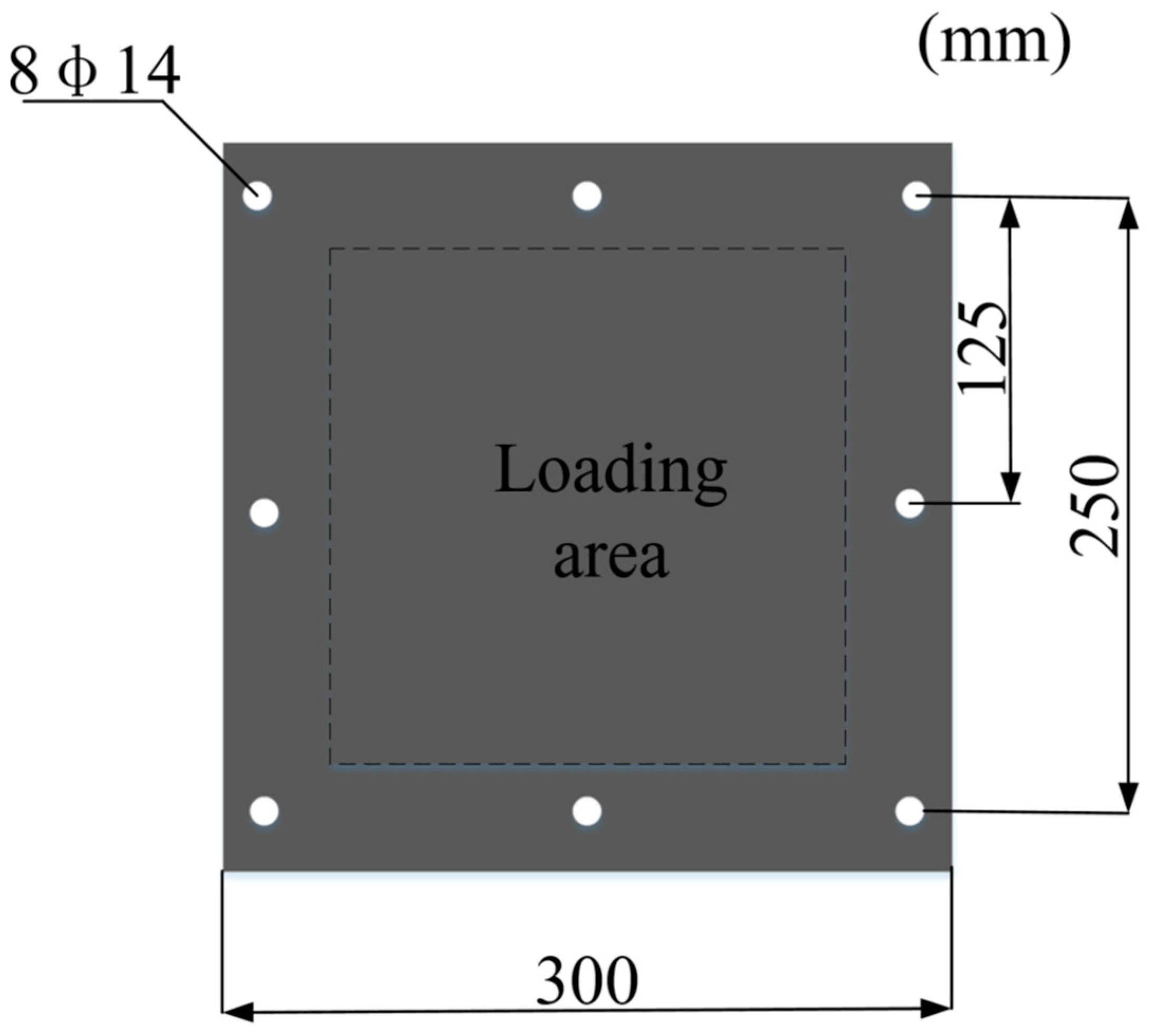
2.1. Specimen Design

To study the influence of aramid–steel composite target (ASCT) plates with different configurations on their antiknock performance, three ASCT plates with different configurations of the surface density of 30.88 kg/m2 were designed in this study: respectively, SA, AS, and SAS, as shown in Table 1. Plate SA and plate AS indicate that aramid laminates are stuck on the back and face of the ASCT plate. The ASCT plate with aramid sandwiched between the two steel plates is called SAS. To compare the antiknock performance of single-layer steel plate and ASCT plates, a single-layer steel plate with an area density of 31.2 kg/m2 (recorded as S) was used, and the deviation between the two is only 1%, meeting the principle of equal area density required by the design. Table 1 shows the sticking methods of single-layer steel plates and ASCT plates with different configurations. The size of the test plate is shown in Figure 1, and the total area density is calculated as follows [14]:
ρ = ρ s h t s + ρ a h t a
where ρs is the mass density of the steel, ρa is the mass density of aramid laminates, and hts and hta are the thickness of steel and aramid laminates, respectively. Obviously, for a pure steel plate, ht equals its thickness hts, and hta equals zero.
In consideration of material properties and manufacturing costs, this study selects Q235 steel and aramid laminates commonly used in industry to prepare ASCT plates. The size of the target plates is 400 mm (long) × 400 mm (wide). The surface of the base steel plate shall be polished, degreased, and sandblasted before sticking, to improve the surface roughness and the bonding strength of the steel plate and aramid laminates. Aramid laminates are made of aramid prepreg and provided by the Northern Academy of Materials Science and Engineering. Aramid laminates are made of stacked aramid fiber prepregs that are put into a hot press and hot pressed for 90 min at a pressure of 10 MPa and a temperature of 160 °C. This process is often used to manufacture fiber-reinforced resin composites. This kind of light product is produced by a vacuum resin-pouring process, which obtains a good fiber–resin ratio in the material, thus producing a light product with the best characteristics of the reinforced fiber. WT-601 low-temperature turns to cure super thick film polyurethane elastic coating are used to stick aramid laminates with steel plates. The coating film is hard, bright, flexible, and excellent in wear resistance, corrosion resistance, anti-collision performance, and good in low temperatures. It has good adhesion to concrete, steel, cast iron, aluminum, wood, and other substrates, and is provided by the Northern Institute of Materials Science and Engineering. The adhesive film is placed between the aramid laminate and the steel plate at room temperature, and the assembly of the steel plate, the adhesive film, and the aramid laminate are sealed with a sealing bag. The components are placed on a press and pressed at 1.0 MPa pressure at room temperature for 2 to 5 min to form an aramid laminate/steel composite structure. The manufacturing process is shown in Figure 2.

2.2. Test Device

Figure 3a shows a schematic diagram of a detailed test setup for explosion testing. The allowable size of the test fixture system is a 400 mm (long) × 400 mm (wide) plate to be fully edge-camped with a 10 mm thick picture frame together with a series of bolts of diameter 16 mm, as shown in Figure 3b. The pressing plate and the support plate have the same structure, forming a pair of zigzag flange structures for clamping the target plate. The size of the square notch in the middle of the flange structure is the shock wave loading area, which is 335 mm × 335 mm, and the height of the whole unit is 700 mm. Since there is a hollow area below the exposed area, an unrestricted deflection of the slab can be observed. The fixture system is connected to the ground through rivets to ensure its stability, as shown in Figure 3a. A 75 g cylindrical TNT explosive with a detonation radius of 15.0 mm and height of 70.0 mm is selected as shown in Figure 3c. The blasting distance is the distance between the upper surface of the plate and the center point of the explosive. The TNT explosive column is hoisted above the center line of the plate through the L-shaped reinforcement and fixed with three ropes. The explosive is detonated by a detonator, which is buried on the side far from the test plate, as shown in Figure 3b. The test piece is placed on the top surface of the frame, the four sides of the test piece are fixed, and the bottom of the test piece is placed in the air to simulate the empty state. Test conditions are shown in Table 2.

2.3. Test Result

2.3.1. Single-Layer Steel (S-1) Plate

The deformation morphology of the steel plate under 75 g TNT charge is shown in Figure 4. Due to the local effect of the explosive, the steel plate has obvious pits in the central area, and there is a certain burning discoloration phenomenon in the pits, which is caused by the high-temperature detonation products produced in the initial stage of the explosion [10]. The diameter of the pits measured is about 70.00 mm, and the diameter of the generated burns is about 40.00 mm. The steel plate has a large tensile deformation on the back, and the central area is locally raised. From the side view, it can be seen that except for the central area, the deformation of other areas of the plate is small. The maximum deflection of the plate is in the center, with a central deflection of 28.09 mm. The constraint boundary around the plate has not been deformed, and the fixed screw holes have not been sheared. At this time, the whole plate is in plastic deformation and has not been broken.

2.3.2. Single-Layer Steel (S-2) Plate

The failure morphology of the S-2 steel plate specimen is shown in Figure 5. Due to the strong local effect of near-field explosion load, regular circular pits are formed in the center of the steel plate, and obvious necking also occurs in the center area. Figure 5a shows a crack appeared in the necking area of the steel plate. By observing the cracks, it can be found that tearing failure occurs in some areas of the cracks. There is only one slight crack in the pit, which is generally considered smooth and flat. In Figure 5b, it can be seen that the crack runs through the local part of the plate, and there is tearing, but the surface behind the dent is smooth and flat. By measuring the diameter of the plate dent (81.12 mm) and the center deflection (30.1 mm), it can be seen that the steel plate has strong plastic deformation capacity.
Figure 6 shows the local micromorphology of the crack section of the S-2 plate after explosion, the blasting face in the damaged area, and the blasting face in the non-damaged area (enlarged by 2000 times). It can be seen from Figure 6a that a large number of small cracks are produced in the fracture section of the crack, and the surface cracks are disordered and uneven. It can also be seen that the metal in this area has undergone rapid heating, quenching, and residual stress from surrounding materials, and the fracture caused tearing damage. The unevenness is due to the melting of the high-temperature fracture-section metal generated by the explosion. After the explosion, the temperature immediately decreases, resulting in the metal changing from a solid to viscoelastic state, and the fracture metal solidified into flakes and attached to the surface of the section. According to Figure 6b, the surface of this area is increased in a scale-like dispersion pattern, and the surface is disordered and uneven without obvious cracks, and there are many tear layers. It can be seen that the metal is subjected to high temperature and a strong shock wave when resisting the explosion, resulting in different degrees of tear damage and a large amount of metal melting on the surface. It can be seen from Figure 6c that the surface of the non-destructive area is relatively smooth, and there is no melting and tearing damage, indicating that the edge metal is less affected by the explosion load, and most of the energy generated by the explosion is released at the center of the plate.

2.3.3. Back Burst Side Stuck ASCT (SA) Plates

The failure morphology of the ASCT (SA) plate under 75 g TNT charge is shown in Figure 7. The front steel plate layer has plastic deformation as a whole, without failure. Due to the local effect of the explosive, the steel plate has obvious pits in the central area, and there is an obvious plastic hinge phenomenon at the boundary and diagonal. The diameter of the pit is about 50.00 mm, and the diameter of the burned pit is about 35.00 mm. In addition to the bulge deformation area behind the steel plate in Figure 7b, the overall plate has a very small deformation. The maximum deflection of the plate is at the center, and this measures 24.7 mm. The constraint boundary of the plate has no deformation, and the fixed screw hole has no punching deformation. It can be seen from the side that the bonding between the steel plate and the aramid laminate is very firm, and there is no delamination between them. Except that the aramid fiber broke in the area of 22.42 mm in the center diameter of the area closest to the explosive at the back of the aramid laminate, the fiber of the whole plate was not damaged, and the difference in the compression strength between the steel plate in the composite target plate and the aramid laminate showed different failure forms.

2.3.4. Blast Side Stuck ASCT (AS) Plates

The deformation morphology of the ASCT (AS) plate under 75 g TNT charge is shown in Figure 8. Under the action of high temperature and sparse stretching of the explosion reflected wave, a square failure area of about 60 mm × 60 mm was generated in the center area of the aramid layer on the face of the explosion. There are scorch marks of varying degrees at the edge of fiber and the part of the layer facing the explosion. In Figure 8b, asymmetric petal damage occurred in the central area of the steel plate layer on the back. One of the petals was reversed. The fracture of the petal tip in the front steel layer indicates that there was a strong tensile tear before the petal fracture, which indicates that before the petal fracture, a relatively serious local tensile tear occurred at the edge of the initial hole of the plate. It was measured that the damage diameter in the central area of the test plate was about 26.08 mm. It can be seen that the impact resistance of the steel plate cannot be improved by pasting aramid laminates on the explosion face, but rather the damage of the steel plate is aggravated. In addition, to the central area of the back steel plate, failure occurred, which was conducive to the release of the shock wave. There was no obvious plastic hinge phenomenon at the steel plate boundary and diagonal, and the whole plate had a small plastic deformation.
Figure 9 shows the local micromorphology of the damaged and non-damaged areas of the AS-1 plate after the explosion (enlarged by 200 times). Figure 9a shows that in the damaged area, it can be observed that the aramid fiber bundle has been pulled out from the matrix, and serious wrinkles have occurred, and the end of the broken fiber has a large degree of fibrillation. Figure 9b shows that compared with the damaged area, the aramid fiber bundles in the non-damaged area are wrapped by the matrix and arranged orderly.
Figure 10a shows the microstructure of the aramid plate in different areas. The corresponding diffraction peak of the specimen was observed in the XRD diagram. The peak of the aramid plate in different areas has no obvious change. It can be inferred that the phase transformation does not occur in the aramid laminates in different regions, but the front and back peaks of the non-destructive region of the steel plate, as shown in Figure 10b, change obviously, indicating that the phase transformation occurs.

2.3.5. Aramid Sandwich ASCT (SAS) Plates

The damage diagram of the ASCT (SAS) plate under 75 g TNT charge at an explosive distance of 50 mm is shown in Figure 11. The front and rear steel layers are completely torn, resulting in an initial blanking notch. The diameter of the generated through-hole channel is about 35.00 mm. Under the impact load of the front panel and the core erosion material fragments, the central area of the rear panel shows a small amount of “petal-shaped” tearing. At this time, an initial blanking notch similar to a contact explosion is generated under a close explosion. This is due to the local tensile tearing of the explosive near the plate under the high pressure of the shock wave, resulting in the initial perforation. Because most of the impact energy generated by the central hole of the plate is dissipated through the central hole, the plastic hinge phenomenon and overall deformation of the sandwich aramid layer are reduced to a certain extent.

3. Numerical Model

3.1. Finite Element Model

Due to the short duration of the shock wave acting on the composite target plate and the short dynamic response of the structure in the explosion test, it is difficult to conduct an in-depth analysis of the explosion process through the test. Therefore, this paper establishes a finite element model to predict the damage mechanism and failure mode of the structure under the action of an explosion. In the finite element model, the steel, aramid layer, glue, and air are three-dimensional solid elements, the TNT explosive is volume filled, and the model is established using an arbitrary Lagrangian–Eulerian (ALE) algorithm. Considering the symmetry of the explosion load and ASCT plate structure, a quarter model is established. The two outer edges and two symmetry planes of the model are, respectively, subject to fixed boundary conditions and symmetric boundary conditions. The air area is 250 mm long, 250 mm wide, and 200 mm high. To improve the accuracy of the numerical simulation results and save calculation time, two different grid sizes are used in the model. The unit size near the model center is 1 mm × 1 mm × 1 mm; the element size near the boundary is 3 mm × 3 mm × 3 mm. Using the keyword *CONTACT_AUTOMATIC_SURFACE_TO_SURFACE_TIEBREAK [34] defines the bonding force between the steel plate and aramid layer. In the calculation, when the stress at the interface of the two layers meets Formula (2), the aramid laminate will be delaminated. The interaction between steel plate and aramid laminates was also simulated by using this contact [32].
( σ n S n ) 2 + ( σ s S s ) 2 1
where σ and S are stress and strength values, and n and S are normal and shear directions. In the contact setting options, NFLS is the tensile failure stress, SFLS is the shear failure stress, and NFLS and SFLS are, respectively, 34.5 MPa and 9 MPa as interlaminar failure parameters [32]. At the same time, by adding the keyword *MAT_ADD_EROSION controls the unit failure of the steel plate and aramid fiber composite [35]. We utilize the keyword BOUNDARY_NON_REFLECTING to define the edge of the airspace as a non-reflective boundary and place the TNT explosive at the center of the upper surface of the model. The three-dimensional model structure diagram established is shown in Figure 12.

3.2. Material Model

Modeling the strain-rate-related behavior of steel and aramid laminates is the key to accurately simulating the deformation of plates, in particular, because local explosive loads are expected to produce stresses that exceed the yield strength of the material. The material model must be able to capture nonlinear stress-strain behavior beyond the elastic limit.

3.2.1. Steel Plate

The Johnson–Cook [36] model established by Johnson and Cook is used to describe the mechanical behavior of Q235 steel. Assuming that the material strength is isotropic and not affected by the average stress, it is described as
σ = [ A + B ε n ] [ 1 + C I n I n ε ] [ 1 T m ]
where σ is the equivalent stress, ε is the equivalent plastic strain, ε ˙ * is the dimensionless equivalent plastic strain rate, A is the reference strain rate, B and n are the strain hardening modulus and hardening parameter of the material at the reference temperature, C is the strain hardening parameter, m is the thermal softening parameter of the material, and T* is the relative temperature. This paper adopts the Johnson–Cook failure criterion for Q235 steel, which can be described as
ε f = [ D 1 + D 2 exp ( D 3 σ ) ] [ 1 + D 4 I n ε ] [ 1 + D 5 T ]
where σ* = σm/σ is stress triaxiality, σm is the hydrostatic pressure, and σ is Mises equivalent stress; D1~D5 are material parameters, where D1~D3 are fracture-damage parameters related to stress triaxiality, D4 is the fracture-damage parameter related to strain rate, and D5 is the fracture-damage parameter related to temperature. Specific parameters are shown in Table 3.

3.2.2. Adhesive

Polyurethane adhesive is a strain-rate-sensitive material, so it can be regarded as a viscoelastic material [38]. The Cowper–Symonds constitutive model can be described as
σ Y = [ 1 + ( ε c ) 1 p ] ( σ 0 + β E p ε p e f f )
where σ0 is the initial yield stress, ε ˙ is the strain rate, c, P is the strain rate parameter, ε p e f f is the effective plastic strain, β is the plastic strain parameter, and ε p e f f is the plastic hardening modulus, which can be obtained from the following formula:
E p = E tan E E E tan
where Etan is the tangent modulus. Specific material parameters are shown in Table 4.

3.2.3. Aramid Fiber Composite

The single-layer plate is equivalent to a continuous, homogeneous, and orthotropic material by using the macro mechanical analysis method. In this paper, the Chang–Chang [40] failure criterion is adopted for the damage of aramid fiber laminates, and the specific definitions are as follows:
Fiber tensile failure:
σ a a > 0 , e f 2 = ( σ a a X t ) + β ( σ a b S c ) 1 0
Fiber compression failure:
σ a a < 0 , e c 2 = ( σ a a X c ) 2 1 0
Matrix tensile failure:
σ b b > 0 , e m 2 = ( σ b b Y t ) + ( σ a b S c ) 2 1 0
Matrix compression failure:
σ b b < 0 , e d 2 = ( σ b b 2 S c ) 2 + [ ( Y c S c ) 2 1 ] ( σ b b Y c ) + ( σ a b S c ) 2 1 0
In the above formula, σaa is the fiber direction stress, σab is the in-plane shear stress, σbb is the stress in the direction of the matrix, ef is the fiber tensile failure factor, ec is the fiber compression failure factor, em is the matrix tensile failure factor, ed is the matrix compression failure factor, β is the influence factor of shear stress, Xt is the tensile strength of the fiber, Xc is the fiber compression strength, Yt is the tensile strength of the matrix, Yc is the compressive strength of the matrix, and Sc is the in-plane shear strength. Four different failure modes simulate the mechanical properties of single-layer composites. The material parameters of a single-layer plate are shown in Table 5.

3.2.4. Air and Explosives

In the process of numerical simulation, the JWL equation of state is used to describe the pressure of explosive detonation products:
p = A ( 1 ω R 1 V ) e R 1 V + B ( 1 ω R 2 V ) e R 2 V + ω E V
where P is the pressure of detonation products, V is the relative volume, E is the chemical energy released per unit volume, and A, B, R1, R2, and ω are constants determined by experiments. See Table 6 for parameters of the TNT explosive and JWL equation of state ω .
With air selection *EOS_LINEAR_POLYNOMIAL linear polynomial equation of state, the pressure in the medium is
p = C 0 + C 1 μ + C 2 μ 2 + C 3 μ 3 + ( C 4 + C 5 μ + C 6 μ 2 ) E
where E is the chemical energy released per unit volume, μ is the relative volume, and C 0 , C 1 , C 2 , C 3 , C 4 , C 5 , and C 6 are constant. See Table 7 for specific parameters and material parameters

3.3. Comparison between Test Results and Numerical Results

3.3.1. Single-Layer Steel (S-1) Plate

The damage test and numerical simulation results of the steel plate specimen with 75 g TNT charge at 50 mm explosion distance are shown in Figure 13. A 70.00 mm diameter blasting pit appeared on the blasting face. In the numerical simulation, the diameter of the model blasting pit was about 65.30 mm, with an error of 6.7%; the central deflection of the plate is 28.09 mm. In the numerical simulation, the central deflection of the plate is 28.05 mm, and the error is only 0.1%. From the side view, it can be seen that the deformation of other areas of the plate is very small except for the local uplift area, and the target plate and the clamp have no shear failure. The results show that the numerical simulation results are in good agreement with the experimental results.

3.3.2. Single-Layer Steel (S-2) Plate

The test and numerical simulation damage results of the S-2 steel plate specimen under the action of 75 g TNT charge at 50 mm explosion distance are shown in Figure 14. The diameter of the front surface pit is 90.00 mm, and the central displacement deflection is 30.01 mm. In the numerical simulation, the diameter of the model pit is 86.50 mm, and the central displacement deflection is 30.57 mm, with errors of 3.89% and 1.63%, respectively.

3.3.3. Back Burst Side Sticked ASCT (SA) Plates

The damage experiment and numerical simulation results of the ASCT (AS) plate are shown in Figure 15. The diameter of the front surface blasting pit is 50 mm. In the numerical simulation, the diameter of the model blasting pit is 46.8 mm, with an error of 6.4%. In Figure 15a, the central deflection of the plate is 24.7 mm. In the numerical simulation, the central deflection of the plate is 26.48 mm, with an error of 1.9%. In Figure 15b, the fiber breaks in the 22.42 mm area on the back of the aramid laminates. In the numerical simulation, the fiber breaks in the 21.5 mm area on the back of the aramid laminates, with an error of 4.1%. In the numerical simulation, it can be seen that there is no glue opening between the steel plate and the aramid laminates, and there is no delamination between the aramid laminates. The results show that the error between the numerical simulation results and the experimental results is within 10%, and the overall failure of the plate can be well simulated.

3.3.4. Blast Side Sticked ASCT (AS) Plates

The damage test and numerical simulation results of the aramid plate under 75 g TNT charge pasted on the blasting face at 50 mm explosion distance are shown in Figure 16. Under the action of high-temperature combustion, the aramid layer on the front surface produced a fiber failure area with a diameter of 25.59 mm, and the steel plate had a hole diameter of 26.08 mm. In the numerical simulation, the failure diameter of the aramid layer on the front surface is 28.00 mm, and the hole diameter of the steel plate is 24 mm, with errors of 9.42% and 8%, respectively. In the process of numerical simulation, the failure of the aramid layer and steel plate can be well simulated, and the error range is within 10%. The failure of the central area is mainly because the stress generated by the explosion shock wave propagates mainly along the fiber-braiding direction. The high tensile strength in the fiber-braiding direction causes the fabric to deform. At the same time, a reflection is formed on the surface of the fabric, and a pressure concentration zone is generated in a certain area. Therefore, the shear failure in the laminate plane causes a large number of fibers to be pulled out, and the matrix is cracked by attaching to the extracted fibers.

3.3.5. Aramid Sandwich ASCT (SAS) Plates

Figure 14 shows the damage test and numerical simulation results of the SAS specimen under the explosion of a 75 g TNT charge at a distance of 50 mm. In Figure 17a, a circular through-hole is generated in the central area of the front surface of the ASCT specimen. The diameter of the perforation channel is 35.00 mm. In the numerical simulation, the diameter of the perforation channel is 34.5 mm, and the error is 1.43%. The diameter of the front steel plate hole is 35.00 mm. In the numerical simulation, the diameter of the perforation channel is 34.50 mm, and the error is 1.43%. The hole size of the rear steel plate is 36.26 mm in diameter. In the numerical simulation, the diameter of the perforation channel is 35.5 mm, with an error of 2.1%. The damage size of the front and rear steel plates and the damage of the sandwich aramid laminates were well simulated.

3.4. Anti-Explosion Performance Analysis of Single-Layer Steel Plate and ASCT Plates with Different Configurations

In addition to the principle of equal area density, the principle of equal thickness of the base material was followed: under the same explosion impact load, the single-layer steel plate with the same thickness as the ASCT plate substrate was tested. A comparative study of the blast resistance of equal thickness substrates with and without the application of aramid laminates was conducted. The test and numerical simulation results of the same thickness single-layer steel plate (S-2) are shown in Figure 11 and Figure 15. The center displacement deflection of the ASCT (SA) plate is 18% less than that of plate S-2 under the 75 g TNT charge at an explosion distance of 50 mm, which shows that pasting aramid laminate on the back explosion surface of steel plate with equal thickness can effectively improve the anti-explosion performance of steel plate.
The damage data of the single-layer steel plate and ASCT plate are shown in Table 8. It can be observed that under the condition of equal area density, the ASCT (AS) plate cannot improve the impact resistance of the steel plate, but rather aggravates the damage of the underlying steel plate. Under the same explosive conditions, the ASCT (SAS) plate directly suffered from punching failure. Compared with the first two pasting methods, ASCT (SA) plate shows better anti-explosion performance, and its central displacement deflection is reduced by 12% compared with the single-layer steel plate (S-1). Because aramid laminates have a high-lateral-bearing capacity and strong shear resistance, ASCT (SA) plates bear higher ultimate loads in both horizontal and vertical directions. Through numerical simulation, the relationship between TNT dosage for the critical failure of single-layer steel plates and ASCT plates with different structural configurations is found, as shown in Figure 18. The SA plate is damaged when the dosage is 155 g. Compared with plates S-1 (145 g), S-2 (135 g), AS (45 g), and SAS (55 g), the SA plate can withstand a larger dosage of explosive to ensure that the steel plate will not be damaged and protect the safety of personnel and equipment behind the structure. From the above tests and numerical simulation analyses, it can be shown that the anti-explosion performance of the steel plate with aramid laminates on the back explosion surface is effectively improved under the condition of equal surface density.

4. Analysis of the Energy Dissipation Mechanism of the Aramid Layer in ASCT (SA) Plate

Through the comparison and analysis of ASCT plates with different configurations, it can be seen that the protective effect of plate SA is better than that of plate AS and plate SAS, which indicates that the structure of the materials will also affect their shock wave attenuation effect. When the stress wave changes suddenly through the material, reflection and transmission will occur. According to the transmission formula of waves in different materials [45,46], it can be seen as
T = 2 1 + ρ 1 c 1 / ρ 2 c 2
σ T = T σ I
In Equation (13), T is the transmission coefficient, ϲ is the wave velocity, and ρ is the density of the material. The wave impedance of the material is the material density ρ and wave velocity c. Therefore, it can be seen from the above equation that the transmission coefficient T is only related to the wave impedance of the two materials. In Equation (14), where σT is the transmission stress, and σI is the transmission stress, when Equation (13) T is brought in, the attenuation of the wave can be known. Therefore, the transmission coefficient directly determines the attenuation effect of the shock wave. If the wave impedance of the material is arranged in a decreasing manner, the transmission coefficient will be lower, the transmission pressure will be lower, and the attenuation of the incident wave will be stronger. The density and wave velocity of steel is greater than that of aramid, and the wave impedance of Q235 steel is much greater than that of aramid material. When the shock wave enters the aramid material through the steel plate, its strength can be attenuated to a large extent, so the sample SA effectively attenuates the strength of the incident wave. When the AS shock wave of the sample enters the steel plate through the interface between the aramid layer and the steel plate, the strength of the wave will be enhanced, instead, and the damage to the steel plate will be intensified.
The ASCT (SA) plate is analyzed according to the propagation law of stress waves. Because the time of the shock wave acting on the target plate under near-field explosion load is very short, the wave strength changes after the shock wave passes through the ASCT (SA) plate. This is because once the shock wave touches the surface of the target plate, it will generate a compressive stress-wave front, which will propagate along the thickness direction. When these compression waves ∆σI reach the interface between the aramid layer and the steel, some of them are reflected in the form of anti-directional reflected compression waves ∆σIR, as shown in Figure 19. Because the wave impedance of the steel and aramid layer are different, according to the transmission formula of a wave in different materials, the incident wave ∆σC forms a transmission wave ∆σT when it passes through the steel plate and enters the aramid laminate. When the transmission wave ∆σT reaches the aramid laminate, the aramid laminate quickly enters a high-strain state. The pressure of the transmission wave propagates along the direction of the fiber warp–weft-interlaced plies. When these compression waves ∆σI reach the interface between the aramid layer and the air, they will be reflected in the form of reflected tensile waves ∆σTR in the opposite direction.
On the other hand, a series of stresses are generated under the action of these continuous wave reflections. Due to the high rigidity and toughness of the steel plate, it can play a supporting role and absorb energy through its own plastic deformation. The high tensile strength of the aramid fiber further hinders the deformation of the steel plate. The steel plate and the aramid fiber dissipate ∆σI and ∆σT through deformation, and when the ∆σIR tensile stress exceeds the tensile strength of the aramid fiber, it will cause the fracture of the resin matrix of the aramid laminate and the delamination between different material layers and the tensile fracture of the aramid fiber, which will further consume the stress. When the strength of ∆σI is too high, the movement of the front steel layer becomes the main factor for the failure of the rear aramid layer, which deforms the rear aramid layer and then breaks with the front steel layer, as shown in Figure 20. Relevant literature shows that [24] after the aramid fiber plain weave fabric is added to the matrix, the friction between the aramid fiber and the matrix interface is increased. Under the action of shock waves or in the process of resisting the deformation of the steel plate, the fiber is drawn out of the matrix. To resist the friction between the fiber and the matrix interface and cause resin cracking, the impact load can be further reduced.
A TNT explosion is an extremely rapid chemical energy release process, that is, in a very short period of time, a form of explosive can release a large amount of energy to cause high-pressure chemical reaction or state change in the structure. A protective structure is designed to absorb the energy generated by the explosion to protect the personnel and equipment inside the structure from damage. Figure 21 shows the energy absorption comparison of the two structural forms. The black line is the energy absorption of single-layer steel plate, and the red line is the energy absorption of the steel plate of the aramid adhesive layer composite structure., At the back of the explosive surface of the bonded aramid-laminated steel plate, energy absorption is significantly reduced. Figure 22 shows the energy absorption of the aramid layer. The energy absorbed by the aramid layer accounts for only 5% of the energy absorbed by the steel plate, thereby reducing the center deflection of the steel plate by 12%. Pasting the aramid laminate on the back surface of the steel plate can effectively increase the blast resistance of the steel plate.

5. Failure Mode and Dimensionless Analysis of ASCT (SA) Plate

5.1. Failure Mode Analysis

G. N. Nurick et al. [47] observed three failure modes different from the uniformly distributed load in an experiment of clamped square plates under localized blast loading: mode Itc (plastic large deformation with necking in the middle), mode II* c (partial tearing in the central area), and mode IIc (complete tearing in the middle with “cap-shape” failure). G. N. Nurick et al. [48] conducted a comprehensive analysis of the deformation and fracture of thin plates under localized blast loading. The three stages of the dynamic response are described in detail: namely, disc shape, cut shape, and petal shape. T. J. Cloete et al. [49] researched the deformation and shear failure of clamped circular plates around a central support under local explosion and proposed the concept of defining the failure mode according to whether there is a large plastic deformation when tensile tearing (or shear failure) occurs. On this basis, combined with the results of the test and numerical simulation, the failure mode of the aramid-bonded laminated steel (ASCT) plate is studied. Under the condition that other parameters remain unchanged, the failure mode of the exploded surface of a sticked aramid-laminated plate with the explosive amount within the range of 15 g–155 g is classified, as shown in Figure 23.
In the elastic-deformation mode, as shown in Figure 23a, the steel plate is in the stage of large elastic deformation. The steel plate is a plastic material that resists the energy generated by the explosion through deformation. The aramid laminates have good tensile properties. At this time, the aramid laminates and the steel plates are close together. During this process, the aramid laminates resist the deformation of the steel plate, and the resin and aramid fibers in the aramid laminates are not damaged.
In the matrix-cracking mode, as shown in Figure 23b, the steel plate is in the stage of large inelastic deformation. Under the large deformation of the steel plate, the aramid fiber has not exceeded its tensile strength. The resin used for curing first cracks, and the aramid fiber is still in the range of elongation without tensile failure.
In the fiber-fracture mode, as shown in Figure 23c, the plastic deformation of necking occurs in the middle of the steel plate. Under the condition of the large deformation of the steel plate, the resin cracks and delaminates. The force on the fiber exceeded its tensile strength. The aramid fiber was pulled out from the resin matrix and tensile fracture occurs.
In the “cap-shape”-failure mode, as shown in Figure 23d, the plastic deformation of the steel plate exceeds its own ultimate tensile strength, and the resin of the aramid laminate on the back explosive surface further cracks on the basis of the sealing layer. The aramid fiber is pulled out of the resin matrix, tensile fracture occurs, and the middle part is completely torn. The middle part of the steel plate occurs and a “cap-shaped” punching block appears on the back.

5.2. Dimensionless Analysis

The response of the ASCT (SA) plate under the action of explosion load involves multiple physical quantities, which is difficult to describe with the aid of or by using the previous physical and mathematical models and equations. Therefore, the physical quantities involved in the problem can be classified by attributes to find out the relationship between different physical quantities and the causal relationship between physical quantities. This method is called dimensionless analysis. The schematic diagram of the interaction between the cylindrical TNT and the composite target is shown in Figure 24. Under the condition that the structure is not damaged, the central deflection of the composite target is taken as one of the important indicators of the antiknock performance. The physical quantities of the central deflection of the composite target plate include the following aspects:
  • Physical parameters of cylindrical TNT, including TNT charge Q, charge density ρe, and internal energy Ee released by unit mass explosive.
  • Relevant physical parameters of steel plate, including density ρs, elastic modulus Es, yield strength σs, thickness D, and the side length of steel plate l.
  • Physical parameters of aramid laminates, including density ρa, elastic modulus Ea, tensile strength σa, thickness d, and dimension la.
  • Adhesion between steel plate and aramid laminate, including tensile failure stress σ and shear failure stress τ.
  • Burst center distance parameter: the vertical distance h from the center of the cylindrical charge to the target plate surface.
Based on the above physical parameters, the relationship function between the maximum displacement W of the steel plate and each physical quantity can be written as
W = f ( Q , ρ e , E e ; ρ s , E s , σ s ; D , L ; E a , σ a , d , L a ; σ , τ ; h )
Select charge density ρe, the internal energy Ee released by unit mass explosive, and the thickness D of steel plate are taken as basic quantities, and (14) can be changed into
W D = f ( Q / ρ e 3 D , ρ S ρ e , E S ρ s E e , σ S ρ s E e , l D , ρ a ρ e , E a ρ s E e , σ a ρ s E e , d D , l a D , σ ρ s E e , τ ρ s E e , h D )
When the adhesive force between the steel plate and the aramid plate, the geometric size and thickness of the aramid plate, and the burst center distance are kept unchanged, Formula (15) is reduced to a simple dimensionless relationship, that is
W D = f 1 ( Q / ρ e 3 D )
When the size and thickness of the aramid plate, the adhesive force between the steel plate and the aramid plate, and the explosive amount remain unchanged, Formula (15) can be changed into a simple dimensionless relationship, that is
W D = f 2 ( h D )
When the dimension la of the aramid layer, the adhesive force between the steel plate and the aramid plate, the explosive amount, and the explosive height are kept unchanged, Formula (15) can be changed to
W D = f 3 ( d D )

5.2.1. Effect of Bursting Distance on the Deflection of the Center of an ASCT (SA) Plate

Keep the thickness and explosive amount of aramid laminates unchanged and change the distance between explosion centers (to 40 mm–110 mm) to analyze the influence of explosion center distance on the maximum midspan displacement of the ASCT (SA) plate. First, the maximum midspan displacement data of plate SA are dimensionless processed, and then the dimensionless data are fitted with a power function to obtain the dimensionless relationship curve as shown in Figure 25. Under the condition that its amount is unchanged, with the increase in the explosion center distance, the index number of the steel plate central displacement deflection decreases, and the fitting relationship is W D = 685.4 ( h D ) 1.732 .

5.2.2. Effect of TNT Charge on the Deflection of the Center of the ASCT (SA) Plate

Keep the thickness of aramid laminate and explosive height unchanged and change the explosive mass (35 g–145 g) to analyze the influence of the explosive amount on the maximum midspan displacement of the composite target. First, the maximum midspan displacement data of plate SA are dimensionless processed, and then the dimensionless data are fitted with a power function to obtain the dimensionless relationship curve as shown in Figure 26. Under the condition that its amount remains unchanged, with the increase in TNT dosage, the central displacement and deflection of the steel plate increase exponentially. The fitting relationship is W D = 2.85 ( Q / ρ e 3 D ) 3.376 . With the increase in the explosive charge, the composite target plate shows different damage modes, keeping the explosion center distance of 50 mm unchanged. When the TNT charge is increased to 155 g, the middle of the steel plate is completely torn, and a “cap-shape” failure occurs. It is no longer suitable to use the center deflection to measure the antiknock performance.

5.2.3. Effect of Aramid Layer Thickness on the Central Deflection of ASCT (SA) Plates

Keep the mass and height of explosives unchanged, change the thickness of aramid laminates (1 mm~8 mm), and analyze the influence of aramid laminates on the maximum midspan displacement of plate SA. First, the maximum midspan displacement data of the composite target plate are dimensionless processed, and then the dimensionless data are fitted with a linear function to obtain the dimensionless relationship curve as shown in Figure 27. With the increase in the thickness of aramid laminates, the center displacement deflection of the steel plate decreases linearly with the increase in its amount. The fitting relationship is W D = 8.087 1.687 ( h D ) .

5.2.4. Empirical Formula of Central Deflection

To accurately predict the central deflection of an aramid–steel composite target plate under local explosion, based on the above fitting data of a single factor curve, the data of explosive center distance–explosive charge–aramid layer thickness–central deflection are shown in Table 9. The empirical formula of explosive charge–explosive center distance–aramid layer thickness–central deflection is obtained by power function analysis:
y = 219.840 x 1 1.720 x 2 3.444 x 3 0.251 0.037
where x1 is the blast center distance; x2 is the dosage; x3 is the thickness of the aramid layer; and y is the central deflection of the plate. The correlation coefficient R = 0.99 and the deflection empirical formula are in good agreement with the numerical calculation results. The formula can well fit the relationship between the central deflection and the distance between the detonation center, the amount of explosive, and the thickness of the aramid layer.

6. Conclusions

In this study, single-layer steel plate and aramid–steel composite target plate specimens with different structural configurations were designed and fabricated. The tests under local explosion load were carried out on the specimens. It was proved that the composite method of pasting aramid laminates on the back surface of steel plate can effectively improve the anti-explosion performance of steel plate. The explosion resistance, failure characteristics, and damage mechanism of different structural configuration plates were studied. The destruction patterns under the action of different TNT charges were analyzed by using LS-DYNA software. The ASCT (SA) board that performed the quantitative analysis fitted the empirical expression. The following conclusions can be drawn:
  • The structural configuration of the explosion-proof surface of the steel plate stuck aramid laminate can effectively improve anti-explosion performance. The test phenomena of the single-layer steel plate and ASCT plate under local explosive load are better consistent with the numerical simulation results. Through a series of different structural configurations of the explosion-resistant properties of ASCT plates, it was observed that the aramid laminate pasted on the back explosion surface of the steel plate effectively shortened the diameter of the explosion pit and reduced the center displacement deflection. The critical destructive TNT doses of single-layer steel plates and ASCT plates with different structural configurations were obtained through numerical simulation, which determined the best explosion resistance of the ASCT (SA) plate structure configuration.
  • The anti-explosion mechanism of ASCT (SA) plate was analyzed from the perspective of stress wave propagation and energy absorption. The shock wave fabricated by the explosion generates reflection and transmission at the interface between the steel and aramid layer. Changing the propagation direction of the stress wave, the aramid layer reduces the strength of the reflected tensile stress wave. Aramid fiber possesses a large elastic modulus and elongation, which can absorb the energy generated by explosions and provide deformation resistance for steel plates.
  • The failure modes of the ASCT (SA) plate under different TNT charge, explosive center distance, and aramid laminate thickness were analyzed by experiment and numerical calculation, and the corresponding empirical formulas were given. The results show that the central displacement deflection of the ASCT (SA) plate has an exponential relationship with TNT charge and detonation center distance. The thickness of the aramid laminate on the back surface of the steel plate has a linear relationship with the center displacement deflection of the ASCT (SA) plate, and the center displacement deflection decreases linearly with the increase in the thickness of the adhesive layer. The obtained empirical formula of central deflection can accurately predict the central deflection of the aramid–steel composite target plate under local explosion.
According to the content of this paper, based on the experimental and numerical results, the optimal configuration combination of aramid and steel plate is to paste aramid laminate on the back explosion surface of the steel plate. According to this conclusion, the best ratio of steel plate and aramid laminate can be further discussed, to discover the best antiknock performance which can be used as a reference for subsequent engineering protection applications.

Author Contributions

Z.G.: Conceptualization, Methodology, Software, Writing—original draft, Writing—review & editing Y.C.: Supervision, Conceptualization, Funding acquisition. Z.W.: Writing—review & editing, Supervision. S.L.: Writing— review & editing, Supervision. W.W.: Investigation, Data curation, Resources, Validation. J.C.: Investigation, Data curation validation. All authors have read and agreed to the published version of the manuscript.

Funding

This research received no external funding.

Institutional Review Board Statement

Not applicable.

Informed Consent Statement

Informed consent was obtained from all subjects involved in the study.

Data Availability Statement

The data that support the findings of this study are available from the corresponding author upon reasonable request.

Conflicts of Interest

The authors declare no conflict of interest.

Nomenclature

The dimensions and structural configuration of the protective structure of the aramid–steel composite target (ASCT) plate are shown in Figure 1 and Table 1. S refers to the steel plate layer, A refers to the aramid layer, SA refers to the steel plate on the blast-attack surface, AS refers to the aramid layer on the blast-attack surface, and SAS refers to the aramid layer added in the middle of the steel plate.
ρsMass density of steel
ρaMass density of aramid board
htshta Thickness of steel and aramid layer
σS Stress and strength value
n,SNormal and shear direction
TTransmission coefficient
cWave velocity
ρMaterial density
σTTransmission stress of steel
σITransmission stress of aramid layer

References

  1. Zhongxian, L.; Du Hao, B.C. A Review of Current Researches on Blast Load Effects on Building Structures in China. Trans. Tianjin Univ. 2006, 12, 35–41. [Google Scholar]
  2. Wang, W.; Yang, G.; Yang, J.; Wang, J.; Wang, X. Experimental and numerical research on reinforced concrete slabs strengthened with POZD coated corrugated steel under contact explosive load. Int. J. Impact Eng. 2022, 166, 104256. [Google Scholar] [CrossRef]
  3. Lan, S.R.; Lok, T.S.; Heng, L. Composite structural panels subjected to explosive loading. Constr. Build. Mater. 2005, 19, 387–395. [Google Scholar] [CrossRef]
  4. Wang, W.; Zhang, D.; Lu, F.; Wang, S.-C.; Tang, F. Experimental study on scaling the explosion resistance of a one-way square reinforced concrete slab under a close-in blast loading. Int. J. Impact Eng. 2012, 49, 158–164. [Google Scholar] [CrossRef]
  5. Wang, W.; Zhang, D.; Lu, F.; Wang, S.-C.; Tang, F. Experimental study and numerical simulation of the damage mode of a square reinforced concrete slab under close-in explosion. Eng. Fail. Anal. 2013, 27, 41–51. [Google Scholar] [CrossRef]
  6. Nurick, G.N.; Gelman, M.E.; Marshall, N.S. Tearing of blast loaded plates with clamped boundary conditions. Int. J. Impact Eng. 1996, 18, 803–827. [Google Scholar] [CrossRef]
  7. Nurick, G.N.; Martin, J.B. Deformation of thin plates subjected to impulsive loading—A review: Part I: Theoretical considerations. Int. J. Impact Eng. 1989, 8, 159–170. [Google Scholar] [CrossRef]
  8. Nurick, G.N.; Martin, J.B. deformation of thin plates subjected to impulsive loading—A review part ii: Experimental studies. Int. J. Impact Eng. 1989, 8, 171–186. [Google Scholar] [CrossRef]
  9. Olson, M.D.; Nurick, G.N.; Fagnan, J.R. Deformation and rupture of blast loaded square plates—Predictions and experiments. Int. J. Impact Eng. 1993, 13, 279–291. [Google Scholar] [CrossRef]
  10. Ramajeyathilagam, K.; Vendhan, C.P. Deformation and rupture of thin rectangular plates subjected to underwater shock. Int. J. Impact Eng. 2004, 30, 699–719. [Google Scholar] [CrossRef]
  11. Rudrapatna, N.S.; Vaziri, R.; Olson, M.D. Deformation and failure of blast-loaded square plates. Int. J. Impact Eng. 1999, 22, 449–467. [Google Scholar] [CrossRef]
  12. Wen, H.M. Deformation and tearing of clamped circular work-hardening plates under impulsive loading. Int. J. Press. Vessel. Pip. 1998, 75, 67–73. [Google Scholar] [CrossRef]
  13. Dm, A.; Plnf, B.; Dw, C.; Ar, D. Evaluation of effectiveness of polymer coatings in reducing blast-induced deformation of steel plates. Def. Technol. 2021, 17, 1895–1904. [Google Scholar]
  14. Hou, H.; Chen, C.; Cheng, Y.; Zhang, P.; Wang, J. Effect of structural configuration on air blast resistance of polyurea-coated composite steel plates: Experimental studies. Mater. Des. 2019, 182, 108049. [Google Scholar] [CrossRef]
  15. Mkar, A.; Sm, B.; Hp, C.; Ammi, D.; Msa, E.; Ahe, F. Investigation of mechanical properties of dual-fiber reinforcement in polymer composite. J. Mater. Res. Technol. 2022, 18, 3908–3915. [Google Scholar]
  16. Rangasamy, G.; Mani, S.; Kolandavelu, S.K.S.; Alsoufi, M.S.; Ibrahim, A.M.M.; Muthusamy, S.; Panchal, H.; Sadasivuni, K.K.; Elsheikh, A.H. An extensive analysis of mechanical, thermal and physical properties of jute fiber composites with different fiber orientations—ScienceDirect. Case Stud. Therm. Eng. 2021, 28, 101612. [Google Scholar] [CrossRef]
  17. Elsheikh, A.H.; Panchal, H.; Shanmugan, S.; Muthuramalingam, T.; El-Kassas, A.M.; Ramesh, B. Recent progresses in wood-plastic composites: Pre-processing treatments, manufacturing techniques, recyclability and eco-friendly assessment. Clean. Eng. Technol. 2022, 8, 100450. [Google Scholar] [CrossRef]
  18. Elsheikh, A. Bistable Morphing Composites for Energy-Harvesting Applications. Polymers 2022, 14, 1893. [Google Scholar] [CrossRef]
  19. Wang, X.Y. Mechanical Analysis and Design of Composite Materials; National University of Defense Technology Press: Changsha, China, 1999; pp. 137–141. [Google Scholar]
  20. Nilakantan, G.; Merrill, R.L.; Keefe, M.; Jr, J.; Wetzel, E.D. Experimental investigation of the role of frictional yarn pull-out and windowing on the probabilistic impact response of kevlar fabrics. Compos. Part B 2015, 68, 215–229. [Google Scholar] [CrossRef]
  21. Ambrosetti, S.; Bozzolo, A.; Dotoli, R.; Bardaro, D.; Fay, S. Textile-Based Luggage Containers for Onboard Blast Protection. SAE Int. J. Aerosp. 2011, 4, 690–698. [Google Scholar]
  22. Vannucci Paolo Masi Filippo Mariano Maria, P. Blast actions in aircrafts: An integrated methodology for designing protection devices. Eng. Struct. 2018, 175, 895–911. [Google Scholar]
  23. Mayo, J.B.; Wetzel, E.D.; Hosur, M.V.; Jeelani, S. Stab and puncture characterization of thermoplastic-impregnated aramid fabrics. Int. J. Impact Eng. 2009, 36, 1095–1105. [Google Scholar] [CrossRef]
  24. Tabiei, A.; Nilakantan, G. Ballistic impact of dry woven fabric composites: A review. Appl. Mech. Rev. 2008, 61, 010801. [Google Scholar] [CrossRef]
  25. Palta, E.; Gutowski, M.; Fang, H. A numerical study of steel and hybrid armor plates under ballistic impacts. Int. J. Solids Struct. 2018, 136–137, 279–294. [Google Scholar] [CrossRef]
  26. Ramadhan, A.A.; Abu Talib, A.R.; Mohd Rafie, A.S.; Zahari, R. High velocity impact response of Kevlar-29/epoxy and 6061-T6 aluminum laminated panels. Mater. Des. 2013, 43, 307–321. [Google Scholar] [CrossRef]
  27. Majzoobi, G.H.; Morshedi, H.; Farhadi, K. The effect of aluminum and titanium sequence on ballistic limit of bi-metal 2/1 FMLs. Thin-Walled Struct. 2018, 122, 1–7. [Google Scholar] [CrossRef]
  28. Langdon, G.S.; Lemanski, S.L.; Nurick, G.N.; Simmons, M.C.; Cantwell, W.J.; Schleyer, G.K. Behaviour of fibre-metal laminates subjected to localised blast loading: Part I—Experimental observations. Int. J. Impact Eng. 2007, 34, 1202–1222. [Google Scholar] [CrossRef]
  29. Lemanski, S.L.; Nurick, G.N.; Langdon, G.S.; Simmons, M.C.; Cantwell, W.J.; Schleyer, G.K. Behaviour of fibre metal laminates subjected to localised blast loading—Part II: Quantitative analysis. Int. J. Impact Eng. 2007, 34, 1223–1245. [Google Scholar] [CrossRef]
  30. Jena, P.K.; Ramanjeneyulu, K.; Siva Kumar, K.; Balakrishna Bhat, T. Ballistic studies on layered structures. Mater. Des. 2009, 30, 1922–1929. [Google Scholar] [CrossRef]
  31. Qun, Z.M.; Jin, Z.M.; Chi, H.T. Study on explosion-proof detonation wave performance of armor steel/aramid composite material. Appl. Eng. Plast. 2006, 16–18. [Google Scholar]
  32. Dong, Y.; Yang, L.; Jin, Z.; Wu, L. Experimental and numerical analysis of ballistic impact response of fiber-reinforced composite/metal composite target. Compos. Struct. 2022, 294, 115776. [Google Scholar] [CrossRef]
  33. Pang, Y.; Yan, X.; Qu, J.; Wu, L. Dynamic response of polyurethane foam and fiber orthogonal corrugated sandwich structure subjected to low-velocity impact. Compos. Struct. 2022, 282, 114994. [Google Scholar] [CrossRef]
  34. Loikkanen, M.; Powell, D. Simulation of ballistic impact on composite panels. Mech. Eng. 2008, 1–12. [Google Scholar]
  35. Park, Y.; Kim, Y.H.; Baluch, A.H.; Kim, C.G. Numerical simulation and empirical comparison of the high velocity impact of STF impregnated Kevlar fabric using friction effects. Compos. Struct. 2015, 125, 520–529. [Google Scholar] [CrossRef]
  36. Johnson, R.; Cook, W.K. A constitutive model and data for metals subjected to large strains high strain rates and high temperatures. Eng. Fract. Mech. 1983, 21, 541–548. [Google Scholar]
  37. Yun, T.; Kong, X.Y.; Wu, W.G. Numerical analysis of explosion response of steel plate/Kevlar laminated structure. Chin. Ship Res. 2016, 11, 84–90. [Google Scholar]
  38. Navarro, P.C. Modelling of the adhesive layer in mixed ceramic/metal armours subjected to impact. Compos. Part A Appl. Sci. Manuf. 2000, 31, 823–833. [Google Scholar]
  39. Dogan, F.; Hadavinia, H.; Donchev, T.; Bhonge, P.S. Delamination of impacted composite structures by cohesive zone interface elements and tiebreak contact. Cent. Eur. J. Eng. 2012, 2, 612–626. [Google Scholar] [CrossRef] [Green Version]
  40. Chang, F.K.; Chang, K.Y. A Progressive Damage Model for Laminated Composites Containing Stress Concentrations. J. Compos. Mater. 1987, 21, 834–855. [Google Scholar] [CrossRef]
  41. Wang, Y.B. Study on Elastic Resistance and Failure Mechanism of Fiber Reinforced Laminated Materials; University of Science and Technology of China: Hefei, China, 2006. [Google Scholar]
  42. Nianming, H.U.; Chen, C.; Hou, H.; Zhu, X. Simulation on damage characteristic of composite laminates under high-velocity projectile impact. Ordnance Mater. Sci. Eng. 2017, 40, 66–70. [Google Scholar]
  43. Zheng, K.; Xu, X. Experimental and Numerical Study on the Mechanical Behavior of Composite Steel Structure under Explosion Load. Materials 2021, 14, 246. [Google Scholar] [CrossRef]
  44. Curry, R.J.; Langdon, G.S. Transient response of steel plates subjected to close proximity explosive detonations in air. Int. J. Impact Eng. 2016, 102, 102–116. [Google Scholar] [CrossRef]
  45. Song, B.; Hun, S.S.; Wang, L.L. Effect of Different Order of Layered Materials on the Intensity of Transmission Shock Wave. Acta Armamentarii 2000, 21, 272–274. [Google Scholar]
  46. Tedesco, J.W.; Landis, D.W. Wave propagation through layered systems. Comput. Struct. 1989, 32, 625–638. [Google Scholar] [CrossRef]
  47. Ngnra, M. Deformation and tearing of clamped circular plates subjected to localised central blast loads. In Recent Developments in Computational and Applied Mechanics; CIMNE: Barcelona, Spain, 1997; pp. 277–301. [Google Scholar]
  48. Jacob, N.; Yuen, S.; Nurick, G.N.; Bonorchis, D.; Desai, S.A.; Tait, D. Scaling aspects of quadrangular plates subjected to localised blast loads—Experiments and predictions. Int. J. Impact Eng. 2004, 30, 1179–1208. [Google Scholar] [CrossRef]
  49. Cloete, T.J.; Nurick, G.N.; Palmer, R.N. The deformation and shear failure of peripherally clamped centrally supported blast loaded circular plates. Int. J. Impact Eng. 2005, 32, 92–117. [Google Scholar] [CrossRef]
Figure 1. Dimension of the test plate.
Sustainability 15 04160 g001
Figure 2. ASCT plate manufacturing process.
Sustainability 15 04160 g002
Figure 3. Schematic diagram of explosion test device: (a) Design of test setup for blast tests, (b) Photograph of a typical setup at the test site before detonation, (c) Photograph of cylindrical TNT explosive used in the experiment.
Sustainability 15 04160 g003
Figure 4. Test results of S-1 plate; (a) Front face, (b) Back face.
Sustainability 15 04160 g004
Figure 5. Test results of S-2 plate; (a) Front face, (b) Back face.
Sustainability 15 04160 g005
Figure 6. Micromorphology of S-2 steel plate after explosion; (a) crack fracture section, (b) blasting area in failure zone, (c) blasting area in non-failure zone.
Sustainability 15 04160 g006
Figure 7. Test results of ASCT (SA) plate; (a) Front face, (b) Back face.
Sustainability 15 04160 g007
Figure 8. Test results of ASCT (AS) plate; (a) Front face, (b) Back face.
Sustainability 15 04160 g008
Figure 9. Micromorphology of AS-1 aramid plate after explosion; (a) Damaged area, (b) Non-damaged area.
Sustainability 15 04160 g009
Figure 10. X-ray diffraction (XRD) pattern; (a) different areas of aramid plate, (b) front and back of non-destructive area of steel plate.
Sustainability 15 04160 g010
Figure 11. Test results of ASCT (SAS) plate; (a) Front face, (b) Back face.
Sustainability 15 04160 g011
Figure 12. Three-dimensional model structure diagram.
Sustainability 15 04160 g012
Figure 13. Test and numerical results of S-1 plate center deflection.
Sustainability 15 04160 g013
Figure 14. Test and numerical results of S-2 plates; (a) Front face, (b) Center deflection.
Sustainability 15 04160 g014
Figure 15. Test and numerical results of ASCT (SA) plates; (a) Center deflection, (b) Back face.
Sustainability 15 04160 g015
Figure 16. Test and numerical results of ASCT (AS) plates; (a) Front face, (b) Back face.
Sustainability 15 04160 g016
Figure 17. Test and numerical results of ASCT (SAS) plates; (a) Front face, (b) Back face.
Sustainability 15 04160 g017
Figure 18. TNT dosage relationship between single Steel Plate and ASCT Plate and critical failure.
Sustainability 15 04160 g018
Figure 19. Schematic diagram of stress wave propagation in the ASCT (SA) plate.
Sustainability 15 04160 g019
Figure 20. ASCT (SA) plate stress propagation diagram.
Sustainability 15 04160 g020
Figure 21. Comparison of steel plate energy absorption in two structural configurations.
Sustainability 15 04160 g021
Figure 22. Energy absorption of aramid layer.
Sustainability 15 04160 g022
Figure 23. Failure mode of ASCT (SA) plate; (a) Elastic deformation, (b) Plastic large deformation, (c) Fiber fracture, (d) Cap failure.
Sustainability 15 04160 g023
Figure 24. Schematic diagram of the interaction between the column TNT explosive and ASCT (SA) plate.
Sustainability 15 04160 g024
Figure 25. Relationship between burst center distance and center deflection.
Sustainability 15 04160 g025
Figure 26. Relationship between TNT charge and center displacement.
Sustainability 15 04160 g026
Figure 27. Relationship between aramid layer thickness and central deflection.
Sustainability 15 04160 g027
Table 1. Schematic diagram of the pasting method of the integral steel plate and ASCT plate.
ConfigurationGeometryAramid Layer PositionArea Density (kg/m2)Total Mass(kg)
SSustainability 15 04160 i001-31.204.99
SASustainability 15 04160 i002Rear side30.884.94
ASSustainability 15 04160 i003Front side30.884.94
SASSustainability 15 04160 i004Sandwiched30.884.94
Sustainability 15 04160 i005—Steel plate layer (marked as S) Sustainability 15 04160 i006—Aramid layer (marked as A).
Table 2. Test conditions.
Test PieceSteel Plate Thickness
(mm)
Aramid Layer Thickness
(mm)
Area Density
(kg/m2)
Blasting Distance
(mm)
TNT (g)
S-14.0-31.205075
SA3.6230.885075
AS3.6230.885075
ASA1.8 + 1.8230.885075
S-23.6-28.085075
Table 3. Q235 steel Johnson–Cook material parameters [37].
ParameterValueParameterValue
ρ (kg/m3)7800m1.762
E (GPa)200Cp469
A (MPa)293.8D10.472
B (MPa)230.2D218.728
N0.578D3−7.805
C0.0652D4−0.0193
M1.762D513.017
Table 4. Material parameters of the Cowper–Symonds constitutive model of polyurethane elastic coating [39].
ParameterValueParameterValue
c/s−14000p0.189
E (GPa)2σ0 (GPa)1.3
β Ep (GPa)0.016
Table 5. Material parameters of aramid composite [41,42].
ParameterValueParameterValue
ρ (kg/m3)1440V230.14
E1 (GPa)21G12 (Gpa)1.3
E2 (Gpa)21G23 (Gpa)1.3
E3 (Gpa)4.6G31 (Gpa)1.3
V120.31Kfail (Gpa)2
V130.14AOPT-
Table 6. TNT material parameters [43].
ParameterValueParameterValue
ρ (kg/m3)163B (GPa)3.231
D (m/s)693R14.15
PCJ (GPa)21R20.95
A (GPa)37.12ω0.35
Table 7. Material parameters of air [44].
ParameterValueParameterValue
ρ (kg/m3)1.2C4, C50.4
C0, C1, C2, C3, C60E (J/kg)2.5
Table 8. Damage analysis of plates.
Test Piece NoThe Total Thickness of the Plate (mm)Center Displacement (mm)Hole Size (mm)Simulation Error (%)
Test ResultSimulation ResultsTest ResultSimulation Results
S-1428.0928.05--0.1
SA3.824.7026.48--1.9
AS3.8--26.0824.008
SAS3.8--35.0034.501.43
S-23.630.1030.57--1.63
Note: The center displacement and hole size are based on the steel plate.
Table 9. Fitting data of the central deflection empirical formula of the aramid–steel composite target plate.
Dimensionless Blast Center Distance/x1Dimensionless Dosage/x2Dimensionless Aramid Thickness/x3Central Deflection/y
13.8891.0220.5562.718
13.8891.1110.5564.071
13.8891.1890.5565.063
13.8891.2560.5566.186
13.8891.3180.5567.355
13.8891.3740.5568.561
13.8891.4260.5569.559
13.8891.4740.55610.439
13.8891.5190.55611.668
13.8891.6030.55613.896
13.8891.6410.55615.198
11.1111.3180.55610.534
13.8891.3180.5567.355
16.6671.3180.5565.241
19.4441.3180.5563.881
22.2221.3180.5562.920
25.0001.3180.5562.562
27.7781.3180.5562.275
30.5561.3180.5562.076
13.8891.3180.2787.500
13.8891.3180.5567.355
13.8891.3180.8336.729
13.8891.3181.1116.122
13.8891.3181.3895.678
13.8891.3181.6675.240
13.8891.3181.9444.769
13.8891.3182.2224.457
Disclaimer/Publisher’s Note: The statements, opinions and data contained in all publications are solely those of the individual author(s) and contributor(s) and not of MDPI and/or the editor(s). MDPI and/or the editor(s) disclaim responsibility for any injury to people or property resulting from any ideas, methods, instructions or products referred to in the content.

