Abstract
The influence of in-plane and out-of-plane element array effects of honeycomb on the impact characteristics of sandwich panels was studied under different local impact speeds. The numerical model is calibrated by air cannon impact experiment and used to conduct the investigations. It is demonstrated that the sandwich panel with in-plane honeycomb core (SPIH) exhibits a response mode with larger local indentation and smaller overall deflection, and also shows superior energy absorption as compared to the sandwich panel with out-of-plane honeycomb core (SPOH). When facing more severe impact conditions, SPIH shows better anti-penetration capability. When the impact radius is 20 mm and the impact velocity is 83 m/s, the SHOP is penetrated while the SHIP is not. When the impact radius is 20 mm and the impact velocity is 100 m/s, the total absorbed energy of SHIP is 59.79% higher than that of SPOH, and the impact residual velocity is 32.67% lower. Furthermore, the impact mitigation performances of SPIH with different density gradient cores are investigated by comparing their deformation modes and energy absorption characteristics. The results indicate that different gradient schemes enable sandwich panels to perform multiple functions. The positive gradient design in the cell stretching direction is beneficial to reduce the overall deflection and improve the energy absorption effect.
1. Introduction
Sandwich panels, which often consist of two stiff face-sheets and a crushable core [1,2,3,4], are widely used as protective structures against local impact in high-speed trains [5,6,7]. Many scholars have investigated sandwich structures with different materials and core geometries under different impact scenarios in depth [8,9,10,11,12]. Out of these structures, the metal honeycomb sandwich panel showed characteristics of high crushing resistance, excellent energy absorption capacity, as well as a relatively low manufacturing cost [13,14,15]. With the operating speed of trains increasing, various incidental impact threats such as gravel, hail, ballast, and other objects can cause severe damage to the train body or even penetrate it [16,17,18]. Improving the local impact performances of sandwich structures comes to be a challenge.
Numerous cell topologies have been proposed and implemented as the core of sandwich panels to enhance their performance [19,20,21]. Xiang et al. [22] designed a bionic honeycomb thin-walled structure which was inspired by the ladybeetle and concluded that it is efficient in increasing energy absorption of panels. Hao et al. [23] proposed three bionic structures based on the internal configuration of elytra and revealed the relationship between the adding mode and the capacity of panels. Zhang et al. [24] compared the crashworthiness of bionic multi-cell tubes with different sections and found that the protective performance of tubes with octagonal sections is the best among tubes with polygonal sections. However, these modifications to the cores of sandwich panels may have some drawbacks. They can be very costly to fabricate and increase the overall mass of structures.
The sandwich panel with a hard core is generally considered to be superior in terms of impact resistance. However, some of the recent literature has demonstrated that the sandwich panel with a softer core outperformed the counterpart with a harder core under certain impact scenarios [25,26,27,28]. Sun et al. [29] tested the impact behavior of sandwich panels with different structural parameters under the low-speed impact and found that panels with a thinner cell wall and/or a longer cell edge showed an enhanced penetrating resistance. Wang et al. [12] compared the sandwich panels with the five different cores by the experimental and numerical study. The results indicated that the sandwich structure with a low-density core performed better in terms of contact forces and energy absorption compared to ones with other cores. Zhang et al. [30] investigated the crashworthiness of carbon fiber reinforced plastic sandwich panels filled with different materials at low-speed impacts and demonstrated that structures filled with low-density materials exhibited superior energy absorption performance. However, the literature only considered sandwich panels with a constant core density. Very limited studies on sandwich panels with cores having density gradients were found.
Besides the examination on the structural parameters of sandwich panels, many scholars have concluded the compressive properties of honeycomb structures in three axial directions under various loading rates were significantly different [1,25,31,32,33]. For instance, Li et al. [34] demonstrated that kirigami modified honeycomb structure improved the energy absorption properties, especially in in-plane direction. Liu et al. [35] tested and simulated the in-plane collapse behaviors of hierarchical honeycombs under quasi-static/dynamic in-plane compression. They found that the initial peak in contact force was improved under dynamic in-plane impact due to less catastrophic collapse of cells. It can be inferred from the preceding literature that the array direction of the cells can affect the performance of sandwich panels.
In this study, the impact resistance of the sandwich panel with in-plane honeycomb (SPIH) is investigated and compared with the conventional sandwich panel with out-of-plane honeycomb (SPOH). Numerical models are validated with the air cannon impact test results and used to examine the performances of SPIH and SPOH under different impact velocities and impactor radius, including deformation modes, deflection, and crushing force. Various impact velocities are considered by applying the typical operating speeds of a high-speed train (44 m/s to 100 m/s) [6,36]. Moreover, the impact performances of SPIH with cores of different density gradient are also evaluated.
2. Geometries
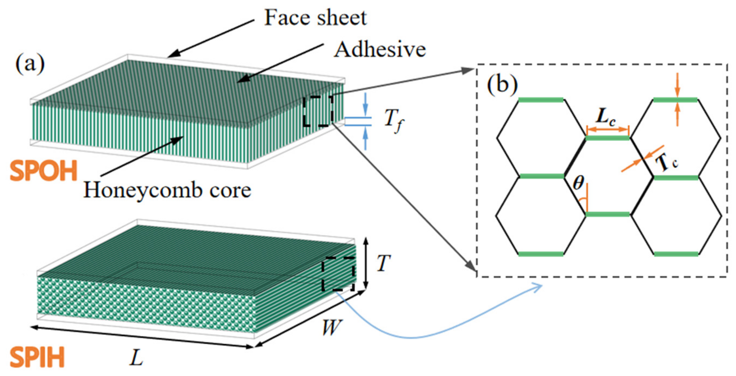
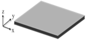
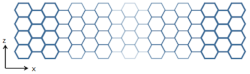
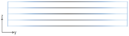
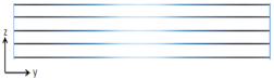
The sandwich panel is formed by a lightweight core and two face-sheets [37,38,39], as shown in Figure 1. The three overall dimensions for sandwich panels are the width , length , and thickness . The studied sandwich panel has two face-sheets with the same thickness . The honeycomb cells are regular hexagonal, and each cell is governed by core height , cell length , and single-wall thickness . Considering the processing technology of honeycomb, each unit of the core has four single walls and two bounded double walls in the manufacturing.
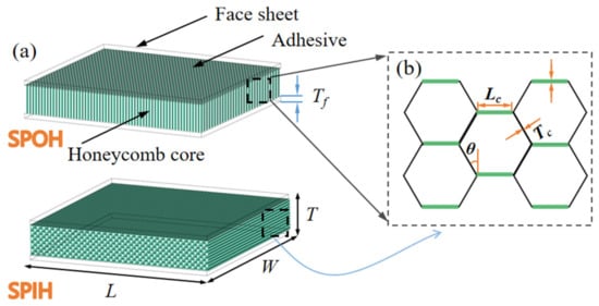
Figure 1.
(a) Schematic of SPOH and SPIH; (b) geometric parameters of honeycomb cells.
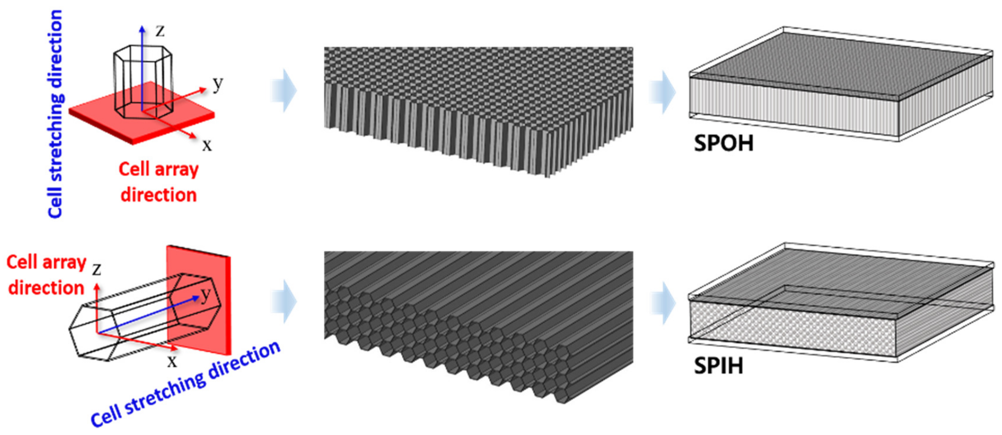
Two types of sandwich panels are considered in this study: sandwich panels with out-of-plane honeycombs (SPOH) and sandwich panels with in-plane honeycombs (SPIH). Figure 2 illustrates the structures of SPOH and SPIH. The cell stretching direction of the SPOH is vertical to face-sheets. Differently, for SPIH, the cell stretching direction is parallel to face-sheets.
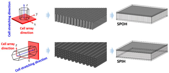
Figure 2.
Structures of SPOH and SPIH.
3. Finite Element Model Validation
3.1. The FE Model
Finite element (FE) simulation is conducted in ABAQUS/Explicit. The parameters of each component of the sandwich panel are shown in Table 1. The sandwich specimens used in this study were fabricated with aluminum alloy face-sheets (AA5052-O) and honeycomb cores (AA3003-H18) [28]. Face-sheets were meshed by the 8-node brick elements with reduced integration (C3D8R). Honeycomb core was explicitly modelled using the 4-node shell elements with reduced integration (S4R). The impactor is simulated by a spherical rigid body. The thickness of the adhesive layer is 0.3 mm and is tied with the honeycomb core. To simulate the impact damage behavior, the distribution of shear strain values of face-sheets, honeycomb, and adhesive layer are set as 0.55, 0.4, and 0.02, respectively. The boundary of the sandwich panel is fixed. The general contact algorithm was adopted to define the contact between different parts and self-contact behaviors. The “hard contact” is used in the normal direction. In the tangential direction, penalty contact is used, and the friction coefficient is defined as 0.2 [16]. Moreover, in order to improve the calculation efficiency, a quarter model is used for modeling, and symmetrical constraints are imposed.

Table 1.
Material parameters for each component of sandwich panels [28].
As shown in Table 2, the Johnson–Cook model was used to define the nonlinear behavior of plastic metallic materials under dynamic impact.
Table 2.
Material parameters of the Johnson–Cook model [28].
This material model takes into account the effects of strain rate, strain hardening, and thermal softening. The yield stress can be calculated as:
where is the von mises equivalent flow stress, is the equivalent plastic strain, is the equivalent plastic strain rate, and and are the material parameters representing the effect of strain rate. , , , and are the material parameters measured at or below the transition temperature, and is the non-dimensional temperature for considering the heat effect.
3.2. FE Model Calibration
In this study, air cannon impact testing is used to validate the accuracy of the FE model; the testing setup is shown in Figure 3. Sandwich panels with out-of-plane honeycombs have been prepared as specimens in this test. The geometric parameters used for the tested sandwich specimens are listed in Table 3, where is the impact speed. The sandwich panels are cut into square specimens with overall dimensions of 150 mm × 150 mm for the following air cannon impact tests. Each face-sheet is fabricated with a thickness of 1 mm. The three determining geometric parameters of the out-of-plane honeycomb cores used in this test are 4 mm in cell length, 0.06 mm in cell wall thickness, and 15 mm in cell height.
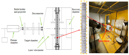
Figure 3.
Air cannon impact testing setup.
Table 3.
Specification of experimental specimens.
Figure 4 shows the damage modes of specimens under different impact velocities (40 m/s and 100 m/s). It can be seen that the numerical results are in good agreement with the air cannon impact testing results. Figure 5 shows the data between test and simulation and errors are at a low level (within 3%). These outcomes indicate that the numerical method can predict the experimental results well.
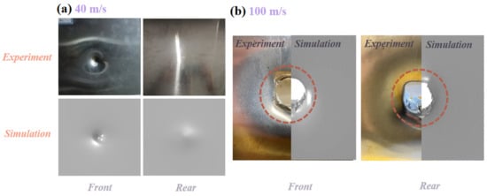
Figure 4.
Tested and simulated damage modes of specimens under (a) 40 m/s and (b) 100 m/s impact.
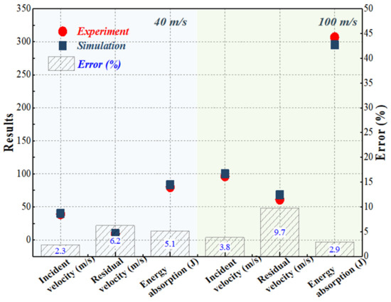
Figure 5.
Comparison between the tested and simulated data in terms of incident speed, residual speed, and energy absorption.
4. Results and Discussions
4.1. Comparison between SPIH and SPOH
4.1.1. Modes Characterization
A comparable diagram in terms of the impact modes between SPOH and SPIH is presented in Figure 6a.
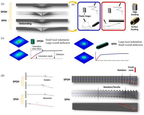
Figure 6.
Comparison on the deformation modes of SPOH and SPIH: (a) modes identifications; (b) cell array effect on the buckling behaviors; (c) overall bending behavior; (d) modes evolution with different plastic hinges formation.
For comparison of deformational behavior of SPOH and SPIH, impact parameters given in Table 4 are used.
Table 4.
Specification of the tested sandwich specimens.
It is observed that the indentation depth and deformation area of SPIH are significantly larger than those of SPOH. To further reveal the mechanism that produces this difference, the deformation patterns of honeycomb cells are compared in Figure 6b. According to Figure 6b, the out-of-plane honeycomb core is dominated by the folding of the cell wall. For the in-plane honeycomb, due to its orthogonal anisotropy, there are two typical deformation modes: the rotation of plastic hinge at the vertex of cell and the bending and stretching in the overall stretching direction of honeycomb. In contrast, the in-plane honeycomb has lower compressive strength and its configuration is favorable for the co-deformation of cells.
In Figure 6b, by comparing the displacement contours of the front and rear face-sheet, it can be found that although the indentation depth of the front face-sheet of SPIH is larger, the maximum displacement of the rear face-sheet is smaller. Homogeneous solid lines are used to replace the cross-section of the sandwich panels to clearly show the difference in the response patterns of SPOH and SPIH. In contrast, SPIH has larger indentation and less deflection. The indentation is mainly derived from the compression of the honeycomb core and the tension of the front face-sheet, while the deflection is mainly due to the overall behavior of the sandwich panel. Therefore, the deformation mode of SPIH is more conducive to resist the displacement of the rear face-sheet.
As shown in Figure 6d, it can be considered that the deformation of the sandwich panel in the cross-section is controlled by two plastic hinges, which are located at the boundaries of the indentation zone and the flexure zone, respectively. During the entire impact history, the plastic hinge in the flexure zone of SPOH is dominated by rotation. For the SPIH, the plastic hinge in the flexure zone has a significant movement to the distal end of the impact while rotating. Benefiting from the cooperative deformation of the cells of in-plane configuration, this movement not only can reduce deflection, but also mobilize more areas to participate in energy absorption.
4.1.2. Mode-Related Impact Characteristic
To clarify the relevance between the impact resistance and deformation modes, impact histories in terms of different sandwich panels are presented in Figure 7.
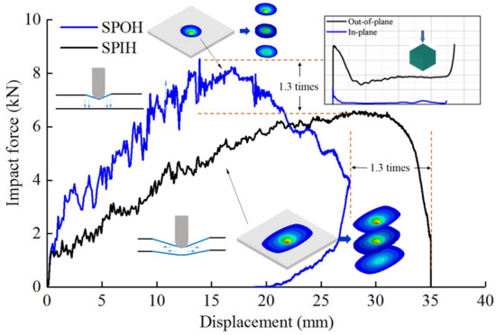
Figure 7.
Load–displacement histories of SPOH and SPIH at an impact speed of 83 m/s.
From the subsidiary in Figure 7, the comparison on crushing forces in terms of in-plane and out-of-plane honeycombs blocks is firstly conducted. There is an order of magnitude difference between the in-plane honeycomb and the out-of-plane honeycomb on the crushing force. However, a relatively small divergence on the impact forces of SPIH with in-plane honeycomb core and SPOH with out-of-plane honeycomb core can be observed in Figure 7. In other words, the impact resistance of the sandwich panel is not directly determined by the core compression strength.
In Figure 7, the area where the sandwich panel is displaced by more than 1 mm in the impact direction is represented by a colored stress contour. The area with displacement less than 1 mm is shown in gray, and it can be considered that this part does not contribute much to energy absorption [1]. Obviously, the effective energy absorption area of SPIH is much larger. Combined with the mode characterization in Figure 6, the reason why the impact force of SPIH is close to that of SPOH can be further explained. On the one hand, SPIH obviously extents the indentation profile which results in a more obvious tensile behavior of front face-sheet; on the other hand, when subjected to bending moments, the in-plane honeycomb will stretch in the direction of membrane stress instead of the cell shearing in that of out-of-plane honeycomb, which can provide an additional bending stiffness.
In addition, it is worth noting that the SPIH’s impact force curve rises more smoothly, with less fluctuation, and has a longer impact stroke. For energy absorbing structures, this feature has better protective properties.
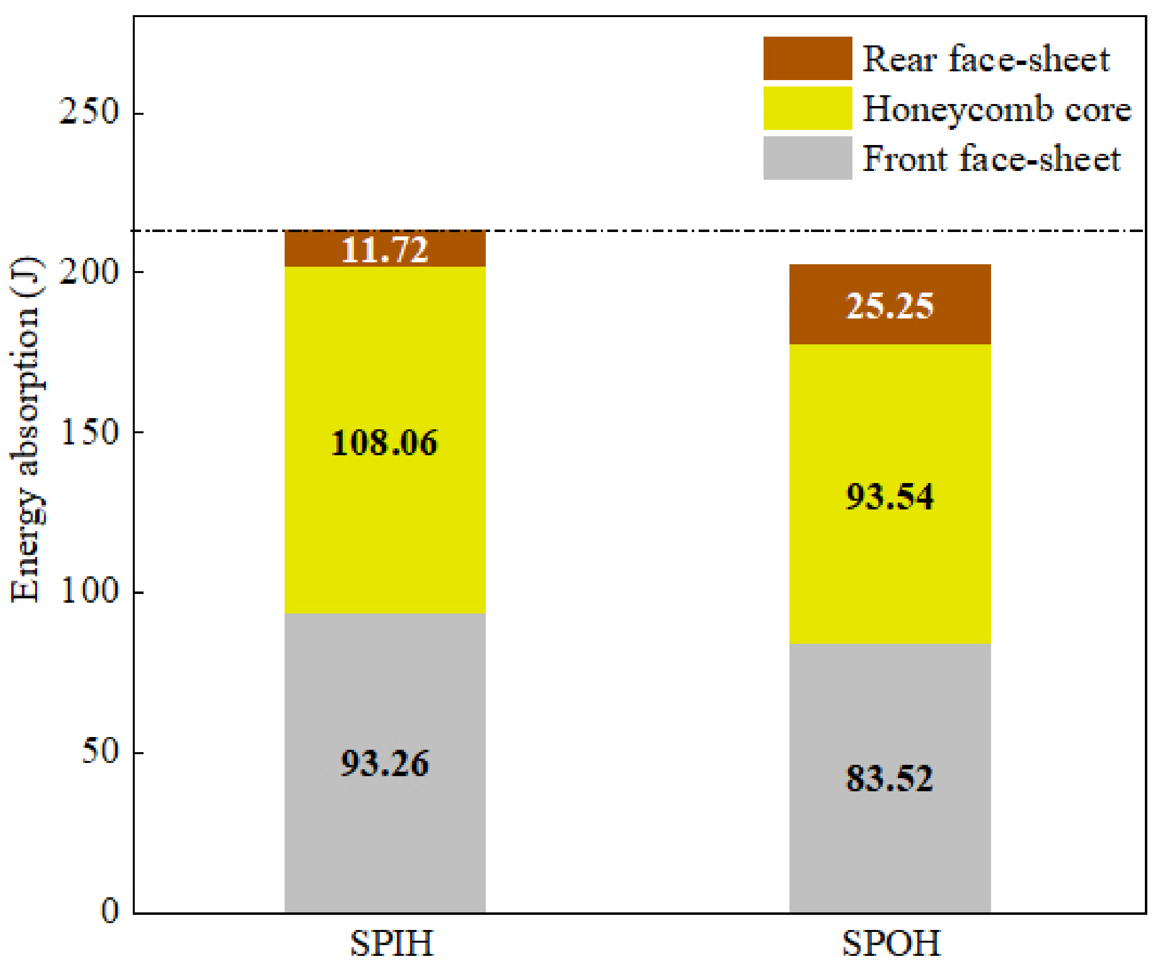
Figure 8 compares the energy absorption of different parts of the sandwich panel. SPIH showed a higher energy absorption effect. Not only that, the energy absorption of the front panel and honeycomb core of SPIH is greater than that of SPOH, while the energy absorption of the rear panel is only 46% of that of SPOH. This also confirms the analysis in Section 4.1.1 that SPIH can better protect the rear face-sheet by mobilizing the front face-sheet and honeycomb core to participate in energy absorption.
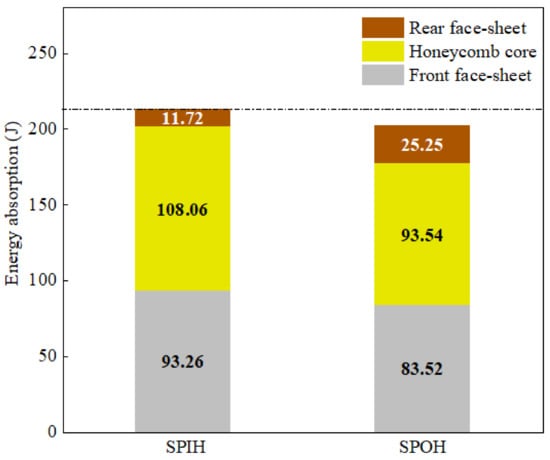
Figure 8.
Energy absorption of SPOH and SPIH at an impact speed of 83 m/s.
4.2. Effect of Impact Speeds and Impactor Radius
4.2.1. Modes Characterization
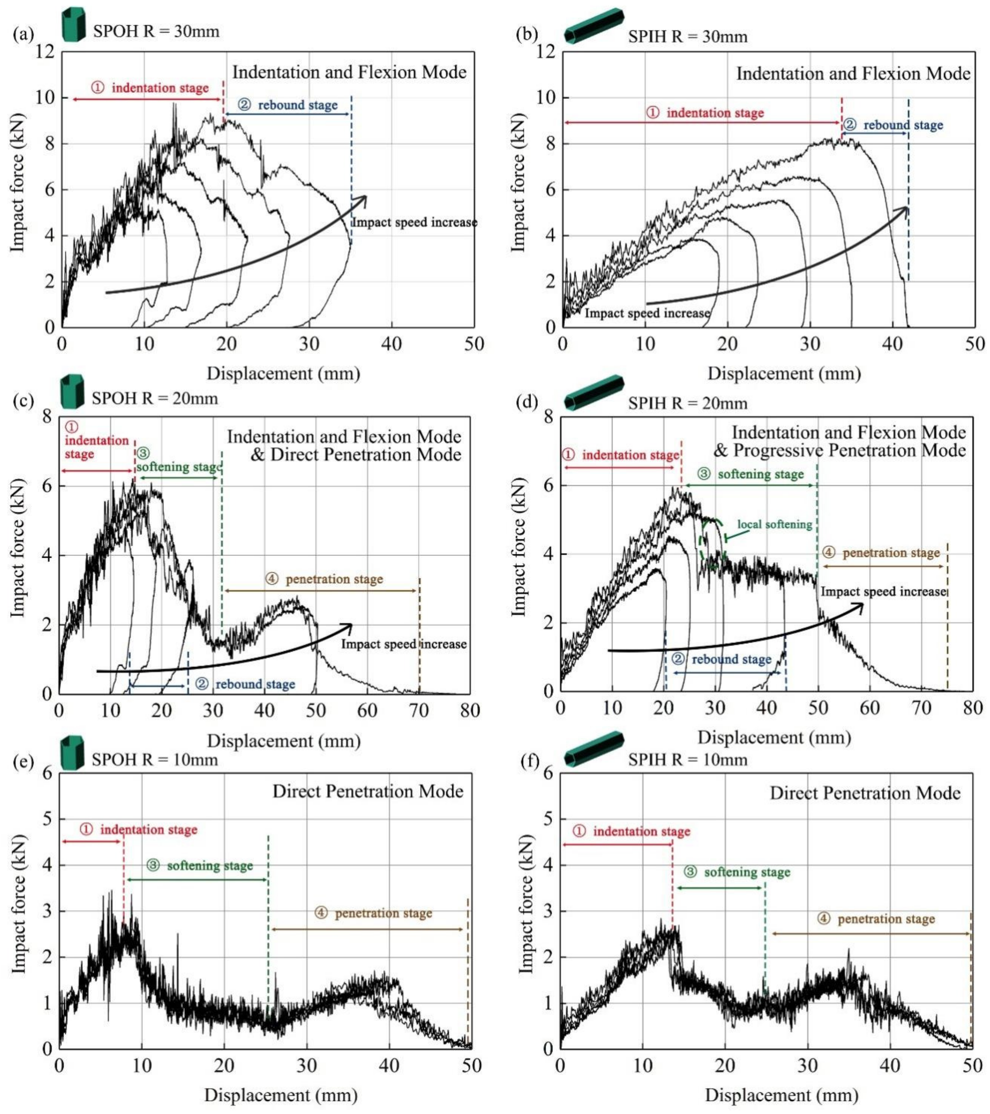
In this section, the structural response characteristics of SPOH and SPIH under different impactor radius and impact speed are compared. As shown in Figure 9, the radius of the impactor is set to 10 mm, 20 mm, and 30 mm, and each radius covers five speed levels of 44 m/s, 55 m/s, 70 m/s, 83 m/s, and 100 m/s. Figure 9a,b show the force–displacement curves when the radius of the impactor is 30 mm. Under these conditions, the impact response can be divided into indentation stage and rebound stage. In the indentation stage, with the increase in the impactor displacement, the impact force gradually increased. However, as the kinetic energy dissipates, the impact speed drops and the impact force starts to fall. Finally, the impactor rebounds. Throughout the impact process, all the sandwich panels show indentation and deflection mode. Note that SPIH has a longer indentation phase and less springback. This shows that the energy absorption process of SPIH is smoother when it is subjected to local impact, which is consistent with the conclusion in Section 4.1.
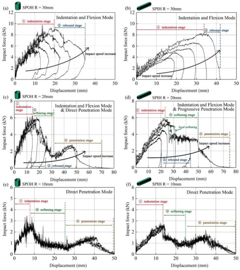
Figure 9.
Force–displacement curves of sandwich panels under different impact conditions. (a) The force–displacement curve of SPOH when the impactor radius is 30 mm. (b) The force–displacement curve of SPIH when the impactor radius is 30 mm. (c) The force–displacement curve of SPOH when the impactor radius is 20 mm. (d) The force–displacement curve of SPIH when the impactor radius is 20 mm. (e) The force–displacement curve of SPOH when the impactor radius is 10 mm. (f) The force–displacement curve of SPIH when the impactor radius is 10 mm.
Figure 9c,d further compare the response characteristics of the sandwich panel when the impactor radius is 20 mm. SPOH and SPIH still behave as indentation and deflection modes when the speed is 44 m/s, 55 m/s, and 70 m/s. When the impact speed was increased to 83 m/s, a softening stage was observed. At this stage, the load-bearing capacity of the sandwich panel is reduced due to the failure of the front face-sheet. Thus, the impact force drops sharply. In Figure 9c, after the softening stage of SPOH, the impact force drops directly to a very low level until it enters the penetration stage. The penetration stage indicates that the impactor has broken down the front face-sheet and the honeycomb core. At this time, the rear face-sheet begins to produce large plastic deformation, causing a slight increase in the impact force, but it will eventually fall again due to the penetration of the rear face-sheet. Different from SPOH, the impact force of SPIH still maintains a high plateau region after local softening. It can be explained as follows: when the out-of-plane honeycomb is compressed, axial folding and crushing occurs, while the deformation mode of the in-plane honeycomb is dominated by in-plane densification and axial stretching. Therefore, after the upper panel is damaged, the SPIH can still maintain good bearing capacity and energy absorption characteristics. It can be found that under the impact speed of 83 m/s, the SPIH only shows local softening, but does not enter the penetration stage. Additionally, when the speed is 100 m/s, although SPIH has the same penetration stage as SPOH, it can still maintain a period of impact platform before penetration. There were significant differences between the two response modes, and SPIH had better resistance to penetration. The mode of SPOH can be defined as direct penetration mode, while the mode of SPIH can be defined as progressive penetration mode.
According to Figure 9e,f, when the radius of the impactor is reduced to 10 mm, the sensitivity between the response mode and the impact speed is not significant. The force–displacement curves approximately coincide. In this case, both SPIH and SPOH behave as direct penetration mode.
The response modes of the sandwich panel under different impact conditions are sorted out, as shown in Figure 10. It demonstrates that the size effect of sandwich panels under localized impact is significant. Penetration behavior is more likely to occur when the radius of the impactor decreases. On the one hand, due to the more concentrated load, the effective energy absorption area of the sandwich panel is reduced. On the other hand, because of the smaller radius of the impactor, the local curvature of the face-sheet increases, and necking fracture is more likely to occur. Overall, SPIH has an advantage in resisting penetration.
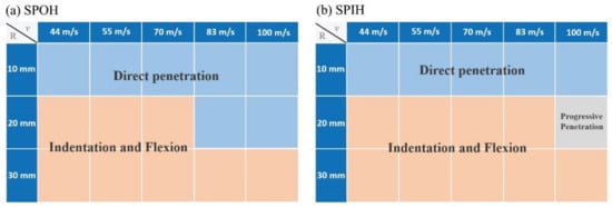
Figure 10.
Mode characterization maps of SPOH and SPIH. (a) Mode characterization maps of SPOH; (b) Mode characterization maps of SPIH.
4.2.2. Mode-Related Impact Characteristic
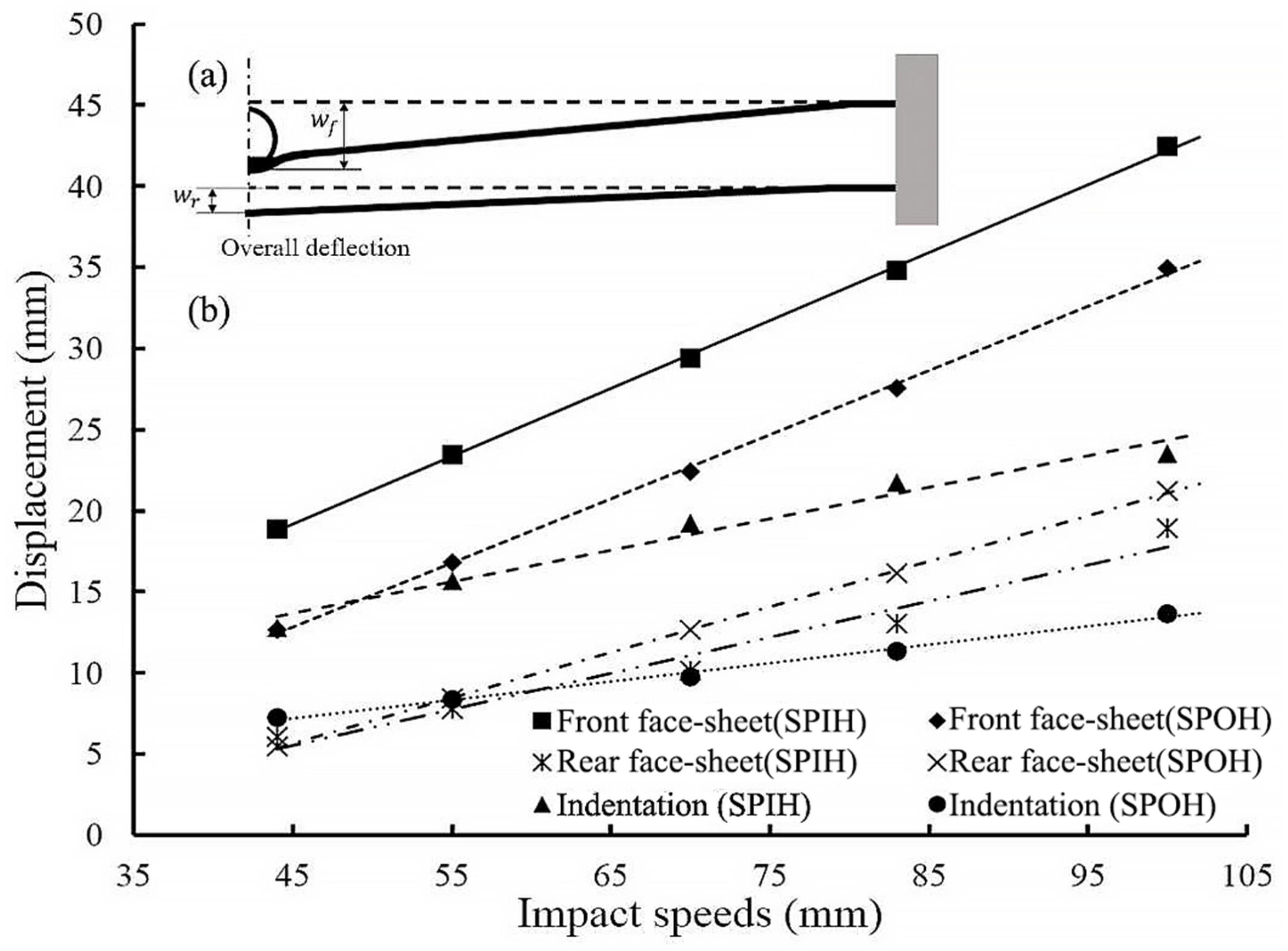
When the sandwich panel is at indentation and deflection mode, the impactor is not enough to penetrate the sandwich panel. In these cases, the overall deflection can be used as an evaluation index for impact resistance, as shown the Figure 11a.

Figure 11.
Mode characterization maps of sandwich panels under different loading conditions. (a) Schematic diagram of indentation and deflection of sandwich panels. (b) Displacement of face-sheets and indentation depth of sandwich panels.
represents the maximum displacement of the front face-sheet and represents the maximum displacement of the rear face-sheet. Thus, the indentation depth can be calculated as:
Among them, can also represent the total deflection of the sandwich panel.
Figure 11b quantitatively compares the deformation of SPOH and SPIH when the impactor radius is 30 mm. In the impact speed range of 44~100 m/s, SPIH always has a larger indentation depth and a smaller overall deflection. Additionally, as the speed increases, the difference becomes more pronounced. It indicates that under the impact of higher speed, SPIH can better reflect the advantage of resisting deformation.
For the case of penetration, the energy absorption of the sandwich panel and the residual velocity of the impactor can be used as evaluation indicators. TEA (total energy absorption) and SEA (specific energy absorption) are often used to evaluate the energy absorption effect of structures [40,41,42]. TEA refers to the total energy absorption of the structure. SEA is the ratio of TEA to mass. In this study, SHOP and SHIP have the same total quality. Therefore, it is feasible to only use TEA as an indicator. TEA can be used for comparison as follows:
where is the displacement of the impactor, and is the displacement when fully penetrated. The residual velocity can be calculated as follows:
where and are initial kinetic energy and impactor mass, respectively.
Table 5 and Table 6 compare the TEA of the sandwich panel and the of the impactor under penetration conditions. Overall, SPIH shows better impact characteristics in terms of energy absorption and residual velocity. Especially when the impact object radius is 20 mm and the impact speed is 100 m/s, the improvement is the most significant. As shown in Figure 11, when the impact object radius is 20 mm and the impact speed is 83 m/s, SPOH behaves as a direct penetration mode, while SPIH is in indentation flexure mode and progressive penetration mode. According to the discussion in Section 4.1 and Section 4.2.1, the response mode of SPIH is not only conducive to expanding the effective energy absorption area, but also extends the energy absorption stroke, which thus leads to a huge difference in energy absorption. When the impact speed is 100 m/s, the increase reaches 59.79%. However, it is noted that both SPOH and SPIH are in direct penetration mode when the impactor radius is 10 mm. In this case, SPIH’s advantages are not significant. It reveals that the impact characteristics of the sandwich panel are strongly correlated with the mode characteristics.
Table 5.
Specification of the tested sandwich specimens in terms of TEA.
Table 6.
Specification of the tested sandwich specimens in terms of .
5. Gradient Design
5.1. Gradient Design
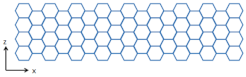
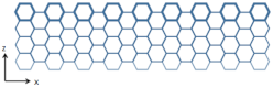
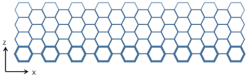
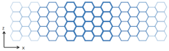
Compared to SPOH, SPIH showed improved performance in impact mitigation and energy absorption. To further tap its potential, different density gradient designs are carried out for SPIH in this section. The in-plane honeycomb exhibits anisotropy in three orthogonal directions, and combined with the two design concepts of positive and negative gradients, a total of six schemes are formed as shown in Table 7. The three gradient directions are loading direction (LD), cell array direction (AD), and cell stretching direction (SD). Positive and negative gradients are represented by the letters P and N, respectively. The positive gradient indicates a high density of core close to the impact location (dark color as shown in Table 7); the negative gradient indicates a low density of core close to the impact location (light color as shown in Table 7). A linearly varying continuous gradient is achieved by varying the honeycomb wall thickness. At the same time, to ensure comparability, different schemes maintain the same relative density.
Table 7.
Schematic of the density gradient of the core in three directions for SPIH.
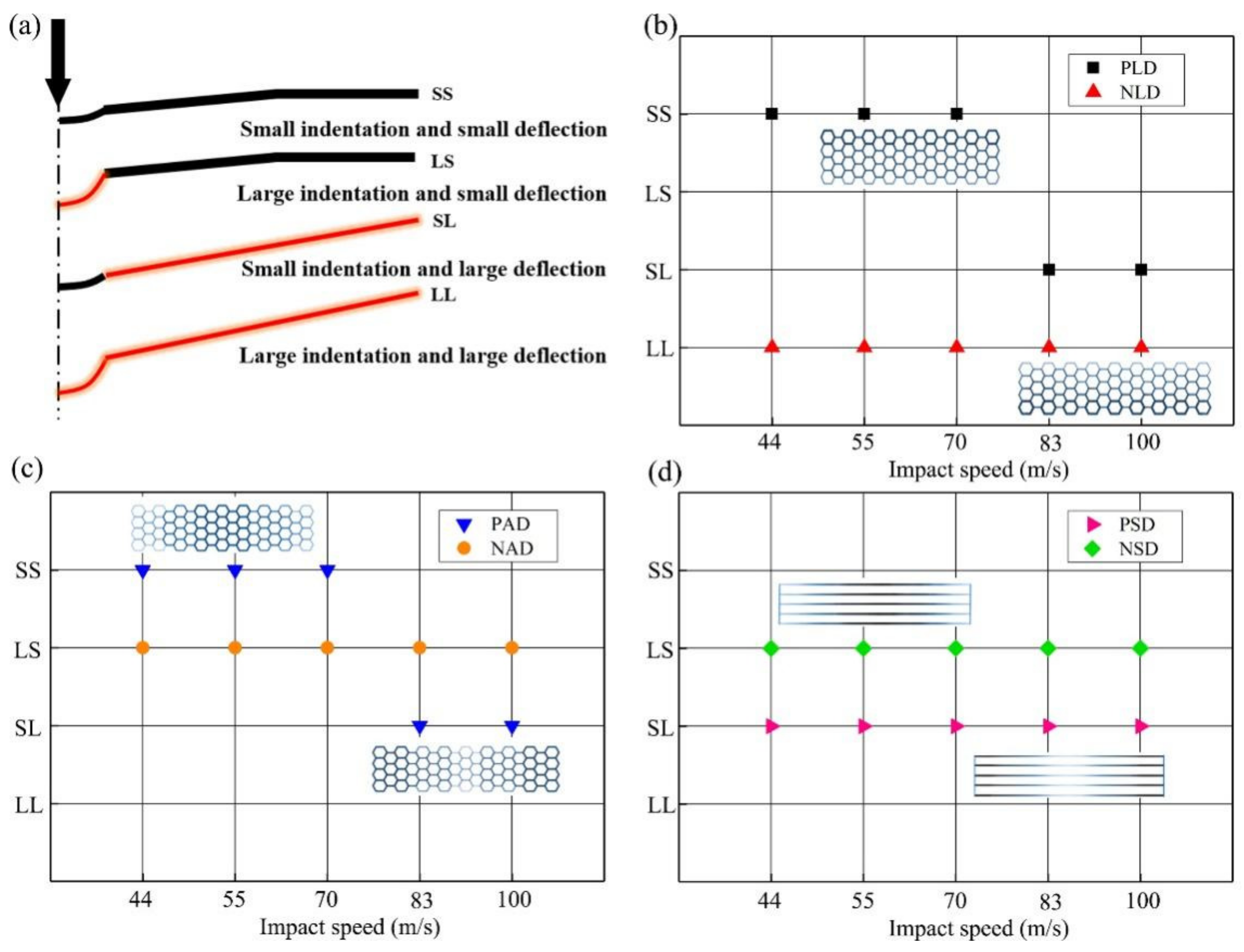
5.2. Modes Characterization
As shown in Figure 12a, four deformation modes are defined according to the indentation depth and overall deflection of the sandwich panel, labelled as SL, SS, LL, and LS. Note that large and small here represent the relative results between gradient and non-gradient honeycombs. By comparing the change of indentation depth, all the positive gradient designs in three orthogonal directions can reduce the indentation. In order to suppress the overall deflection, PLD, PAD, NAD, and NSD are recommended under low-medium speed impact (44~70 m/s). Under high-speed impact (83~100 m/s), NAD and NSD are recommended. Note that PLD and PAD can reduce the deflection at low-medium speed but aggravate the overall deformation at high-speed impact. It can be explained as follows. Under dynamic impact, the sandwich panels have inertial effect. Thanks to the positive gradient design, more kinetic energy can be dissipated in the early stage of impact, thus reducing the overall deflection. However, when the impact kinetic energy is large and the plastic deformation spreads to the area with weak strength, the overall deflection will increase.
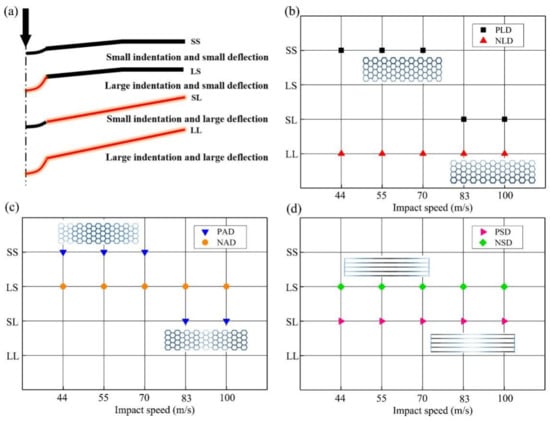
Figure 12.
(a) Schematic of different overall bending modes. (b) The deformation modes of PLD and NLD. (c) The deformation modes of PAD and NAD. (d) The deformation modes of PSD and NSD.
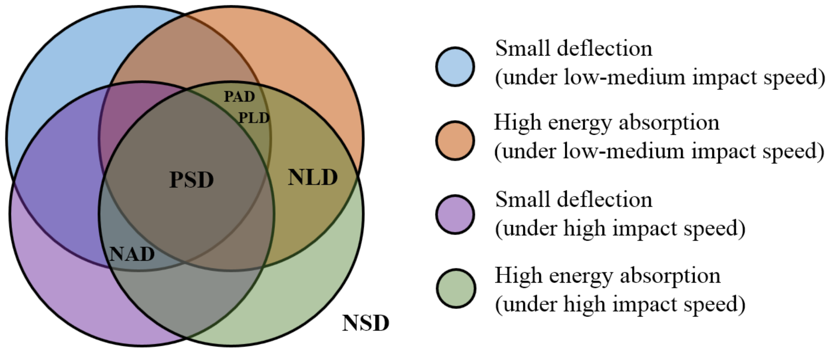
5.3. Mode-Related Impact Characteristic
Combining deflection index and energy absorption index, functional maps can be obtained. As shown in Figure 13, the four circles correspond to the functional characteristics of different impact speeds. The intersection of the circle indicates that the structure falling in this interval has many advantageous properties. According to Figure 13, although NLD can improve the energy absorption, it will lead to the increase in the rear face-sheet displacement. PAD and PLD can give consideration to the advantages of small deflection and high energy absorption under medium- and low-speed impact. The NAD design is beneficial to resist the overall deformation. However, it only shows the advantage of energy absorption at high-speed impact. In contrast, PSD has the best comprehensive performance. At different impact speeds, it can resist the overall deflection and improve the energy absorption effect.
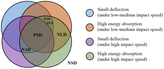
Figure 13.
Functional maps of gradient sandwich panels.
6. Conclusions
The performances of traditional sandwich panels (with out-of-panel honeycombs) SPOH and of sandwich panels proposed in the given study (with in-panel honeycombs) SPIH are investigated under various impact velocities. Furthermore, the impact mitigation capacities of SPIH with different density gradient cores are also considered. Some conclusions can be drawn below:
- Compared with SPOH, SPIH shows better energy absorption protection effect under different impact loads. The use of in-plane honeycomb core is not only beneficial to reduce the overall deflection, but also significantly improves the energy absorption. When the sandwich planes are not penetrated (with impact radius 20 mm and impact speed 83 m/s), the maximum displacement of SPIH rear face-sheet is reduced by 30.12% compared with SPOH. When the sandwich panels are penetrated (with impact radius 20 mm and impact speed 83 m/s), the TEA of SPIH is 158.89 J, and the TEA of SPOH is 200.18 J. In contrast, SPIH’s energy absorption increased 59.79%.
- There is an order of magnitude difference between the in-plane strength and the out-of-plane strength of honeycomb. However, under local impact, the difference in impact peak force between SPIH and SPOH is relatively small. When the impact radius is 30 mm and the impact speed is 100 m/s, the peak contact force of SPIH is only 10% less than that of SPOH. It shows that the impact resistance of sandwich panel is not directly determined by the core compression strength. The response mode also has a significant effect.
- The size effect is significant when the sandwich panels are subjected to local impact. A smaller impactor radius is more likely to cause penetration. The indentation flexion mode, direct penetration mode, and progressive penetration mode are three typical characteristic modes. The progressive penetration mode is unique to SPIH, which greatly improves the energy absorption under penetration conditions.
- Through the gradient design of SPIH, the impact resistance characteristics under different load conditions can be optimized. The different gradient schemes enable sandwich panels to perform multiple functions. In general, PSD is recommended to reduce the overall deflection and increase the energy absorption.
Author Contributions
J.L.: funding acquisition, conceptualization, investigation, data curation, and writing—original draft. G.W.: methodology, validation, and writing—review and editing. Z.L.: methodology, formal analysis, writing—original draft, and writing—review and editing. All authors have read and agreed to the published version of the manuscript.
Funding
This work was financially supported by The Independent Funds of State key laboratory of high performance complex manufacturing (ZZYJKT2020-05); The CHINA Postdoctoral Science Foundation (2022M713515). The authors would like to express their gratitude.
Institutional Review Board Statement
Not applicable.
Informed Consent Statement
Not applicable.
Data Availability Statement
Data available on request from the authors.
Conflicts of Interest
No potential conflict of interest was reported by the authors.
References
- Liu, J.; Chen, W.; Hao, H.; Wang, Z. In-plane crushing behaviors of hexagonal honeycombs with different Poisson’s ratio induced by topological diversity. Thin-Walled Struct. 2021, 159, 107223. [Google Scholar] [CrossRef]
- Wang, Z.; Liu, J. Numerical and theoretical analysis of honeycomb structure filled with circular aluminum tubes subjected to axial compression. Compos. Part B Eng. 2019, 165, 626–635. [Google Scholar] [CrossRef]
- Pydah, A.; Batra, R. Blast loading of bumper shielded hybrid two-core Miura-ori/honeycomb core sandwich plates. Thin-Walled Struct. 2018, 129, 45–57. [Google Scholar] [CrossRef]
- Hou, W.; Shen, Y.; Jiang, K.; Wang, C. Study on mechanical properties of carbon fiber honeycomb curved sandwich structure and its application in engine hood. Compos. Struct. 2022, 286, 115302. [Google Scholar] [CrossRef]
- Liu, D.; Zhou, W.; Lu, Z.; Gu, H.; Li, T.; Zhong, M. Effect of car-body initial dynamic sway on overturning before high-speed trains negotiate wind speed variations. Veh. Syst. Dyn. 2021, 60, 2451–2468. [Google Scholar] [CrossRef]
- Liu, D.; Li, T.; Lu, Z.; Chen, J.; Zhong, M. Experimental–numerical investigation of momentary discomfort in a high-speed train in varying wind speed conditions. Veh. Syst. Dyn. 2020, 60, 1440–1459. [Google Scholar] [CrossRef]
- Tao, Q.; Ren, P.; Shi, L.; Zhao, Z.; Tang, Y.; Ye, R.; Zhang, W.; Cui, J. Energy absorption and impact behavior of composite sandwich panels under high-speed spherical projectile. Int. J. Impact Eng. 2022, 162, 104143. [Google Scholar] [CrossRef]
- Liu, J.; Wang, Z.; Hui, D. Blast resistance and parametric study of sandwich structure consisting of honeycomb core filled with circular metallic tubes. Compos. Part B Eng. 2018, 145, 261–269. [Google Scholar] [CrossRef]
- Sun, G.; Chen, D.; Huo, X.; Zheng, G.; Li, Q. Experimental and numerical studies on indentation and perforation characteristics of honeycomb sandwich panels. Compos. Struct. 2018, 184, 110–124. [Google Scholar] [CrossRef]
- Xu, J.; Fu, C.; Fu, Q.; Chen, Y.; Feng, X. Flexible arc-armor inspired by origami. Int. J. Mech. Sci. 2021, 201, 106463. [Google Scholar] [CrossRef]
- Liu, J.; Dong, Z.; Zhu, X.; Sun, W.; Huang, Z. Flexural properties of lightweight carbon fiber/epoxy resin composite sandwiches with different fiber directions. Mater. Res. Express 2022, 9, 10. [Google Scholar] [CrossRef]
- Wang, H.; Ramakrishnan, K.; Shankar, K. Experimental study of the medium speed impact response of sandwich panels with different cores. Mater. Des. 2016, 99, 68–82. [Google Scholar] [CrossRef]
- Li, Z.; Chen, W.; Hao, H.; Yang, Q.; Fang, R. Energy absorption of kirigami modified corrugated structure. Thin-Walled Struct. 2020, 154, 106829. [Google Scholar] [CrossRef]
- Tang, J.; Zhou, Z.; Chen, H.; Wang, S.; Gutierrez, A.; Zhang, C.; Deng, J. Laminate design, optimization, and testing of an innovative carbon fiber-reinforced composite sandwich panel for high-speed train. Polym. Compos. 2021, 42, 5811–5829. [Google Scholar] [CrossRef]
- Xiang, C.; Qin, Q.; Wang, M.; Yu, X.; Chen, S.; Zhang, W.; Xia, Y.; Zhang, J.; Zhao, J.; Wang, T. Low-speed impact response of sandwich beams with a metal foam core: Experimental and theoretical investigations. Int. J. Impact Eng. 2019, 130, 172–183. [Google Scholar] [CrossRef]
- Wang, Z.; Lu, Z.; Yao, S.; Zhang, Y.; Hui, D.; Feo, L. Deformation mode evolutional mechanism of honeycomb structure when undergoing a shallow inclined load. Compos. Struct. 2016, 147, 211–219. [Google Scholar] [CrossRef]
- Liu, J.; Chen, W.; Hao, H.; Wang, Z. Numerical study of low-speed impact response of sandwich panel with tube filled honeycomb core. Compos. Struct. 2019, 220, 736–748. [Google Scholar] [CrossRef]
- Zhang, W.; Yan, L.; Zhao, X.; Su, P.; Lu, T. Enhancement Effect and Energy Absorption of Double-Layer Metallic Lattice Structure Filled with Aluminum Foam. Rare Met. Mater. Eng. 2019, 48, 3911–3916. [Google Scholar]
- Lv, W.; Li, D.; Dong, L. Study on blast resistance of a composite sandwich panel with isotropic foam core with negative Poisson’s ratio. Int. J. Mech. Sci. 2021, 191, 106105. [Google Scholar] [CrossRef]
- Ha, N.; Lu, G. A review of recent research on bio-inspired structures and materials for energy absorption applications. Compos. Part B Eng. 2020, 181, 38. [Google Scholar] [CrossRef]
- Felipe, D.; Ferreira, G.; Carlos, A.; Da, C.; Faria, B.; Morais, J. Experimental dynamic analysis of composite sandwich beams with magnetorheological honeycomb core. Eng. Struct. 2018, 176, 231–242. [Google Scholar]
- Xiang, J.; Du, J. Energy absorption characteristics of bio-inspired honeycomb structure under axial impact loading. Mater. Sci. Eng. A 2017, 696, 283–289. [Google Scholar] [CrossRef]
- Peng, H.; Du, J. Energy Absorption Characteristics of Bio-Inspired Honeycomb Column Thin-Walled Structure Under Impact Loading. J. Mech. Behav. Biomed. Mater. 2018, 79, 301. [Google Scholar]
- Zhang, L.; Bai, Z.; Bai, F. Crashworthiness design for bio-inspired multi-cell tubes with quadrilateral, hexagonal and octagonal sections. Thin-Walled Struct. 2018, 122, 42–51. [Google Scholar] [CrossRef]
- Alkbir, M.F.M.; Sapuan, S.M.; Nuraini, A.A.; Ishak, M.R. Fibre properties and crashworthiness parameters of natural fibre-reinforced composite structure: A literature review. Compos. Struct. 2016, 148, 59–73. [Google Scholar] [CrossRef]
- Chen, Y.; Fu, K.; Hou, S.; Han, X.; Ye, L. Multi-objective optimization for designing a composite sandwich structure under normal and 45° impact loadings. Compos. Part B Eng. 2018, 142, 159–170. [Google Scholar] [CrossRef]
- Usta, F.; Türkmen, H.; Scarpa, F. Low-speed impact resistance of composite sandwich panels with various types of auxetic and non-auxetic core structures. Thin-Walled Struct. 2021, 163, 107738. [Google Scholar] [CrossRef]
- Sun, G.; Chen, D.; Wang, H.; Hazell, P.J.; Li, Q. High-velocity impact behaviour of aluminium honeycomb sandwich panels with different structural configurations. Int. J. Impact Eng. 2018, 122, 119–136. [Google Scholar] [CrossRef]
- Sun, G.; Huo, X.; Wang, H.; Hazell, P.J.; Li, Q. On the structural parameters of honeycomb-core sandwich panels against low-speed impact. Compos. Part B Eng. 2021, 216, 108881. [Google Scholar] [CrossRef]
- Zhang, Y.; Zong, Z.; Liu, Q.; Ma, J.; Wu, Y.; Li, Q. Static and dynamic crushing responses of CFRP sandwich panels filled with different reinforced materials. Mater. Des. 2017, 117, 396–408. [Google Scholar] [CrossRef]
- Baran, T.; Ztürk, M. In-plane elasticity of a strengthened re-entrant honeycomb cell. Eur. J. Mech. A Solids 2020, 83, 104037. [Google Scholar] [CrossRef]
- Shen, J.; Ge, J.; Xiao, J.; Liang, J. In-plane impact dynamics of honeycomb structure containing curved reentrant sides with negative Poisson’s ratio effect. Mech. Adv. Mater. Struct. 2020, 29, 1489–1497. [Google Scholar] [CrossRef]
- Ma, Q.; Rejab, R.; Siregar, J.; Guan, Z. A review of the recent trends on core structures and impact response of sandwich panels. J. Compos. Mater. 2021, 55, 2513–2555. [Google Scholar] [CrossRef]
- Li, Z.; Yang, Q.; Chen, W.; Hao, H.; Fang, R.; Cui, J. Dynamic compressive properties of reinforced and kirigami modified honeycomb in three axial directions. Thin-Walled Struct. 2022, 171, 108692. [Google Scholar] [CrossRef]
- Li, S.; Liu, Z.; Shim, V.; Guo, Y.; Wang, Z. In-plane compression of 3D-printed self-similar hierarchical honeycombs—Static and dynamic analysis. Thin-Walled Struct. 2020, 157, 106990. [Google Scholar] [CrossRef]
- Wang, S.; Wang, R.; Xia, Y.; Sun, Z.; You, L.; Zhang, J. Multi-objective aerodynamic optimization of high-speed train heads based on the PDE parametric modeling. Struct. Multidiscip. Optim. 2021, 64, 1285–1304. [Google Scholar] [CrossRef]
- Saurabh, R.; Nikhil, K.; Gaurav, T. A comparative study on the ballistic performance of aramid and aluminum honeycomb sandwich structures. Compos. Struct. 2022, 299, 116048. [Google Scholar]
- Li, Y.; Wu, X.; Xiao, W.; Wang, S.; Zhu, L. Experimental study on the dynamic behaviour of aluminium honeycomb sandwich panel subjected to ice wedge impact. Compos. Struct. 2022, 282, 115092. [Google Scholar] [CrossRef]
- Li, Y.; Lv, Z.; Wang, Y. Blast response of aluminum foam sandwich panel with double V-shaped face plate. Int. J. Impact Eng. 2020, 144, 103666. [Google Scholar] [CrossRef]
- Wang, Z.; Lei, Z.; Li, Z.; Yuan, K.; Wang, X. Mechanical reinforcement mechanism of a hierarchical Kagome honeycomb. Thin-Walled Struct. 2021, 167, 108235. [Google Scholar] [CrossRef]
- He, Q.; Feng, J.; Zhou, H. A numerical study on the in-plane dynamic crushing of self-similar hierarchical honeycombs. Mech. Mater. 2019, 138, 103–151. [Google Scholar] [CrossRef]
- Chen, Y.; Ye, L.; Fu, K. Progressive failure of CFRP tubes reinforced with composite sandwich panels: Numerical analysis and energy absorption. Compos. Struct. 2021, 263, 113674. [Google Scholar] [CrossRef]


Disclaimer/Publisher’s Note: The statements, opinions and data contained in all publications are solely those of the individual author(s) and contributor(s) and not of MDPI and/or the editor(s). MDPI and/or the editor(s) disclaim responsibility for any injury to people or property resulting from any ideas, methods, instructions or products referred to in the content. |
© 2023 by the authors. Licensee MDPI, Basel, Switzerland. This article is an open access article distributed under the terms and conditions of the Creative Commons Attribution (CC BY) license (https://creativecommons.org/licenses/by/4.0/).