Abstract
Magnetic gear and magnetic-geared machine (MGM) are the potential solutions in electric vehicles (EVs) powertrains for inherent high efficiency and mechanical simplification. However, the torque density issue of the MGM greatly limits its industrial application. To enhance the torque performance of the MGM, a torque-enhanced magnetic-geared machine with dual-series-winding and its design approach are proposed. The key merits of the proposed design are to achieve a high space utilization with a dual-winding design, with no additional control topologies and power converters required. The auxiliary winding is supplemented and integrated with modulation rings. The relative position of the stator and armature winding are designed and rotated compared to the modulation rings with auxiliary winding, to ensure the auxiliary winding shares the excitation with the armature winding. Accordingly, simplifying the external control topologies. With the proposed design, the torque of the MGM can be significantly enhanced with a single three-phase driving. Theoretical analysis, parameters optimization and electromagnetic verification are given, demonstrating that the proposed machine can achieve an efficiency of 93.2%, generate a torque of 107.2 N·m, and reach a torque density of 10.81 N·m/kg.
1. Introduction
Electric vehicles (EVs) have been developed and given rise to many novel technologies, including electric, hybrid, and hydrogen vehicles [1,2,3,4,5,6]. Regardless of iteration and deployment in the electric vehicle, the electric machines (EMs) are always the key and irreplaceable component of the powertrain system, which is a promising solution for developing green energy, making it a continued research trend in this decade [7]. In the electric vehicle propulsion system, the volume of the electric machine is inversely proportional to its nominal speed [8]. Hence, the propulsion system always employs a combination of a high-speed electric machine and a reduction mechanical gearbox. The magnetic-geared machine (MGM) combined the mechanical gearbox and the direct-drive EM into an integral machine, as one of the novel electric machines, which has been applied in electric vehicle propulsion [9,10,11,12] with inherent advantages of efficiency enhancement [13], noise reduction [14], and vibration attenuation [15]. However, generalized MGMs also have the inherent drawback of low torque density caused by poor space utilization with modulation rings. To solve the torque density issue, researchers proposed many solutions based on magnetic-geared topologies. According to the magnetized orientations of the permanent magnets (PMs), the solutions are mainly divided into axial flux MGMs and coaxial flux MGMs.
As for the coaxial flux MGMs, Ref. [13] optimizes the magnetic circuit design of spoke-type PMs with a slot-inserted structure, which improves the torque density. Reference [14] improves space utilization by installing the armature winding between the modulation rings without external drivings. However, the inherent contradiction of the design in [14] will restrict its performance, for the length of the modulation rings is proportional to the excitation current but inverse to the modulation effect of the magnetic gear. Refs. [15,16,17] investigate the integration of PMs and modulation rings, which improve the torque performance of the MGMs. However, the performance enhancement in torque or torque density is not significant. The torque improvement in Refs. [15,16] reach 8.05% and 6.58%, while the improvement in torque density of Ref. [17] is 5.35%. A double-stator single-rotor topology was proposed in Ref. [18] with a single modulation ring. The winding in the outer stator employs the modulation effect while another set of winding with the fractional-slot structure is without modulation rings. This design optimizes the performance of the dual stator MGM but the spaces between modulation rings are not fully utilized.
As for the axial flux MGMs, Ref. [19] reuses the modulation rings as stator slot to install the armature winding, which shares the design thought with [14] but together with its inherent drawbacks. Ref. [20] integrates and installs the electric machine in the bore of the axial flux magnetic gear, requiring no external volume. However, the design concept is similar to the coaxial flux MGMs and the spaces between modulation rings are not utilized properly.
As for the control strategy of the MGMs, ref. [21] proposes a maximum torque control strategy, verifying that the MGM can share the control strategy with generalized PM machines. Ref. [22] proposes a nonlinear position controller for MGM with improved tracking and disturbance rejection properties. A rotor position detection method for senseless control is proposed in Ref. [23], which verifies the feasibility of senseless control in MGMs. In general, MGMs can share the control strategies with generalized PM machines, providing strong generalization in EVs propulsion systems.
In this paper, to solve the abovementioned issue of the MGMs, a dual-series-winding (DSW) magnetic geared machine and its design approach are proposed. The main contribution of this paper is given as follows.
- (1)
- The torque and space utilization are enhanced with the proposed dual-series-winding design.
- (2)
- The design approach of the dual-series-winding is proposed and verified, which allows the auxiliary winding and armature winding to be driven by one set of three-phase inverter solely.
- (3)
- The relationship between the winding phase and mechanical rotation angle is given, investigating the impact of the relative position between modulation rings and stator, on the phase of the induced voltage.
2. Machine Configuration and Analysis
2.1. Machine Configuration
The overall structure of the proposed machine is indicated in Figure 1a while the parameters and the 3D cross-section are shown in Figure 1b, which consists of a stator integrated with modulation rings, armature winding, auxiliary winding, and rotor with surface-mounted permanent magnets (PMs). The detailed parameters of the proposed machine are given in Table 1. The fixed parameters include the non-physical parameters of the proposed machine except the outer diameter, stack length, and air gap length, which is selected for conducting a better optimization under a fixed size and topology of the proposed machine. As shown in Figure 1a, the modulator ring is combined with the stator, which eliminates the air gap between modulation rings and the stator, accordingly, enhances the mechanical stability of the MGMs. The distributed windings are employed in the armature winding with the pitch of 4 and auxiliary winding with the pitch of 3.
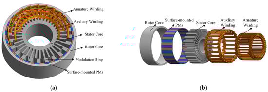
Figure 1.
Structure configuration of the proposed machine (a) 3-D and exploded view. (b) 3-D cross-section of machine components.

Table 1.
Fixed parameters of the proposed machine.
The winding configuration of the armature winding and auxiliary winding is given in Figure 2a,b, respectively. The A, B, C in Figure 2 represent the A, B, C phase of winding. For the winding configuration to be symmetrical, the configuration is presented with half of the slots. The detailed parameters of the proposed machine are given in Table 1. The changeable parameters are given and used to optimize the performance of the proposed machine in Section 3.
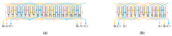
Figure 2.
Winding configurations. (a) Armature winding. (b) Auxiliary winding.
The powertrain system configuration of the electric vehicle with the proposed machine is given in Figure 3. As shown in Figure 3, the powertrain system consisted of the proposed machine, inverter, and power battery. The battery is charged by the power grid and corresponding AC-DC converter [24].
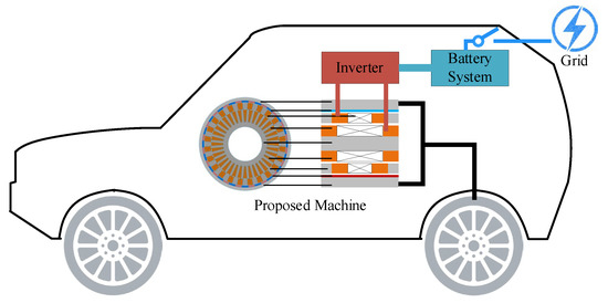
Figure 3.
Powertrain system configuration of the electric vehicle with the proposed machine.
2.2. Operating Principle
The pole pairs of the rotor PMs , modulation rings ,
and armature winding are 20, 24, and 4, respectively. The relationships [25] among them should follow Equation (1).
Based on Equation (1), the relationship between the angular velocity and pole pairs of those components is given as follows.
In this paper, , , and are the angular velocity of armature winding, modulation rings, and the rotor.
Considering the torque performance, the pole pairs of modulation rings are selected and equal to the summation of that of armature winding and rotor PMs [26]. Hence, the flux frequency of the armature winding and auxiliary winding under the mechanical rotating velocity (rp/m) is expressed as.
where the and is the flux frequency of armature winding and auxiliary winding, respectively.
Based on Equations (2) and (3), the flux frequency of those two sets of winding is equal, which built up the foundation of the proposed dual-series-winding design.
2.3. Dual-Series-Winding Design and Analysis
For a magnetic-geared machine with surface-mounted PMs, the magnetic motive force (MMF) generated by PMs, and permeance caused by modulation rings and stator teeth are shown in Figure 4. Based on Figure 4a, the Fourier series expansion of MMF generated by rotor PMs is expressed as Equation (4).
where is the n-th harmonics of the MMF generated by PMs.
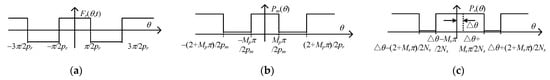
Figure 4.
The magnetic motive force and permeance of the proposed machine. (a) MMF generated by rotor PMs. (b) The permeance of modulation rings. (c) The permeance of stator teeth.
Similarly, the Fourier series expansion of the permeance of the modulation rings with the air gap and stator teeth can be concluded as Equations (5) and (6).
where and is the permeance of the modulation rings and stator tooth.
Hence, the flux density in the air gap can be found via Equations (4) and (5), which is given in Equation (7).
The order, amplitude, and angular velocity of harmonics of the flux density can be concluded in Table 2, which is based on Equation (7). The flux in stator tooth/modulation rings can be calculated with air gap area and magnetic induction intensity , which is shown as follows.
where r is the radius of the air gap and l is the length of the domain of integration. The area S equals the product of l, r and .
Table 2.
Modulated harmonics in air-gap.
Accordingly, as for the modulation rings, the flux in i-th modulation ring can be defined as Equation (9).
where is the radial of the outer air gap.
Based on Equation (9), the amplitude and the phase of flux in the i-th modulation ring can be found as follows.
As for the stator, the flux in the stator tooth can be found and the derivation is given as follows. When the stator and modulation rings are installed at the position shown in Figure 5, the flux in the first stator tooth is defined as follows.
where is the radial of the inner air gap.
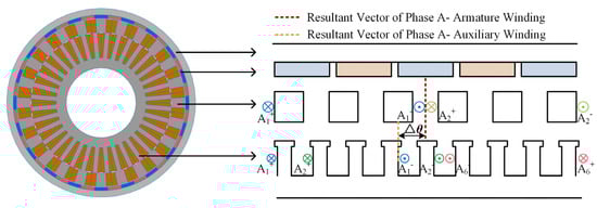
Figure 5.
Two-dimensional cross-section at average diameter and winding configuration of A phase of armature winding and auxiliary winding.
When the stator is rotated to the degree of , the flux in the first stator tooth is redefined as follows.
As indicated in Equations (11) and (12), when the stator is rotated by , the phase of flux in the stator tooth will vary with ( while the amplitude is unchanged. Moreover, the flux in the j-th stator tooth can be found in Equation (13).
Based on Equations (12) and (13), the phase difference between 1st and i-th tooth is . The fixed parameters of the proposed machine are given in Table 1. The phase angle of the 1st modulation ring is selected as the reference vector. is defined as the phase difference between 1st modulation ring of the auxiliary winding and 1st stator tooth of the armature winding, which is indicated in Figure 6.
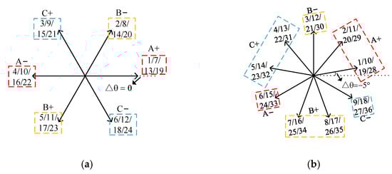
Figure 6.
Coil EMF phasors for the proposed machine. (a) Auxiliary winding. (b) Armature winding.
As shown in Figure 6 and Table 1, the pitch of the auxiliary winding and the armature winding is 3 and 4. Based on Equations (10) and (13), the phase of flux in the i-th modulation ring and the j-th stator tooth is concluded as follows.
Based on Equation (12) and Figure 5, the resultant vector of the A phase of the auxiliary winding is 60 deg, while that of the A phase of the armature winding is 4 + 80 deg. For ensuring the resultant vector of armature winding matches that of the auxiliary winding, the is selected as −5 deg.
3. Parameters Configuration and Optimization
To better confirm the superiority of the proposed design, the generalized surface-mounted PM machine is selected as the comparison model, which will be optimized and compared comprehensively with the proposed design. The parameters and the corresponding 2D cross-section at average diameter are shown in Figure 7 and Table 3.
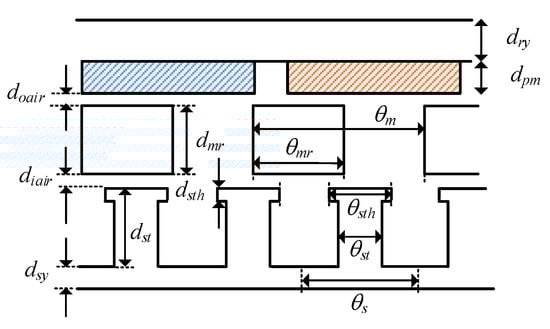
Figure 7.
Two-dimensional cross-section at average diameter corresponding parameters.
Table 3.
Optimized parameters and optimization range.
The optimization procedure of the proposed machine is shown in Figure 8. The genetic algorithm (GA) is employed as the optimization algorithm. The process is given as follows. First, the optimization targets are set as the output torque and ripples while the population quantity is selected as 100 considering the computing power. Secondly, the models with different parameters are generated, selected, and calculated. Then, the parameter combinations with better performance are saved and used for the optimization of the next generation, otherwise, those solutions will be removed and new models will be supplemented. Thirdly, if the iterations reach the setpoint, the optimization progress is finished and the optimized solutions are saved. After optimization, the relationship among torque, ripple, and torque versus PM consumption is given in Figure 9.
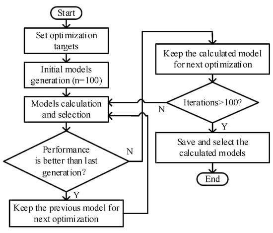
Figure 8.
Optimization progress of the proposed machine.
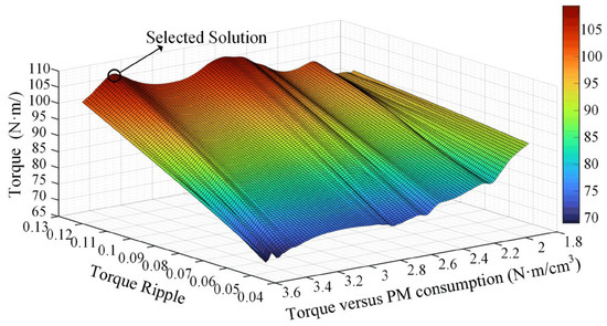
Figure 9.
Relationship among torque, ripple, and torque versus PM of the proposed machine.
The optimized parameters and optimization range are given in Table 3, which can achieve a torque of 107.2 N·m with a ripple of 0.12. To conduct a fair comparison, the contrast models, including the generalized coaxial-flux MGM [27,28], axial-flux MGM [29], and surface-mounted PM machine, are optimized which have the same fixed parameters given in Table 1. The optimization results are given in Figure 10. As shown in Figure 10, the output torque of the generalized coaxial-flux, axial-flux MGM machine, and PM machine is 83.9, 82.1, and 69.8 N·m, respectively.
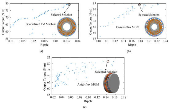
Figure 10.
Optimization results of the contrast models. (a) The PM machine. (b) Coaxial flux MGM. (c) Axial flux MGM.
4. Performance Analysis and Comparison
4.1. Magnetic Field Analysis
The magnetic field data analysis and performance evaluation was conducted via Ansys/Maxwell. Figure 11 indicates the magnetic field distribution and magnetic flux density of the proposed structure calculated by finite element analysis (FEA) under the no-load and full-load conditions. As shown in Figure 10, the iron indicates no saturation under the rated condition.
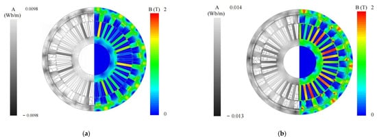
Figure 11.
Magnetic flux lines distribution and flux density distribution of proposed structure under no-load and full-load condition. (a) No-load condition. (b) Full-load condition.
The calculated air-gap harmonics distribution of the proposed machine with △θ of 0, −5, and −10 deg are presented in Figure 12. As shown in Figure 12, the air gap harmonics distribution is stable with different values of , indicating the deviation given in Equation (9)—the flux in air gap will not be affected by .
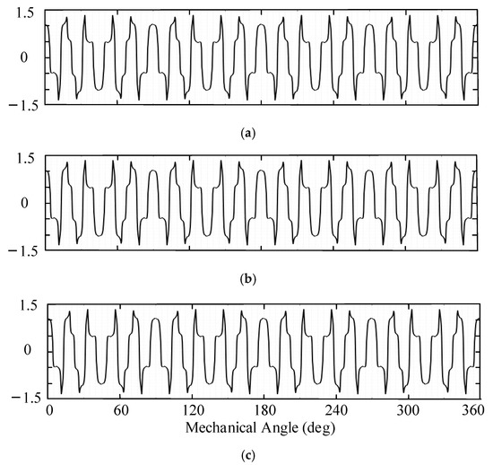
Figure 12.
Air gap flux distribution with different . (a) = 0 deg. (b) = −5 deg (selected ). (c) = −10 deg.
The harmonics spectrum conducted by FFT (Fast Fourier Transform) is given in Figure 13, indicating the operating harmonics of the proposed machine. As shown in Figure 13, the 4th and 20th are the operating frequency of the proposed machine.
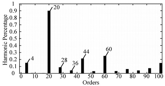
Figure 13.
Harmonics of air gap flux.
4.2. Stator Position Modulation
Based on Equation (14), the phase difference between auxiliary winding and armature winding of the proposed machine can be found via the stator rotation angle . As for the proposed combination, the phase difference is zero when the equals −5 deg. The induced voltages of the auxiliary winding and armature winding with the of −5 deg are given in Figure 14.
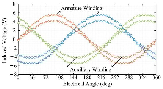
Figure 14.
Induced voltages of the proposed machine with of −5 deg.
As shown in Figure 14, the induced voltage of the auxiliary winding is in phase with that of the armature winding when equals −5 deg. Moreover, the induced voltage of those two sets of windings with the of 0 and −10 deg are given in Figure 15 as supplementary.
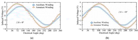
Figure 15.
Induced voltages of the proposed machine with different . (a) 0 deg. (b) −10 deg.
To verify the proposed design approach, the versus the phase difference and induced voltage amplitude are given in Figure 16a,b, respectively. As shown in Figure 16a, the finite element analysis (FEA) results correspond with the deviation given in Equation (14). Moreover, as shown in Figure 16b, the amplitude of induced voltages is slightly affected by the , verifying the deviation given in Equations (10) and (14).
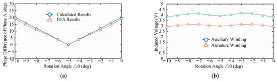
Figure 16.
Phase difference and induced voltage versus rotation angle. (a) Phase difference versus rotation angle . (b) Effective value of induced voltages versus rotation angle .
With the of −5 deg, the topology of the driving system can be simplified into a single three-phase inverter, which is given in Figure 17. Otherwise, the driving system requires two sets of a three-phase inverter.
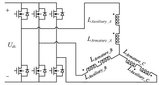
Figure 17.
Driving system of the proposed machine.
4.3. Torque Performance Comparison
To conduct a detailed comparison, the proposed machine will be compared to the optimized surface-mounted PM machine (pole pair is 20/4 and slot number is 36) and generalized magnetic-geared machine, including the rated torque, overload capability, and cogging torque. The torque performance of the proposed machine, the PM machine, and generalized coaxial-flux and axial-flux MGM is given in Figure 18.
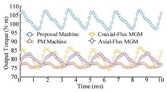
Figure 18.
Torque of proposed machine and contrast models.
As shown in Figure 18, the output torque of the proposed machine reaches 106.2 N·m while that of the generalized PM machine, coaxial-flux, and axial flux MGM only reaches 77.9, 83.1, and 82.1 N·m with the same copper loss, respectively. Under that condition, the current density of the proposed machine, PM machine, and magnetic geared machine is 6, 6.76, 6.38, and 6.53 A/mm2, respectively. In addition, the torque ripple of the proposed machine is higher than that of the PM machine but lower than that of the magnetic geared machine, reaching 12.9% compared to the output torque.
The cogging torque of the proposed machine and contrast models are given in Figure 18. As shown in Figure 19, the cogging torque of the proposed machine is larger than that of the PM machine but lower than that of the magnetic geared machine, which takes up 0.13 compared to the rated output torque.
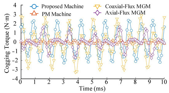
Figure 19.
Cogging torque of proposed machine and contrast models.
To better illustrate the effectiveness of the dual-series winding design, Figure 20 indicates the torque versus electrical angle of the proposed machine with the sole armature winding excitation, auxiliary winding excitation, and dual winding excitation with the △θ of −5 deg. As shown in Figure 20, the torques generated by armature winding and auxiliary winding are totally in-phase under different electrical angles.
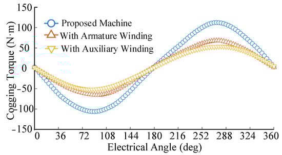
Figure 20.
Angle–torque characteristics of the proposed machine and contrast models.
The overload capability of the proposed machine and the corresponding comparison machines are shown in Figure 21. As shown in Figure 21a, Under the rated current density of 6 A/mm2, the torque of the proposed machine, PM machine, coaxial flux, and axial flux MGM are 106.6, 69.8, 83.5, and 82.1 N·m, respectively. As for the torque improvement of the proposed machine compared to contrast models, the corresponding results are given in Figure 20b. As shown in Figure 20b, the improvement compared to MGMs are stable under different current density, reaching 30%. However, compared to the PM machine, the torque improvement will decrease with the increase of the current density.
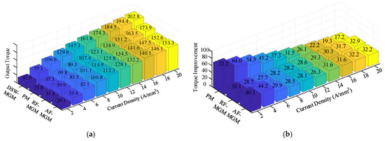
Figure 21.
Overload capability and torque improvement of proposed machine and contrast models. (a) Torque of the proposed machine and contrast models versus current density. (b) Torque improvement between the proposed machine and contrast models.
4.4. Efficiency and Loss Comparison
A comprehensive comparison between the proposed machine, surface-mounted PM machine, coaxial flux, and axial flux MGM is shown in Table 4, including the loss, efficiency, torques, and detailed parameters. As shown in Table 4, the proposed machine can improve the torque, torque density, and torque per PM consumption compared to the PM machine and coaxial flux and axial flux MGM, from 77.5, 83.9, 82.1 N·m, 9.72, 8.88, 8.43 N·m/kg, 127.68, 94.41, 114.02 N·m/kg to 107.2 N·m, 10.81 N·m/kg, and 150.7 N·m/kg, respectively.
Table 4.
Comprehensive performance comparison.
Moreover, the proposed machine has a higher efficiency of 93.2% than that of the PM machine of 90.1%, coaxial MGM of 90.6%, and axial flux MGM of 90.0%. Even if the weight of the proposed machine is the largest, the overall performance of the proposed machine still indicates an obvious superiority. Furthermore, to better investigate the efficiency performance of the proposed machine, the efficiency versus current density is given in Figure 22. As shown in Figure 21, the efficiency of the proposed machine and contrast models will decrease with the increase of the current density. Under the current density of 20 A/mm2, the proposed machine still has the highest efficiency among those three machines, reaching 66.8%.
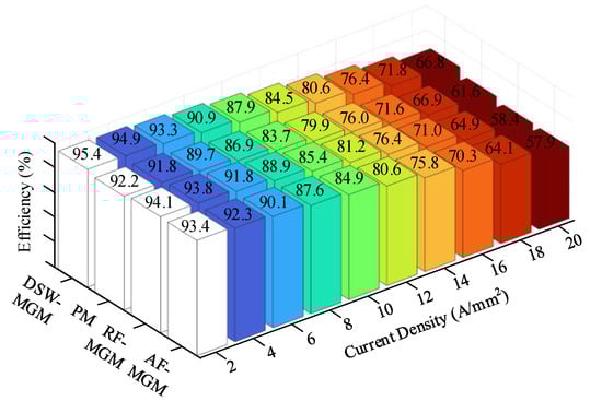
Figure 22.
Efficiency versus the current density of the proposed machine and PM machine.
Based on the abovementioned analysis, in the future, the proposed machine has a strong potential for electric vehicles powertrain with improved performance, which will promote the establishment of an environmentally friendly society [30,31].
5. Conclusions
In this paper, a dual-series-winding magnetic geared machine (MGM) and its design approach are proposed and verified. The proposed design improves torque performance and space utilization of the MGM with the introduction of the auxiliary winding. The stator of the machine is rotated by 5 deg to ensure the excitation of the auxiliary winding is in phase with that of the armature winding, accordingly, can be driven by a single three-phase inverter. Compared to the coaxial flux, axial flux MGM, and surface PM-mounted machine (SPM), the output torque can be improved from 83.9, 82.1, and 77.5 to 107.2 N·m with the same copper loss. Moreover, the torque density versus machine weight and PM consumption compared to the coaxial flux, axial flux MGM, and PM machine are enhanced from 8.88/8.43/9.72 N·m/kg, and 94.41/114.02/127.68 N·m/kg to 10.81 N·m/kg, and 150.17 N·m/kg, respectively. In addition, the proposed machine indicates a good overload capability. When the current density overloads more than 3 times compared to the nominated condition, the proposed machine still indicates a 19% torque improvement compared to the PM machine and near 30% compared to MGMs. Furthermore, the proposed machine has the highest among contrast models, reaching 93.2% under the nominated conditions while that of the coaxial flux, axial flux MGM, and PM machine only reaches 90.6%, 90.0%, and 90.1%, respectively. Based on the abovementioned results, the proposed machine has superiority in electric vehicle powertrain, indicating a strong scale-up feasibility in the future.
Author Contributions
Conceptualization, Y.C.; methodology, S.W.; software, Y.C.; validation, W.F. and S.N.; formal analysis, S.W.; investigation, Y.C.; writing—original draft preparation, Y.C.; writing—review and editing, S.N.; supervision, S.N. and W.F.; project administration, S.N.; funding acquisition, S.N. All authors have read and agreed to the published version of the manuscript.
Funding
His research was funded by Research Grant Council of the Hong Kong SAR Government grant number PolyU152180/19E.
Institutional Review Board Statement
Not applicable.
Informed Consent Statement
Not applicable.
Data Availability Statement
Not applicable.
Conflicts of Interest
The authors declare no conflict of interest.
References
- Liu, C.; Chau, K.T.; Lee, C.H.T.; Song, Z. A Critical Review of Advanced Electric Machines and Control Strategies for Electric Vehicles. Proc. IEEE 2021, 109, 1004–1028. [Google Scholar] [CrossRef]
- Barkenbus, J.N. Prospects for Electric Vehicles. Sustainability 2020, 12, 5813. [Google Scholar] [CrossRef]
- Muzir, N.A.Q.; Mojumder, M.R.H.; Hasanuzzaman, M.; Selvaraj, J. Challenges of Electric Vehicles and Their Prospects in Malaysia: A Comprehensive Review. Sustainability 2022, 14, 8320. [Google Scholar] [CrossRef]
- Agamloh, E.; von Jouanne, A.; Yokochi, A. An Overview of Electric Machine Trends in Modern Electric Vehicles. Machines 2020, 8, 20. [Google Scholar] [CrossRef]
- Chen, Y.; Zhao, X.; Ho, S.; Niu, S.; Fu, W. Design and optimization of yokeless magnetic gear with asymmetric Halbach permanent magnet array for electric vehicle powertrain. IET Renew. Power Gener. 2022, 16, 2223–2232. [Google Scholar] [CrossRef]
- Ruan, Z.; Song, W.; Zhang, Y.; Yao, G.; Guo, Y. A Variable Switching Frequency Space Vector Pulse Width Modulation Technique Using Virtual Flux Ripple. IEEE Trans. Emerg. Sel. Topics Power Electron. 2022. [Google Scholar] [CrossRef]
- Cheng, M.; Sun, L.; Buja, G.; Song, L. Advanced Electrical Machines and Machine-Based Systems for Electric and Hybrid Vehicles. Energies 2015, 8, 9541–9564. [Google Scholar] [CrossRef]
- Irimia, C.; Grovu, M.; Husar, C.; Fodorean, D.; Antonya, C. Co-Simulation Analysis for an Electric Vehicle Powered by a High-Speed Electrical Machine. In Proceedings of the 2017 IEEE Vehicle Power and Propulsion Conference (VPPC), Belfort, France, 11–14 December 2017; pp. 1–6. [Google Scholar]
- Guo, X.; Liu, G.-P.; Shirazee, N.; Williams, J. Electronic–magnetic gearing motor analyses and simulations for electric vehicles. IET Electr. Syst. Transp. 2018, 8, 95–100. [Google Scholar] [CrossRef]
- Xie, S.; Chen, H.; Zuo, Y.; Shen, F.; Han, B.S.; Hoang, C.C.; Lee, C.H.T. A Consequent-Pole Magnetic-Geared Machine with Axially Embedded Permanent Magnets for Hybrid Electric Vehicle. IEEE Access 2021, 9, 14905–14917. [Google Scholar] [CrossRef]
- Chau, K.T.; Zhang, D.; Jiang, J.Z.; Liu, C.; Zhang, Y. Design of a Magnetic-Geared Outer-Rotor Permanent-Magnet Brushless Motor for Electric Vehicles. IEEE Trans. Magn. 2007, 43, 2504–2506. [Google Scholar] [CrossRef]
- Zhao, H.; Liu, C.; Song, Z.; Yu, J. Analytical Modeling and Comparison of Two Consequent-Pole Magnetic-Geared Machines for Hybrid Electric Vehicles. Energies 2019, 12, 10. [Google Scholar] [CrossRef]
- Liu, C.; Yu, J.; Lee, C.H.T. A New Electric Magnetic-Geared Machine for Electric Unmanned Aerial Vehicles. IEEE Trans. Magn. 2017, 53, 1–6. [Google Scholar] [CrossRef]
- Jian, L.; Gong, W.; Xu, G.; Liang, J.; Zhao, W. Integrated Magnetic-Geared Machine with Sandwiched Armature Stator for Low-Speed Large-Torque Applications. IEEE Trans. Magn. 2012, 48, 4184–4187. [Google Scholar] [CrossRef]
- Zhang, X.; Liu, X.; Chen, Z. A Novel Coaxial Magnetic Gear and Its Integration with Permanent-Magnet Brushless Motor. IEEE Trans. Magn. 2016, 52, 1–4. [Google Scholar] [CrossRef]
- Yousefnejad, S.; Heydari, H.; Akatsu, K.; Ro, J.-S. Analysis and Design of Novel Structured High Torque Density Magnetic-Geared Permanent Magnet Machine. IEEE Access 2021, 9, 64574–64586. [Google Scholar] [CrossRef]
- Wang, Q.; Niu, S.; Yang, S. Design Optimization and Comparative Study of Novel Magnetic-Geared Permanent Magnet Machines. IEEE Trans. Magn. 2017, 53, 1–4. [Google Scholar] [CrossRef]
- Liu, C.; Chau, K.T.; Zhang, Z. Novel Design of Double-Stator Single-Rotor Magnetic-Geared Machines. IEEE Trans Magn. 2012, 48, 4180–4183. [Google Scholar] [CrossRef]
- Zhu, Z.Q.; Khatab, M.F.; Li, H.; Liu, Y. A Novel Axial Flux Magnetically Geared Machine for Power Split Application. IEEE Trans Ind. Appl. 2018, 54, 5954–5966. [Google Scholar] [CrossRef]
- Johnson, M.; Gardner, M.C.; Toliyat, H.A. Design and Analysis of an Axial Flux Magnetically Geared Generator. IEEE Trans Ind. Appl. 2017, 53, 97–105. [Google Scholar] [CrossRef]
- Suzuki, H.; Hirata, K.; Niguchi, N.; Kohara, A.; Takahara, K. Maximum Torque Control of Magnetic-Geared Motors. In Proceedings of the 19th International Symposium on Electromagnetic Fields in Mechatronics, Electrical and Electronic Engineering (ISEF), Nancy, France, 29–31 August 2019; pp. 1–2. [Google Scholar]
- Verbanac, N.; Bulić, N.; Jungmayr, G.; Marth, E. Nonlinear Position Control of a Magnetic-Geared Servo Drive With Unknown Load. In Proceedings of the 2022 International Conference on Smart and system Technologies (SST), Osijek, Croatia, 19–21 October 2022; pp. 263–268. [Google Scholar]
- Wang, Y.; Ho, S.L.; Fu, W.N.; Shen, J.X. A Novel Rotor Position Detection Method for Sensorless Control of Magnetic-Geared Permanent-Magnet Brushless Motor. IEEE Trans. Magn. 2013, 49, 3961–3964. [Google Scholar] [CrossRef]
- Wang, K.; Xue, Y.; Guo, Q.; Shahidehpour, M.; Zhou, Q.; Wang, B.; Sun, H. A Coordinated Reconfiguration Strategy for Multi-Stage Resilience Enhancement in Integrated Power Distribution and Heating Networks. IEEE Trans. Smart Grid 2023. [Google Scholar] [CrossRef]
- Ho, S.L.; Niu, S.; Fu, W.N. Design and Analysis of a Novel Axial-Flux Electric Machine. IEEE Trans. Magn. 2011, 47, 4368–4371. [Google Scholar] [CrossRef]
- Chen, Y.; Fu, W.; Weng, X. A Concept of General Flux-Modulated Electric Machines Based on a Unified Theory and Its Application to Developing a Novel Doubly-Fed Dual-Stator Motor. IEEE Trans. Ind. Electron. 2017, 64, 9914–9923. [Google Scholar] [CrossRef]
- Shin, H.; Chang, J. Comparison of Radial Force at Modulating Pieces in Coaxial Magnetic Gear and Magnetic Geared Machine. IEEE Trans. Magn. 2018, 54, 1–4. [Google Scholar] [CrossRef]
- Zhu, Z.Q.; Liu, Y. Analysis of Air-Gap Field Modulation and Magnetic Gearing Effect in Fractional-Slot Concentrated-Winding Permanent-Magnet Synchronous Machines. IEEE Trans. Ind. Electron 2018, 65, 3688–3698. [Google Scholar] [CrossRef]
- Khatab, M.F.H.; Zhu, Z.Q.; Li, H.Y.; Liu, Y. Comparative study of novel axial flux magnetically geared and conventional axial flux permanent magnet machines. CES Trans. Elect. Mach. Syst. 2018, 2, 392–398. [Google Scholar] [CrossRef]
- Kumar, R.; Pachauri, R.K.; Badoni, P.; Bharadwaj, D.; Mittal, U.; Bisht, A. Investigation on parallel hybrid electric bicycle along with issuer management system for mountainous region. J. Clean. Prod. 2022, 362, 132430. [Google Scholar] [CrossRef]
- Kumar, R.; Kumar, A.; Gupta, M.K.; Yadav, J.; Jain, A. Solar tree-based water pumping for assured irrigation in sustainable Indian agriculture environment. Sustain. Prod. Consum. 2022, 33, 15–27. [Google Scholar] [CrossRef]


Disclaimer/Publisher’s Note: The statements, opinions and data contained in all publications are solely those of the individual author(s) and contributor(s) and not of MDPI and/or the editor(s). MDPI and/or the editor(s) disclaim responsibility for any injury to people or property resulting from any ideas, methods, instructions or products referred to in the content. |
© 2023 by the authors. Licensee MDPI, Basel, Switzerland. This article is an open access article distributed under the terms and conditions of the Creative Commons Attribution (CC BY) license (https://creativecommons.org/licenses/by/4.0/).