Article

Study on Deformation Characteristics of Surrounding Rock of Roadway with Coal–Rock Interface

1
State Key Laboratory of Mining Response and Disaster Prevention and Control in Deep Coal Mines, Anhui University of Science and Technology, Huainan 232001, China
2
School of Mining Engineering, Anhui University of Science and Technology, Huainan 232001, China
*
Authors to whom correspondence should be addressed.
Sustainability 2023, 15(6), 5347; https://doi.org/10.3390/su15065347
Submission received: 11 December 2022 / Revised: 14 March 2023 / Accepted: 14 March 2023 / Published: 17 March 2023
(This article belongs to the Special Issue Green and Scientific Design of Deep Underground Engineering)

Abstract

:
Surrounding rock of roadway with a coal–rock interface is a common form in coal mines. In order to determine deformation characteristics and obtain the control principle of roadways with a coal–rock interface, the interface between the roof and coal seam was added to simulate the weak cohesion between the stratum. In this model, the interface shear stiffness was considered to be one of the key factors affecting horizontal inward movement of the roadway sidewalls. The deformation of the roadway with or without coal–rock interface under different burial depths was analyzed. Then, the shear stiffness of the interface element was changed to study the influence of shear stiffness on roadway deformation. At the same time, the characteristics of discontinuous deformation caused by the coal–rock interface at different positions in the roadway were studied. The results show that the roadway sidewall appeared to bulge in the middle and there is no dislocation and a small deformation in the contact position of the roadway sidewall with the roof and the floor when there is no interface between the stratum of the roadway. When there is an interface, the sidewall of the roadway is extruded as a whole, the slip and dislocation between the coal sidewall and the roof were obvious, and the maximum deformation of the sidewall is 1.68 times that of the roadway without an interface. When the shear stiffness of the interface is low, the deformation and the range of the plastic zone of roadway are large, with a large deformation at the upper part of the roadway sidewall, and a small deformation at the lower part of the roadway sidewall. The deformation of sidewall at the interface position decreases gradually with the increase of the interface shear stiffness, approaching the shape without the interface. When the coal–rock interface is at the sidewall of the roadway, the deformation of the rock and coal body at the interface is discontinuous, with slip and dislocation. The greater the proportion of rock height in the roadway sidewall, the greater the rock deformation. On the contrary, the coal deformation increases. It is more reasonable to simulate the deformation of roadways by adding a coal–rock interface, and the results are closer to the actual situation.

1. Introduction

The surrounding rock sidewall structure of roadways with a coal–rock interface is generally composed of rock and coal. The boundary between coal and rock strata is exposed in the roadway free face, which is one of the commonly occurring forms of roadway surrounding rock in coal mines. Compared with the roadway arranged in the complete rock stratum, the sidewall of roadway with a coal–rock interface has the characteristics of large and discontinuous deformation, which brings some difficulties to the roadway support.
For the study of coal–rock interface, scholars [1,2,3,4,5,6] have conducted mechanical strength tests on combinations of different coal–rock proportions and combinations, and analyzed the mechanical parameters of the combination specimens. Zhao carried out mechanical and energy analysis on the whole process of deformation and failure of like coal–rock materials with different combinations under uniaxial load, and the evolution law of elastic properties and dissipated energy in the full stress–strain process of the specimen was revealed [7]. The influence of interface dip angle and fractal dimension on the combination was revealed by an investigation of 25 combinations with different interface fractal dimensions and dip angles [8]. The mechanical structure model of coal and rock have been established, the influence of different interface connection modes on coal and rock have been analyzed, and the mechanical properties (plastic zone, stress and displacement) and energy of coal–rock composite structure under different interface connection modes have been studied through numerical simulation [9]. The slip-failure mechanism of coal–rock structure under horizontal-unloading-biaxial compression has been studied [10]. The influence of interface cohesive strength, rock strength and stress level on the failure behavior of the composite model has been established [11]. The above studies explain the influence of the interface on the mechanical properties of coal and rock from the perspective of the constraint effect of the coal–rock interface and the dip angle of the coal–rock interface, but lack research on the shear resistance of the coal and rock interface.
For the study of coal-bearing interface roadway in coal and rock mass, the influence of the mechanical parameters of coal–rock interface on the stability of sidewalls has been analyzed, and the deformation mechanisms of this type of roadway, including the mechanism of interlaminar shear failure of coal–rock interface and the mechanism of inducing interlaminar instability of interface, have been established [12]. The stress, deformation and failure laws of the roadway under the main control factors such as different dip angles of coal–rock interface have been studied, and the deformation-failure-instability mechanisms of the surrounding rock of deep half-coal rock roadway have been revealed [13,14]. The asymmetric-distribution characteristics of the failure in the surrounding rock of the steeply inclined coal–rock interbedding roadway has been analyzed, and the large deformation of the sidewalls caused by the staggered deformation of the structural planes between the lower layers under the horizontal stress has been established [15,16]. Through a series of uniaxial compression tests on inclined coal–rock combination specimens (with an inclination angle of coal and rock contact surfaces of 15°, 30° and 45°) with and without anchors in the horizontal direction, the failure mechanism of coal–rock anchor combination solid formed by support structure and coal rock mass has been thoroughly studied [17]. Through the direct shear test on the natural coal–rock interface specimen, the stress effect and lithologic effect of the coal rock combination specimen affected by the interface have been revealed [18]. The influence of rock in coal–rock samples on coal mechanical behavior has been established, and it has been determined that the greater the proportion of coal body, the lower the strength of the combination [19,20]. For roadways with coal–rock interface, most of the research focuses on the research and control of roadway deformation with an inclined interlayer structural plane, while there is less research on the constraint effect of horizontal coal-bearing rock interface on roadway instability.
This model tests the effect of interface shear stiffness on the anti-sliding ability of the sidewall during the deformation and instability of the coal-bearing rock interface roadway, which is innovative. Firstly, the deformations of the roadway with and without coal–rock interface are compared, and it is pointed out that the coal–rock interface deformation is more in line with the actual situation. Then, the deformation of single-interface roadway and multi-interface roadway are analyzed, respectively, which is consistent with the deformation of roadways in different coal and rock strata thickness and interlayer states. The deformation state of the coal–rock interface at different positions of the roadway sidewall are observed, which provides reference for the deformation of the semi-coal–rock roadway, and the determination of weak points in roadway with coal–rock interface has practical value for formulating targeted support methods.

2. Roadway Model and Analysis

The coal stratum of the roadway with coal–rock interface has low strength and a large deformation compared with the rock stratum. The coal is deformed and destroyed first under the high vertical stress, and will produce shear slip along the fracture surface. The inclined observation borehole was drilled on the side wall, and the borehole penetrated into the coal seam roof from the side wall as shown in Figure 1. The observation showed that the side wall and roof of the roadway also had a certain degree of separation in the coal pillar. For roadways with weak cohesiveness between coal and rock layers, due to the inconsistent deformation of coal and rock, there is a lack of restraint between the rock layers and coal seams. The sidewall of the coal body in the roadway is easily squeezed and deformed along the coal–rock interface, if targeted support measures are not taken, the support strength is low or the support mode is unreasonable, resulting in a series of discontinuous, large-scale instability, destruction and deformation, such as large deformation shrinkage, roof subsidence and the floor of the roadway. The sidewall deformation of roadway coal is large, which cannot effectively support the roof, and making it difficult to form a “small structure” that balances the sidewall, roof and floor. If the deformation continues to occur, safety accidents will be caused and mine safety production will be affected. A typical deformation of a coal–rock interface is shown in Figure 1. The roadway was excavated along the sandstone roof of the coal stratum. The roadway roof steel belt was squeezed by the coal sidewall, and the coal sidewall was completely squeezed into the roadway.
In this paper, the interface structure unit in FLAC3D was used to simulate the coal–rock interface. The interface element consists of a series of three node triangular elements, and allocating the triangle area to each node, each node has a related representation area. When another mesh face is connected to the interface element, the interface node will be generated. The interface element can be connected with the solid element surface (target surface) through nodes. The force on the normal direction of the contact surface is determined by the orientation of the target surface. Figure 2 shows the constitutive model of the interface. According to Coulomb shear strength criterion, the maximum shear force Fsmax required for relative sliding of the contact surface was calculated by Formulas (1) and (2):
F s i ( t + Δ t ) = F s i ( t ) + k s Δ u s i ( t + 0.5 Δ t ) A + A σ s i
F s max = c i f A + tan φ i f ( F n u A )
where, F s i ( t + Δ t ) is the shear force vector at t + Δ t , Δ u s i is the relative shear displacement increment vector, σ s i is the additional shear stress caused by contact surface stress initialization, ks is the shear stiffness of the contact surface element, A is the representative area of the contact surface node, c i f is the cohesion of the contact surface, φ i f is the friction angle of the contact surface and u is pore pressure.
When the shear stiffness on the contact surface is less than the maximum shear force ( | F s | < F s max ), the contact surface is in the elastic stage. When the shear force on the contact surface is equal to the maximum shear force ( | F s | = F s max ), the contact surface enters the plastic stage. The change of shear force is linear with shear stiffness. The interface is used to simulate the influence of joints, faults and friction interfaces between the bodies, and allows sliding and separation between the two interfaces to change the ks of the contact surface (the shear stiffness of the contact surface) which will affect the shear displacement between the two rock layers. Therefore, the interface connection can be used to more accurately represent the slip and dislocation between layers for the contact between rock layers in the field.
When studying the deformation law of the roadway with coal–rock interface, due to the lack of consideration of the role of the coal seam and roof rock interface, the deformation state and stress deformation characteristics of the surrounding rock of the roadway cannot be accurately described. The Mohr Coulomb constitutive model was selected in this paper, and the tunnel model established is shown in Figure 3.
The length × the width × the height of the model is 83 m × 15 m × 55 m, and the model was divided into 27,000 units and 33,124 nodes. The width × the height of the roadway is 3 m × 3 m, which was excavated 5 times, for 3 m each time. Six groups of loads with different burial depths were applied, which are 300 m, 350 m, 400 m, 450 m, 500 m and 550 m, respectively. The boundary conditions of the tunnel model are set as follows: the fixed constraints are imposed on the bottom boundary of the model, the horizontal displacement constraints are imposed in the mode, and the equivalent load of overburden is applied on the top of the model. The coal–rock interface between the wall and the roof is added. The shear stiffness of the weakened coal–rock interface is 0.05 GPa·m−1. The normal stiffness is 10 times the strength of the surrounding rock stratum according to the literature [21]. The value is 30 GPa·m−1 and the friction angle is 15°. It should be noted that to reduce variables, the coal seam is in the roadway floor, and there is no coal–rock interface between the sidewalls and the floor, which is one of the widespread problems. The overburden load is calculated by Formula (3):
σ z = γ H
where, γ is the average unit weight of the model, the value is 25 kN/m and H is the overburden thickness of the model.
Table 1 shows the selection of the physical and mechanical parameters of the model roof-rock, the coal body and its residual rock seam:

2.1. Stress and Deformation of Roadway

For the roadways with weak cohesiveness between coal and rock strata, under the action of high stress, there is a lateral slip and dislocation between the roof and the coal pillar, and the cohesiveness between the coal and rock strata has a significant impact on the deformation of the surrounding rock of the roadway. The coal pillar has no lateral constraint of the roof, and the surrounding rock may have a large range of slip deformation along the coal–rock interface.
Figure 4 shows the cloud diagram of roadway vertical stress distribution when there is no coal–rock interface. It can be seen from the figure that the maximum vertical stress of the roadway is mainly distributed within 1.2 m~2.7 m from both sides of the coal pillar, and with the increase of burial depth, the high-stress-concentration area gradually increases, and transfers to the interior of the coal pillar. The surrounding rocks on both sides of the roadway and the shallow part of the roof and floor are stress-reduction areas, and the actual stress is lower than the loading stress value. When the buried depth is 550 m, the maximum stress-concentration area is approximately 2.7 m away from the roadway wall.
Formula (4) defines the stress concentration factor K as the ratio of roadway stress σ after the roadway opening and original rock stress σp, reflecting the degree of stress concentration in the roadway area.
K = σ σ p
The horizontal stress-concentration factor of the roadway without coal–rock interface is between 1.48 and 1.98, and the vertical stress-concentration factor is between 1.26 and 1.49.
The stress distribution of surrounding rock of roadway with interface is significantly different from that without interface, as shown in Figure 5. When there is coal–rock interface, the vertical stress-concentration area of the roadway side is closer to the bottom corner of the roadway, and with the increase of surrounding rock stress, the damage area of the floor and side gradually increases, the range of stress-reduction area increases, and the vertical stress-concentration area of the side gradually transfers to the roadway roof and away from the roadway location. The peak stress of coal–rock interface roadway increases gradually with the increase of burial depth. The horizontal stress-concentration factor is between 1.52 and 1.82, and the vertical stress-concentration factor is between 1.24 and 1.61. The horizontal stress-concentration coefficient of roadway with interface is slightly larger than that of the roadway without interface, and the difference of the vertical stress-concentration coefficient is small.
Displacement monitoring points are arranged around the roadway, as shown in Figure 6. 9 monitoring points are arranged on both sides of the roadway, 16 monitoring points are arranged on the roof and floor and the monitoring points are the nodes around the roadway.
Figure 7a shows the displacement and deformation of the left sidewall of the roadway without coal–rock interface under the burial depths of 300 m, 350 m, 400 m, 450 m, 500 m and 550 m, and Figure 7b shows the displacement and deformation of the left sidewall of the roadway with coal–rock interface. It can be seen that:
(1)
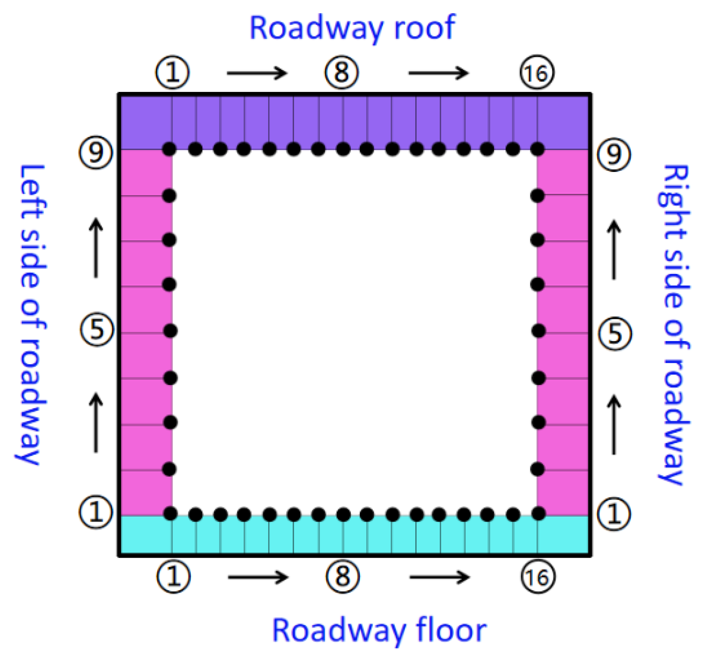
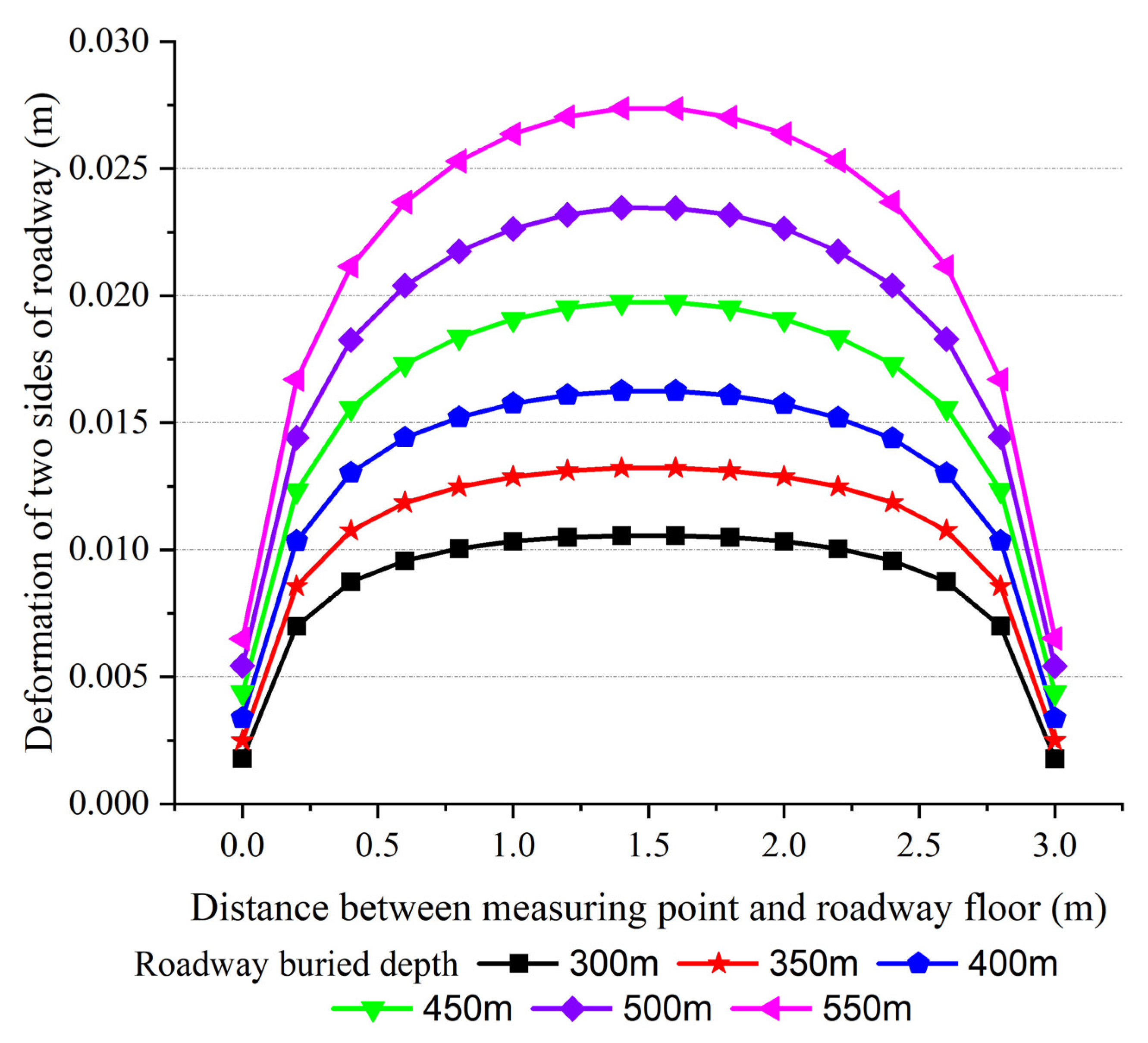
The displacement and deformation of the sidewalls without coal–rock interface are large in the middle and small at both ends. The lateral deformation of the contact position between the roadway side and the top and bottom is very small, and the lateral displacement of the contact position between the top and bottom is smaller than that of the contact position between the top and bottom. The free faces of both sides of the roadway protrude in the roadway, due to the lack of connection constraints between roof and wall in the roadway with coal–rock interface. The lateral displacement of the upper part of the roadway wall in contact with the roof is the largest; it decreases slightly downward, and the contact with the floor is the smallest.
(2)
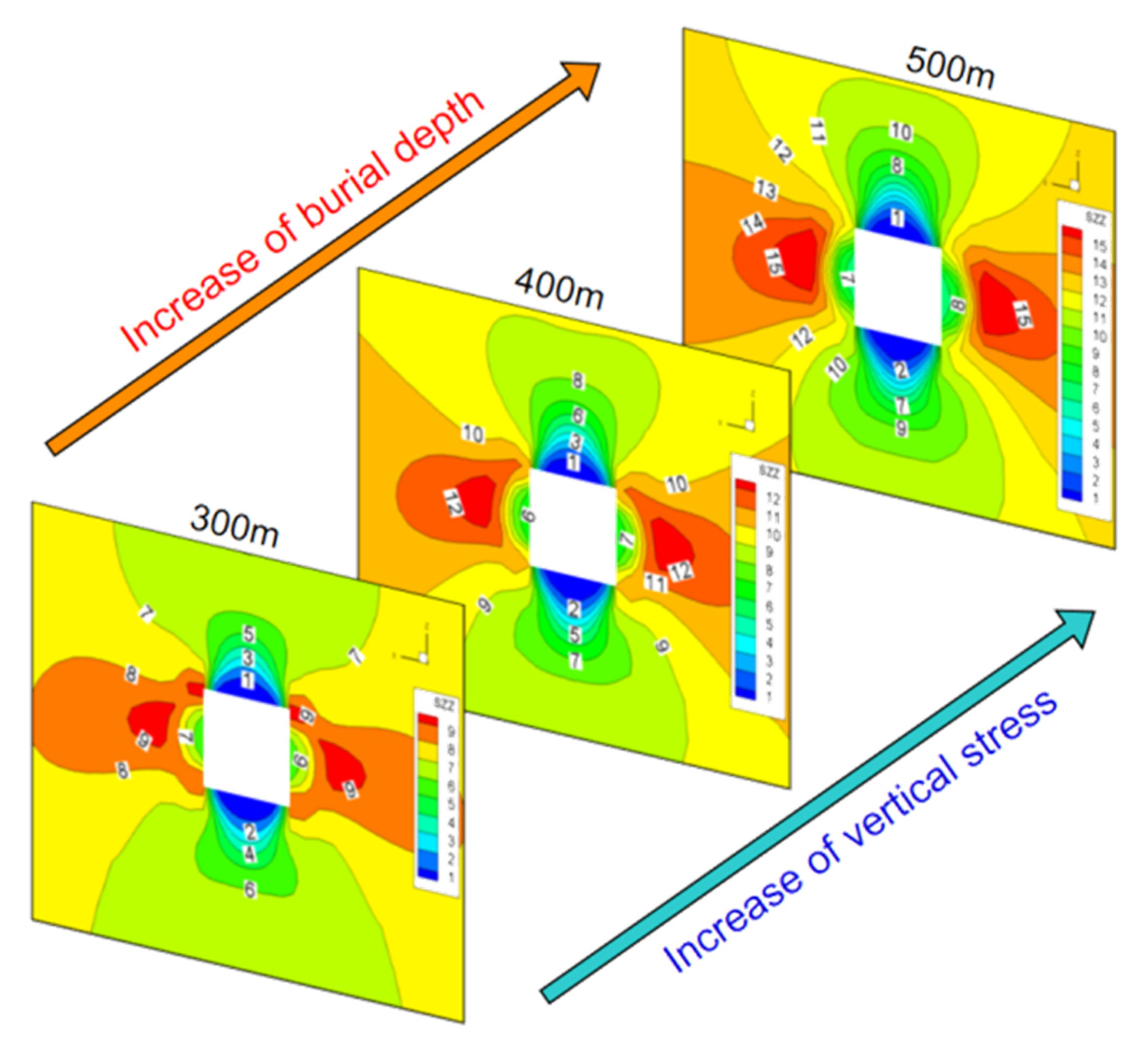
The displacement of both sides of the roadway is positively correlated with the increase of burial depth. The greater the burial depth is, the greater the deformation of the roadway is. With the increase of burial depth, the displacement of the middle part of the side of the roadway with coal–rock interface gradually increases. Except for the small displacement of the measuring points at the contact with the floor, the displacement of the other measuring points has little difference. In addition, the floor heave occurs during the loading process of the roadway, and the roadway presents the deformation characteristics of the whole side extruding toward the interior of the roadway.
(3)
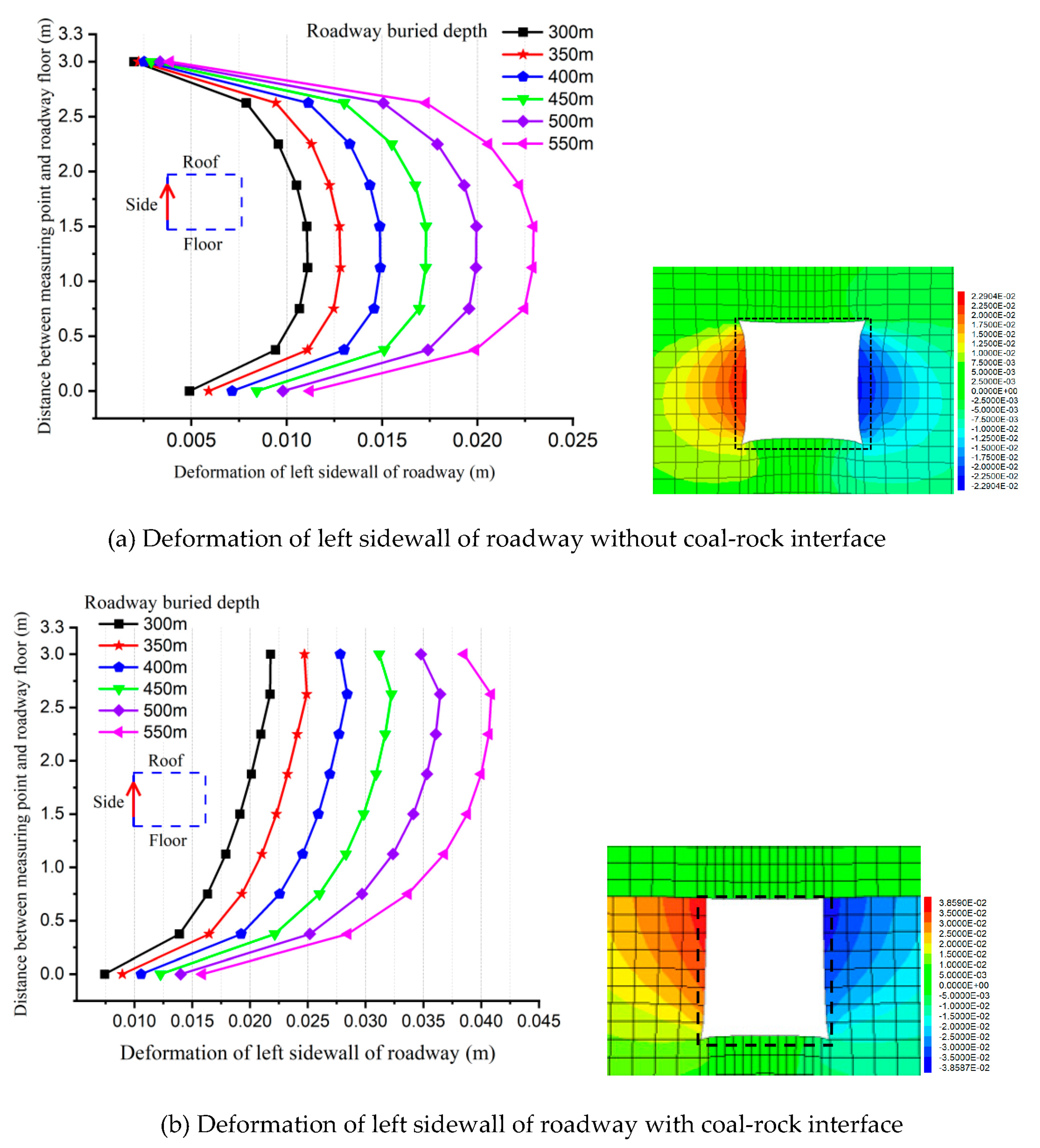
When the buried depth of the roadway is 300 m, the maximum deformation of the wall of the roadway without coal–rock interface is 1.11 cm and the maximum deformation of the wall of the roadway with coal–rock interface is 2.2 cm. When the buried depth is 550 m, the maximum deformation is 2.29 cm and 3.85 cm, respectively, with a difference of 1.56 cm, which is 1.68 times the deformation of the roadway without the interface model.
The displacement and deformation of the roof and the floor can be seen as follows, as shown in Figure 8 and Figure 9:
(1)
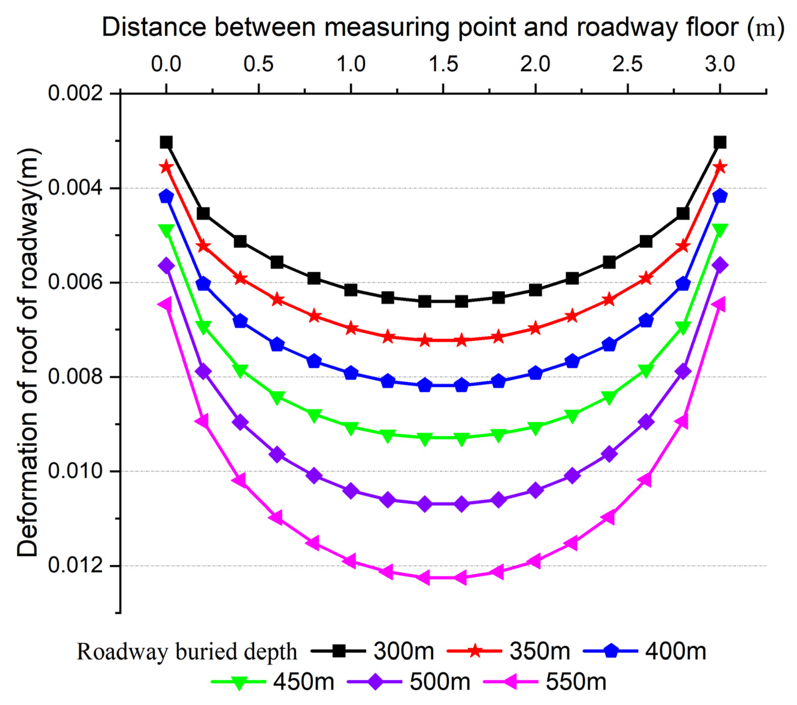
With or without coal–rock interface, the deformation form of the roadway roof and floor is basically the same. The roof is bulged with a “sag” deformation in the middle, and the bulged “extrusion” deformation in the middle of the floor. The displacement of the roadway roof and the middle of the floor is the largest, and the deformation on both sides is very small.
(2)
With the increase of buried depth, the roof and floor deformations of the two roadways increase gradually. When the burial depth is 300 m, the maximum deformation of the roof of the roadway without coal–rock interface is 0.64 cm, the maximum deformation of the floor is 1.13 cm, the maximum deformation of the roof of the roadway with coal–rock interface is 0.09 cm and the maximum deformation of the floor is 1.198 cm. When the buried depth is 550 m, the maximum deformation of the roof of the roadway without coal–rock interface reaches 25.1 cm, and the maximum deformation of the floor is 2.51 cm, which is 1 cm larger than that of the roadway with coal–rock interface.
The distribution characteristics of surrounding rock plastic zone demonstrate that the surrounding rock plastic zones of the roadway, with or without coal–rock interface, gradually increases with the increase of burial depth, as shown in the Figure 10. At the same burial depth, the roof plastic zone of the roadway with coal–rock interface is lower than that without interface, but the wall and floor plastic zones are significantly increased. When the buried depth is 550 m, the plastic zones of the roof, floor and side of the roadway without coal–rock interface are 1.4 m, 1.5 m and 1.5 m, respectively, while the plastic zones of the roof, floor and side of the roadway with coal–rock interface are 0.7 m, 1.5 m and 2.5 m, respectively.

2.2. Influence of Interface on Tunnel Deformation and Instability

Due to the different physical and mechanical properties of rock and coal, the strength of coal is generally lower than that of roof and floor rock, while Poisson’s ratio is greater than that of rock. Under the same pressure, the lateral compression deformation of coal pillar is larger than that of roof rock. At the same time, because the coal pillars on both sides of the tunnel and the roadway are in a free state, the coal pillar is often the first part to reach destruction. When the coal body does not reach the yield strength, the lateral deformation is greater than the roof rock. When the coal body is between yield strength and peak strength, the cracks and fissures generated in the coal body gradually converge and connect from generation to formation, forming a failure zone with a certain angle with a vertical direction, thus generating greater deformation, including the lateral extrusion deformation of the coal pillar into the roadway.
By comparing the tunnel deformation with and without coal–rock interface, the influence of coal–rock interface on tunnel stress and deformation is revealed. According to Formula (5), the maximum deformation increment of the roof and floor of the surrounding rock and the wall of the roadway with or without interface is calculated, and the comparison results are shown in Figure 11.
η j = L d y L d n L d n × 100 %
where, η j is the incremental ratio of deformation of roadway sidewall, roof and floor, L d y is the maximum displacement and deformation of the roadway when it is a coal–rock interface and L d n is the maximum displacement deformation of the roadway when there is no coal–rock interface.
Figure 11 shows the roof deformation increment under the comparison between the coal–rock interface and the roadway without coal–rock interface. It can be seen from the figure that:
(1)
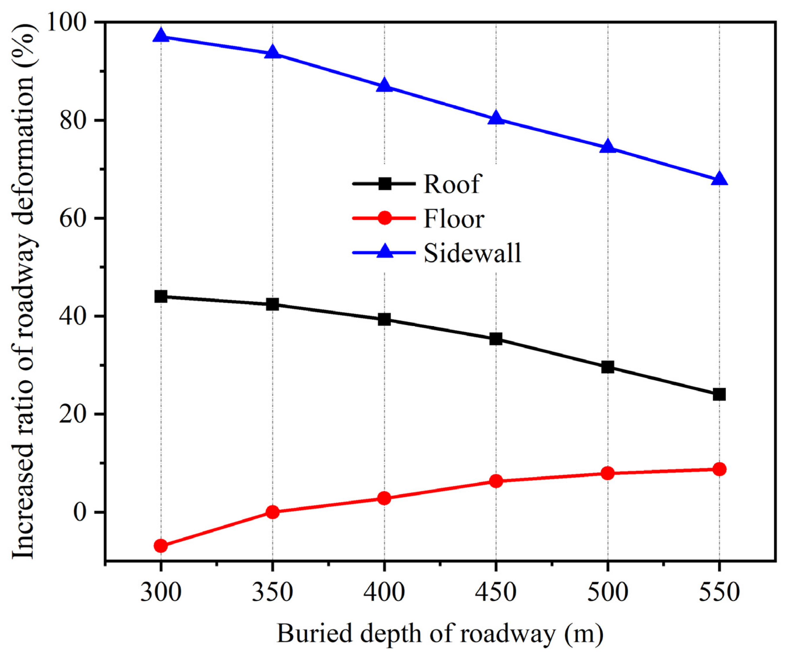
At the same burial depth, the maximum deformation of the roof, floor and side of the roadway with coal–rock interface between the coal seam and roof is greater than that of the roadway without coal–rock interface.
(2)
The increasing range of the maximum deformation of the wall and roof decreases with the increase of the burial depth. The wall deformation of the roadway with interface is larger than that of the roadway without interface, which is equivalent to increasing the span of the roadway roof and the roof deformation. The maximum deformation of the floor increases with the increase of the buried depth.
(3)
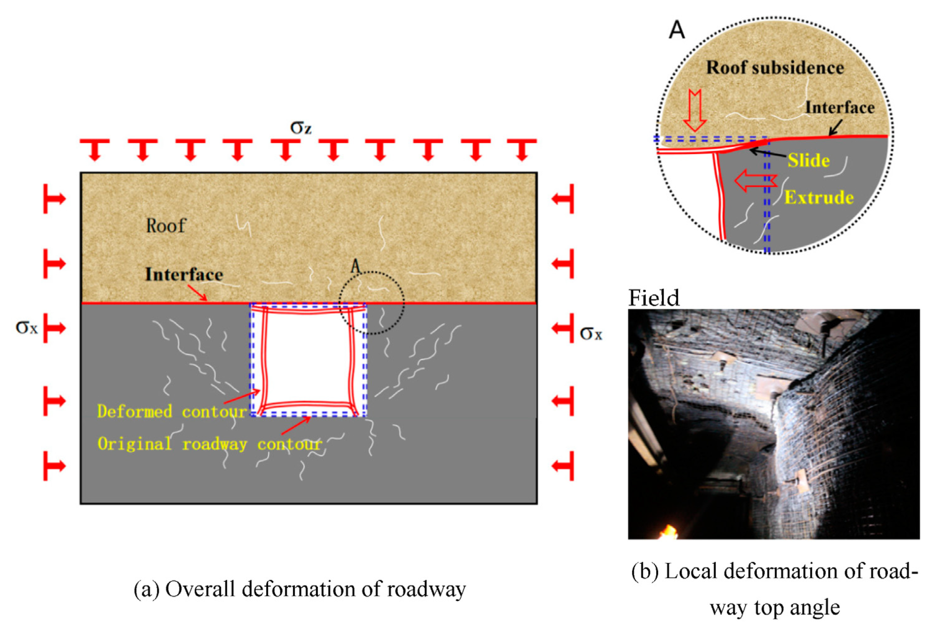
It can be seen from the deformation nephogram that the coal pillar at the deformed side of the roadway without coal–rock interface is well-connected with the roof, and there is no mutual slip and dislocation. However, the slip and dislocation between the coal pillar and the roof at the deformed side of the roadway with coal–rock interface is evident. When the burial depth is large, the side appears to extrude into the roadway as a whole. The roadway forms a triangle extrusion area on the floor, the floor heave range is larger, the floor enters the plastic state prematurely and the maximum deformation of the floor continues to increase.

3. Interface Stiffness and Position

3.1. Interface Stiffness

Figure 12 shows the stress distribution law of roadway roof, floor and left wall surrounding rock. It can be seen that:
(1)
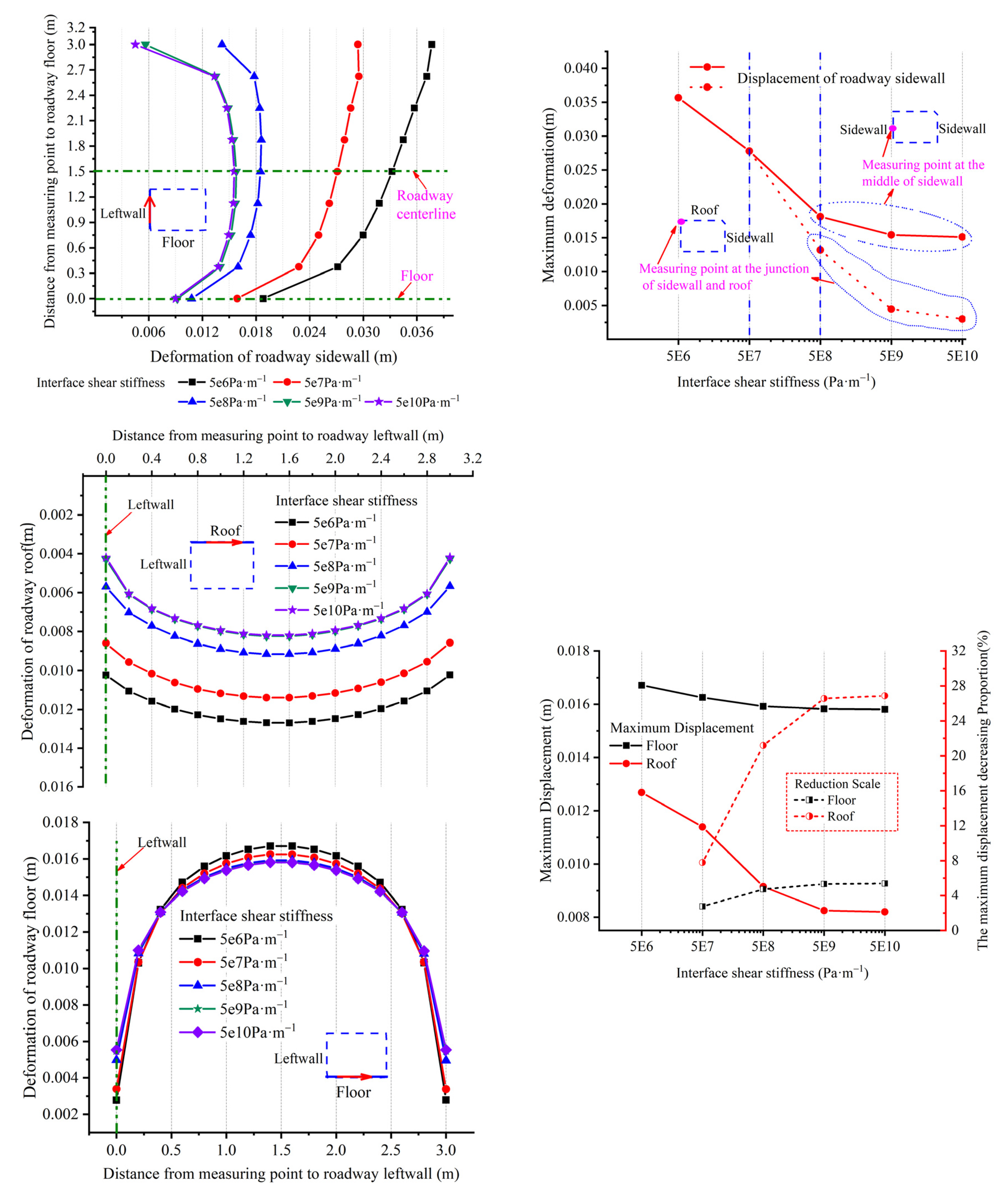
Under different ks values, the surrounding rock stress of the roof, floor and side of roadway decreases first from shallow to deep, then reaches the peak and finally decreases to the original rock stress.
(2)
Near the top of roadway, the smaller the interface stiffness, the lower the stress value. With the increase of the shear stiffness of the interface, the peak stress of the roadway roof and both sides increases first, and then tends to be flat. The distance between the peak point of the roof and the top of roadway gradually shrinks, and the distance between the peak point of wall and the side of roadway is approximately 1.5 m~2.0 m.
(3)
With the increase of the shear stiffness of the interface, the peak stress of the roadway floor decreases gradually, and the peak point is gradually closer to the roadway bottom. The statistics of peak stress and concentration factor of roadway surrounding rock are shown in Table 2.
Figure 13 takes five different shear stiffnesses of interface, and extracts the deformation results of roadway surrounding rock.
The distribution characteristics of the surrounding rock plastic zone can be seen from the figure: the lateral deformation of the roadway wall near the roof is the largest, and the wall deformation at the contact with the floor is the smallest. With the increase of the interface strength, the wall deformation changes from “large up and small down” to “bulging in the middle”. The displacement of the measuring point near the roof at the side is greatly affected by the shear stiffness of the interface. When the stiffness increases, the displacement decreases obviously. When the shear stiffness of the coal–rock interface is 5 GPa·m−1, it is the critical value. When the shear stiffness of the interface is less than 5 GPa·m−1, the displacement of the wall decreases in a linear form with the increase of the strength of the wall top interface. When the stiffness is greater than 5 GPa·m−1, the trend of the displacement reduction decreases. At the same time, with the increase of the shear stiffness of the interface, the deformation of the roadway floor and roof gradually decreases, the shear stiffness is below the critical value and the deformation of the floor and roof decreases greatly.

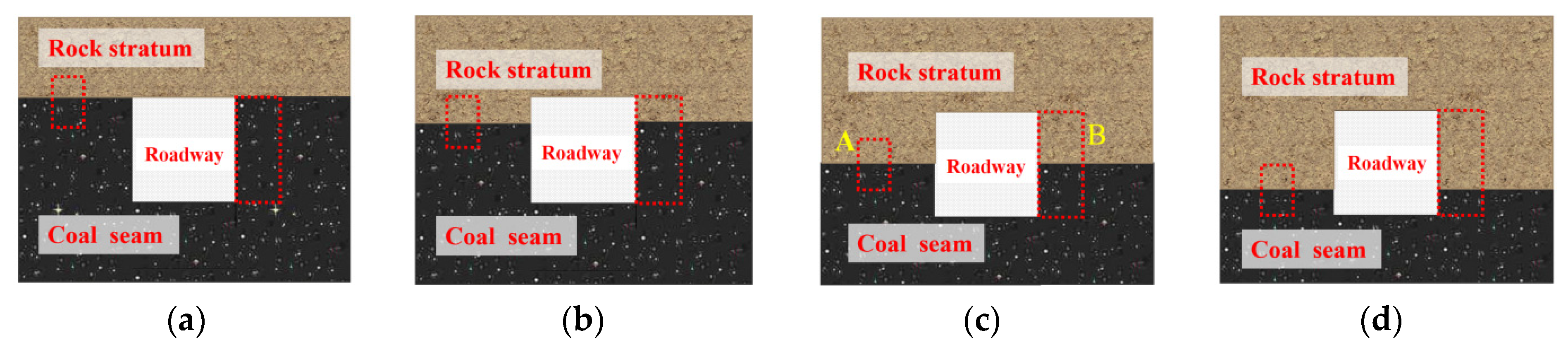
3.2. Interface Position
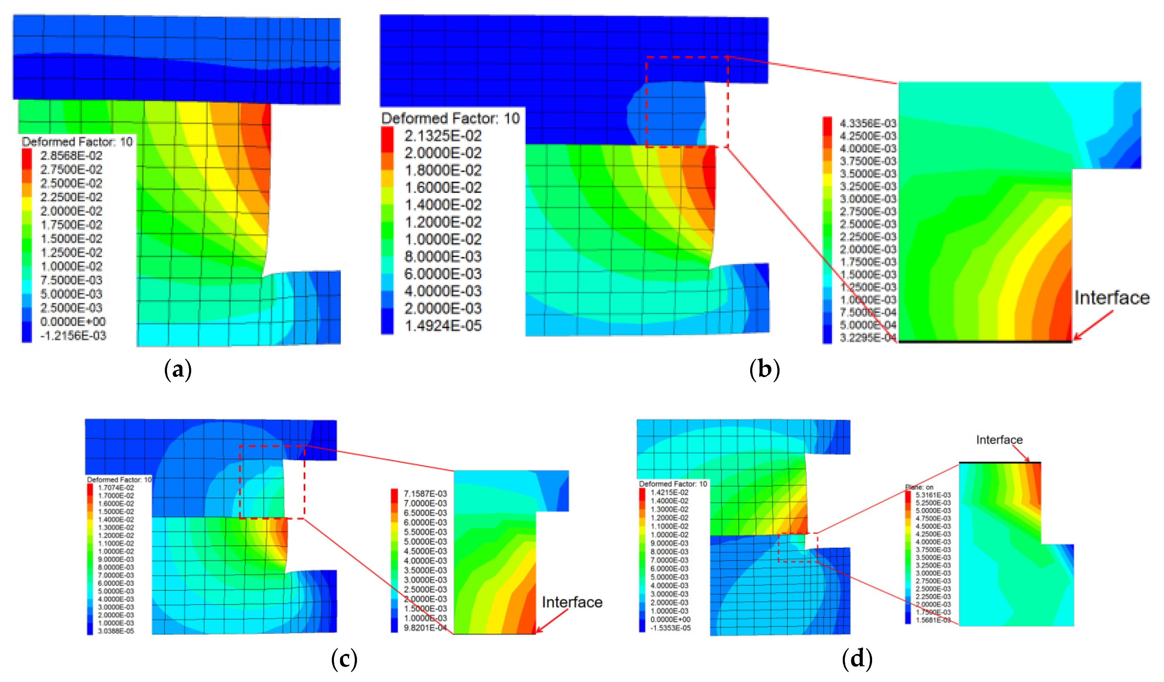
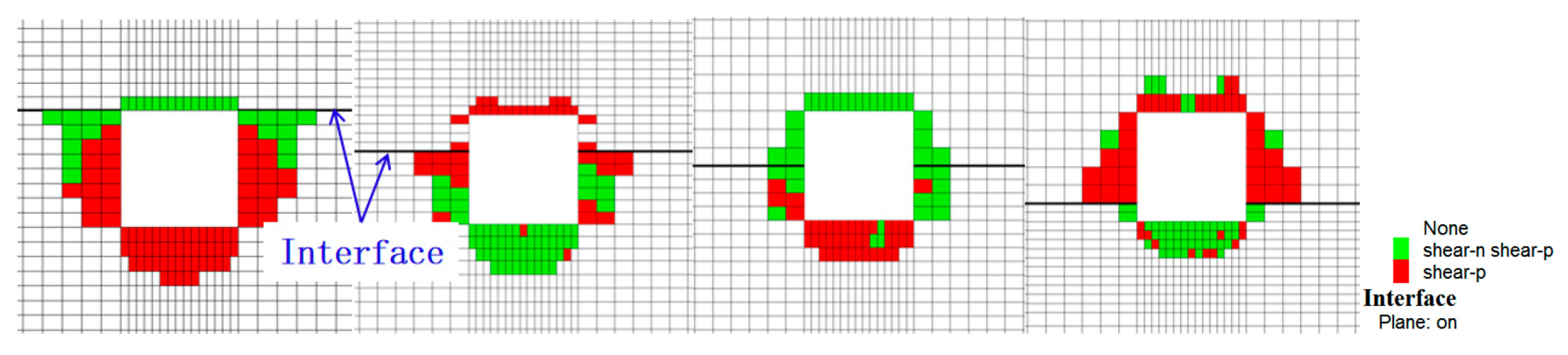
Through the discussion on whether there is interface and the influence of interface shear stiffness on roadway deformation, it can be seen that the interface shear stiffness has a greater influence on the deformation of the roadway wall moving closer, roof subsidence and floor heave. The higher the interface shear stiffness, the more obvious the restriction on roadway deformation. The deformation and stress characteristics of roadways with different coal and rock layer thicknesses are also different. Assuming that there are only two kinds of roadways’ sidewalls, coal seam and rock layer, the distance between the coal seam and rock layer interface and the roadway floor is a and the roadway width and height are still 3 m × 3 m, when a is 3 m, 2 m, 1.5 m and 0.5 m, respectively. Four variables are set according to the proportion of coal seams in the roadway sidewall height, which are full seam roadway, 3/4 seam roadway, 1/2 seam roadway and 1/4 seam roadway. The buried depth of the model is 400 m, the shear stiffness is 0.05 GPa·m−1 and other parameters remain unchanged, as shown in Figure 14.
It can be seen in Figure 15 that:
(1)
When the coal–rock interface is 3 m from the roadway floor and is a full seam roadway, the deformation is relatively continuous, and the deformation gradually decreases from the interface to the bottom of the roadway wall. When the coal–rock interface is between the roof and floor of the roadway, the deformation of the rock part of the slope and the coal part has obvious differences. The deformation is discontinuous at the interface, and there is dislocation between the rock stratum and the coal seam.
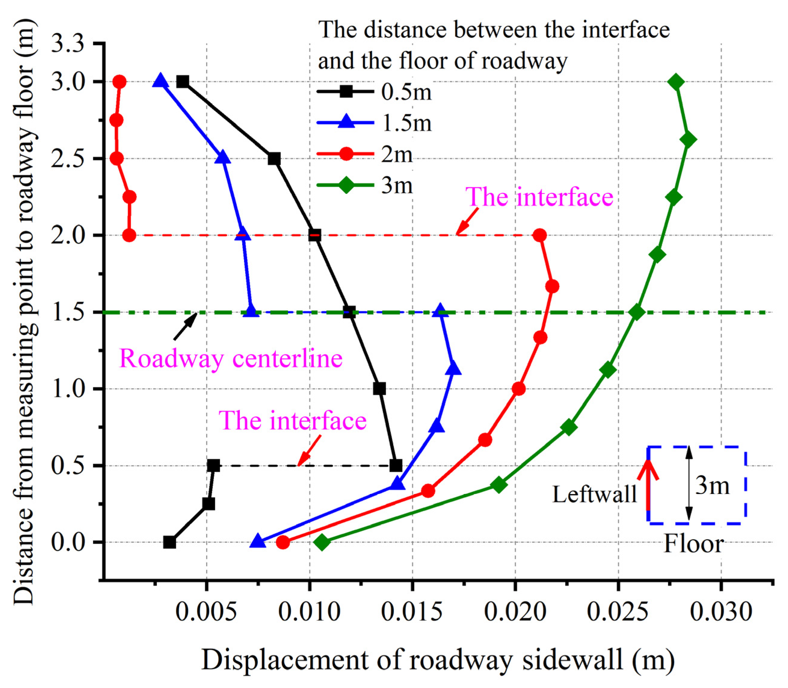
(2)
The larger the proportion of rock in the roadway side, that is, the smaller the value of a, the greater the deformation of rock in the roadway side. On the contrary, the deformation of coal body increases. When a is no less than 1.5 m, the deformation of rock is less than that of the coal body, and the slope is slightly bulged. When the a value is 0.5 m, the deformation of rock mass is greater than that of coal.
(3)
The interface position has little influence on the deformation of the roadway floor, the maximum deformation value is 0.0162 m~0.0166 m and the deformation shape is basically consistent. As the interface is further away from the roadway floor, that is, the greater the value of a, the deformation of the floor slightly increases, and the deformation of the roof gradually increases, with the maximum deformation between 0.006 m and 0.0114 m. The roof deformation is concave, with the largest deformation in the middle and gradually decreasing toward both ends.
Figure 16 shows the cloud diagram of the roadway deformation at different coal–rock interfaces. The deformation forms of the roadway wall at varying coal–rock interfaces are different. When the coal–rock interface is far away from the roadway floor, the lower coal seam accounts for a large proportion, and the coal pillar is prone to deformation and instability. The deformation is greater than the roadway rock mass, and the rock stratum has shear dislocation along the coal–rock interface. When the proportion of coal seams gradually decreases, the rock deformation gradually increases. When the a value is 0.5 m, the maximum deformation of rock stratum is greater than that of coal seams.
Figure 17 shows the distribution of the plastic zone of surrounding rock of roadway at different interface positions. When the interface is 3 m away from the roadway floor, the extension range of the plastic zone of the two sides and the roof is approximately 1.5 m and 0.35 m respectively. The extension range of the plastic zone of the roof is small, but the extension range of the two sides and the floor is large. When the interface is 0.5 m away from the roadway floor, the plastic zones of the two sides and the roof and floor are about 1.5 m, 1 m and 1 m. The damage range of the rock part near the interface is larger, and the plastic zone is smaller near the roof.

4. Discussion

Based on the above discussion on the deformation of surrounding rock of different types of roadways with interfaces, it is found that the deformation difference between coal and rock causes the roadway to show slip and discontinuous deformation between rock strata. Under the condition of roadway coal wall height from full coal to 1/4 coal height, the amount of coal seam slip deformation decreases gradually. The reasons for this phenomenon are as follows: 1. The mechanical properties of coal and rock are different. The lateral deformation of coal body is greater than that of rock. In the absence of constraints between strata, the lateral deformation of coal body becomes larger. 2. When coal is compressed and deformed, the peak strength is low, and plastic deformation occurs first. 3. The plastic deformation makes the coal body have greater lateral deformation, forming macro cracks, as shown in Figure 18.
As far as the site’s rock stratum conditions are concerned, the cohesiveness between different lithology rock strata is low. When the roadway is subject to high stress, due to different lithology and occurrence states, the roadway coal pillar and roof rock will inevitably slip and stagger. As shown in Figure 19, the roadway coal pillar and the roof slip, and the anchor cable tray of the roof has been partially covered by the coal pillar. The roadway presents the situation that the whole coal body in the side is sliding along the bedding plane of the coal bed. The roadway deformation is large, and it is difficult to control effectively.
Therefore, when supporting a roadway containing coal–rock interface, it is difficult to effectively control the overall extrusion of the roadway wall coal body into the roadway by using conventional support methods. It must be considered from the perspective of enhancing the integrity between the coal seam and the rock stratum, such as enhancing the bond and friction strength between the rock stratum and the coal seam bedding plane, or connecting the coal seam and the rock stratum by means of cross-layer anchoring to limit the overall lateral displacement of the roadway wall coal body.

5. Conclusions

This paper aims to provide the deformation and stress change rules of the roadway under the condition of coal–rock interface. Through the analysis of the field deformation, the interface element is introduced into the numerical model, which has the following original results compared with other current research results:
(1)
The stress distribution and deformation of the roadway are closely related to the interface between the coal and rock strata. When there is a coal–rock interface, the vertical stress-concentration area of the sidewall is closer to the floor corner. The slip and dislocation between the coal sidewall and the roof are obvious. The roadway forms a triangular compression area on the floor, and the floor enters the plastic state prematurely. The lateral displacement at the contact between the sidewall and roof is the largest and gradually decreases downward. With the increase of the buried depth, the deformation of the roadway increases gradually, and the difference between the two increases gradually. The maximum wall deformation of coal–rock interface roadway is 1.68 times that of the non-interface roadway.
(2)
With the increase of interface stiffness, the displacement of side, floor and roof decreases obviously. The shear stiffness of the coal–rock interface is 5 GPa·m−1, which is the critical value. When the shear stiffness of the interface is less than 5 GPa·m−1, the displacement of the sidewall decreases in a linear form with the increase of the strength of the coal–rock interface. When the stiffness is greater than 5 GPa·m−1, the trend of the displacement reduction decreases.
(3)
The stress and deformation patterns of the tunnel vary with the location of the interface in the tunnel. When it is a full coal roadway, the deformation decreases gradually from the interface to the floor. When the coal–rock interface is between the roadway roof and floor, the slope is discontinuous deformation, and there is dislocation between the rock stratum and the coal seam. When the coal height is not less than 1/2 of the roadway height, the rock deformation is less than the coal body. When the coal height is 0.5 m, the rock deformation is greater than the coal.
(4)
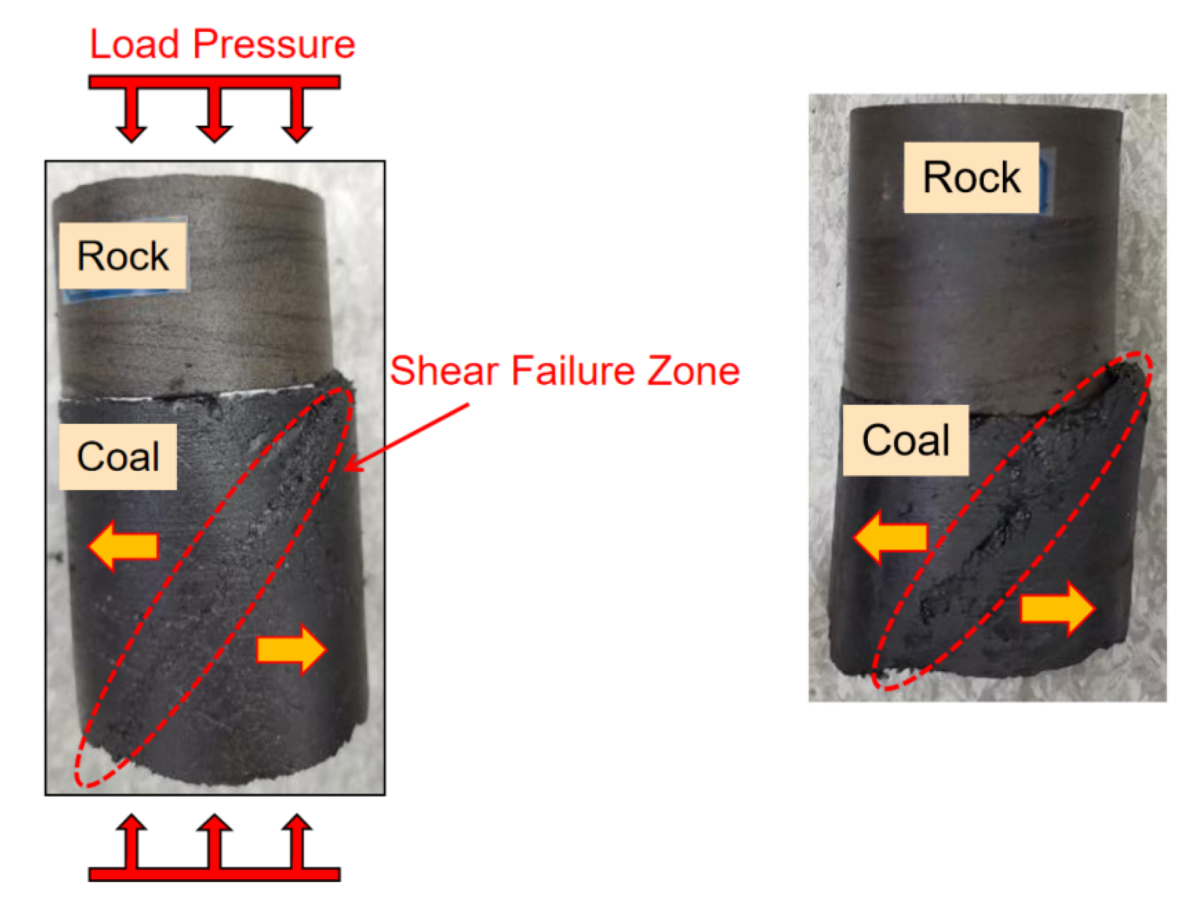
The reason for this deformation of the roadway is that the lateral deformation of the coal sidewall is greater than that of the rock. When the pressure is the same, the lateral deformation of the coal body is greater, and the peak strength of the coal is low. The plastic deformation occurs first, and the plastic deformation makes the coal body have a greater lateral deformation, forming the macro cracks. Therefore, the coal seams and rock strata can be connected to limit the overall lateral movement of the coal body at the side of the roadway by enhancing the bond and friction strength of the rock stratum and the coal seam bedding surface, or by means of cross-layer anchoring.

Author Contributions

T.W. and J.C. conceived and established the experimental system. T.W. and Y.G. wrote the paper. All authors have read and agreed to the published version of the manuscript.

Funding

This research was funded by the Scientific Research Foundation for High-level Talents of Anhui University of Science and Technology (grant number 13210673), the University Natural Science Research Project of Anhui Province (grant number KJ2021A0453), National Natural Science Foundation of China (grant number 52204081, 52174105).

Institutional Review Board Statement

Not applicable.

Informed Consent Statement

Not applicable.

Data Availability Statement

Not applicable.

Acknowledgments

The authors acknowledge the funding by the Scientific Research Foundation for High-level Talents of Anhui University of Science and Technology (13210673), the University Natural Science Research Project of Anhui Province (KJ2021A0453), the National Natural Science Foundation of China, grant number (52204081, 52174105) and the Anhui Province University Collaborative Innovation Project (GXXT-2019-029).

Conflicts of Interest

The authors declare no conflict of interest.

References

  1. Chen, G.; Li, T.; Yang, L.; Zhang, G.; Li, J.; Dong, H. Mechanical properties and failure mechanism of combined bodies with different coal–rock ratios and combinations. J. Min. Strat. Control Eng. 2021, 3, 023522. [Google Scholar] [CrossRef]
  2. Chen, W.; Wan, W.; Zhao, Y.; Peng, W. Experimental Study of the Crack Predominance of Rock-Like Material Containing Parallel Double Fissures under Uniaxial Compression. Sustainability 2020, 12, 5188. [Google Scholar] [CrossRef]
  3. Yu, W.; Wu, G.; Liu, H.; Wang, P.; An, B.; Liu, Z.; Huang, Z.; Liu, F. Deformation characteristics and stability control of soft coal -rock mining roadway in thin coal seam. J. China Coal Soc. 2018, 43, 2668–2678. [Google Scholar] [CrossRef]
  4. Zhao, Z.; Lv, X.; Wang, W.; Tan, Y. Damage evolution of bi-body model composed of weakly cemented soft rock and coal considering different interface effect. Springer Plus 2016, 5, 292–311. [Google Scholar] [CrossRef] [Green Version]
  5. Zuo, J.; Chen, Y.; Cui, F. Investigation on mechanical properties and rock burst tendency of different coal -rock combined bodies. J. China Univ. Min. Technol. 2018, 47, 81–87. [Google Scholar] [CrossRef]
  6. Yin, D.; Chen, S.; Sun, X.; Jiang, N. Strength Characteristics of Roof Rock-Coal Composite Samples with Different Height Ratios Under Uniaxial Loading. Arch. Min. Sci. 2019, 64, 307–319. [Google Scholar] [CrossRef]
  7. Zhao, P.; He, Y.; Li, S.; Lin, H.; Jia, Y.; Yang, E. Coal thickness effect on mechanics and energy characteristics of coal–rock combination model. J. Min. Saf. Eng. 2020, 37, 1067–1076. [Google Scholar] [CrossRef]
  8. Cao, J.; Dai, Q.; Zhou, Y.; Ma, D. Failure mechanism and strength of coal–rock combination bodies considering dip angles and fractal characteristics of interface. J. Cent. South Univ. (Sci. Technol.) 2018, 49, 175–182. [Google Scholar] [CrossRef]
  9. Tian, C.; Sun, H.; Dai, L.; Li, R.; Wang, B.; Cao, J.; Wang, J.; Hu, Q. Experimental study on mechanical properties and energy evolution law of coal–rock composite structure under different interface connection modes. Geofluids 2022, 2022, 1288463. [Google Scholar] [CrossRef]
  10. Liu, X.S.; Tan, Y.L.; Ning, J.G.; Lu, Y.W.; Gu, Q.H. Mechanical properties and damage constitutive model of coal in coal–rock combined body. Int. J. Rock Mech. Min. Sci. 2018, 110, 140–150. [Google Scholar] [CrossRef]
  11. Zhao, Z.; Wang, W.; Wang, L.; Dai, C. Compression-shear strength criterion of coal–rock combination model considering interface effect. Tunn. Undergr. Space Technol. 2015, 47, 193–199. [Google Scholar] [CrossRef]
  12. Wang, M.; Xiao, T.; Gao, J.; Liu, J. Deformation mechanism and control technology for semi coal and rock roadway with structural plane under shearing force. J. Min. Saf. Eng. 2017, 34, 527–534. [Google Scholar] [CrossRef]
  13. Jin, G.; Wang, L.; Zhang, J. Failure characteristics and support technology for deep half coal–rock mining roadway. Saf. Coal Mines 2015, 46, 126–129. [Google Scholar] [CrossRef]
  14. Zhao, T.; Guo, W.; Lu, C.; Zhao, G. Failure characteristics of combined coal–rock with different interfacial angles. Geomech. Eng. 2017, 11, 345–359. [Google Scholar] [CrossRef]
  15. Chang, B.; Liu, X.; Jia, C.; Yan, R. Study on deformation characteristics and deformation mechanism of steep coal rock interbedded roadway. Coal Sci. Technol. 2022, 50, 40–49. [Google Scholar] [CrossRef]
  16. Yang, X.; Sun, D.; Jing, H. Morphological features of shear-formed fractures developed in a rock bridge. Eng. Geol. 2020, 278, 105833. [Google Scholar] [CrossRef]
  17. Yu, W.; Wu, G.; Liu, Z.; Huang, Z.; Liu, F.; Ren, H. Uniaxial compression test of coal–rock-bolt anchorage body and mechanical mechanisms of bolts. Chin. J. Rock Mech. Eng. 2020, 39, 57–68. [Google Scholar] [CrossRef]
  18. Li, W.; Bai, J.; Cheng, J.; Peng, S.; Liu, H. Determination of coal–rock interface strength by laboratory direct shear tests under constant normal load. Int. J. Rock Mech. Min. Sci. 2015, 60–67, 1063–1070. [Google Scholar] [CrossRef]
  19. Liu, Y.; Lu, C.; Xiao, Z.; Guo, Y. Mechanisms Underlying the Slip and Failure of coal–rock Parting-Coal Structures Under Unloading Conditions. Rock Mech. Rock Eng. 2022, 55, 4913–4928. [Google Scholar] [CrossRef]
  20. Jin, G.; Wang, L.; Li, Z.; Zhang, J. Study on the gateway rock failure mechanism and supporting practice of half-coal–rock extraction roadway in deep coal mine. J. Min. Saf. Eng. 2015, 32, 963–967. [Google Scholar] [CrossRef]
  21. Chen, Y.; Liu, H.-L. Development and implementation of Duncan-Chang constitutive model in FLAC3D. Rock Soil Mech. 2007, 28, 2123–2126. [Google Scholar] [CrossRef]
Figure 1. Detection and deformation characteristics of roadway along roof under high stress.
Sustainability 15 05347 g001
Figure 2. Schematic diagram of contact surface unit.
Sustainability 15 05347 g002
Figure 3. Roadway model of the coal–rock interface.
Sustainability 15 05347 g003
Figure 4. Stress distribution of the surrounding rock of the roadway without interface.
Sustainability 15 05347 g004
Figure 5. Vertical stress distribution of the roadway with interface.
Sustainability 15 05347 g005
Figure 6. Tunnel displacement monitoring point.
Sustainability 15 05347 g006
Figure 7. Variation of sidewalls’ displacement with buried depth of roadway, with and without coal–rock interface.
Sustainability 15 05347 g007
Figure 8. Variation of roof displacement with buried depth of roadway with interface.
Sustainability 15 05347 g008
Figure 9. Variation of floor displacement with buried depth of roadway with interface.
Sustainability 15 05347 g009
Figure 10. Distribution characteristics of surrounding rock plastic zone.
Sustainability 15 05347 g010
Figure 11. Influence of interface on the deformation of roadway.
Sustainability 15 05347 g011
Figure 12. Influence of interface stiffness on stress distribution of surrounding rock of roadway.
Sustainability 15 05347 g012
Figure 13. Influence of interface stiffness on deformation of roadway.
Sustainability 15 05347 g013
Figure 14. Four types of roadways based on interface location. (a) Roadway type I; (b) Roadway type II; (c) Roadway type III; (d) Roadway type IV.
Sustainability 15 05347 g014
Figure 15. Deformation law of roadway wall at different interface positions.
Sustainability 15 05347 g015
Figure 16. Horizontal deformation cloud chart of roadway at different interface positions. (a) The distance between the interface and the floor is 3 m, (b) the distance between the interface and the floor is 2 m, (c) the distance between the interface and the floor is 1.5 m and (d) the distance between the interface and the floor is 0.5 m.
Sustainability 15 05347 g016
Figure 17. Influence of interface position on the distribution of the plastic zone in the roadway.
Sustainability 15 05347 g017
Figure 18. Deformation of coal body in coal–rock combination.
Sustainability 15 05347 g018
Figure 19. Deformation form of the roadway with interface.
Sustainability 15 05347 g019
Table 1. Rock stratum parameter selection.
Composite Rock MassE/GPav φ c/MPaLayer Thickness/m
Fine sandstone9.570.25303.125
Medium sandstone7.730.25302.8615
Mudstone6.880.28352.127
Coal1.220.3381.436
Mudstone6.880.28352.125
Fine sandstone9.570.25303.1212
Medium sandstone7.730.25302.865
Table 2. Peak stress and concentration factor of roadway surrounding rock.
Peak Tress/MPa
Factor of Stress Concentration
ks/Pa·m−1
5 × 1065 × 1075 × 1085 × 1095 × 1010
Peak stress in horizontal direction15.6315.1613.8713.4013.53
Factor of stress concentration1.561.521.391.341.35
Peak stress in vertical direction11.9612.0212.2912.7612.86
Factor of stress concentration1.201.201.231.281.29
Disclaimer/Publisher’s Note: The statements, opinions and data contained in all publications are solely those of the individual author(s) and contributor(s) and not of MDPI and/or the editor(s). MDPI and/or the editor(s) disclaim responsibility for any injury to people or property resulting from any ideas, methods, instructions or products referred to in the content.

