

Experimental Study and Theoretical Analysis of Steel–Concrete Composite Box Girder Bending Moment–Curvature Restoring Force
 ,
,
Abstract
:1. Introduction
2. Summary of Test
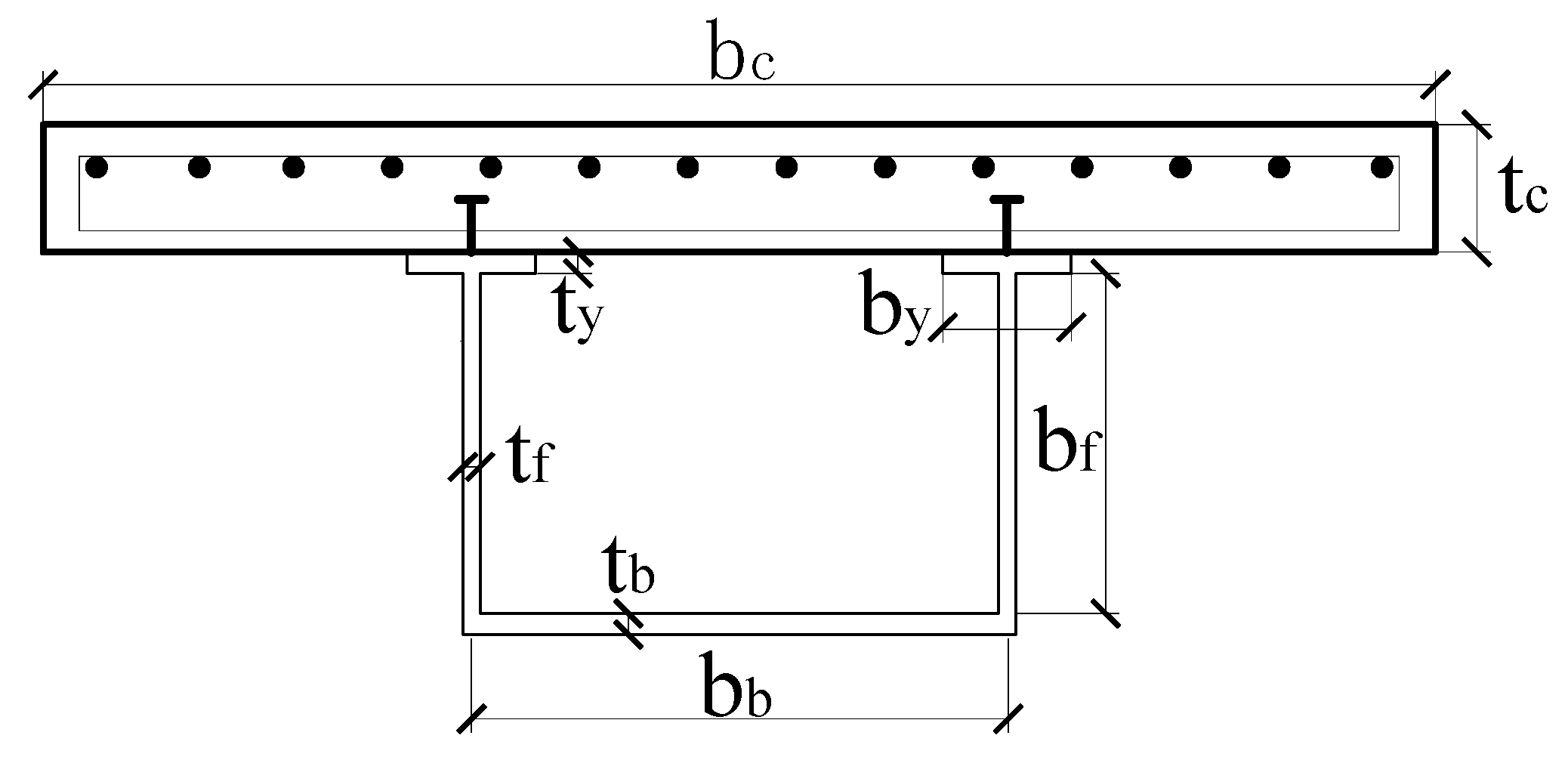
2.1. Specimen Design and Production
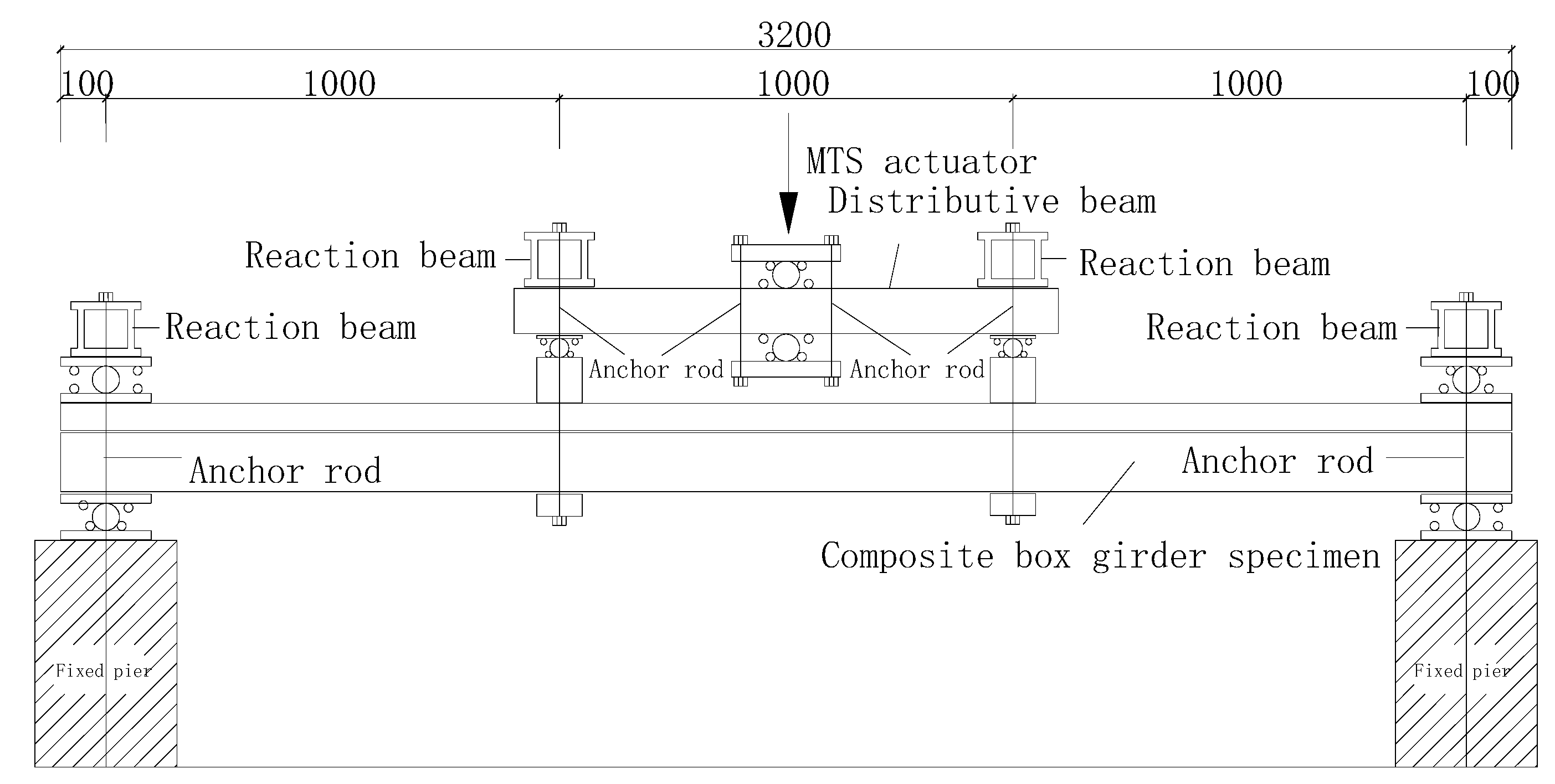
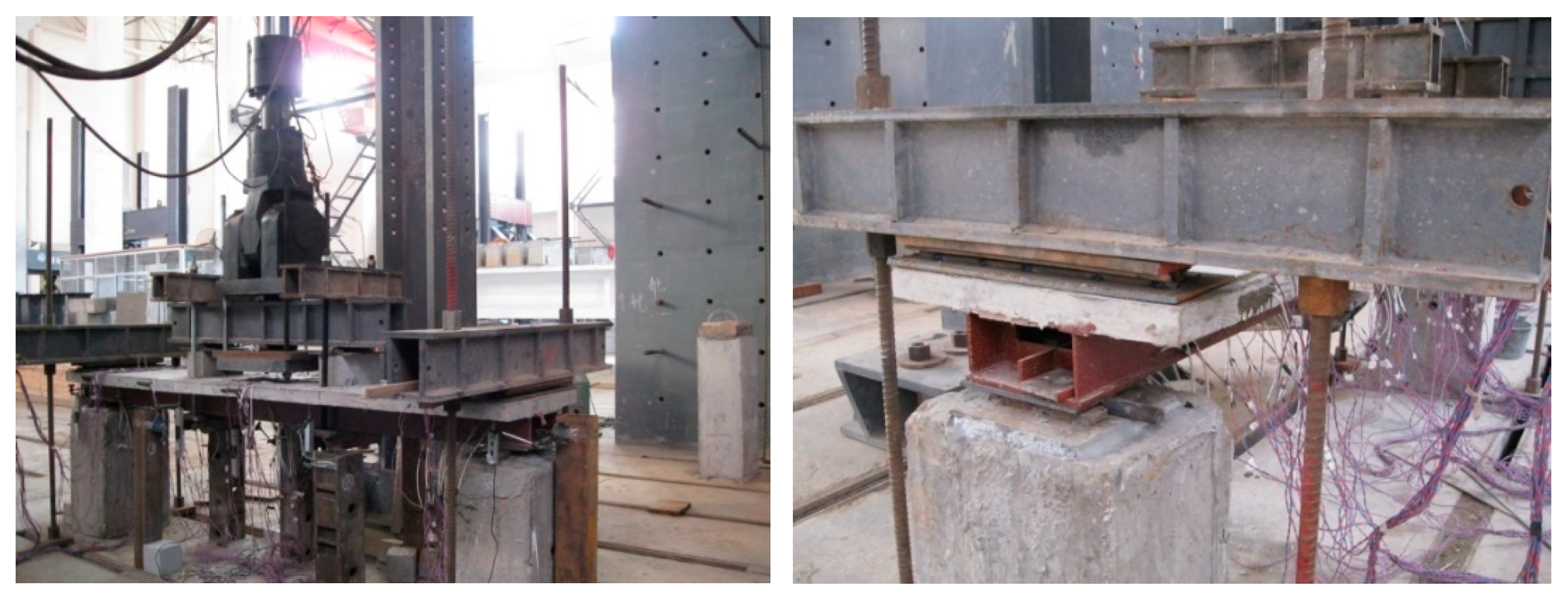
2.2. Test Device
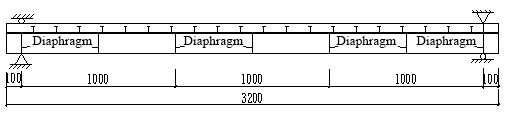
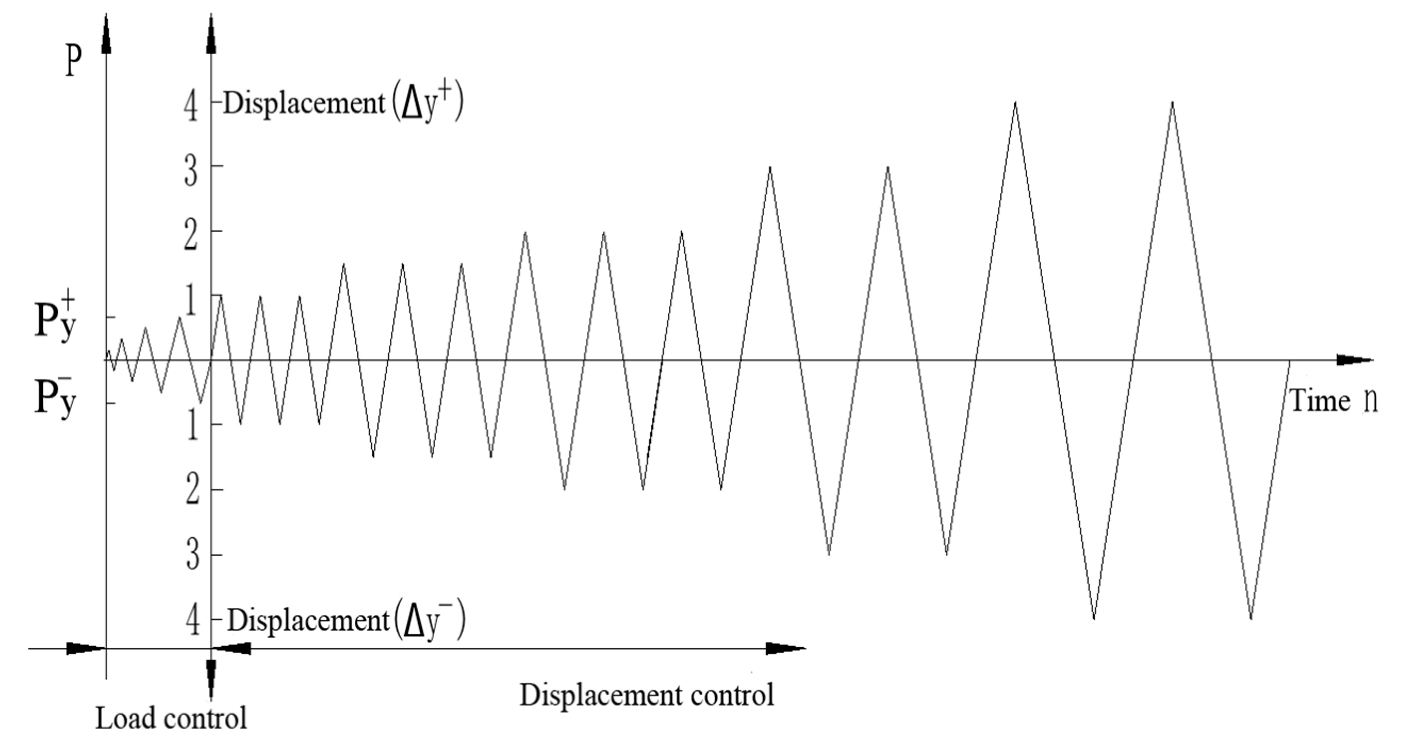
2.3. Loading System
2.4. Test Content
3. Test Results and Analysis
3.1. Failure Mode
3.2. Load–Deflection Hysteresis Curve
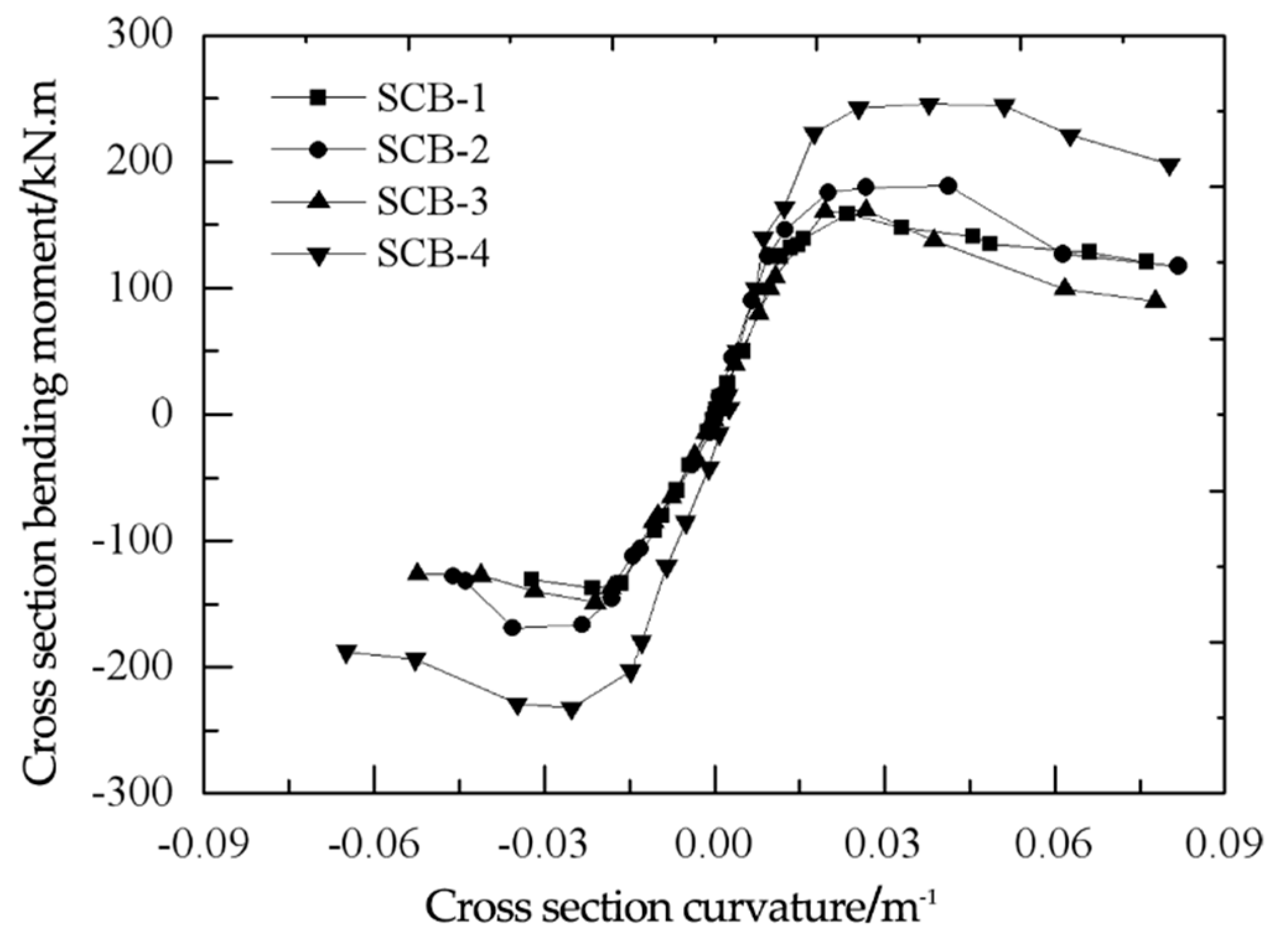
3.3. Bending Moment–Curvature Skeleton Curve
4. Bending Moment–Curvature Restoring Force Model
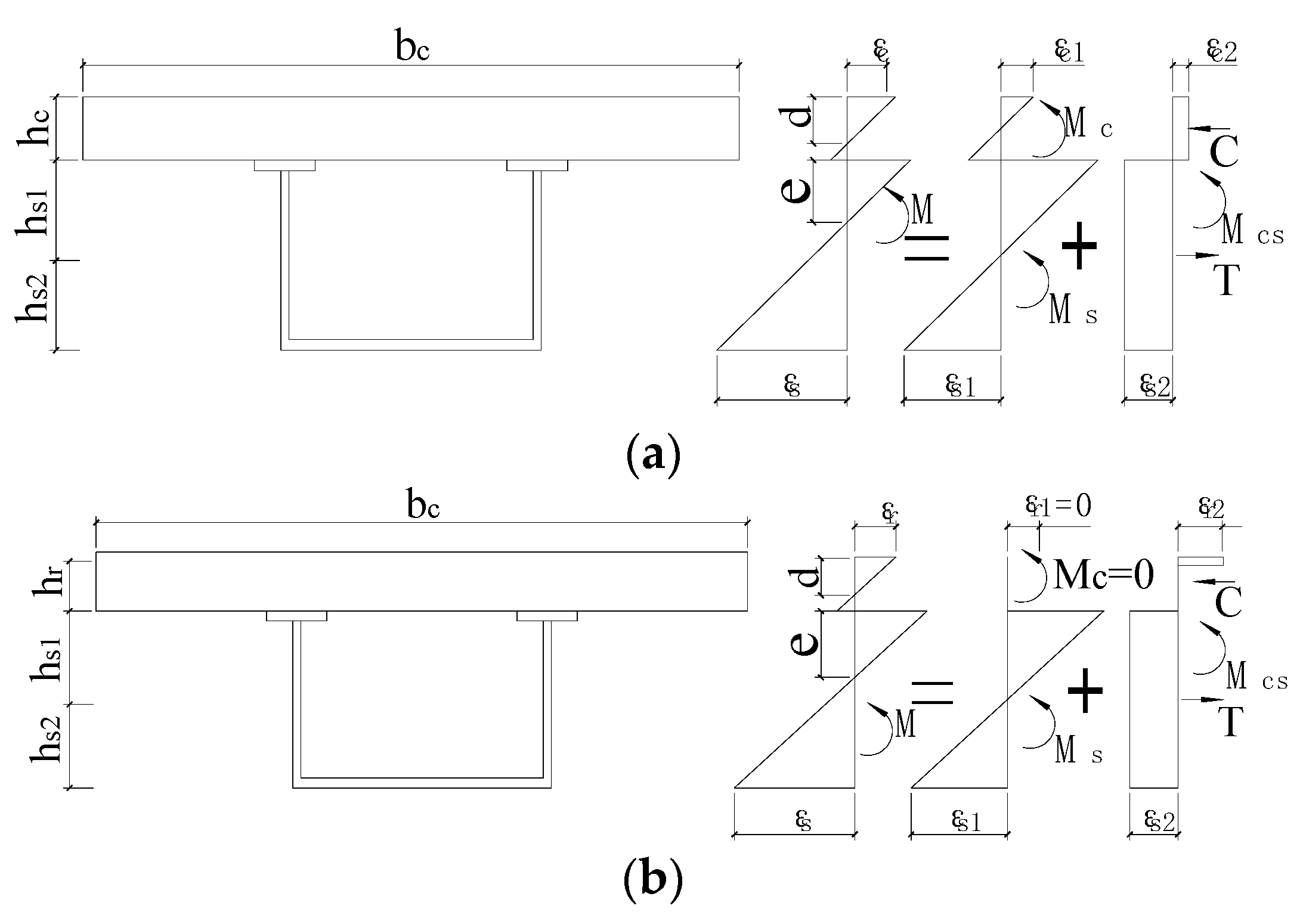
4.1. The Basic Assumptions
- The concrete slab of the tensile zone is not involved in the work;
- The curvature of the steel girder and the concrete slab in the elastic stage is the same as that of the flat section;
- The elastic stiffness of the steel–concrete composite box girder with a partial shear connection is between the elastic stiffness in the case of a complete shear connection and the elastic stiffness in the case of complete non-connection, and assumes that the elastic stiffness can be interpolated by the power function of the shear force in the case of partial shear connections [25].
4.2. Combination Coefficient
- 1.
- Positive bending moment
- 2.
- Negative bending moment
4.3. Yield Moment
- Positive bending moment
- 2.
- Negative bending moment
4.4. Composite Box Girder Bending Moment–Curvature Restoring Force Model
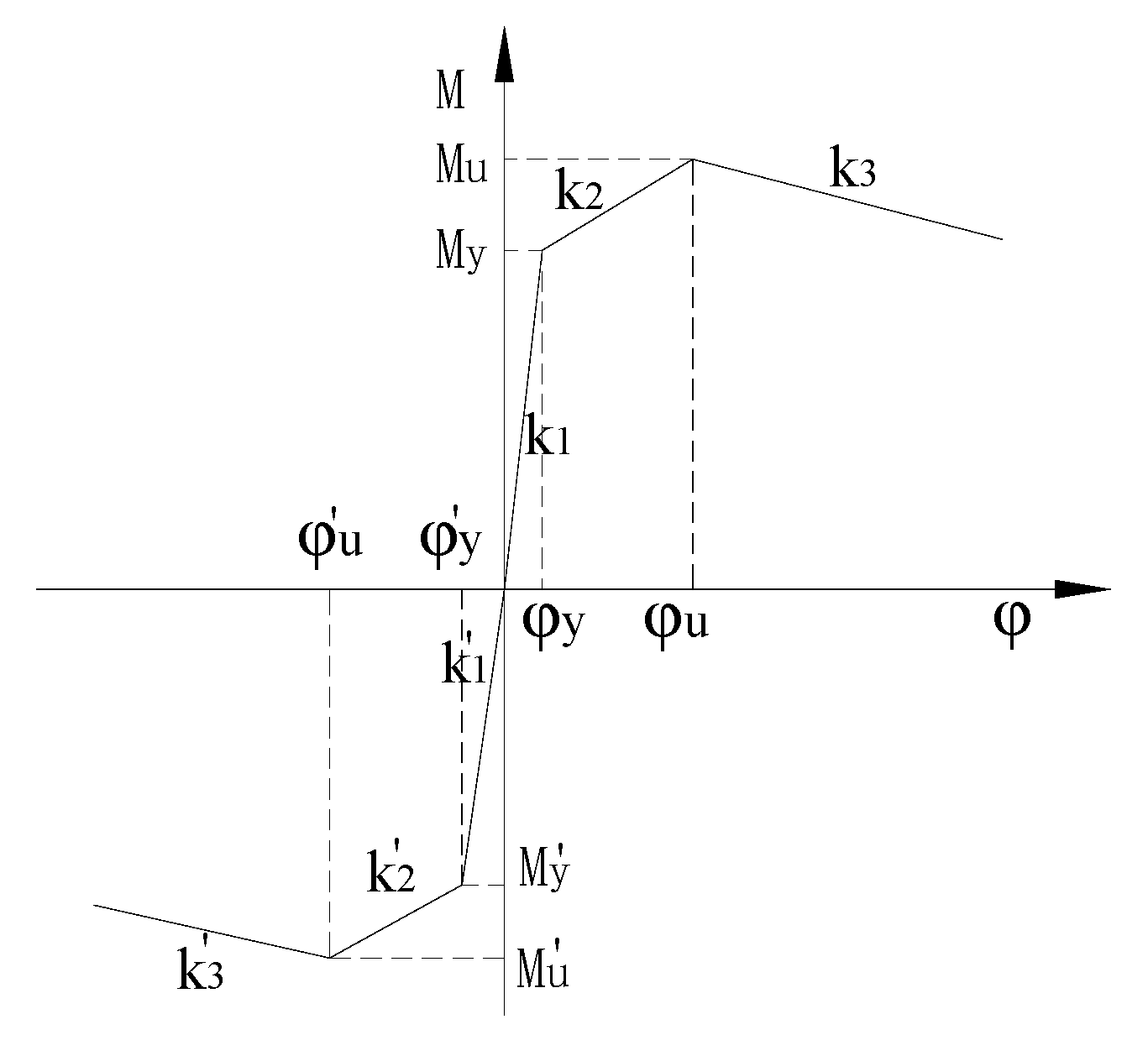
4.4.1. Bending Moment–Curvature Skeleton Curve Model
- 3.
- Positive elastic stiffness
- 4.
- Positive yield bending moment
- 5.
- Positive plastic limit bending moment Mu [30]
- 6.
- Positive reinforcement stiffness
- 7.
- Positive descending slope stiffness k3
- 8.
- Negative elastic stiffness c
- 9.
- Negative yield bending moment
- 10.
- Negative plastic limit bending moment
- 11.
- Negative reinforcement stiffness
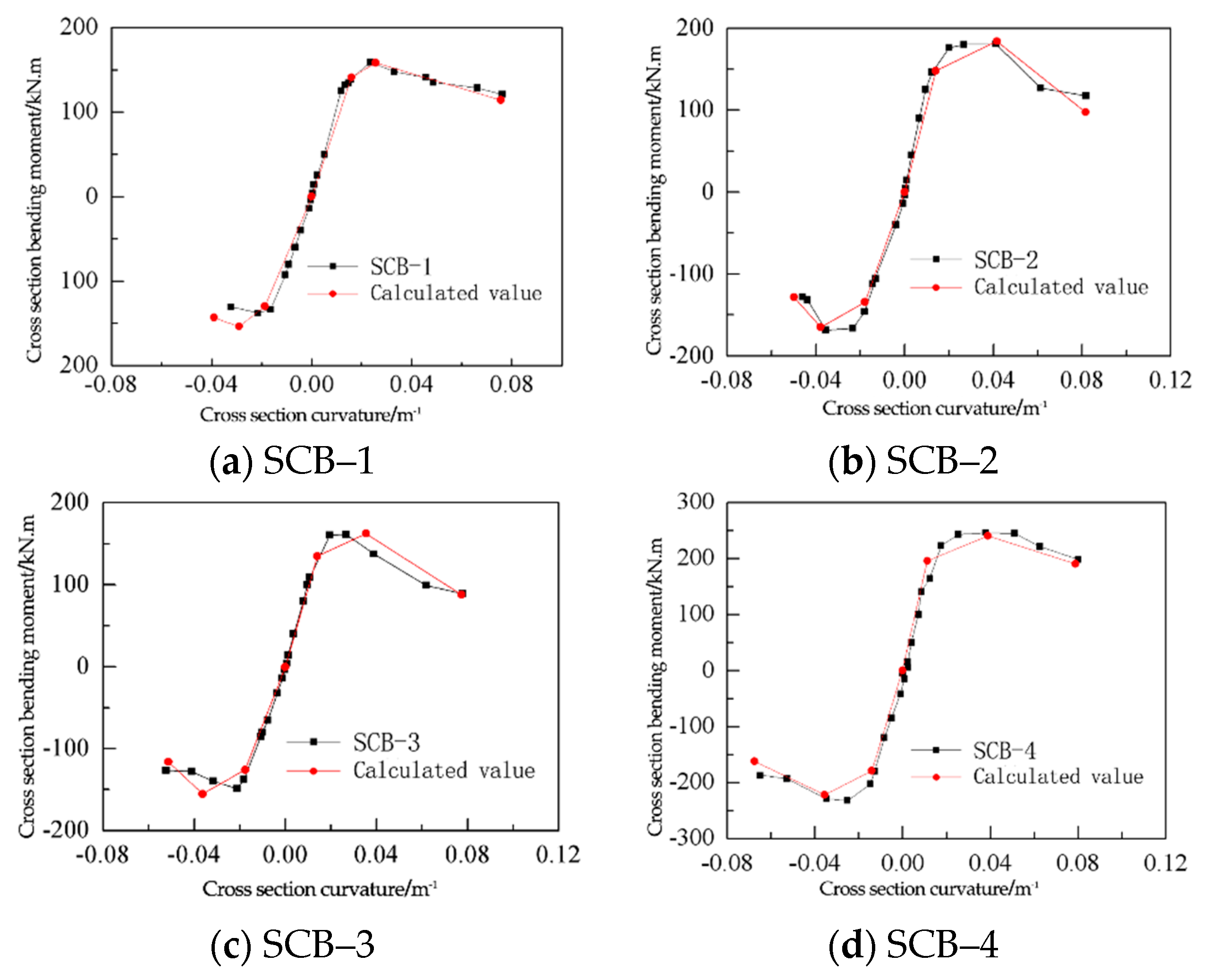
4.4.2. Model Verification of Bending Moment–Curvature Skeleton Curve
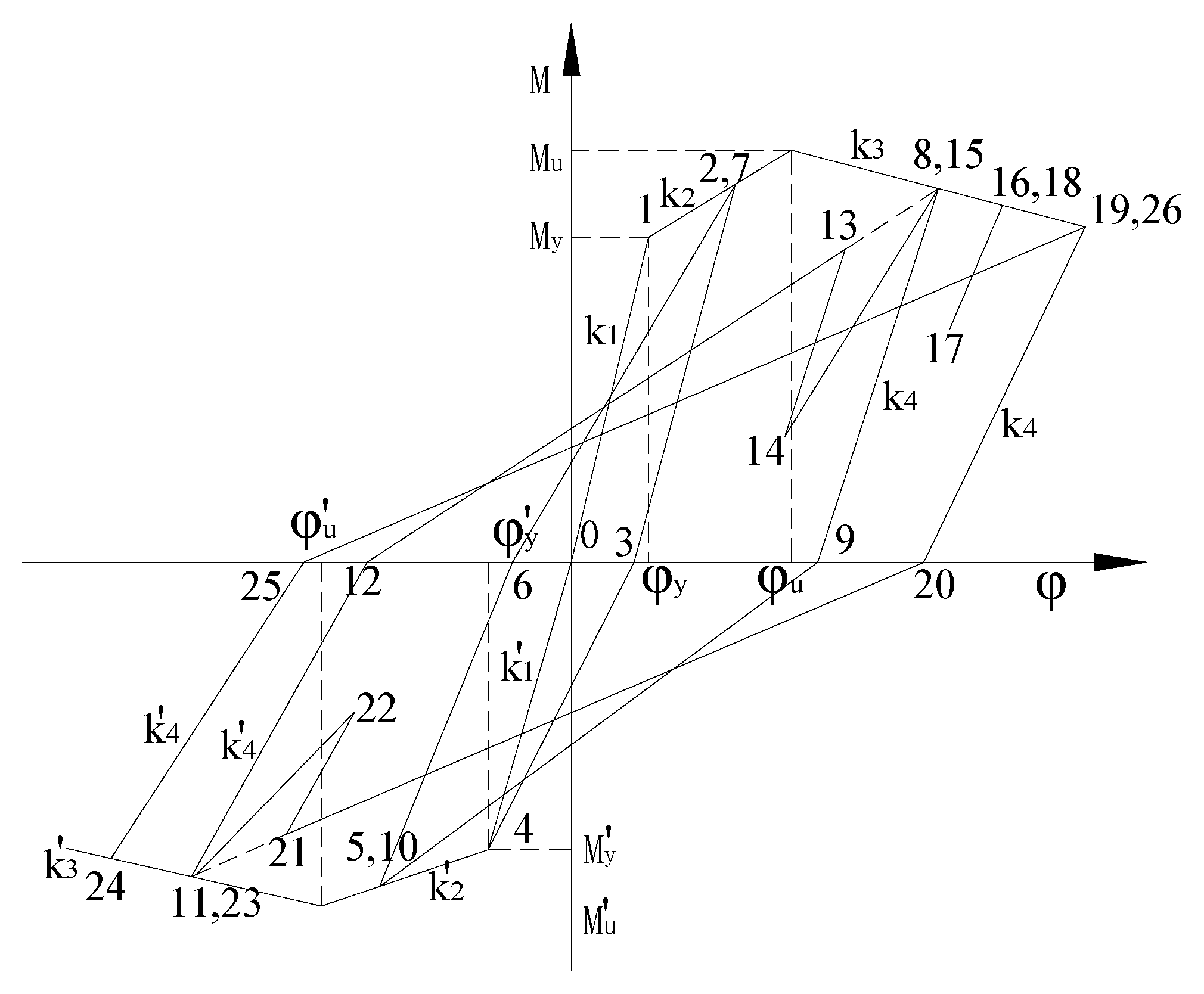
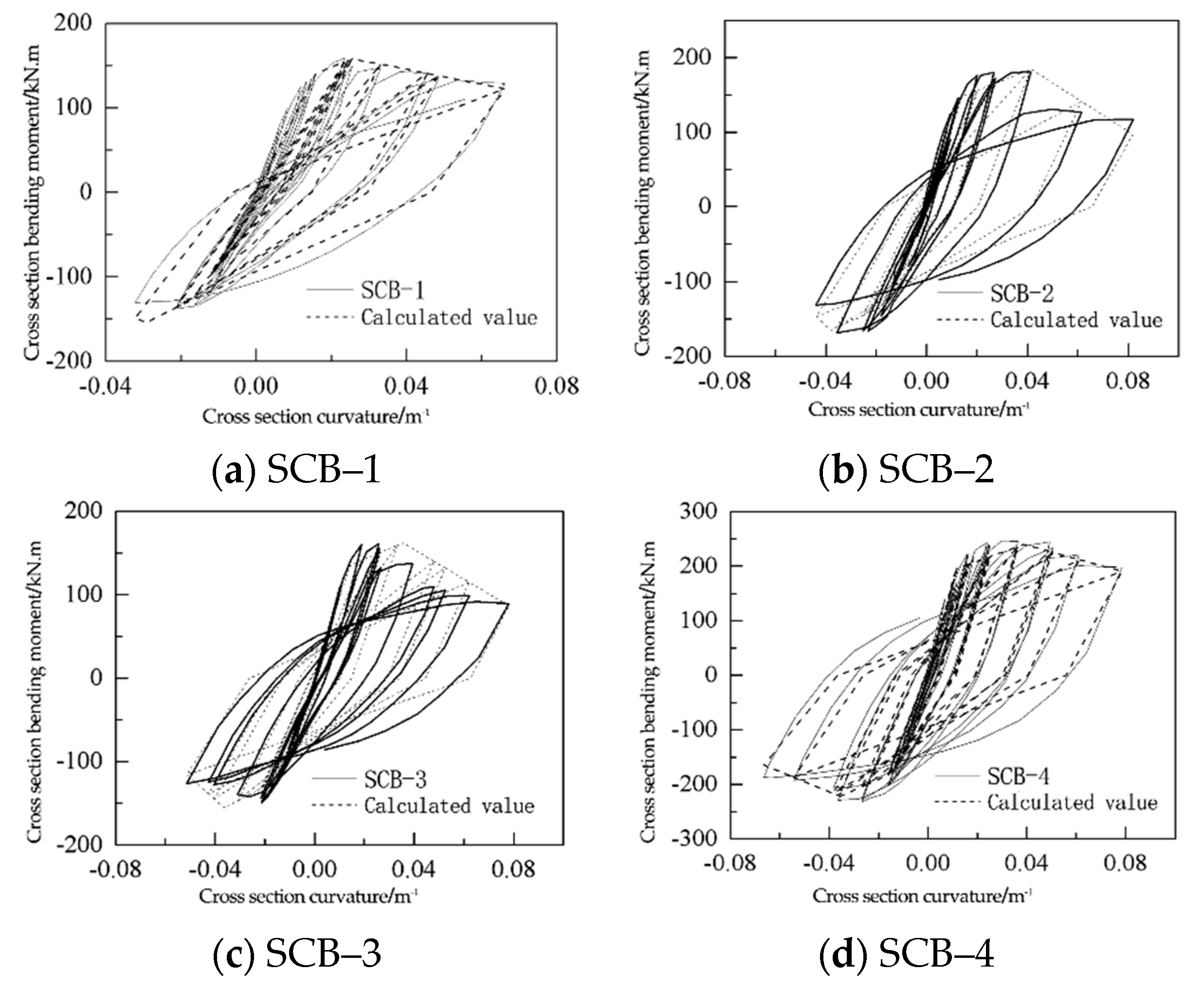
4.4.3. Bending Moment–Curvature Hysteresis Model and Its Verification
5. Conclusions
- (1)
- Composite box girder moment–curvature hysteresis curves can be divided into three stages: elasticity stage, elastoplastic stage, and failure stage. The load–deflection hysteresis rings of composite box girders with different shear connection degrees and height–thickness ratios are plump, and there is no obvious pinching phenomenon, and have good seismic performance.
- (2)
- The skeleton curves of the composite box girder underwent three stages: approximate elasticity stage, elastoplastic stage, and failure stage. Under the same conditions, the frame curve of the composite box girder with a large shear connection is fuller and the seismic performance is better. The skeleton curves have long approximate platform segments in the positive direction and short approximate platform segments in the negative direction, indicating that the positive deformation capacity of the composite box girder is much stronger than the negative deformation capacity, and the positive ductility ratio of the composite box girder is much greater than the negative ductility ratio. The positive and negative ductility ratios of composite box girders increase obviously with the increase of height–thickness ratio.
- (3)
- The influence of the shear connection degree on the bending stiffness of composite box girders is considered by using the power function interpolation method, and the calculation method of forward and negative cross section bending moment–curvature elastic stiffness of the composite box girder considering interface slips is put forward. Moreover, the expression of the bending moment of the section yield is obtained, and the accuracy of the method is verified by comparison with the test results. A three-fold model of the bending moment–curvature skeleton curve of steel–concrete composite box girder sections is established and compared with the experimental results in this paper. The calculation model is in good agreement with the experimental structure, and the calculation method of the model is simple and convenient for engineering applications.
- (4)
- On the basis of experimental data and theoretical analysis, the expressions of the positive and negative stiffness degradation of composite box girders were put forward, and the pointing hysteretic model of the bending moment–curvature degradation vertex of steel–concrete composite box girders was established. The calculated curve of the model was in good agreement with the experimental curve, and the calculation method of the model was simple and clear, convenient for hand calculation, and suitable for engineering applications.
Author Contributions
Funding
Institutional Review Board Statement
Informed Consent Statement
Data Availability Statement
Conflicts of Interest
References
- Nie, J.G. Structure of Steel–Concrete Composite Beam-Test: Theory and Application; Science Press: Beijing, China, 2005; pp. 1–36. [Google Scholar]
- Nie, J.G. Principles and Examples of Steel–Concrete Composite Structure: Theory and Application; Science Press: Beijing, China, 2009. [Google Scholar]
- Daniels, J.H.; Kroll, G.D.; Fisher, J.W. Behavior of composite-beam to column joints. J. Struct. Div. 1970, 96, 671–685. [Google Scholar] [CrossRef]
- Humar, J.L. Composite Beams under Cyclic Loading. ASCE J. Struct. Div. 1979, 105, 1949–1965. [Google Scholar] [CrossRef]
- Gowda, S.S.; Hassinen, P. Behavior of steel–concrete composite members for arctic offshore structures. In Proceedings of the First International Offshore and Polar Engineering Conference, Edinburgh, UK, 11 August 1991; pp. 548–555. [Google Scholar]
- Taplin, G.; Grundy, P. Steel–concrete composite beams under repeated load. In Proceedings of the Conference: Composite Construction in Steel and Concrete IV, Banff, AB, Canada, 28 May–2 June 2000; pp. 37–50. [Google Scholar]
- Nie, J.G.; Yu, Z.L.; Ye, Q.H. Seismic behavior of composite steel–concrete beams. J. Tsinghua Univ. (Sci. Tech.) 1998, 38, 35–37. [Google Scholar]
- Nie, J.G.; Yu, Z.L.; Yuan, Y.S. Research on restoring force model of composite steel–concrete beams. J. Tsinghua Univ. (Sci. Tech.) 1999, 39, 121–123. [Google Scholar]
- Nie, J.G.; Huang, Y. Nonlinear model for seismic analysis of steel–concrete composite beams. J. Tsinghua Univ. (Sci. Tech.) 2009, 49, 329–332. [Google Scholar]
- Zhou, W.B. Static and Dynamic Performance of Steel–Concrete Composite Box-Beam and Frame structure. Ph.D. Thesis, Central South University, Changsha, China, 2013. [Google Scholar]
- Zhou, W.B.; Jiang, L.Z.; Li, S.J.; Kong, F. Finite element time history analysis on seismic response of steel–concrete composite frame structure. J. Huazhong Univ. Sci. Technol. (Nat. Sci. Ed.) 2014, 42, 61–65. [Google Scholar]
- Qi, J.J.; Jiang, L.Z.; Zhou, W.B. Restoring force model of steel–concrete composite frame structure. J. Cent. South Univ. (Sci. Technol.) 2013, 44, 3863–3872. [Google Scholar]
- Ayoub, A.; Filippou, F.C. Mixed formulation of nonlinear steel–concrete composite beam element. J. Struct. Eng. 2000, 126, 371–381. [Google Scholar] [CrossRef]
- Jiang, L.Z.; Yu, Z.W.; Cao, H. Research on restoring force model of steel–concrete composite beams. Ind. Constr. 2007, 37, 85–88. [Google Scholar]
- Xin, X.Z.; Jiang, L.Z.; Cao, H. Research of restoring force model on steel–concrete composite continuous beams. J. Build. Struct. 2006, 27, 83–89. [Google Scholar]
- Jiang, L.Z. Study on seismic performance of steel–concrete composite box girder with corrugated web. J. Railw. Sci. Eng. 2021, 18, 555–563. [Google Scholar]
- Gattesco, N.; Giuriani, E. Experiment study on stud shear connectors subjected to cyclic loading. J. Constr. Steel Res. 1996, 38, 1–21. [Google Scholar] [CrossRef]
- Gattesco, N.; Giuriani, E.; Gubana, A. Low–cycle fatigue test on stud shear connectors. J. Struct. Eng. 1997, 123, 145–150. [Google Scholar] [CrossRef]
- Taplin, G.; Grundy, P. Incremental slip of stud shear connectors under repeated loading. In Proceedings of the Composite Construction Conventional and Innovative, International Conference, Innsbruckm, Austria, 16–18 September 1997. [Google Scholar]
- Liu, J. Energy dissipation of steel–concrete composite beams subjected to vertical cyclic loading. Adv. Steel Constr. 2022, 18, 658–669. [Google Scholar]
- Ding, F.X. Experimental investigation on hysteretic behavior of simply supported steel–concrete composite beam. J. Constr. Steel Res. 2018, 144, 153–165. [Google Scholar]
- Zhou, W.B. Experiment of seismic performance for steel–concrete composite box-beam. J. Traffic Transp. Eng. 2014, 14, 1–9. [Google Scholar]
- DL/T 5085-1999; Steel—Concrete Composite Structure Design Code. Industrial Construction: Beijing, China, 1999.
- Li, G.Q.; Cui, D.G. Experimental study on the restoring force model of shear wall supported on the frame with steel reinforcing. J. Build. Struct. 2008, 29, 73–80. [Google Scholar]
- Lam, D.; Ei-lobod, E. Behavior of headed stud shear connectors in composite beam. J. Struct. Eng. ASCE 2005, 131, 96–107. [Google Scholar] [CrossRef]
- Guo, Z.Y. Experimental and Theoretical Research on Bending Properties of Steel—Concrete Simple Supported Composite Beams. Master’s Thesis, Xi’an University of Architecture and Technology, Xi’an, China, 2007. [Google Scholar]
- AISC Committee. Specification for Structural-Steel Buildings (ANSI/AISC 360-10); AISC: Chicago, IL, USA, 2010. [Google Scholar]
- Nie, J.G.; Tan, Y.; Wang, H.Q. Strength of stud shear connectors in composite steel-HC beams. J. Tsinghua Univ. (Sci. Tech.) 1999, 39, 94–97. [Google Scholar]
- Shi, W.L. Experimental and Theoretical Study on Semirigid Beam-to-Column Composite Joints with Flush End-Plate Connection. Ph.D. Thesis, Tongji University, Shanghai, China, 2006. [Google Scholar]
- Nie, J.G.; Cui, Y.P.; Shi, Z.Z.; Liu, Q.; Guo, S.B. Ultimate flexural capacity of composite steel–concrete beams with partial shear connection. Eng. Mech. 2000, 17, 37–42. [Google Scholar]
- Rchard Liew, J.Y.; Hong, C.; Shanmugam, N.E. Inelastic analysis of steel frames with composite beams. J. Struct. Eng. 2001, 127, 194–204. [Google Scholar] [CrossRef]
- Fan, J.S.; Nie, J.G. Effects of slips on load-carrying capacity of composite beams under negative bending. Eng. Mech. 2005, 22, 177–182. [Google Scholar]


| Serial Number | SCB-1 | SCB-2 | SCB-3 | SCB-4 |
|---|---|---|---|---|
| Span | 3000 | 3000 | 3000 | 3000 |
| 650 | 650 | 650 | 650 | |
| 60 | 60 | 60 | 60 | |
| 60 × 9.42 | 60 × 9.42 | 60 × 9.42 | 60 × 9.42 | |
| 280 × 9.42 | 280 × 9.42 | 280 × 9.42 | 280 × 9.42 | |
| 115 × 7.22 | 117 × 7.22 | 116 × 3.36 | 162 × 7.22 | |
| 12.8 | 12.8 | 12.8 | 12.8 | |
| 130 | 90 | 90 | 90 | |
| 15.9 | 16.2 | 34.5 | 22.4 | |
| 0.44 | 0.71 | 0.66 | 0.64 | |
| Stirrup | 22Φ6 | 22Φ6 | 22Φ6 | 22Φ6 |
| Longitudinal bar | 13Φ13.4 | 13Φ13.4 | 13Φ13.4 | 13Φ13.4 |
| Steel Category | |||
|---|---|---|---|
| 4 mm Steel plate | 369 | 465 | 206,000 |
| 8 mm Steel plate | 273 | 400 | 200,000 |
| 10 mm Steel plate | 301 | 420 | 209,000 |
| Φ14 reinforced | 459 | 560 | 206,000 |
| Φ6 reinforced | 550 | 680 | 200,000 |
| Φ13 stud | 350 | 435 | 206,000 |
Disclaimer/Publisher’s Note: The statements, opinions and data contained in all publications are solely those of the individual author(s) and contributor(s) and not of MDPI and/or the editor(s). MDPI and/or the editor(s) disclaim responsibility for any injury to people or property resulting from any ideas, methods, instructions or products referred to in the content. |
© 2023 by the authors. Licensee MDPI, Basel, Switzerland. This article is an open access article distributed under the terms and conditions of the Creative Commons Attribution (CC BY) license (https://creativecommons.org/licenses/by/4.0/).
Share and Cite
Qi, J.; Ye, Y.; Huang, Z.; Lv, W.; Zhou, W.; Liu, F.; Wu, J. Experimental Study and Theoretical Analysis of Steel–Concrete Composite Box Girder Bending Moment–Curvature Restoring Force. Sustainability 2023, 15, 6585. https://doi.org/10.3390/su15086585
Qi J, Ye Y, Huang Z, Lv W, Zhou W, Liu F, Wu J. Experimental Study and Theoretical Analysis of Steel–Concrete Composite Box Girder Bending Moment–Curvature Restoring Force. Sustainability. 2023; 15(8):6585. https://doi.org/10.3390/su15086585
Chicago/Turabian StyleQi, Jingjing, Yining Ye, Zhi Huang, Weirong Lv, Wangbao Zhou, Fucai Liu, and Jidong Wu. 2023. "Experimental Study and Theoretical Analysis of Steel–Concrete Composite Box Girder Bending Moment–Curvature Restoring Force" Sustainability 15, no. 8: 6585. https://doi.org/10.3390/su15086585