Article

A Bidirectional Grid-Friendly Charger Design for Electric Vehicle Operated under Pulse-Current Heating and Variable-Current Charging

1
School of Electrical & Electronic Engineering, Harbin University of Science and Technology, Harbin 150080, China
2
School of Vehicle and Mobility, Tsinghua University, Beijing 100084, China
3
School of Electrical Engineering, Hebei University of Technology, Tianjin 300401, China
*
Author to whom correspondence should be addressed.
Sustainability 2024, 16(1), 367; https://doi.org/10.3390/su16010367
Submission received: 31 October 2023 / Revised: 20 December 2023 / Accepted: 28 December 2023 / Published: 30 December 2023

Abstract

:
Low-temperature preheating, fast charging, and vehicle-to-grid (V2G) capabilities are important factors for the further development of electric vehicles (EVs). However, for conventional two-stage chargers, the EV charging/discharging instructions and grid instructions cannot be addressed simultaneously for specific requirements, pulse heating and variable-current charging can cause high-frequency power fluctuations at the grid side. Therefore, it is necessary to design a bidirectional grid-friendly charger for EVs operated under pulse-current heating and variable-current charging. The DC bus, which serves as the medium connecting the bidirectional DC–DC and bidirectional DC–AC, typically employs capacitors. This paper analyzes the reasons why the use of capacitors in the DC bus cannot satisfy the grid and EV requirements, and it proposes a new DC bus configuration that utilizes energy storage batteries instead of capacitors. Due to the voltage-source characteristics of the energy storage batteries, EV instructions and grid instructions can be flexibly and smoothly scheduled by using phase-shift control and adaptive virtual synchronous generator (VSG) control, respectively. In addition, the stability of the control strategy is demonstrated using small signal modeling. Finally, typical operating conditions (such as EV pulse preheating, fast charging with variable current, and grid peak shaving and valley filling) are selected for validation. The results show that in the proposed charger, the grid scheduling instructions and EV charging/discharging instructions do not interfere with each other, and different commands between EVs also do not interfere with each other under a charging pile with dual guns. Without affecting the requirements of EVs, the grid can change the proportion of energy supply based on actual scenarios and can also obtain energy from either EVs or energy storage batteries. For the novel charger, the pulse modulation time for EVs consistently achieves a steady state within 0.1 s; thus, the pulse modulation speed is as much as two times faster than that of conventional chargers with identical parameters.

1. Introduction

In order to address climate change and energy crises, the integration of new energy sources such as wind and photovoltaic is booming [1]. The performance and sales volumes of electric vehicles (EVs) have been continuously increasing. However, new challenges have emerged both on the grid side and the EV side. For the grid side, the increasing number of EVs imposes significant load pressures during peak charging periods. The intermittent, random, and uncertain nature of renewable energy sources hinders optimal matching between the power generation and consumption sides of the power system [2,3]. Consequently, the power system exhibits a characteristically high proportion of renewable energy and high proportion of power electronics [4]. As a result, the new power system faces challenges such as a decline in inertial support capability and inadequate frequency and voltage regulation capacities [5,6]. Vehicle-to-grid (V2G) is recognized as a crucial solution to these changes. This because EVs, as mobile energy storage units, remain parked for considerable periods of time, thereby presenting abundant potential for energy dispatch [7]. Through bidirectional charging, EVs can help the grid to shave peaks and fill valleys. Furthermore, EVs can also be extended to various scenarios such as vehicle-to-building (V2B), vehicle-to-vehicle (V2V), vehicle-to-subway (V2S), and vehicle-to-load (V2L) [8]. For the EV side, the inadequate vehicle-to-charger ratio and slow charging speed hinder the rapid advancement and mobility of EVs [9]; moreover, in cold environmental conditions, the impaired performance of the power battery hampers the proper initiation of EVs [10]. In order to overcome these anxieties surrounding driving ranges and charging, it is imperative to research and develop fast chargers with low-temperature preheating functions.
The current during fast charging is a dynamic variable process. Joseph A. Mas proposed “Mas’ Three Laws of Charging”, which lay the foundation for the theory of fast charging. Lithium-ion power batteries are prone to and pose the greatest risk of a side reaction known as lithium plating during the charging process. The boundary current at which lithium plating occurs during charging is considered to be the maximum fast charging current across the entire state of charge (SOC) range [11], as depicted in Figure 1a. During the initial stages of fast charging, the charging power and current are significantly high, enabling a rapid replenishment of the EV’s energy. As the SOC increases, the charging power and current decrease.
The reason why low temperatures affect battery performance is that when EVs are rapidly charged at low temperatures, the lithium insertion rate in the anode is significantly lower than the lithium removal rate in the cathode [12]. Furthermore, there is a high risk of lithium plating at the surface of the anode when the battery is charged at extremely low temperatures, resulting in significant capacity losses and even internal short-circuits once the growing lithium dendrites pierce the battery separator [13]. At present, bidirectional pulse preheating has become a popular strategy for low-temperature preheating (as depicted in Figure 1b), because pulse preheating has many advantages, including higher heating efficiencies, no need for an additional heating medium, a more uniform heat distribution, and reduced polarization [14]. The basic principle of pulse preheating is to make use of the high internal resistance of lithium batteries at low temperatures to generate heat during the charging and discharging process (through high rate charging) to achieve self-heating.
However, conventional chargers fail to fulfill the charging and discharging requirements of EVs. Firstly, EVs require a high-rate current during the initial stages of variable-current fast charging and low-temperature pulse heating; this high load characteristic progressively intensifies with an increasing number of EVs. Secondly, as the preheating process mainly occurs in winter, there is a substantial need for other energy sources from the building sector and electric heating equipment, which places greater pressure on the grid capacity in some areas [15]. Thirdly, although fast charging and low-temperature pulse preheating are indispensable for the development of EVs, they occupy a relatively short portion of the entire charging cycle. Furthermore, conventional fast chargers are unable to independently control the grid instructions and EV instructions simultaneously. Consequently, the expansion of the power grid and the high-stress components of chargers are not fully utilized, leading to low power utilization efficiencies and high costs for conventional fast chargers. Lastly, the continuous switching of current magnitude or direction is necessary during variable-current fast charging or low-temperature pulse preheating of EVs, which will cause prolonged high-frequency power fluctuations in the power grid.
In order to address these pain points of the grid and EVs, it is of great importance to develop a bidirectional grid-friendly charger design for electric vehicles operated under pulse-current heating and variable-current charging conditions. Therefore, the charger possesses the capacity to transition smoothly and flexibly between EV instructions and grid instructions, allowing for responsive and versatile adjustments according to specific demands. At present, there are few studies that consider both EV instructions and grid instructions. In [16], the effect of large-scale low-temperature EV preheating on the residential distribution grid was simulated, and an attempt was made to alleviate the charge peak through grid reconfiguration. In [17], an idea was proposed to counteract the charge peaks using a combination of V2G and grid reconfiguration. However, the reconstruction of the power grid not only requires a large amount of data and complex calculations but also does not fundamentally solve the impact on the grid caused by the pulse-current heating and variable-current charging arising from the charger, so it is necessary to further study the charger itself. For supporting the grid, current popular control strategies for V2G include droop control and VSG control, where the VSG control not only maintains the droop relationship but also has the advantages of inertia and damping support, thereby exhibiting greater stability in weak grid scenarios compared to droop control [18]. In [19], based on the adaptive inertia J and damping coefficient D, an adaptive droop coefficient was also considered, which not only improved the frequency performance of the power grid but also provided better SOC maintenance capabilities for energy storage. In [20], an adaptive virtual impedance control was proposed; this can improve damping and response frequency and suppress impulse current under overload and faults.
Currently, the existing research into bidirectional chargers often focuses on optimizing control strategies based on grid requirements in the context of single-stage DC–AC topologies or relatively simple two-stage topologies, with limited consideration for the actual characteristics of EVs. This paper presents a new topology design that utilizes energy storage batteries as the DC bus, based on a two-stage topology that closely resembles real-world applications. To achieve a harmonious coexistence between grid instructions and EV instructions, we conduct a thorough analysis and optimization, by enabling independent control and flexible scheduling of EV instructions and grid instructions; a bidirectional grid-friendly charger is then designed for EVs operated under pulse-current heating and variable-current charging. The enhanced flexibility and practicality of this novel charger cater to the requirements of both vehicle owners and the grid.
The remaining parts of this article are organized as follows. Section 2 elucidates the origin and control strategy of the novel charger. Stability analysis and optimization of VSG are discussed in Section 3. Section 4 presents the validation of the proposed approach under typical working conditions. Finally, conclusions are drawn in Section 5.

2. A Novel Bidirectional Grid-Friendly EV Charger

2.1. The Overall Framework
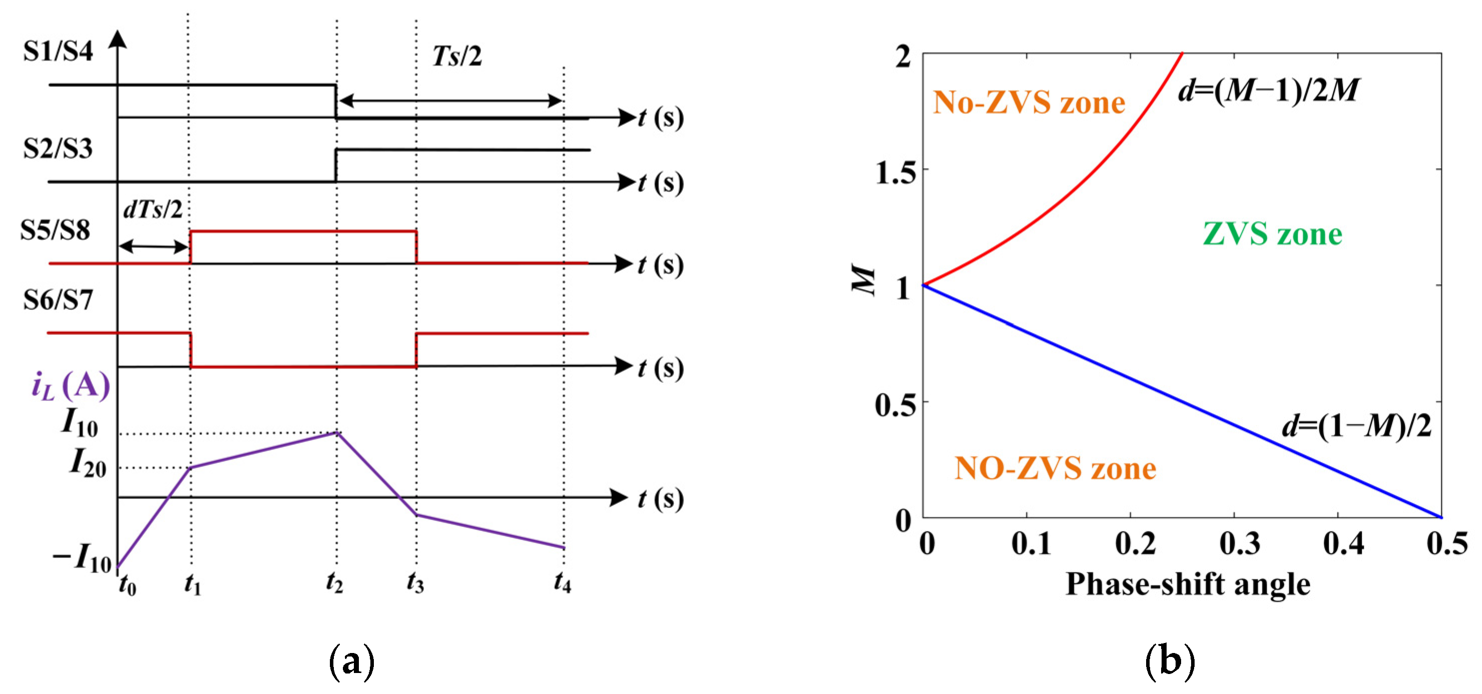
For fast charging scenarios, conventional bidirectional chargers commonly adopt a dual-stage configuration involving DC–DC and DC–AC, as depicted in Figure 2. According to the specific mode of either V2G or G2V, the DC–DC converter operates in buck or boost mode, and the DC–AC converter operates in rectifier or inverter mode [21] This conventional configuration of the bidirectional charger can give good results for V2G and grid-to-vehicle (G2V), but at the same time it can only serve a single entity (either the EV or power grid). This is due to the capacitance acting as the DC bus in the conventional charger; the current of capacitance I3 can be expressed by Equation (1). When the converter operates in steady-state, the capacitor voltage remains stable, and I3 is approximated to zero. At this stage, I1 is equal to I2, with their magnitudes and directions remaining the same, where I1 represents the current generated by the EV through the DC–DC converter, and I2 represents the current flowing towards the DC–AC converter. If the losses of DC–DC and DC–AC are ignored, the EV power is equal to the grid power, which can be formulated as PEV = Pg. This indicates that traditional chargers can only execute either EV instructions or grid instructions, without the ability to simultaneously accommodate both. Furthermore, in conventional chargers, it is necessary to have either a DC–DC converter or DC–AC converter to regulate the stability of the bus voltage. Due to the close correlation between the peak shaving and frequency regulation capabilities of the charger and the DC–AC converter, the stability of the bus voltage is typically controlled by the DC–DC converter. This means that the DC–DC converter lacks the additional freedom to control EV instructions. These analyses once again underscore the fact that the EV instructions and grid instructions in conventional chargers cannot be independently controlled; they can only be maintained as identical.
However, for a bidirectional grid-friendly charger with pulse heating and grid support functions, it is inevitable that conflicts in size and direction arise between the power grid command and the EV charge and discharge command, such as in pulse heating and grid instructions, or in valley-filling grid commands and EV charging instructions. The basic classification of instructions for grid and EV can be summarized into two categories as shown in Table 1, where x and y represent the size of the grid instruction and EV instruction, respectively. The sizes x and y may or may not be equal. In addition, the DC bus serves as a bridge for the two-stage converter, and the stability of its voltage is a prerequisite for the stable operation of the two-stage converter. However, during the transient period when the charging current changes in magnitude and direction (including pulse-current heating and variable-current charging), the capacitor voltage is unstable, which leads to high-frequency power fluctuations for the grid.
I 3 = C d U D C   b u s dt
From the above analysis, the capacitor (as DC bus) is the most susceptible to interference. Whether the grid side is vulnerable to shocks, or the grid command and EV command cannot be independently controlled, the underlying issue centers around the DC bus. Therefore, a new bidirectional charger topology is proposed, as shown in Figure 3, where DC–DC and DC–AC are dual active bridge (DAB) and T-type neutral point clamped (TNPC) inverters, respectively; the key differentiation lies in replacing a pair of DC bus capacitor with an identical pair of energy storage batteries. There are five reasons to support this replacement. Firstly, when the battery SOC is between 20% and 80%, the battery voltage can be approximated as a voltage source due to the small fluctuation [22], and the stability of the bus voltage can be freed from the control of the DC–DC link and the transient power fluctuation. In this situation, the DC–DC converter and the DC–AC converter have the capability to control the EV instructions and grid instructions separately. Unlike capacitors, energy storage batteries not only ensure voltage stability but also permit the flow of current. Consequently, the EV power and grid power can vary in magnitude and direction. Secondly, the energy storage battery is generally LiFePO4, which usually has a good high-rate discharge capacity, hence it can withstand the positive and negative switching of large currents. This is beneficial for pulse preheating and initial fast charging. Thirdly, as the charging power decreases during later fast charging stages, both the energy storage battery and EV can be replenished simultaneously, thereby guaranteeing a consistently adequate level of charge for the energy storage battery. Fourthly, for the new charger that utilizes energy storage batteries as the DC bus, although the price of energy storage batteries themselves is higher compared to capacitors, the new charger possesses a unique flexibility and grid-friendliness that traditional chargers cannot achieve. Hence, the new charger holds greater value. Additionally, since the voltage levels of the energy storage battery and EV battery are similar, decommissioned EV batteries can be used for cascade utilization, thereby reducing costs. Further cost analysis should also consider the impact of bus voltage fluctuations on other components, the pre-charging of bus capacitors, the definition of value assessment, and so on. Fifthly, the configuration of energy storage batteries itself is not very complex, and since the state estimation and intelligent management technologies for batteries are currently mature, direct migration can be performed.
Under this configuration, the SVPWM modulation of DC–AC also no longer uses the original fixed 700 V generation waveform but is based on the actual total battery voltage. The charging and discharging instructions of the EV (PEV) are guaranteed by controlling the I1 of DAB, the grid instructions (Pg) are accomplished through VSG in the TNPC, and the remaining power (Ps) is automatically made up by the energy storage batteries, so the vector equilibrium between the three can be satisfied as shown in Equation (2). In this way, the size and direction of PEV and Pg can be different at the same time, depending on the actual demand. In addition, when both PEV and Pg are in a steady state, a change in one instruction will not interfere with the other due to the stability of the bus voltage. As a result, during the execution of pulse preheating and variable-current fast charging, the pulse-current spikes can be absorbed by the energy storage battery to avoid the impact on the grid, and the high-power charging current of the EV can be jointly accommodated by the energy storage battery and power grid; the charging pile can therefore improve power utilization and reduce costs. Moreover, when the EV is not present, the peak and frequency modulation instructions of the grid can also be responded to by the energy storage battery. For example, the EVs are generally not charged at midday [23], but at this time photovoltaic is the moment of maximum production capacity, and the grid can transfer this excess energy to these distributed energy storage batteries.
P E V + P S = P g
Furthermore, the above analysis can be expanded to include a situation for a charging pile with two or more EVs; for this, the vector balance equation is transformed into Equation (3). A pile with dual guns is more common on the market today, and the vector balance (Equation (4)) at this stage is shown in Figure 3, where two EVs are connected in parallel to the DC bus through the same DAB. By controlling I 11 and I 12 , the two EVs can implement different instructions separately. This section next describes the control of the EVs and grid from two aspects: DAB and VSG.
I 1 = I 11 + I 12 + . . . +   I 1 n
P E V 1 +   P E V 2   +   P S = P g

2.2. DAB

DAB has become a popular topology for EVs in high-power situations due to its high efficiency, current isolation, inherent soft-switching capability, cascade scalability, wide voltage regulation capability, and other advantages [24]. Unlike other circuits employing resonant inductors and capacitors, the utilization of passive components is significantly reduced in DAB, thereby enhancing the density of the charging system [25]. Its structure is shown in the DC–DC section of Figure 3. Current isolation is achieved through transformers; L represents the sum of transformer leakage inductance and auxiliary inductance, and it is typically placed on the high-voltage side in order to reduce inductance current; n is the number of turns of the transformer. In order to simplify the circuit, analyze the principle, and design the DAB parameters, the conventional two-stage charger regards “TNPC and grid” as the equivalent impedance Req of DAB, as shown in Equation (5), where Ig represents the grid current. Since the new bidirectional charger still uses VSG to control the grid power, this idea can still be used.
R e q U D C   b u s I g I g = P g 380 3
The direction and magnitude of the DAB waveform are typically controlled using phase-shift controls, including single phase-shift (SPS), extended phase-shift (EPS), dual phase-shift (DPS), and triple phase-shift (TPS) [26]. Among these techniques, SPS uses only one phase shift variable between the primary and secondary bridges for ease of implementation and lower electromagnetic interference [27], so SPS control is preferred in this paper. Due to the lack of capacitor filtering, the output current generated by the DAB through the secondary bridge in the new bidirectional charger cannot be utilized directly as a control variable. Virtual capacitance filtering of I1 with a low-pass filter can solve this problem, and the expression of the low-pass filter is shown in Equation (6). As a result, the filter value of I1 is used as the control object of DAB, the quotient of PEV and UDC bus is used as reference current I1ref, and the difference between the two is realized by proportional–integral (PI) control for phase-shift control, as shown in Figure 3. Since the bidirectional power and phase shift angle under SPS control are monotonic and the corresponding phase shift angle adjustment range is [−0.5, +0.5], a limiting link can be added [28]. Bidirectional transmission of the DAB can be achieved by adding a bias of one period (Ts) to the phase-shift angle, so C = 2, as shown in Figure 3, where Ts = 1/fDC and fDC denotes the operating frequency of the DAB.
G L P F = 1 C v s + 1
The high frequency can increase the power density of the charger, but the switching loss will also increase. Therefore, it is necessary to analyze the zero-voltage switching (ZVS) range of DAB under the control of SPS to facilitate parameter design. If the dead time is ignored, the DAB timing diagram under SPS control is as shown in Figure 4a. To achieve parameter normalization, the voltage transfer ratio is defined as M = U Battery n U D C   b u s , with UBattery denoting the EV battery voltage and UDC bus representing the busbar voltage. The phase-shift angle between the bridges is denoted by the variable d, while T1 represents half of Ts. According to the operation principle of DAB, the inductor currents at three different time points t0, t1, and t2 are denoted as −I10, I20, and I10, respectively. The current difference ( i L 1 ,   i L 2 ) of inductor L between t0t1 and t1t2 is shown in Equations (7) and (8), and further the expressions of I10 and I20 can be obtained as shown in Equation (4); then, using M, we can simplify Equation (9) to obtain Equation (10).
i L 1 = I 10 + I 20 = 0 d T 1 U D C   b u s + U Battery / n L dt = U D C   b u s + U Battery / n d T 1 L
i L 2 = I 10 I 20 = d T 1 T 1 U D C   b u s U Battery / n L dt = U D C   b u s U Battery / n 1 d T 1 L
I 10 = T 1 2 L 2 U Battery n d + U D C   b u s U Battery n I 20 = T 1 2 L 2 U D C   b u s d U D C   b u s + U Battery n
I 10 = T 1 U D C   b u s 2 L 2 d M + 1 M I 20 = T 1 U D C   b u s 2 L 2 d 1 + M
In order to implement ZVS, it is necessary to satisfy I10 > 0 and I20 > 0 [29]; then, d   >   M 1 2 M and d   >   1 M 2 , as shown in Figure 4b. This observation reveals that when M = 1, DAB achieves ZVS throughout the full load range; when M ≠ 1, ZVS cannot be attained for DAB under light load conditions. Considering that the EV voltage typically ranges from 350 V to 450 V, this paper chooses an EV battery voltage of 400 V and busbar voltage of 700 V. In order to balance the design of the transformer volume, a turns ratio of n = 0.5 is selected. In this case, M = 8/7, which enables the realization of ZVS in the majority of load ranges.

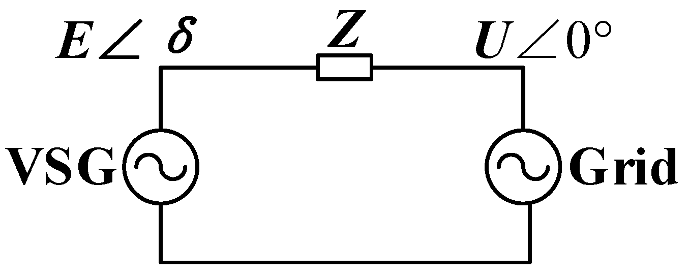
2.3. TNPC Based on VSG Control

TNPC adopts three-level technology, which can reduce the cost (by reducing the switching tube stress in high-power situations) and has lower conduction loss, which is very suitable for use in high-power EV scenarios [30]. VSG control can be divided into an outer ring and inner ring, among which the inner ring includes voltage and current rings. The overall control block diagram is shown in Figure 3.

2.3.1. VSG Outer Ring

The mechanical motion characteristics of the VSG are realized by simulating the second-order model of the synchronous generator, as shown in Equation (11) [31]. Here, J is the virtual rotational inertia; D is the damping coefficient; θ is the virtual internal potential phase angle; ω and ωn are the virtual angular frequency and rated angular frequency, respectively; and Pref and Pg indicate the reference value and actual value of active power, respectively.
d θ d t = ω J d ω d t P r e f ω n P g ω n D ω ω n
The control equation of reactive power and voltage is shown in Equation (12), where Em is the phase voltage amplitude of the potential within the VSG virtual; Kv denotes the QV droop coefficient; Qref and Qg are the reference value and actual value of reactive power, respectively; Un and U represent the rated value and actual value of the grid phase voltage; and E0 represents the voltage reference value.
E m = K v s Q r e f Q g + E 0 + ( 2 U n 2 U )
The calculation of Pg and Qg is shown in Equation (13). In order to reduce the influence of pulse momentum in the instantaneous power output of VSG, Pg and Qg need to pass through a low-pass filter.
P g = U a I a + U b I b + U c I c Q g = 1 3 ( U b c I a + U c a I b + U a b I c )
The phase angle θ and amplitude Em of the virtual internal potential of the VSG can be obtained through Equations (11)–(13); then, the instantaneous value of the virtual internal potential can be obtained from Equation (14).
E a = E m s i n θ E b = E m s i n ( θ 120 ° ) E c = E m s i n ( θ + 120 ° )

2.3.2. VSG Inner Voltage Loop

Virtual inductance Lv is introduced into the voltage loop of VSG, so the output impedance between the inverter and the grid is improved, which contributes to the decoupling and parameterization design of active and reactive loops of the VSG, as well as the suppression of circulating currents arising from the parallel operation of multiple VSGs [32]. If there is no virtual inductance, the system becomes reliant on the circuit parameters themselves, resulting in oscillations and overshoots in the grid power. This poses challenges for the operation of a weak grid, particularly as the penetration rates of new energy sources and power electronics continue to rise. However, an excessively large virtual inductance can also lead to a prolonged steady-state response time for the system.

2.3.3. VSG Inner Current Loop

The current loop of VSG adopts quasi-proportional resonant (QPR) control. Although proportional resonant (PR) control achieves infinite gain at the resonant frequency and exhibits better performance in harmonic disturbance rejection, its gain at non-resonant frequencies is significantly reduced. However, in practical applications, the grid frequency is not entirely constant. QPR control retains the advantages of PR control while mitigating the effects of grid frequency deviation by increasing the bandwidth [33]. The transfer function of the QPR controller is represented by Equation (15). In this equation, Kp denotes the proportional coefficient; Kr represents the resonance coefficient; ω0 signifies the resonant frequency, which is set as ω0 = ωn in this case; and ωc denotes the bandwidth of the resonant component. Considering that grid frequency fluctuations typically do not exceed 1 Hz, ωc is chosen as 2π rad/s.
G P R = K p + 2 K r ω c s s 2 + 2 ω c s + ω 0 2

3. Small-Signal Modeling and Performance Analysis of VSG

3.1. Small-Signal Modeling

Figure 5 shows the equivalent circuit of the VSG connected to the grid, where Z is the VSG output impedance, as shown in Equation (16).
Z = r 1 + j ω ( L 1 x L v ) j ω ( L 1 + L v ) = j X
The fundamental voltage vector at the middle point of the bridge arm of the inverter is set as Emδ, and the voltage vector at the point of common coupling (PCC) of the VSG is U∠ 0°, where δ is the phase difference between two voltage vectors, for which the expression is shown in Equation (17); ωg is the grid angular frequency. Then, the active and reactive power expressions of the inverter fed into the grid can be obtained as shown in Equation (18).
δ = ( ω ω g ) dt
P g = 3 U E m X sin δ Q g = 3 U E m X cos δ 3 U 2 X
When the EV is charging normally and the distribution grid is operating steadily, the voltage and frequency of the grid are both at their rated values. In such cases, there is no need for the EV to supply additional power to the grid. Therefore, the values of (δ0, Em0) are set as (0°, 220 V). To establish the small-signal model, the time-domain equations are subjected to perturbation separation and linearization; then, the Laplace transform equation for the small-signal model can be derived, as shown in Equation (19).
s δ ^ ( s ) = ω ^ ( s ) ω g ^ ( s ) ( J s + D ) ω ^ ( s ) = P g ^ ( s ) / ω n P g ^ ( s ) = 3 U n 2 X δ ^ ( s ) E m ^ ( s ) = K v s Q g ^ ( s ) U ^ ( s ) Q g ^ ( s ) = 3 U n X U ^ ( s ) + 3 U n X E m ^ ( s )
From Equation (19), the dynamic small-signal model of the mechanical equations of the VSG in the S-domain is obtained as shown in Figure 6. In order to simplify the expression, the variable G is introduced as depicted in Equation (20); this leads to the transfer function of active power, as shown in Equation (21).
G = 3 U n 2 X
P g P r e f = G J ω n s 2 + D J s + G J ω n

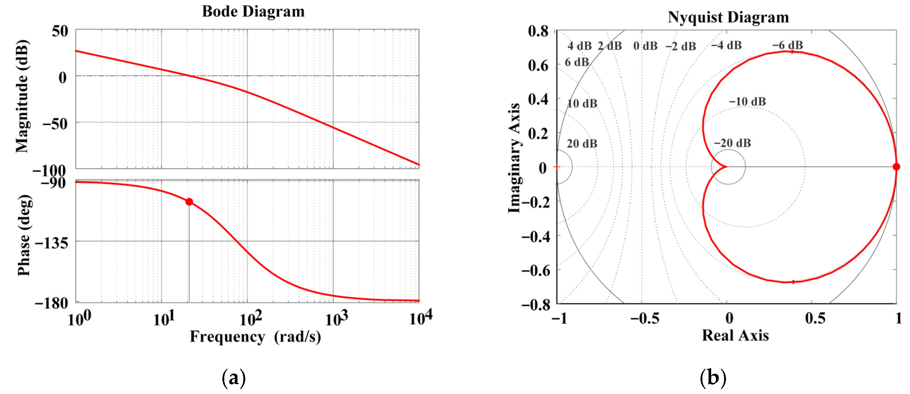
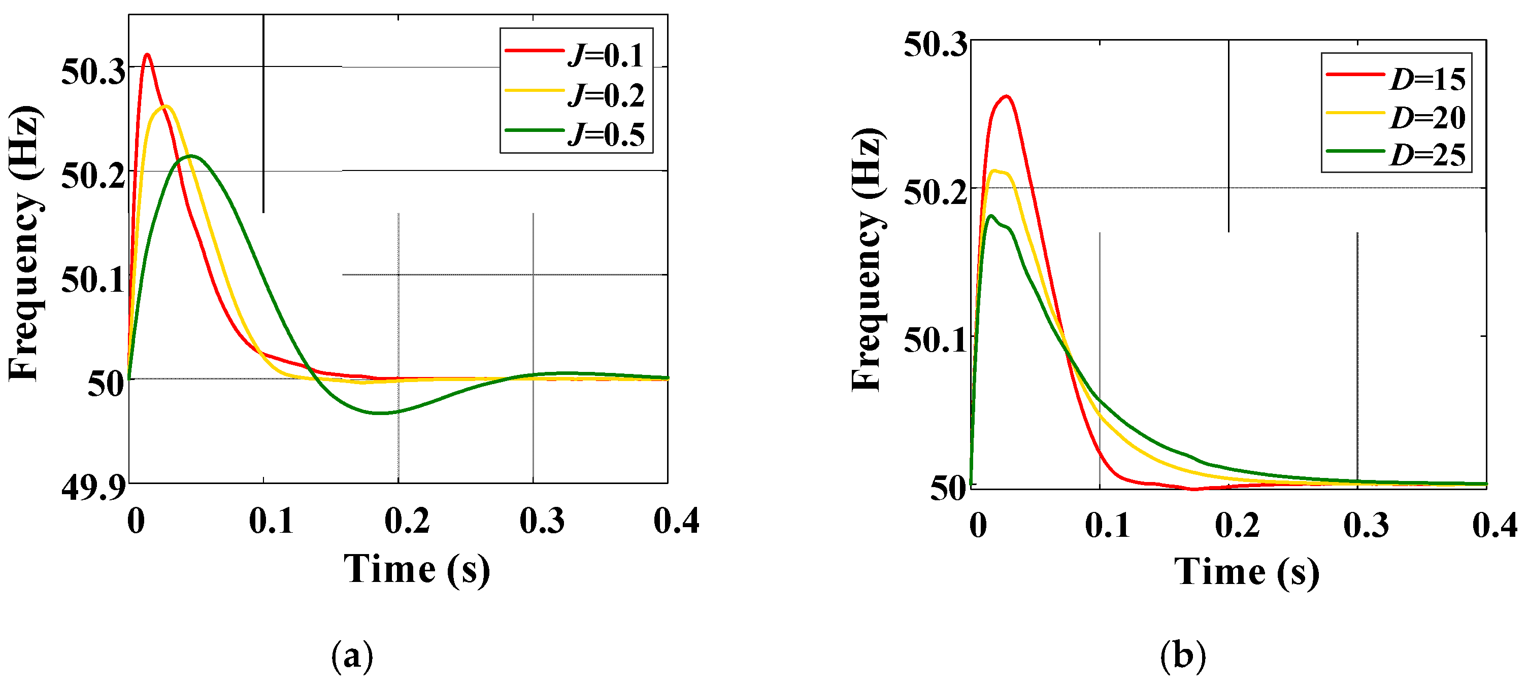
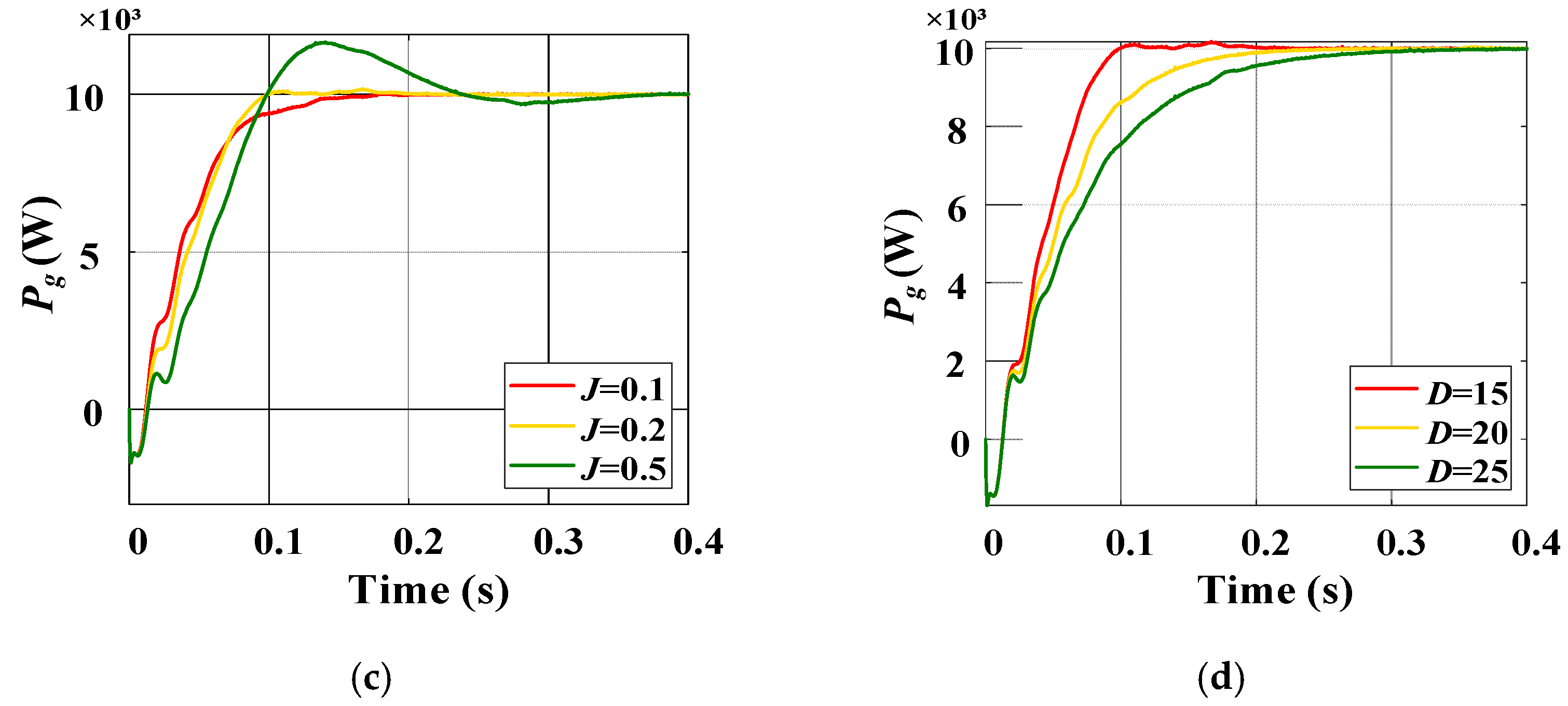
3.2. Dynamic Performance Analysis and Control Optimization

Equation (21) is a typical second-order transfer function whose natural oscillation angular frequency ω and damping coefficient ξ are shown in Equations (22) and (23). In order to maintain a steady state and faster regulation, when the transfer function is underdamped ( 0 < ξ < 1 ), the overshoot σ% and the regulation time ts are obtained as shown in Equations (24) and (25). Therefore, when D is fixed, a larger value of J results in a greater overshoot and a longer settling time. Conversely, when J is held constant, a larger value of D leads to a smaller overshoot and a shorter settling time. In engineering practice, for a typical underdamped second-order system, the parameter design usually involves selecting a damping coefficient ξ between 0.707 and 1. Taking these factors into consideration, the initial parameters of this paper were chosen as J = 0.2 and D = 15. The corresponding Bode plot and Nyquist plot of the active loop are shown in Figure 7. In the Bode plot, the magnitude margin is 94.5° and the phase margin is 74.4°; both the magnitude and phase margin are greater than zero, indicating stability. In the Nyquist plot, the origin is not enclosed, implying that the number of closed-loop poles in the right-hand half plane of the S-domain is zero, thus confirming system stability. The comparison between the theoretical and simulated values of the active power is shown in Figure 8. The two values exhibit only slight discrepancies during the transient period, while remaining consistent at other times. This demonstrates the correctness and reliability of the small-signal modeling and parameter selection.
ω = G J ω n
ξ = D ω n 4 J G
σ % = e π ξ / 1 π ξ 2
t s = 3.5 ξ ω n = 7 J D
The relationship between the virtual inertia J and damping coefficient D with respect to frequency can be derived from Equation (11), as shown in Equation (26) (apart from their impact on the output power). When P r e f / ω n P g / ω n J d ω / dt is fixed, a larger value of D results in a smaller frequency deviation ∆ω. Moreover, a higher value of J leads to a reduced rate of change in angular velocity. As a result, we can maintain the frequency stability by adjusting the size of J and D. The simulation results are shown in Figure 9 in accordance with the derivation. It can be observed that as J increases, the fluctuation range of frequency becomes smaller. However, the overshoot of active power increases, and the system takes longer to reach a steady state. On the other hand, as D increases, the fluctuation range of frequency also decreases, and the overshoot of active power decreases as well. However, the system’s settling time becomes longer.
ω = P r e f / ω n P g / ω n J d ω / d t D d ω dt = P r e f / ω n P g / ω n D ω J
By comparing the effects of J and D on the output power and frequency, we find that it is difficult to balance the speed and stability of the system with fixed parameters [34]. To enhance the control performance of the VSG, the adaptation of VSG parameters can be achieved by considering the characteristics of different stages within the system. The oscillation process of the system can be divided into four stages, as depicted in Figure 10: (1) t1t2, (2) t2t3, (3) t3t4, and (4) t4t5. In stage (1), the virtual rotor angular velocity of VSG is greater than the grid angular velocity (ω > ωn), and the rate of change of the angular velocity is positive ( d ω d t > 0); in stage (3), ω < ωn and d ω dt < 0. The difference (|ω − ωn|) between the two angular velocities gradually increases, indicating an acceleration phase in the rotor frequency. To suppress the rapid increase of ω, it is necessary to increase J. However, increasing J leads to an increase in σ% and ts. Consequently, D needs to be correspondingly increased to suppress the growth of σ% and ts. These two phases belong to the acceleration phase of the rotor angular frequency, because |ω − ωn| becomes gradually larger and increasing J suppresses the rapid increase in ω but also increases σ% and ts; hence, D is also increased to suppress σ% and ts. Conversely, ω > ωn but d ω dt < 0 in stage (2) and ω < ωn but d ω dt > 0 in stage (4); here, |ω − ωn| is gradually becoming smaller, which marks these as the deceleration stages of rotor angle frequency. Reducing J can accelerate | d ω dt |, facilitating a faster restoration of ω to ωn. Simultaneously, an appropriate increase in D can result in smaller values of σ% and ts. In summary, we can determine whether the rotor is in the acceleration or deceleration stage based on the positive or negative ∆ω ( d ω dt ) and then adjust J and D to enhance the stability and rapidity of the system.
Based on this foundation, the adaptive VSG depicted in Equations (27) and (28) is employed in this study. Here, J0 and D0 denote the initial values of J and D, respectively. Kj and KD represent the adaptive adjustment coefficients for J and D, respectively. The threshold value Tj and Td is utilized to prevent frequent variations in the value of J and D, caused by small-range fluctuations in frequency [35].
J = J 0 Δ ω ( d ω / d t ) 0 | ( d ω / d t ) | T j J 0 + K j | d ω dt | Δ ω ( d ω / d t ) > 0 | ( d ω / d t ) | > T j
D = D 0 Δ ω ( d ω / d t ) 0 | ( d ω / d t ) | T d D 0 + K d | Δ ω | Δ ω ( d ω / d t ) < 0 | ( d ω / d t ) | > T d

4. Working Condition Verification

In order to validate that the novel bidirectional charger does not cause disturbances to the grid during pulse-current heating and variable-current charging, four typical operating conditions are selected based on the characteristics of fast charging. These conditions correspond to the low-temperature pulse preheating stage, initial stage of fast charging, later stage of fast charging, and a charging pile with dual guns. To facilitate subsequent prototype validation, the power of the charger is scaled down to 10 kW based on actual scenarios, while the system parameters and specifications can be found in Table 2.

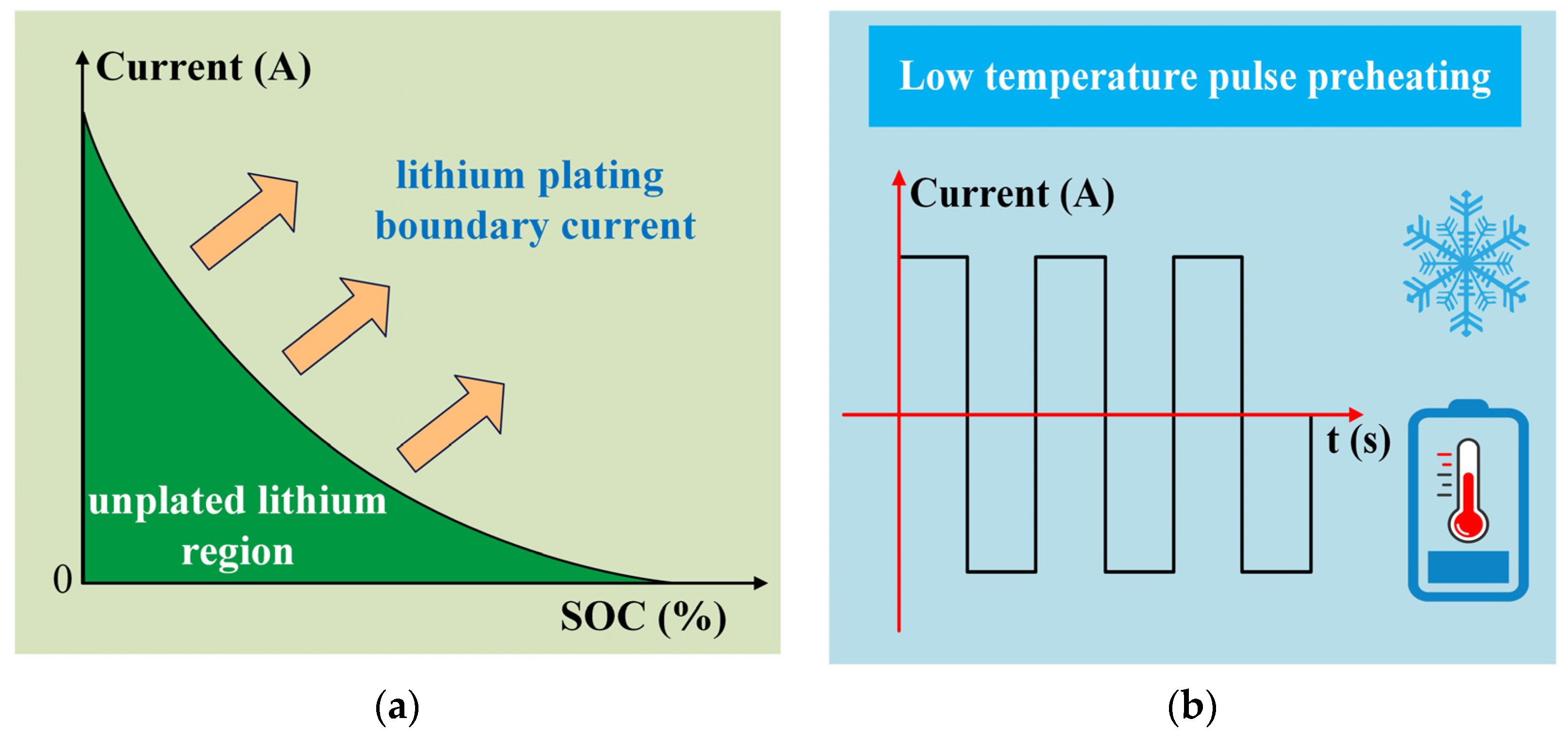
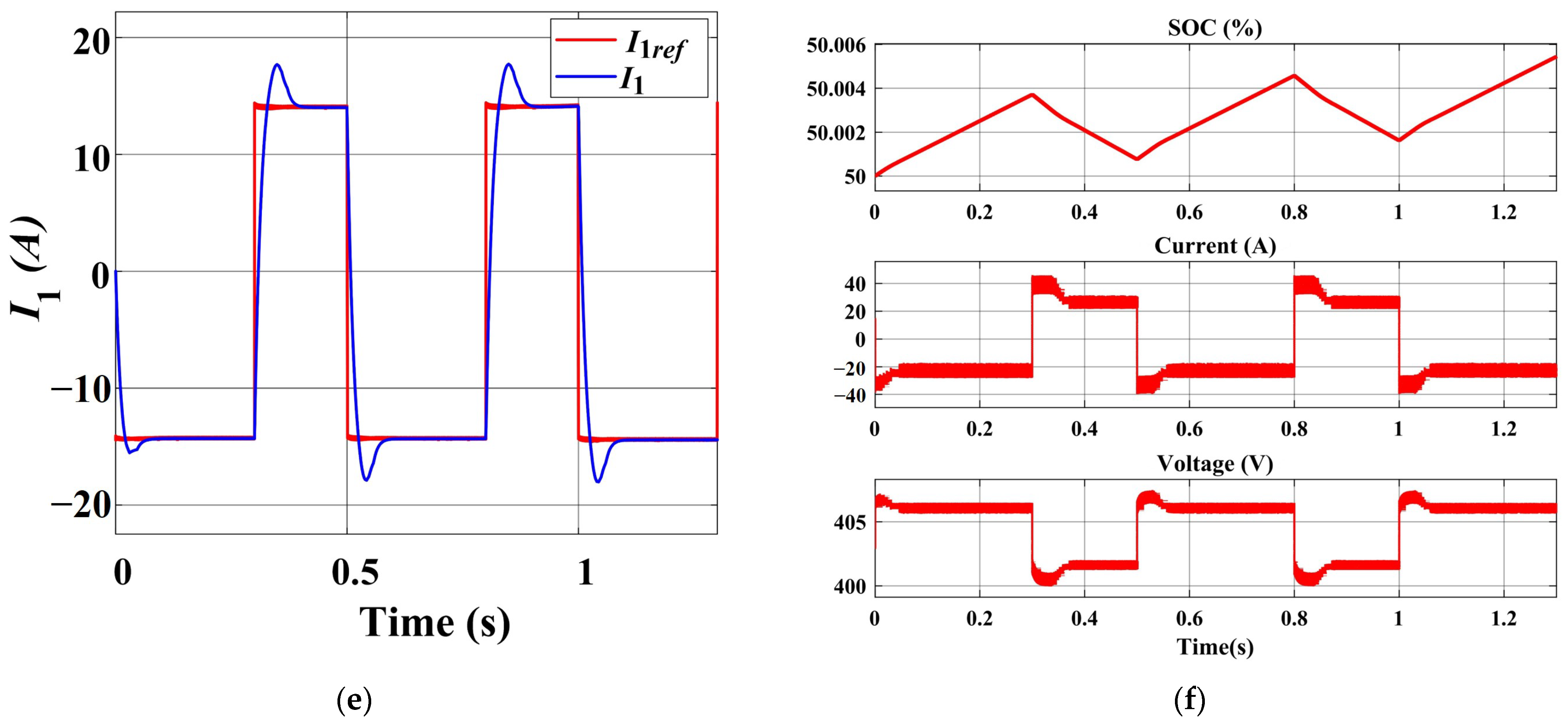
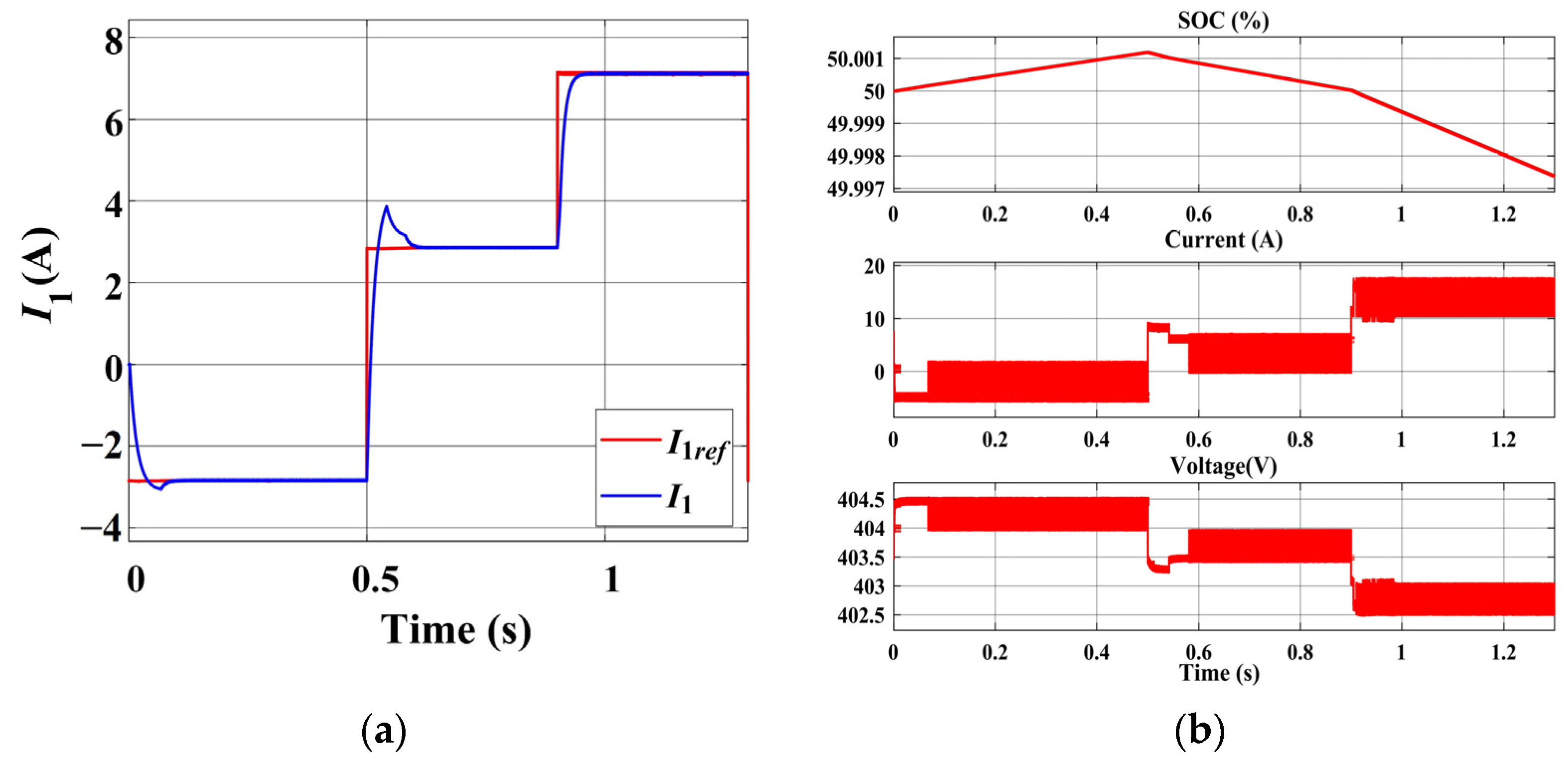
4.1. Low-Temperature Pulse Preheating Stage

The EV uses a pulse current for low-temperature preheating or pulse charging, where the pulse power is set to 10 kW and the positive and negative pulse durations are set to 0.3 s and 0.2 s, respectively. Because the winter morning electricity load is also very tight, the active power of the grid changes from the normal discharge of 5 kW to 3 kW at 0.5 s, and changes to 5 kW absorbed electric energy at 0.9 s. The reactive power of the grid is zero during the normal charging period, and the positive and negative instructions switch between 0.5 s and 0.9 s. Grid active and reactive power transformations in magnitude and direction are used to simulate the grid’s peak-frequency regulation commands. The variation in magnitude and direction of the active and reactive power of the grid is used to simulate the grid’s peak-frequency regulation commands. The simulation results demonstrate the continual preservation of vector balance among EVs, the grid, and the energy storage battery throughout the pulse preheating process. Both the EVs and the grid can independently execute distinct instructions to cater to their specific demands, without causing interference to one another. The pulse preheating process reaches a stable state within 0.1 s, ensuring that no power fluctuations occur within the grid, as shown in Figure 11 and Figure 12.
In Figure 11a, when the EV undergoes low-temperature pulse preheating according to the green reference command, both the grid and energy storage system contribute energy to the EV. The high power and repeated switching of the pulses do not impact the grid. When the pulse power and grid power differ in magnitude or direction, stable operation can be maintained. The low stress on the charging pile can enhance power utilization and reduce costs. The low-temperature preheating phase often occurs in the morning or evening, and the residential electricity demand tends to increase due to the use of electrical heating devices under these conditions. During this period, the grid can provide low-power charging to the EV (0.5–0.9 s), or it can also absorb energy from the energy storage system (0.9–1.3 s). Reactive power can be switched positively or negatively, indicating that the charger can also respond to grid peak commands. The adjustment time of Pg is ≤0.2 s and that of Qg is ≤0.15 s. In Figure 11b, due to the vector balance of the EVs, energy storage, and grid, when the power vector difference between EV and grid is larger, the SOC of energy storage changes faster. Figure 11c,d reflect the fact that the frequency and the dynamic harmonic waveform variations are not affected by the EV power variations, which are only related to the grid command. Compared with normal VSG control, adaptive VSG can better suppress the frequency change; when the grid power changes from −3 kW to 5 kW, the frequency fluctuations decrease by 0.05 Hz. Furthermore, the larger the difference between the dispatch instruction and the existing power, the more pronounced the suppression effect on frequency fluctuations, which is consistent with the theoretical analysis. During steady-state operation, the harmonic is satisfied, with a level below 5%. Figure 11e,f show the attainment of a steady state for the EV control variable I1 within 0.1 s. The voltage of the DC bus, which remains unaffected by changes in the EV pulse command and grid command, exhibits minimal fluctuations. As a result, the pulse frequency remains stable, and the regulation time at the battery terminal is further reduced.
Figure 12 demonstrates the ZVS of DAB bidirectional operations under the low-temperature pulse preheating stage. At 40 kHz, the switching tube of DAB uses MOSFET. When the EV is in a discharge state, the high-voltage MOSFET achieves soft shutdown, as shown in Figure 12a, and the low-voltage MOSFET achieves soft start, as shown in Figure 12c; when the EV is in the charging state, the high-voltage MOSFET realizes soft start, as shown in Figure 12b, and the low-voltage MOSFET realizes soft shutdown, as shown in Figure 12d; the soft-switching result proves the correctness of the theoretical analysis.
In order to better reflect the advantages of the new charger, we also simulated the pulse condition of the traditional charger, where the DC bus adopts a conventional capacitor bank and other parameters remain consistent. According to the previous analysis, when the traditional charger is in a steady state, the power of the EV is always equal in magnitude and direction to the power from the grid. Therefore, when the EV undergoes a 10 kW pulse, the power from the grid is also 10 kW, and its direction follows the EV’s oscillation. The grid power of the new charger can be scheduled according to its own requirements, without the need to be consistent with the power of the EV. If the pulse is set to switch direction every 0.4 s when simulating voltage regulation from the grid (by scheduling reactive power from 0 to −1 kW and 1 kW), the power variation from the grid is as shown in Figure 13a. It can be observed that the grid reaches a new steady state every 0.2 s. Since the VSG model already considers the decoupling of active and reactive power, the scheduling of reactive power does not affect the adjustment speed of active power. This implies that the pulse preheating of the EV can only switch every 0.2 s in the traditional charger, making the adjustment time twice as long as that of the new charger. Grid current quality, grid frequency, and harmonics are also affected, as shown in the Figure 13b. The adjustment time (0.2 s) aligns with that of the novel charger due to the implementation of adaptive VSG control with identical parameters. During the pulse preheating stage, the new charger eliminates grid power fluctuations, as opposed to traditional chargers that exhibit fluctuations for each pulse lasting 0.2 s or other predetermined duration. The utilization of traditional chargers for pulse preheating for a substantial number of EVs would consequently amplify the aggregated fluctuations exerted on the grid. Due to the independent control of pulse current and grid power in the new charger, the adjustment of the inductance in the new charger can be directly performed based on the existing state. This results in a significant overshoot (about 66.7%) in the DAB inductance in the new charger, as illustrated in Figure 13c. Conversely, in the traditional charger, the current in the inductance needs to return to zero before initiating pulse adjustment in the opposite direction, as shown in Figure 13d. The maximum current (26 A) of the traditional charger is 14 A smaller than that of the new charger (40 A), this is an area in which new chargers need to continue to be optimized. The voltage of the capacitor, acting as the DC bus, undergoes abrupt changes, which will pose a threat and challenge to the voltage of the TNPC switching tube, as shown by the blue line in Figure 13e. Compared to the traditional charger, the pulse preheating of the new charger will not cause high-frequency power fluctuations on the power grid. Additionally, as the energy storage battery acts as the DC bus (as shown by the yellow line in Figure 13e), the UDC bus does not produce voltage jumps resulting from the power scheduling of both the grid and EV, which can enhance the safety of the charger.

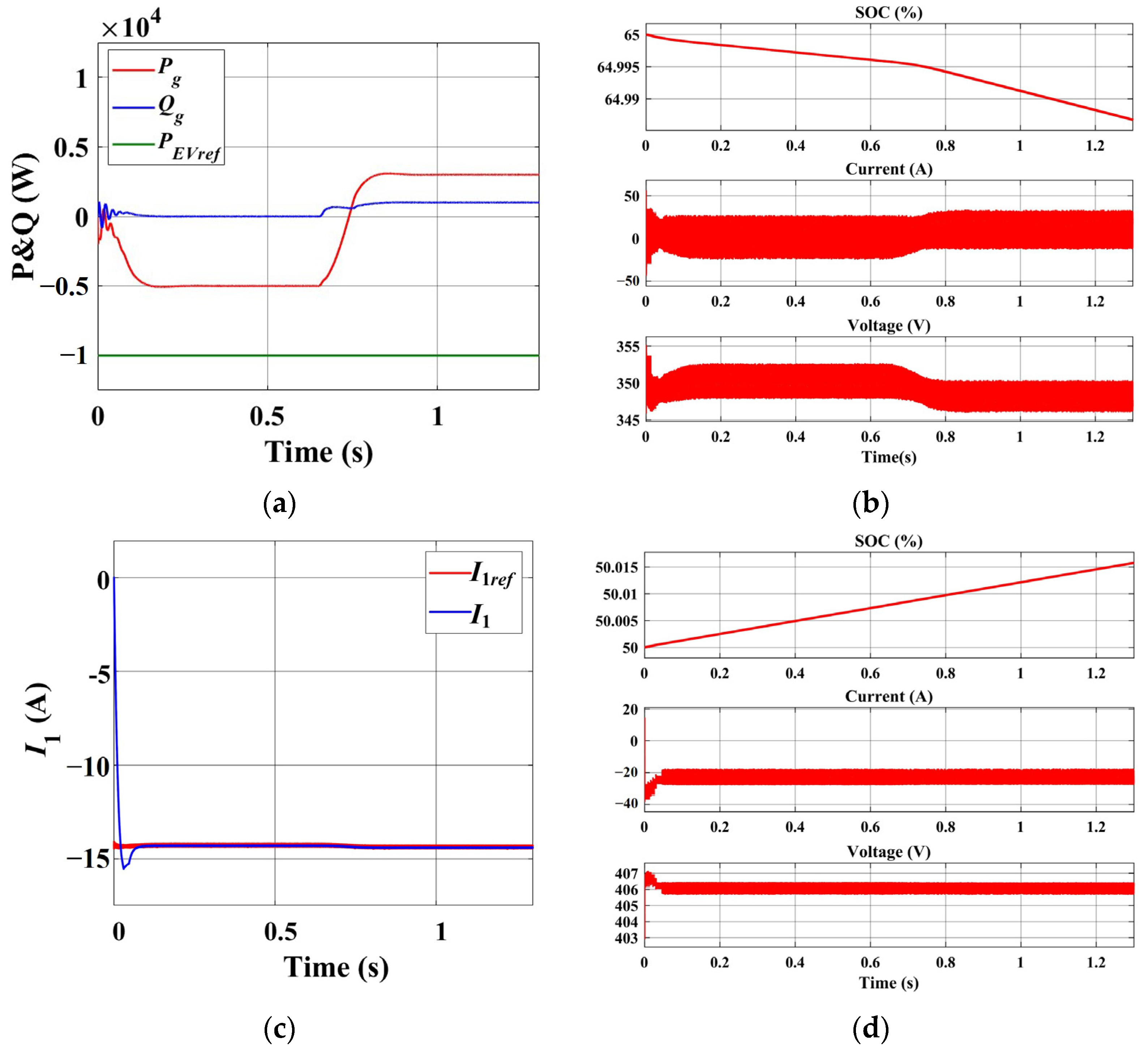
4.2. The Initial Fast Charge Stage

In the initial stage of fast charging, high-power charging rapidly replenishes energy, which can be regarded as a special scenario of pulse charging. If there are no price incentives, the charging of EV fleets tends to be highly concentrated; thus, high-rate charging during the same time period often imposes immense pressure on the grid. However, during the initial stage of fast charging in the new charger, both the grid and energy storage contribute to charging the EV. When the EV is charging at 10 kW, both the grid and the energy storage battery can provide 50% of the energy individually (i.e., 5 kW). The grid power can also be adjusted according to the actual situation, to change the proportion of EV charging power. If the grid load pressure is too high, the grid itself can obtain energy from the energy storage battery while the EV charges normally, as shown in Figure 14a,b. This scheduling ensures flexibility without affecting the execution of other instructions, as depicted in Figure 14c,d, where the control variable I1 and the EV battery current remain stable without being influenced by the grid power scheduling.

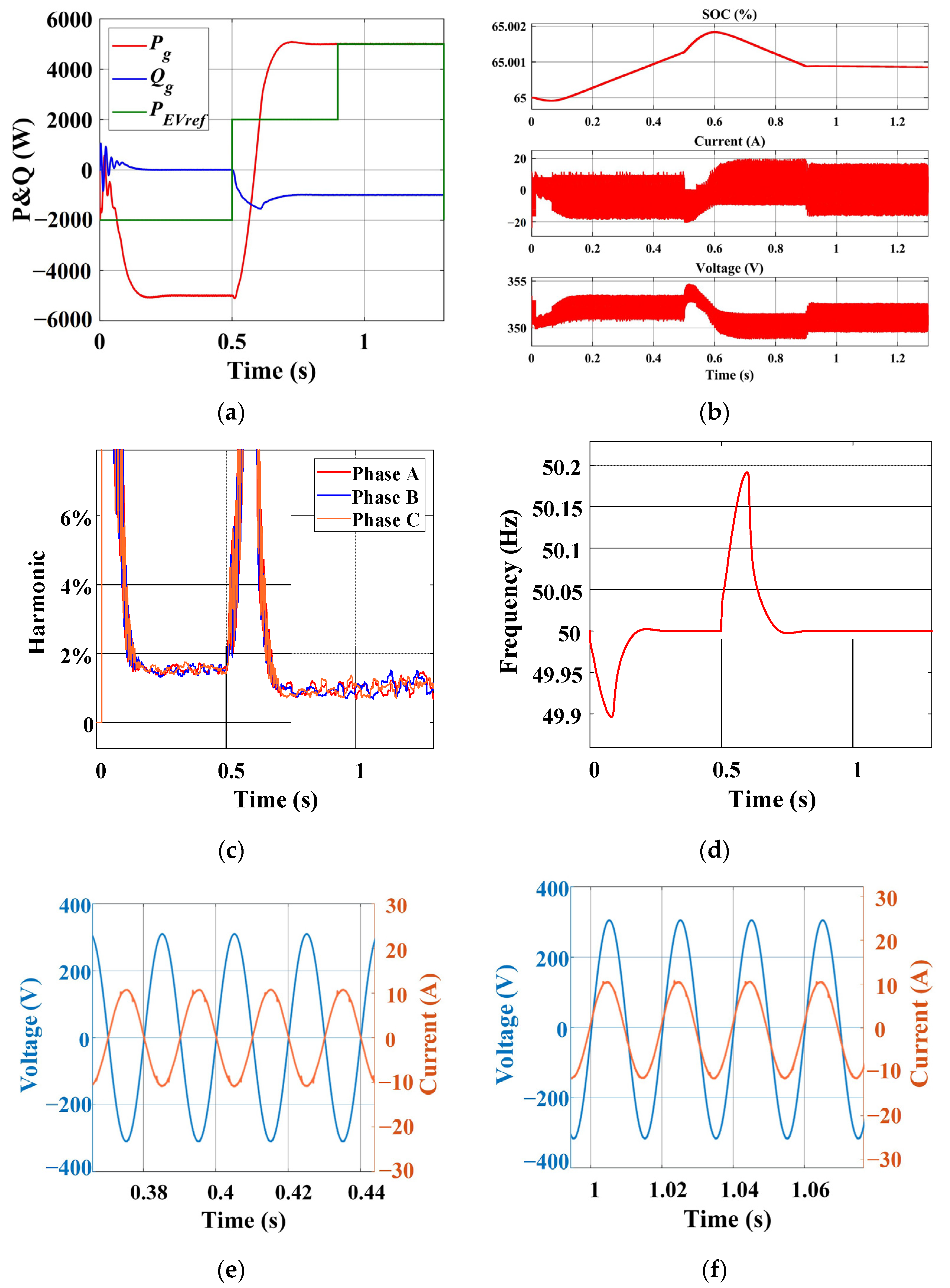
4.3. The Later Fast Charge Stage

In the later stage of fast charging for EVs, the charging power is reduced (set to 2 kW), and since the energy storage consumes a lot of energy during the early stage of fast charging, the grid (5 kW) simultaneously supplies power to both the EV (2 kW) and the energy storage system. In this way, by considering the characteristics of different stages of the fast charge curve, the energy storage battery as DC bus can receive timely energy supply. Furthermore, as the EV has already been charged to a substantial level, it can cooperate with the energy storage system to respond to grid dispatch (0.5–0.9 s). Alternatively, it can discharge (5 kW) back to the grid (5 kW) to fulfill grid dispatch requirements (0.9–1.3 s). The simulation results are shown in Figure 15.
Grid dispatch aligns with theoretical analysis and remains unaffected by EV commands, as depicted in Figure 15a,c,d. During the initial 0.5 s, the SOC rises because the energy storage is charged by the grid. Subsequently, from 0.5 s to 0.9 s, both the energy storage system and the EV respond to grid dispatch together, resulting in a decrease in SOC during the steady-state period; in the interval of 0.9 s to 1.3 s, the EV independently responds to grid dispatch, while the SOC of the energy storage system remains unchanged, as shown in Figure 15b. When the grid command is in the steady state, the bidirectional grid-connected voltage and current quality are excellent, as shown in Figure 15e,f. From 0 s to 0.5 s, the grid discharges with a zero reactive power command. As P ∝ sin δ and Q ∝ cos δ, the phase difference between the voltage and current is 180°. From 0.5 s to 1.3 s, the grid is charging and the phase difference between voltage and current should ideally be 0°. Nevertheless, due to the grid’s engagement in peak shaving and the reactive power command of −1000 W, there exists a slight deviation from the ideal 0° phase difference. The EV can seamlessly transition between three instructions: charging, auxiliary power supply, and independent power supply, as illustrated in Figure 16.

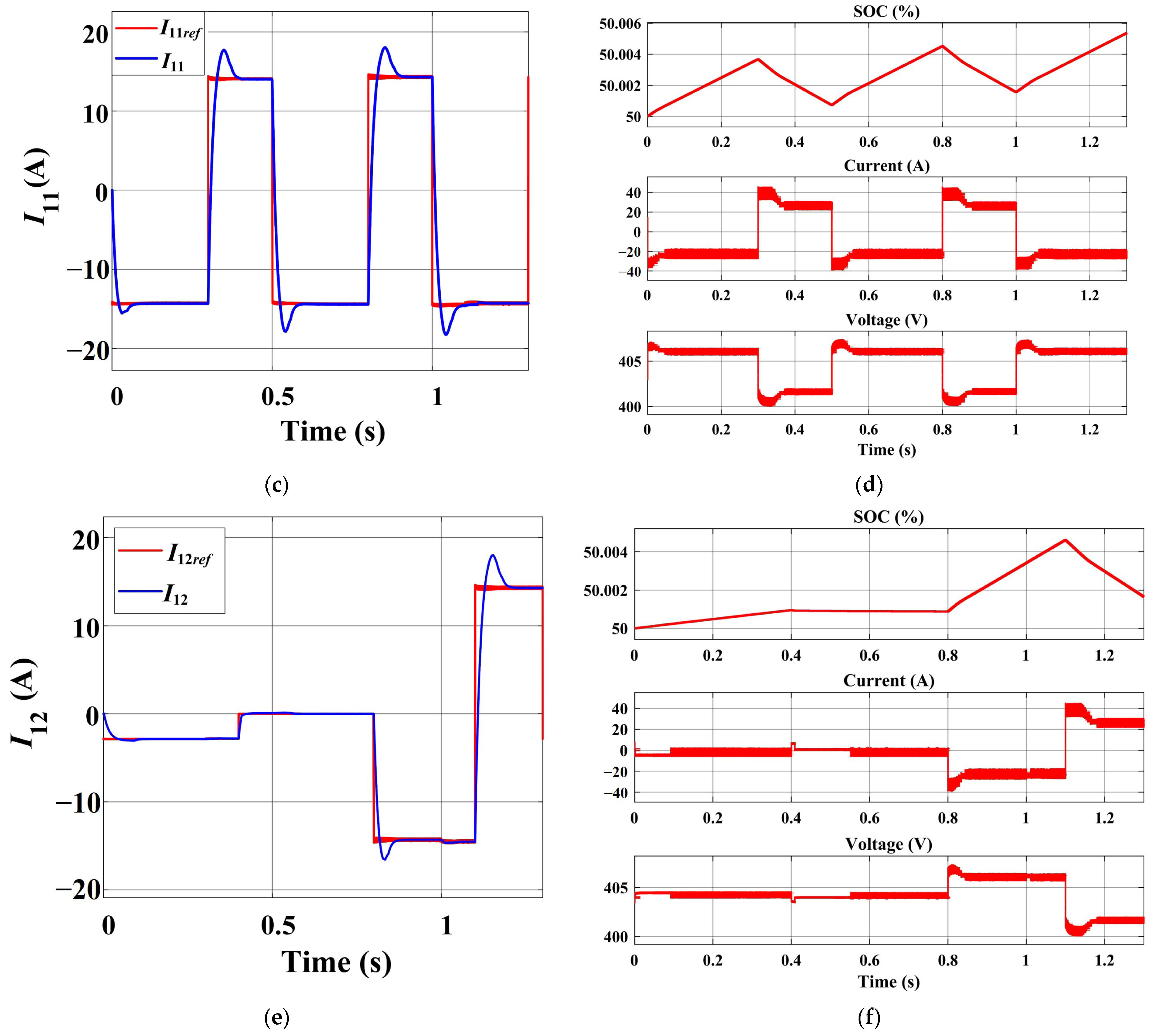
4.4. A Charging Pile with Dual Guns

The current mainstream charger in the market is equipped with two charging guns per charging pile. The novel topology proposed in this paper supports this configuration. Therefore, both EVs use the same DAB in parallel to access the DC bus, and the remaining circuitry and control components remain unchanged. We assume that EV1 consistently undergoes pulse heating, while EV2 transitions from fast charging to stop charging and then to pulse charging. This operating condition can simulate the impact on another EV and the grid when one EV disconnects or connects. The simulation results are illustrated in Figure 17.
When EVs are connected or disconnected in parallel, the grid dispatch instructions remain unaffected, as depicted by the red and blue curves in Figure 17a. The dashed black and green lines represent instruction variations for the two EVs. The vector balance between the energy storage, EVs, and grid is maintained, as shown in Figure 17b. Figure 17c,d shows the control variables and battery waveforms of EV1. The pulse instruction for EV1 reaches a steady state within 0.1 s, without being influenced by the grid instructions or the parallel connection of EVs. EV2 can be smoothly connected or disconnected, as shown in Figure 17e,f. Notably, during the period 0.4–0.8 s, the reference instruction is zero, but due to DAB circulation, there is still a weak current flow in the battery of EV2, and the SOC is basically unchanged.

5. Conclusions and Prospect

The paper proposes a novel bidirectional grid-friendly charger design for EVs that supports both low-temperature pulse preheating and variable-current fast charging while also providing V2G capabilities. The main innovation is replacing the traditional DC bus capacitors with an energy storage battery pack in a two-stage charger comprising DAB and TNPC. This allows the separate control of grid instructions and EV charging/discharging instructions, enabling pulse preheating and variable charging currents without causing fluctuations on the grid side. The control strategy incorporates SPS control and adaptive VSG control. Through analyses involving soft-switching and small-signal modeling, the key parameters of the DAB and control parameters of the VSG are designed. Subsequently, several representative operating conditions are validated, including low-temperature pulse preheating, power regulation and voltage regulation of the grid, and the distinctive characteristics of various stages of fast charging without lithium plating. Based on these results, several important conclusions are drawn.
(1)
Within the novel charger, the approximate voltage-source characteristics of the energy storage battery allow for the separate control of EV instructions and grid instructions. The pulse modulation time for EVs consistently achieves a steady state within 0.1 s. The new charger also exhibits a pulse modulation speed twice as fast as that of conventional chargers with identical parameters. Furthermore, the pulse-current heating and variable-current charging of EVs does not generate high-frequency power fluctuations on the grid, and the sequences of grid instructions do not have an impact on the speed of pulse modulation.
(2)
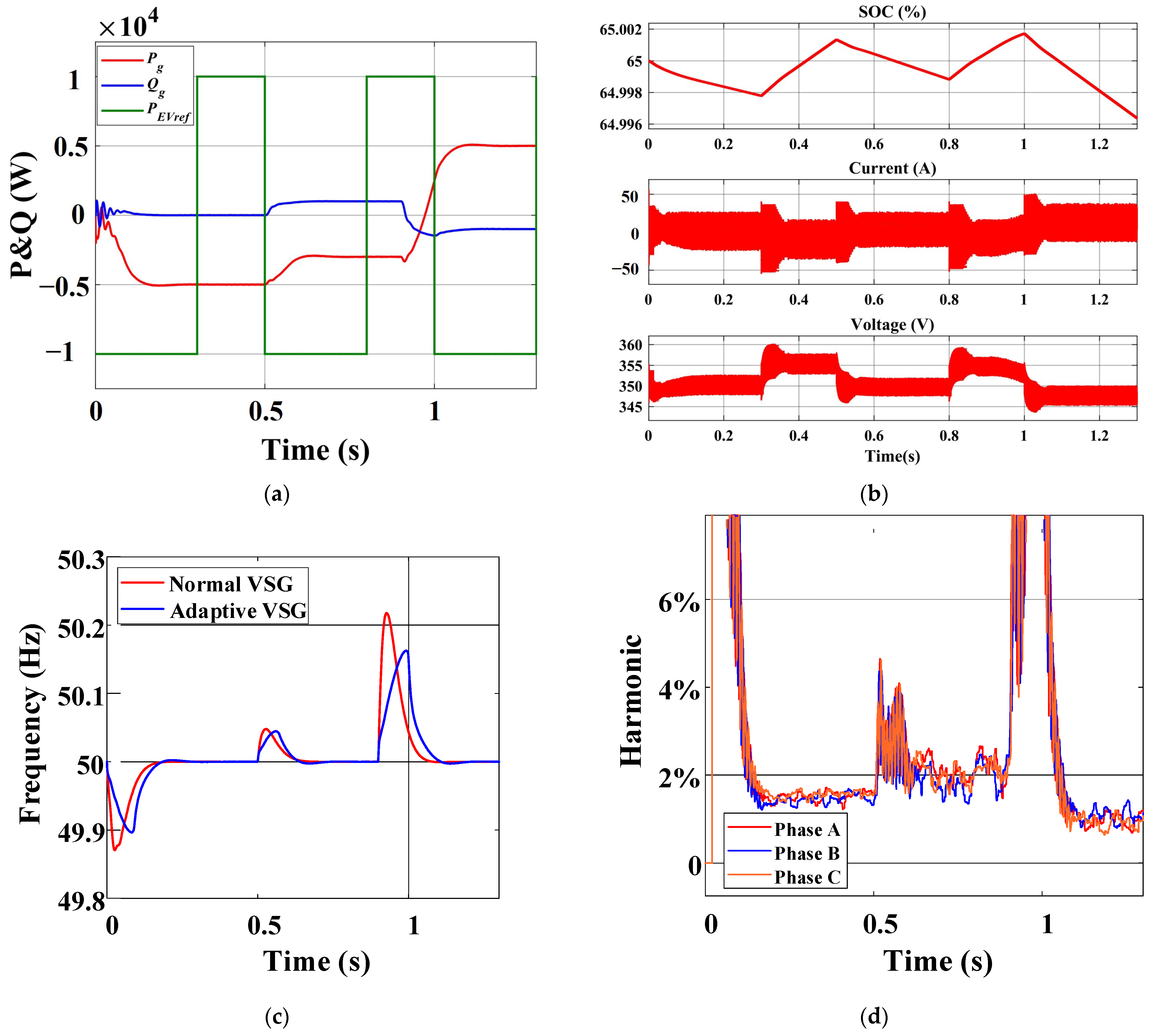
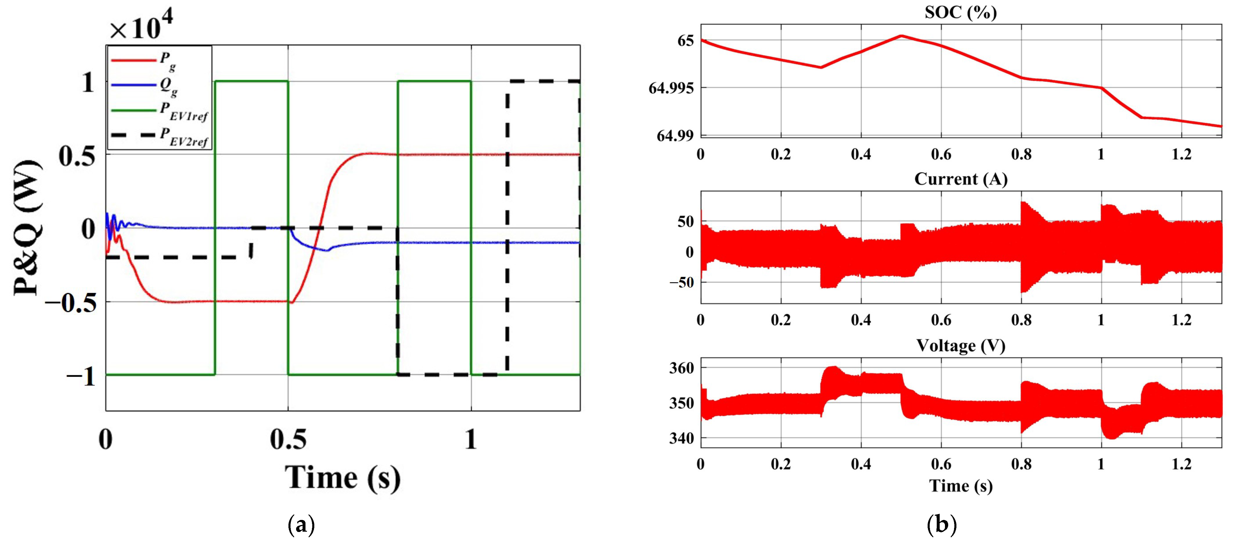
Compared to the traditional charger, the new charger exhibits enhanced flexibility and grid-friendliness. The power utilization of fast charging scenarios is improved. Furthermore, the power vector equilibrium is maintained between the EV, energy storage battery, and grid. Without impacting EV requirements, the grid can modify the proportion of supplied energy based on the actual scenario or obtain energy from either the EV or energy storage battery. The adaptive VSG not only supports the power regulation and voltage regulation of the grid but also provides inertia support. The active power can reach a new steady state within 0.2 s, while the reactive power can achieve steady state within 0.1 s.
(3)
In the absence of the EV, the energy storage battery can independently interact with the grid. Moreover, in a charging pile with dual guns, the instructions between EVs do not interfere with each other. The EV can smoothly connect or disconnect without causing any impact on the grid or the other EV.
This research can facilitate the promotion of EVs in cold regions and fast-charging conditions. It can also support the implementation of V2G technology in new power systems. In subsequent research, the key focus will be on establishing an experimental platform and conducting prototype validation, to thereby demonstrate the rationality and superiority of the architecture and control strategies proposed in this paper. Additionally, there are several aspects that warrant further investigation, to facilitate the industrialization of charger products. These include optimizing the phase-shift control of the DAB by considering the inductive peak current and efficiency. Researching the parallel operation of multiple chargers is also indispensable.

Author Contributions

Conceptualization, N.J., J.W. and Y.L.; validation, N.J., J.W. and L.H.; writing—original draft preparation, J.W.; writing—review and editing, N.J., Y.L. and L.H.; visualization, Y.L., J.W. and L.H.; supervision, X.W., H.W. and L.L. All authors have read and agreed to the published version of the manuscript.

Funding

This work was supported by the National Natural Science Foundation of China (grant no. 52207241), funded by the China National Postdoctoral Program for Innovative Talents (grant no. BX20220171), and supported by the Open Fund Project of State Key Laboratory of Automotive Safety and Energy (no. KFY2222). In addition, it was supported by the Tsinghua–Toyota Joint Research Fund.

Institutional Review Board Statement

Not applicable.

Informed Consent Statement

Not applicable.

Data Availability Statement

The data presented in this study are available in the article.

Conflicts of Interest

The authors declare no conflicts of interest.

References

  1. Li, Y.; Wei, Y.; Zhu, F.; Du, J.; Zhao, Z.; Ouyang, M. The path enabling storage of renewable energy toward carbon neutralization in China. eTransportation 2023, 16, 100226. [Google Scholar] [CrossRef]
  2. Aghajan-Eshkevari, S.; Azad, S.; Nazari-Heris, M.; Ameli, M.T.; Asadi, S. Charging and discharging of electric vehicles in power systems: An updated and detailed review of methods, control structures, objectives, and optimization methodologies. Sustainability 2022, 14, 2137. [Google Scholar] [CrossRef]
  3. Xu, W.; Wu, X.; Li, Y.; Wang, H.; Lu, L.; Ouyang, M. A comprehensive review of DC arc faults and their mechanisms, detection, early warning strategies, and protection in battery systems. Renew. Sustain. Energy Rev. 2023, 186, 113674. [Google Scholar] [CrossRef]
  4. Chen, X.; Tian, G.; Huang, Y.; Yang, Y.; Li, J.; Wu, Y.; Chi, Y. New power system development path mechanism design. Glob. Energy Interconnect. 2023, 6, 166–174. [Google Scholar] [CrossRef]
  5. Khan, I.A.; Mokhlis, H.; Mansor, N.N.; Illias, H.A.; Awalin, L.J.; Wang, L. New trends and future directions in load frequency control and flexible power system: A comprehensive review. Alex. Eng. J. 2023, 71, 263–308. [Google Scholar] [CrossRef]
  6. Zhou, T.; Huang, J.; Quan, H.; Xu, Y.; Liu, Z. Inertial security region estimation and analysis of new power systems considering renewable energy virtual inertial. Energy Rep. 2023, 9, 1836–1849. [Google Scholar] [CrossRef]
  7. Ravi, S.S.; Aziz, M. Utilization of electric vehicles for vehicle-to-grid services: Progress and perspectives. Energies 2022, 15, 589. [Google Scholar] [CrossRef]
  8. Elma, O.; Cali, U.; Kuzlu, M. An overview of bidirectional electric vehicles charging system as a Vehicle to Anything (V2X) under Cyber–Physical Power System (CPPS). Energy Rep. 2022, 8, 25–32. [Google Scholar] [CrossRef]
  9. Khan, W.; Ahmad, F.; Alam, M.S. Fast EV charging station integration with grid ensuring optimal and quality power exchange. Eng. Sci. Technol. Int. J. 2019, 22, 143–152. [Google Scholar] [CrossRef]
  10. Piao, N.; Gao, X.; Yang, H.; Guo, Z.; Hu, G.; Cheng, H.-M.; Li, F. Challenges and development of lithium-ion batteries for low temperature environments. Etransportation 2022, 11, 100145. [Google Scholar] [CrossRef]
  11. Ge, H. Alternating Current Preheating and Fast Charging of Lithium-Ion Batteries with Lithium Plating Prevention at Low Temperatures. Doctoral Dissertation, Tsinghua University, Beijing, China, 2017. [Google Scholar]
  12. Qin, Y.; Zuo, P.; Chen, X.; Yuan, W.; Huang, R.; Yang, X.; Du, J.; Lu, L.; Han, X.; Ouyang, M. An ultra-fast charging strategy for lithium-ion battery at low temperature without lithium plating. J. Energy Chem. 2022, 72, 442–452. [Google Scholar] [CrossRef]
  13. Hu, X.; Zheng, Y.; Howey, D.A.; Perez, H.; Foley, A.; Pecht, M. Battery warm-up methodologies at subzero temperatures for automotive applications: Recent advances and perspectives. Prog. Energy Combust. Sci. 2020, 77, 100806. [Google Scholar] [CrossRef]
  14. Qin, Y.; Xu, Z.; Xiao, S.; Gao, M.; Bai, J.; Liebig, D.; Lu, L.; Han, X.; Li, Y.; Du, J. Temperature consistency–oriented rapid heating strategy combining pulsed operation and external thermal management for lithium-ion batteries. Appl. Energy 2023, 335, 120659. [Google Scholar] [CrossRef]
  15. Mateen, S.; Amir, M.; Haque, A.; Bakhsh, F.I. Ultra-fast charging of electric vehicles: A review of power electronics converter, grid stability and optimal battery consideration in multi-energy systems. Sustain. Energy Grids Netw. 2023, 35, 101112. [Google Scholar] [CrossRef]
  16. Antoun, J.; Kabir, M.E.; Atallah, R.; Moussa, B.; Ghafouri, M.; Assi, C. Impact analysis of EV preconditioning on the residential distribution network. In Proceedings of the 2020 IEEE International Conference on Communications, Control, and Computing Technologies for Smart Grids (SmartGridComm), Virtual, 11–13 November 2020. [Google Scholar]
  17. Antoun, J.; Kabir, M.E.; Atallah, R.; Moussa, B.; Ghafouri, M.; Assi, C. Assisting residential distribution grids in overcoming large-scale EV preconditioning load. IEEE Syst. J. 2021, 16, 4345–4355. [Google Scholar] [CrossRef]
  18. Meng, X.; Liu, J.; Liu, Z. A generalized droop control for grid-supporting inverter based on comparison between traditional droop control and virtual synchronous generator control. IEEE Trans. Power Electron. 2018, 34, 5416–5438. [Google Scholar] [CrossRef]
  19. He, P.; Li, Z.; Jin, H.; Zhao, C.; Fan, J.; Wu, X. An adaptive VSG control strategy of battery energy storage system for power system frequency stability enhancement. Int. J. Electr. Power Energy Syst. 2023, 149, 109039. [Google Scholar] [CrossRef]
  20. Rathore, B.; Chakrabarti, S.; Srivastava, L. A Self-Regulated Virtual Impedance control of VSG in a microgrid. Electr. Power Syst. Res. 2021, 197, 107289. [Google Scholar] [CrossRef]
  21. Sharma, A.; Sharma, S. Review of power electronics in vehicle-to-grid systems. J. Energy Storage 2019, 21, 337–361. [Google Scholar] [CrossRef]
  22. Zhang, Z.; Lu, L.; Li, Y.; Wang, H.; Ouyang, M. Accurate Remaining Available Energy Estimation of LiFePO4 Battery in Dynamic Frequency Regulation for EVs with Thermal-Electric-Hysteresis Model. Energies 2023, 16, 5239. [Google Scholar] [CrossRef]
  23. Langbroek, J.H.; Franklin, J.P.; Susilo, Y.O. When do you charge your electric vehicle? A stated adaptation approach. Energy Policy 2017, 108, 565–573. [Google Scholar] [CrossRef]
  24. Mou, D.; Yuan, L.; Li, Y.; Wei, S.; Chen, J.; Zeng, Y.; Zhao, Z. Efficiency-oriented circuit parameter optimization of dual active bridge converter. eTransportation 2022, 14, 100208. [Google Scholar] [CrossRef]
  25. Yan, Y.; Bai, H.; Foote, A.; Wang, W. Securing full-power-range zero-voltage switching in both steady-state and transient operations for a dual-active-bridge-based bidirectional electric vehicle charger. IEEE Trans. Power Electron. 2019, 35, 7506–7519. [Google Scholar] [CrossRef]
  26. Bu, Q.; Wen, H.; Wen, J.; Hu, Y.; Du, Y. Transient DC bias elimination of dual-active-bridge DC–DC converter with improved triple-phase-shift control. IEEE Trans. Ind. Electron. 2019, 67, 8587–8598. [Google Scholar] [CrossRef]
  27. Yalçın, S.; Göksu, T.; Kesler, S.; Bingöl, O. Experimental analysis of phase shift modulation methods effects on EMI in dual active bridge DC-DC converter. Eng. Sci. Technol. Int. J. 2023, 43, 101435. [Google Scholar] [CrossRef]
  28. Zhao, B.; Song, Q.; Liu, W.; Sun, Y. Overview of dual-active-bridge isolated bidirectional DC–DC converter for high-frequency-link power-conversion system. IEEE Trans. Power Electron. 2013, 29, 4091–4106. [Google Scholar] [CrossRef]
  29. Rodríguez Alonso, A.; Vázquez Ardura, A.; González Lamar, D.; Hernando Álvarez, M.M.; Sebastián Zúñiga, F.J. Different purpose design strategies and techniques to improve the performance of a dual active bridge with phase-shift control. IEEE Trans. Power Electron. 2015, 30, 790–804. [Google Scholar] [CrossRef]
  30. Jin, H.; Wang, J.; Zhao, J. General average model of T-type three-level converter for active compensation circuit of distribution network. Energy Rep. 2021, 7, 493–501. [Google Scholar] [CrossRef]
  31. Zhong, Q.-C.; Nguyen, P.-L.; Ma, Z.; Sheng, W. Self-synchronized synchronverters: Inverters without a dedicated synchronization unit. IEEE Trans. Power Electron. 2013, 29, 617–630. [Google Scholar] [CrossRef]
  32. Wen, T.; Zhu, D.; Zou, X.; Jiang, B.; Peng, L.; Kang, Y. Power coupling mechanism analysis and improved decoupling control for virtual synchronous generator. IEEE Trans. Power Electron. 2020, 36, 3028–3041. [Google Scholar] [CrossRef]
  33. Eroğlu, H.; Cuce, E.; Cuce, P.M.; Gul, F.; Iskenderoğlu, A. Harmonic problems in renewable and sustainable energy systems: A comprehensive review. Sustain. Energy Technol. Assess. 2021, 48, 101566. [Google Scholar] [CrossRef]
  34. Tian, A.; Wu, Y.; Hu, Z.; Wang, Z.; Wu, T.; Jiang, J.; Peng, Z. Two-stage PV grid-connected control strategy based on adaptive virtual inertia and damping control for DC-link capacitor dynamics self-synchronization. J. Energy Storage 2023, 72, 108659. [Google Scholar] [CrossRef]
  35. Li, D.; Zhu, Q.; Lin, S.; Bian, X. A self-adaptive inertia and damping combination control of VSG to support frequency stability. IEEE Trans. Energy Convers. 2016, 32, 397–398. [Google Scholar] [CrossRef]
Figure 1. Typical working conditions of EV: (a) fast-charging Mas curve of lithium-ion batteries and (b) low-temperature pulse preheating.
Sustainability 16 00367 g001
Figure 2. Basic structure of V2G and G2V modes for fast-charging scenarios.
Sustainability 16 00367 g002
Figure 3. A novel bidirectional grid-friendly EV charger.
Sustainability 16 00367 g003
Figure 4. The timing diagram and ZVS range of DAB under SPS control: (a) timing diagram and (b) ZVS range.
Sustainability 16 00367 g004
Figure 5. VSG grid-connected equivalent circuit.
Sustainability 16 00367 g005
Figure 6. Small-signal model of active power of VSG.
Sustainability 16 00367 g006
Figure 7. Active loop: (a) Bode diagram and (b) Nyquist diagram.
Sustainability 16 00367 g007
Figure 8. The comparison between the theoretical and simulated values of the active power.
Sustainability 16 00367 g008
Figure 9. The effect of J and D on frequency: (a) the effect of J on frequency, (b) the effect of D on frequency, (c) the effect of J on output power, and (d) the effect of D on output power.
Sustainability 16 00367 g009aSustainability 16 00367 g009b
Figure 10. Power-angle and frequency oscillation curve of synchronous generator.
Sustainability 16 00367 g010
Figure 11. The relevant waveform of the charger in low-temperature pulse preheating stage: (a) the contrast between Pg and Qg and the PEVref, (b) energy storage battery, (c) the effect of normal VSG and adaptive VSG on frequency, (d) dynamic harmonic waveform, (e) the reference current and actual current of EV, and (f) EV battery.
Sustainability 16 00367 g011aSustainability 16 00367 g011b
Figure 12. The ZVS of DAB under low-temperature pulse preheating stage: (a) MOSFET on the high-voltage side in EV discharge mode, (b) MOSFET on the high-voltage side in EV charging mode, (c) MOSFET on the low-voltage side in EV discharge mode, and (d) MOSFET on the low-voltage side in EV charging mode.
Sustainability 16 00367 g012
Figure 13. The pulse condition of the traditional charger: (a) the power change of the grid, (b) dynamic harmonic waveform, (c) the inductive current of DAB for the new charger, (d) the inductive current of DAB for the traditional charger, and (e) the voltage of the DC bus.
Sustainability 16 00367 g013
Figure 14. The relevant waveform of charger with initial fast charge stage: (a) the contrast between Pg and Qg and the PEVref, (b) energy storage battery, (c) the reference current and the actual current of EV, and (d) EV battery.
Sustainability 16 00367 g014
Figure 15. Grid and energy storage waveforms in the later stage of fast charging: (a) the contrast between Pg and Qg and the PEVref, (b) energy storage battery, (c) dynamic harmonic waveform, (d) inverter grid-connection frequency, (e) the voltage and current of the inverter connected to the grid when grid discharges, and (f) the voltage and current of the inverter connected to the grid when grid charges.
Sustainability 16 00367 g015
Figure 16. The main waveform of EV in the later fast charge stage: (a) EV reference current and actual current with later fast charge stage and (b) EV battery.
Sustainability 16 00367 g016
Figure 17. The main waveform in one charging pile with dual guns: (a) the contrast between Pg, Qg, and PEV1ref and PEV2ref; (b) energy storage battery; (c) EV1 reference current and actual current; (d) EV1 battery; (e) EV2 reference current and actual current; and (f) EV2 battery.
Sustainability 16 00367 g017aSustainability 16 00367 g017b
Table 1. Basic classification of instructions for grid and EV.
Grid Instructions (Pg)EV Instructions (PEV)
Same direction+x+y
xy
Opposite direction+xy
x+y
Table 2. System parameters.
ParametersSymbolValue
EV battery voltageUBattery400 V
Transformer turns ration2
DAB inductanceL82 uH
Energy storage battery voltageE1, E2350 V
Filter inductanceL11 mH
Filter capacitanceC110 uF
Grid voltageUabc220 V
Grid frequencyfg50 Hz
Switch frequencyfDC40 kHz
fAC15 kHz
Virtual inertiaJ0.2
Virtual dampingD15
Virtual inductanceLv3.5 mH
Inertia adjustment coefficientsKj0.1
Damping adjustment coefficientsKd15
The threshold of JTj0.6
The threshold of DTd0.6
Disclaimer/Publisher’s Note: The statements, opinions and data contained in all publications are solely those of the individual author(s) and contributor(s) and not of MDPI and/or the editor(s). MDPI and/or the editor(s) disclaim responsibility for any injury to people or property resulting from any ideas, methods, instructions or products referred to in the content.

