Article

Microscopic Mechanism and Road Performance Analysis of MgO Carbonation–Solidification of Dredged Sediment

1
School of Transportation Engineering, Shandong Jianzhu University, Jinan 250101, China
2
School of Municipal & Environmental Engineering, Shandong Jianzhu University, Jinan 250101, China
3
College of Shipbuilding Engineering, Harbin Engineering University, Harbin 150001, China
4
School of Transportation and Logistics Engineering, Shandong Jiaotong University, Jinan 250357, China
*
Authors to whom correspondence should be addressed.
Sustainability 2024, 16(12), 5097; https://doi.org/10.3390/su16125097
Submission received: 25 April 2024 / Revised: 29 May 2024 / Accepted: 13 June 2024 / Published: 15 June 2024

Abstract

:
MgO carbonization is a green and low-carbon soil improvement technology. The use of MgO carbonization to solidify dredged sediment and transform it into road-building materials has significant environmental sustainability advantages. A series of microscopic characterization tests, including X-ray Diffraction (XRD), Scanning Electron Microscope–Energy Dispersive Spectrometer (SEM-EDS), and Mercury-in-Pressure (MIP) tests, were conducted to elucidate the evolution characteristics of mineral composition, microscopic morphology, and pore structure of sediment under carbonation. Based on the results, the mechanism of MgO carbonation–solidification of dredged sediment was explored. In order to verify the improvement of carbonation on the road performance of sediment, comparative tests were carried out on sediment, non-carbonated sediment, and carbonated sediment. The results indicate a significant improvement in the solidification of MgO-treated sediment through carbonation, with enhanced macroscopic strength and densified microscopic structure. This can be attributed to the encapsulation, cementation, and pore-filling effects of the hydration products and carbonation products of MgO on soil particles. The rebound modulus and splitting strength of carbonated sediment were 3.53 times and 2.16 times that of non-carbonated sediment, respectively. Additionally, the carbonated sediment showed improved saturated stability, resistance to salt solution wet–dry cycles, and resistance to freeze–thaw cycles.

1. Introduction

With the rapid growth of China’s economy and urbanization, the demands for river navigation, flood control, and drainage have significantly increased. Dredging projects play a crucial role in maintaining river navigation and preventing floods, but they also generate a substantial amount of sediment that poses challenges for proper disposal [1,2]. In China, it has been estimated that the annual production of dredged sediment reaches a staggering 100 million cubic meters [3]. This sediment typically exhibits low strength, high porosity, and high water content, which result in limited direct utilization value [3,4]. Conventional treatment methods, such as on-site stacking and pit dumping, not only consume vast amounts of land resources but also pose significant environmental pollution risks [5,6]. Therefore, one of the most effective approaches to address this issue is to solidify the dredged sediment, transforming it into renewable geotechnical engineering materials, which offers a promising solution for their treatment [7,8,9].
Portland cement has been widely utilized as a traditional agent [10,11,12,13]. However, the cement manufacturing process is typically associated with high energy consumption and significant CO2 emissions, which are incompatible with environmental considerations and contradict the concept of global low-carbon development [14,15]. Consequently, it becomes crucial to identify a sustainable, low-carbon, and efficient alternative curing agent to replace cement. Active MgO is prepared by calcining magnesite. It has the characteristics of a large specific surface area, high activity, and fast hydration. It is a new type of curing material with sustainable development [16,17,18,19]. From an environmental perspective, Australian scientist Harrison [20,21] pioneered the development of a novel curing agent that combines activated MgO with ordinary Portland cement, demonstrating its favorable engineering performance and environmental advantages. Yao et al. [22] added MgO into cement to solidify soft soil, and the results showed that MgO was helpful in improving the compressive strength and ductility of solidified soil.
CO2 carbonation technology utilizes certain minerals in the material to react with CO2, resulting in the formation of structurally stable carbonates. This process reduces the material’s porosity, enhances the strength of the matrix [23,24,25], and effectively stabilizes the sequestration of CO2 within the soil [26,27,28,29,30,31]. Suescum-Morales et al. [32] conducted a study on the effects of accelerated carbonation on a porous cement-based material. They observed that subjecting specimens to accelerated carbonation (5% CO2) resulted in reduced curing time, improved mechanical properties, increased dry bulk density, and decreased accessible porosity for water. This suggests that accelerated carbonation offers significant benefits for enhancing the performance of the material. Li et al. [33] applied CO2 carbonation technology to concrete curing and found that carbonation technology can accelerate the hardening process of concrete, and the strength of carbonation curing specimens at the same age is more than 10% higher than that of wet curing specimens. Siddique et al. [34] investigated the carbonation of belite-rich cement using different water–cement ratios. They discovered that a higher water–cement ratio promotes greater absorption of CO2, leading to increased formation of calcite and improving the pore structure. This finding emphasizes the role of the water–cement ratio in optimizing carbonation processes and enhancing the overall properties of cement-based materials. Shi et al. [35] employed CO2 carbonation to strengthen recycled concrete aggregate (RCA). Their study revealed that this approach not only enhanced the fundamental properties of RCA but also improved the interface transition zone structure between the old and new mortar in recycled concrete. This demonstrates the potential of CO2 carbonation for upgrading the performance and structural integrity of recycled concrete. By combining MgO solidification with CO2 carbonation technology, the hydration products generated by MgO undergo further reactions with CO2, resulting in the formation of various magnesium carbonate compounds. This process significantly and efficiently enhances the solidification strength of soil. Wang et al. [36] conducted an unconfined compressive strength test using nano-magnesium oxide-modified cement soil. The study revealed that the addition of 1.0% nano-magnesium oxide and carbonation for 1 day significantly improved the compressive strength of the modified cement soil. Yi et al. [37] used MgO to carbonize sand; the results showed that the strength of the solidified soil after 3 h of carbonation could fully reach the strength of the same amount of cement-solidified soil for 28 days. Additionally, Wang et al. [38] conducted research utilizing MgO combined with fly ash as a solidifying material and applied carbonation technology to improve the sludge from Wuhan East Lake. The study analyzed the mechanical behavior of CO2 carbonation-cured soil and concluded that the formation of magnesium carbonate through the carbonation reaction was the primary factor contributing to the increased strength of sludge. Liu et al. [39] conducted a study on the strength characteristics of MgO-carbonized soil by varying the initial water content and using soils with different liquid limits. The findings revealed that the strength of carbonized soil decreases as the liquid limit or water content increases. Additionally, it was observed that mud has a higher propensity to absorb CO2 for carbonation compared to muddy clay and clay. Dung et al. [40] investigated the use of seeds and NaHCO3 to extend the surface area for carbonation and increase CO2 dissolution; the results indicated that the microstructure of the specimens became more compact, and the strength increased by 142% at 28 days. In addition, some studies [41,42] investigated the use of microbial-induced carbonate precipitation combined with reactive magnesia cement to solidify soil. The results indicated that microbial carbonation could provide the necessary CO2 for the carbonation reaction and effectively improve the early strength of the solidified soil. Liska et al. [43] investigated the resistance of carbonized MgO cement blocks to erosion caused by hydrochloric acid and magnesium sulfate solutions. The results indicated that carbonated blocks exhibited significantly better resistance to magnesium sulfate erosion compared to cement test blocks. Zhang et al. [44] used MgO to replace Portland cement and achieved self-carbonization through CO2 foam. It was found that the foamed concrete (MCFC) prepared by MgO and CO2 foam achieved efficient self-carbonization under environmental conditions and significantly improved the 28-day compressive strength, showing great potential in CO2 storage and building material performance improvement.
Previous research has primarily focused on applying CO2 carbonation technology in the realm of green building materials, such as concrete curing, surface treatment of mortar, and strengthening of recycled aggregates. However, there has been relatively limited exploration of CO2 carbonation for soil solidification and improvement. In light of this, this paper was conducted to investigate the utilization of activated MgO and CO2 for carbonizing and solidifying dredged sediment. The research aims to explore the underlying mechanism of the MgO carbonation–solidification of dredged sediment at the micro level while also evaluating the mechanical properties and durability of the improved soil for road applications. This study contributes to a deeper understanding of the potential MgO carbonization technology in the realm of soil solidification. It is of great significance for the realization of green building and environmentally sustainable development.

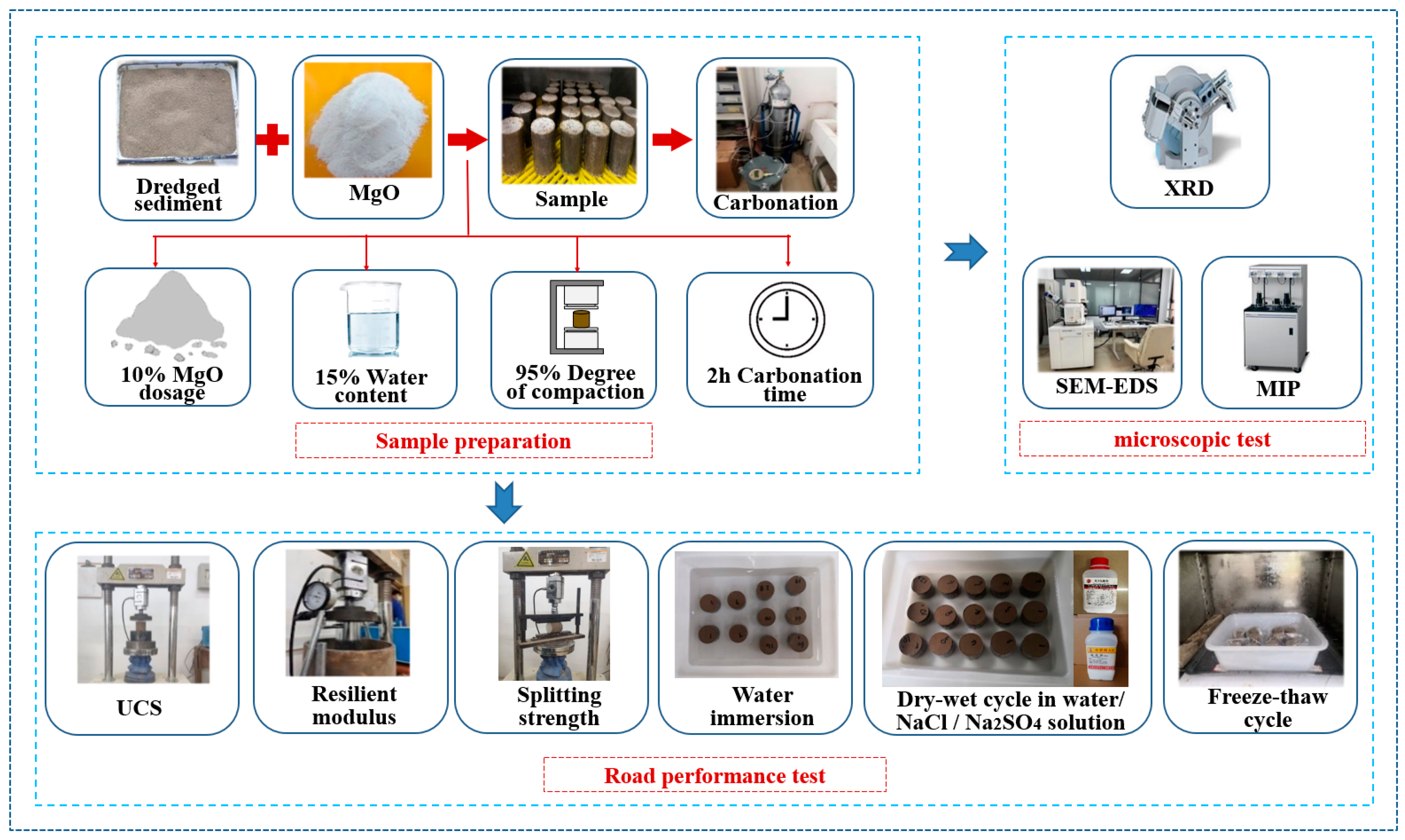
2. Materials and Methods

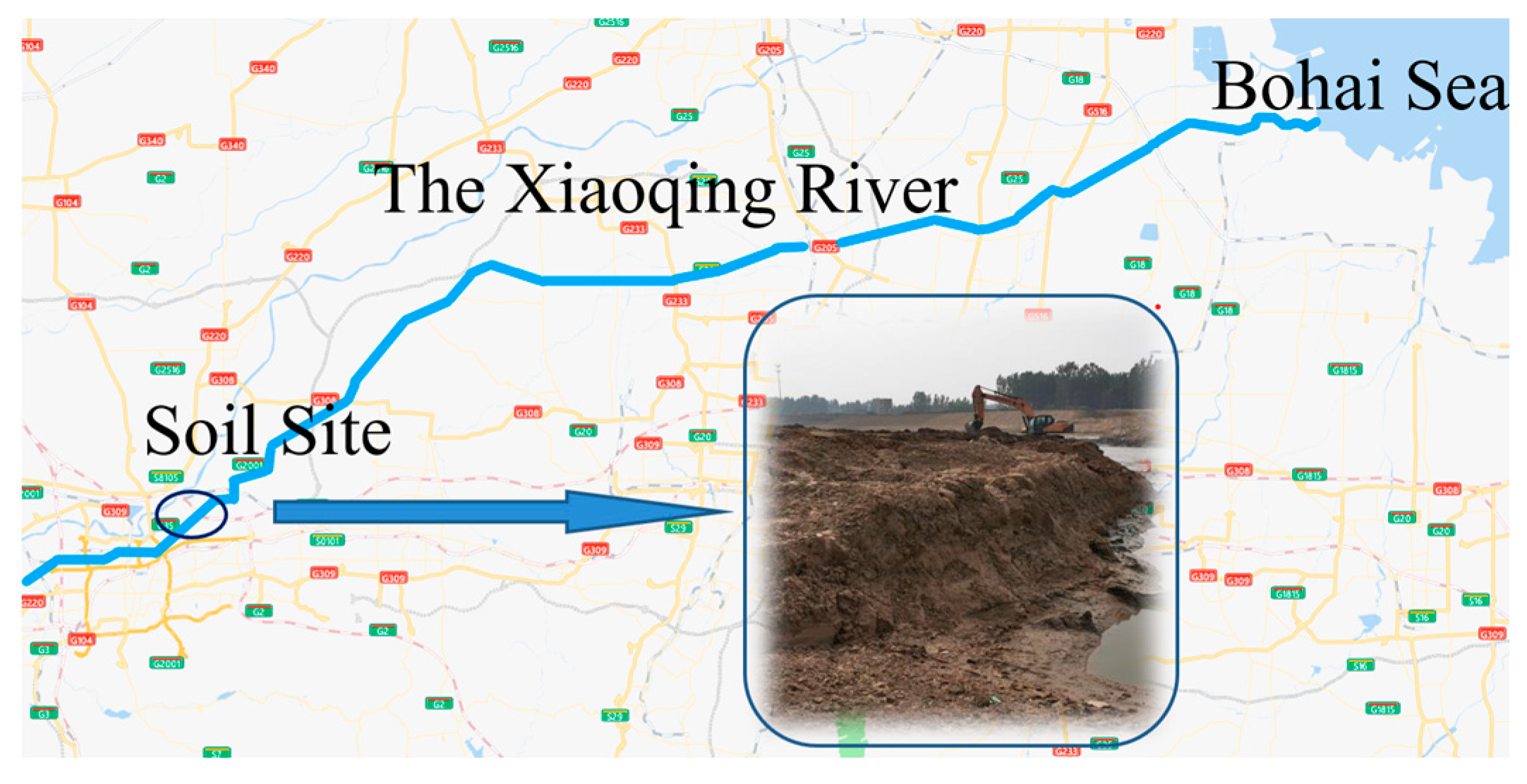
2.1. Testing Materials

The Xiaoqing River is part of the Bohai Sea water system, located in the middle of Shandong Province within the Yellow River basin. It spans a total length of 237 km and serves as a multi-purpose river for flood control, irrigation, and navigation. The sediment was collected from The Xiaoqing River flood control project in the north of Jinan City, China (Figure 1). The soil samples collected had a yellowish-brown color, and their initial water content was relatively low at 17.9%. This can be attributed to the fact that the sediment had been previously dried on the riverbank before sampling. The basic properties of the sediment are shown in Table 1.
The active MgO is produced by a chemical plant in Fengxian, Shanghai. It is a white powder, the average particle size is less than 5 μm, and the specific surface area is 72 m2/g. The content of active MgO is 73.2% by hydration method, which has good reactivity. The main compositions of the active MgO, as determined by XRF testing, are provided in Table 2.

2.2. Carbonation Device

The specimens were subjected to carbonation treatment using a self-developed small-scale carbonation furnace, as shown in Figure 2. The furnace was equipped with three layers of metal mesh to hold the specimens. The top cover of the furnace had an inlet and an outlet for air, along with a digital pressure gauge. The inlet was connected to a CO2 gas (the purity is 99.5%) cylinder through a ventilation pipe. The prepared specimens were carefully placed on the metal mesh layer inside the carbonation furnace, and the top cover was secured by tightening the bolts. Subsequently, the CO2 gas cylinder was opened for ventilation, and the exhaust vent was also opened to release the air from the furnace, maintaining a pressure of 50 kPa for 1 min. After venting the air, the exhaust vent was closed, and the ventilation was adjusted to the specified pressure using a pressure relief valve to maintain the pressure. At this point, the carbonation time was initiated. Once the designated carbonation time was reached, the exhaust vent was slowly opened, and when the pressure gauge displayed “0”, the specimens were removed, completing the carbonation process.

2.3. Testing Scheme and Methods

Based on the preliminary experimental results of this study, the optimal carbonation conditions were determined as follows: a 10% MgO content (by mass ratio of MgO to dry soil), a 15% soil moisture content (by mass ratio of water to dry material), and a compaction degree of 95% (by mass ratio of dry density to maximum dry density of mixture) for specimen preparation. The specimens were then subjected to carbonation by applying a pressure of 200 kPa in a carbonation vessel for a duration of 2 h. After accurately calculating the mass proportions of each component, they were mixed thoroughly and then prepared into cylindrical specimens with dimensions of ϕ50 mm × 50 mm using the static compaction method. For the non-carbonated specimens, after demolding, they were demolded and placed in standard curing chambers (temperature of 20 °C ± 2 °C, humidity ≥ 95%) for curing periods of 1 day, 7 days, 14 days, and 28 days, respectively. For the carbonated specimens, their weights were measured after demolding, and subsequently, the carbonation tests were conducted according to the specified carbonation times in the experimental plan. After the completion of carbonation, the specimens were weighed again, and the difference in weight before and after carbonation represented the amount of CO2 adsorbed.
After the curing or carbonation process, the specimens were subjected to X-ray Diffraction (XRD), Scanning Electron Microscope–Energy Dispersive Spectrometer (SEM-EDS), and Mercury-in-Pressure (MIP) tests. These tests aimed to analyze the hydration products, carbonation products, and microscopic structure of the solidified sediment. By exploring the microscopic characteristics and evolution patterns, the mechanism of MgO carbonation–solidification was investigated. Subsequently, the specimens underwent rebound modulus tests, splitting tests, immersion tests, coupled dry–wet cycle, salt solution erosion tests, and freeze–thaw cycle tests to study their mechanical properties and durability. The overall test flow is shown in Figure 3. It should be noted that for the tests conducted on the non-carbonated sediment, specimens cured for 7 days were used.

2.3.1. X-ray Diffraction (XRD) Test

The specimens were obtained from the fractured UCS test specimens. After drying, the samples were retrieved and subjected to grinding, followed by sieving through a 0.075 mm mesh sieve. X-ray diffraction (XRD) testing was conducted using the MiniFlex X-ray diffractometer (RIKAGU, Tokyo, Japan)to analyze the variations in hydration products and carbonation products in the carbonized and solidified sediment.

2.3.2. Scanning Electron Microscope–Energy Dispersive Spectrometer (SEM-EDS) Test

The equipment used is the GeminiSEM 300 (ZEISS, Oberkochen, Germany). The specimens were obtained from the unbroken portion of the UCS test specimens after completion of the test. They were cut into approximately 1 cm3 small cubes and dried. Prior to the experiment, the specimens were fractured, and clean and neat small soil particles from the fracture surface were selected for gold coating. The gold-coated specimens were then placed inside the scanning electron microscope (SEM) for observation after vacuum evacuation.

2.3.3. Mercury Intrusion Porosimetry (MIP) Test

In order to study the changes in the internal pore structure of the sediment before and after carbonation, mercury intrusion porosimetry (MIP) tests were conducted using an Autopore IV 9500 instrument (MICROMERITICS, Norcross, GA, USA). After the samples were dried, they were fractured to form small test specimens with natural fracture surfaces. These test specimens were then placed in the mercury intrusion porosimeter for testing.

2.3.4. Unconfined Compressive Strength (UCS) Test

In order to investigate the mechanical strength properties of carbonized and solidified sediment under different conditions, the unconfined compressive strength (UCS) tests were performed on specimens that had reached the designated curing age or carbonation time. The tests were conducted using a road strength meter, with a loading rate set at 1 mm/min.

2.3.5. Resilient Modulus Test

The specimens that had reached the designated carbonation time or curing age were placed on the lifting platform of a strength tester. The height of the lifting platform was adjusted, and displacement sensors were installed. Two preloading cycles were performed using half of the maximum load, with each preloading cycle lasting 1 min. The maximum pressure was divided into 5 equal increments, which were used as the pressure values for each loading cycle. Each load level was applied for 1 min, and the readings from the displacement sensors were recorded. Simultaneously, unloading was performed to restore the elastic deformation of the specimen. After unloading for 30 s, the readings were recorded again, and the next load level was applied. This process was repeated for each load level until the 5th unloading cycle was completed, and the readings were recorded.

2.3.6. Splitting Test

The specimens were placed on the lifting platform of the universal pavement material strength meter, the clamps required for the splitting test were installed, and the specimens were placed on the batten to ensure that the upper and lower batten were in close contact with the specimens, and the maximum failure pressure of the specimens was loaded and recorded.

2.3.7. Immersion Test

The test followed a complete immersion method, where the specimens were fully submerged in distilled water. The water surface was maintained 3 to 5 cm above the specimens throughout the test. The immersion time was 1 d, 7 d, 14 d, 28 d, 60 d, and 90 d, respectively.

2.3.8. Coupled Dry–Wet Cycle and Salt Solution Erosion Test

NaCl solution with a 5% mass fraction and Na2SO4 solution with a 5% mass fraction were configured, and water was set as control. The specimens were placed in NaCl solution, Na2SO4 solution, and water, and the solutions were changed to the same concentration every 3 days to ensure the stability of the solution concentration. The specimens were placed in a thermostatic chamber and allowed to dry for 12 h, constituting one dry cycle. Subsequently, the specimens were fully immersed in a solution for 12 h, constituting one wet cycle. This wet–dry cycle was repeated 20 times in total.

2.3.9. Freeze–Thaw Cycle Test

The specimens were placed in a −18 °C low-temperature box for 16 h, and then the specimens were removed and quickly melted in the tank of the standard curing box for 8 h, which was a freeze–thaw cycle.

3. Microscopic Mechanism

3.1. Analysis of Microscopic Characteristics

XRD, EDS, SEM, and MIP tests were conducted on the samples of dredged sediment, non-carbonated sediment, and carbonated sediment to investigate the evolving characteristics of mineral composition, microstructure, and pore structure under the carbonation process.

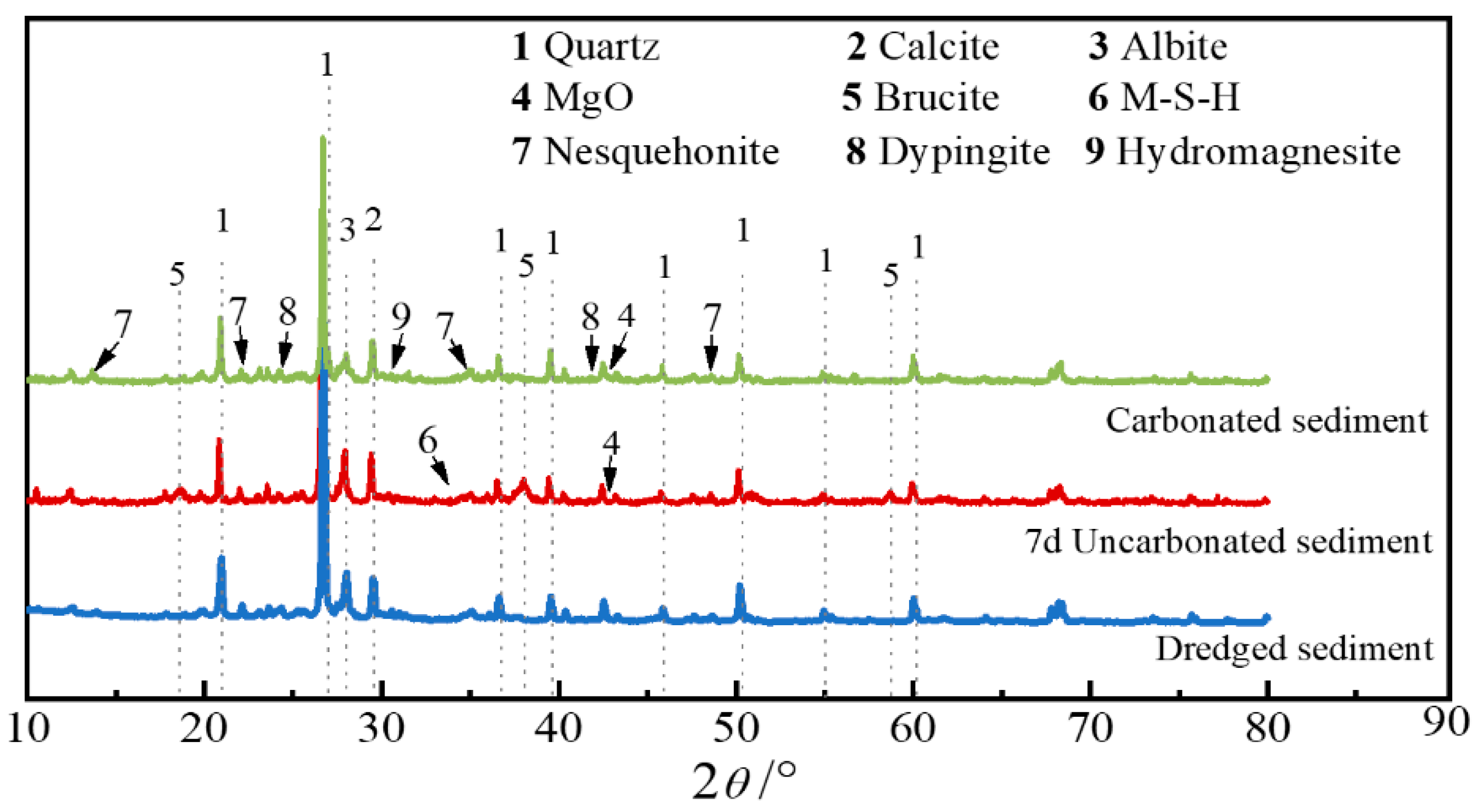
3.1.1. XRD Test Analysis

The results of X-ray diffraction (XRD) analysis are shown in Figure 4. Based on the comparison of different XRD spectra, it can be seen that, in addition to quartz (SiO2), calcite (CaCO3) and albite (Na(AlSi3O8)) are contained in the natural dredged sediment, the phases in the non-carbonated sediment are dominated by brucite (Mg(OH)2) and magnesium silicate hydrate (M-S-H), which are produced by the hydration reaction of the MgO doped into the soil body and the reaction of the volcanic ash. Whereas diffraction peaks of minerals such as dypingite (Mg5(CO3)4(OH)2-5H2O), hydromagnesite (Mg5(CO3)4(OH)2-4H2O), and nesquehonite (MgCO3-3H2O) are observed in the plots of the carbonized substrate. And the peak intensity of hydration product hydromagnesite is greatly reduced. It can be inferred that the brucite in the carbonized sediment had a carbonation reaction with CO2, which led to the decrease in the peak value of brucite and the appearance of the diffraction peaks of magnesium carbonate and other carbonation products.

3.1.2. EDS Energy Spectrum Analysis

In order to further verify the XRD analysis of the microproducts, EDS energy spectroscopy was carried out on the characteristic areas in the non-carbonated and carbonized sediment specimens, respectively, and the test results are shown in Figure 5. Figure 5a shows a scanning analysis of the area of flake product accumulation in the non-carbonated sediment, which shows that the flake product is mainly composed of O, Mg, and Si elements. Combined with the results of XRD and SEM tests, it can be determined that the flake product is hydromagnesite, and the appearance of Si peaks here indicates that the region contains partially hydrated magnesium silicate. Figure 5b shows the results of the analysis of the gel-like product in the non-carbonated sediment, and the main elements in this region are also O, Mg, and Si. Considering the atomic ratio of Mg/Si and combined with the microscopic morphology, it can be determined that the gel-like product here is hydrated magnesium silicate. Scanning analyses were performed on the floral and prismatic products in the carbonized sediment specimens, and the results are shown in Figure 5c and Figure 5d, respectively. From the analysis results, it can be seen that the elemental compositions of the two carbonized products are dominated by C, O, and Mg, indicating that they are both magnesium carbonates. Based on the existing research reports, combined with the microscopic morphology and elemental composition of the two products, it was possible to determine that the florid bone-shaped product is dypingite/hydromagnesite, and the prismatic one is nesquehonite.

3.1.3. SEM Test Analysis

Through the scanning electron microscope test to observe the microstructure of different sediment specimens, the test results are shown in Figure 6. From the microstructure of the dredged sediment, it can be seen that the sediment particles are large and scattered, the soil structure is poorly integrated, there are more pores and cracks, and the macro-performance is poor mechanical properties. In the non-carbonated sediment, there are a large number of loose and disordered gel-like and flaky hydration products around the soil particles, which are mainly hydromagnesite and hydrated magnesium silicate, as shown by XRD and EDS analyses. Hydration products are bonded or filled in the surface and interlayer of soil particles, forming an agglomerate structure dominated by line-face contact, but because the connection between the agglomerates is not close, there are still many pores in the structure of the soil of the non-carbonated sediment, and the integrality is not strong, so the effect of the improvement of the strength of the sediment is very limited. In the microscopic image of carbonized sediment, not only can we find the hydration products generated in the soil structure, but also clearly see the development of nesquehonite, flower-bone-like hydromagnesite and dypingite between the pores of soil particles, and the filling and cementing effect of these hydration products and carbonation products connects the loose and disordered soil particles into a whole, which greatly reduces the pore space and fissure of the soil, and improves the stability of the soil microscopic structure. Compared with the non-carbonated sediment, the reaction products in the microstructure of carbonized subsoil are more abundant, and these reaction products intertwine with each other to cement the surrounding soil particles, which greatly improves the degree of densification of the soil structure. Hence, the carbonation treatment has a more significant effect on the enhancement of the strength of the sediment.

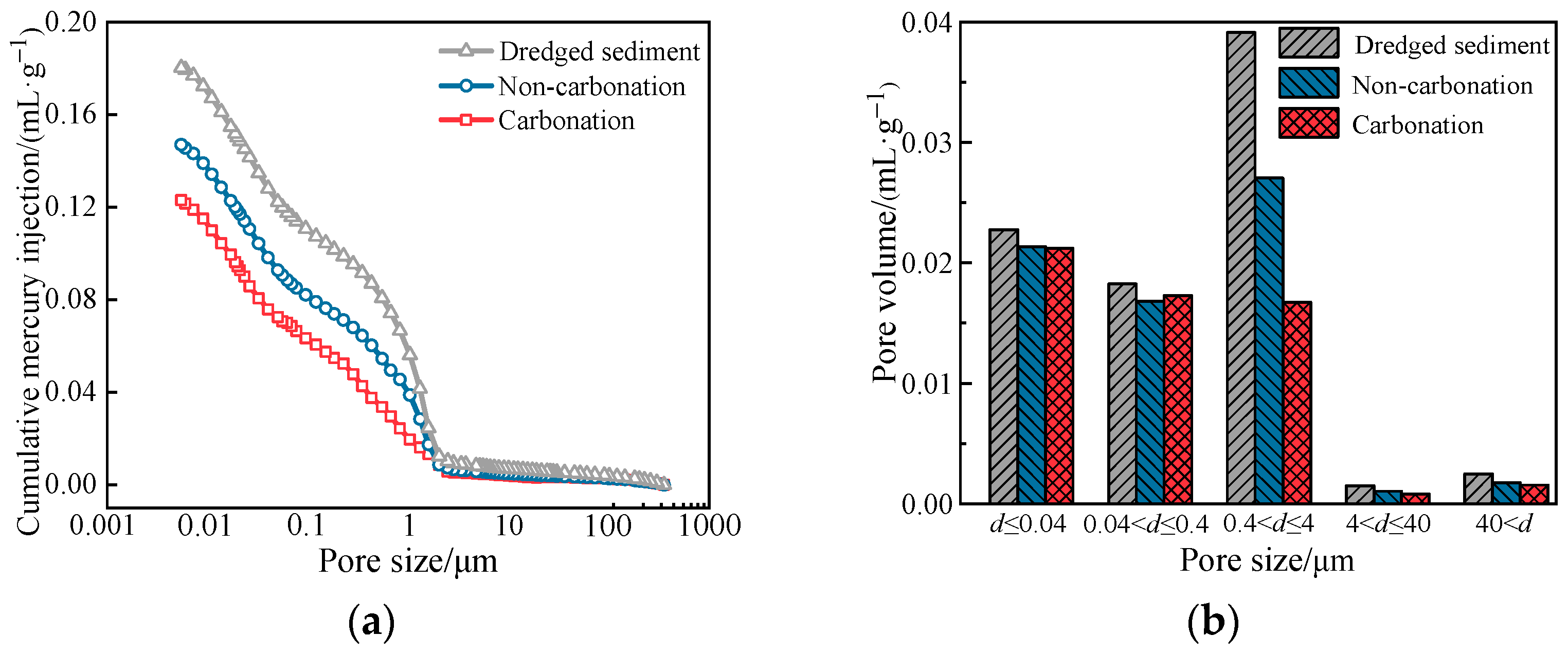
3.1.4. MIP Test Analysis

The internal pore structure of the sediment under different conditions was quantitatively analyzed by mercury compression test, and the results are shown in Figure 7. Based on Figure 7a, it can be observed that the cumulative mercury intrusion volumes for the non-carbonated sediment and carbonated sediment are 0.147 mL/g and 0.122 mL/g, respectively. Compared to the dredged sediment’s value of 0.180 mL/g, they represent reductions of 18.3% and 32.2%, respectively. This indicates that both the hydration and carbonation processes of MgO can improve the internal pore structure of the sediment, with carbonation showing a more pronounced effect.
The volume corresponding to the pores of various sizes (difference of cumulative mercury intake among the pore diameter intervals) is shown in Figure 7b. From Figure 7b, it can be seen that the pore types in the dredged sediment are mainly dominated by 0.4 μm < d ≤ 4 μm, and the volume of this size decreases most significantly after carbonation. Combined with the results of XRD and SEM tests, it can be seen that the reduction in the pore volume in the non-carbonated sediment mainly depends on the hydration of MgO produced by the hydrated magnesite and hydrated magnesium silicate; the two kinds of hydration products are filled and cemented between the soil particles, which effectively improves the pore structure of the soil body. Carbonized sediment, on the other hand, is on the basis of hydration; the hydration products react with CO2 to generate carbonized products, which can further fill the pore space of the soil and refine the pore structure, so the carbonation effect on the filling of the pore space is more significant, which is the same as the development of the law of the strength of the soil body.

3.2. Mechanism Analysis

Combining the results of the above microscopic characterization tests, we propose a model of the microscopic mechanism of the activated MgO carbonation–solidification of dredged sediment (Figure 8); and the carbonation–solidification process consists of two phases.
Stage ①: Mix MgO with dry sediment and add water; MgO rapidly undergoes a hydration reaction, producing a large amount of Mg2+ and OH. As the concentration of Mg2+ and OH rises, the weakly cemented product of magnesite (Mg(OH)2) in the form of irregular flakes is gradually precipitated. Magnesite can improve the bonding between soil particles and fill some of the intergranular pores to achieve a certain solidification effect, as well as participate in the subsequent carbonation reaction as a reactant.
Stage ②: CO2 is introduced into the soil, CO2 is rapidly absorbed by water in the soil to form CO32−, and then the hydration product Mg(OH)2 undergoes a series of carbonation reactions with CO32−, forming prismatic nesquehonite and part of the flower-bone-like hydromagnesite or dypingite. Carbonation products are of high strength, and with the growth and development of these crystals and increased generation, they cross each other to grow, build a stable skeleton structure, and through the role of cementing and filling, the soil particles cohesion into a group, thus forming a very dense microstructure, macroscopically manifested as a carbonized specimen of the strength of the significant enhancement.

4. Road Performance

4.1. Mechanical Properties

The rebound modulus and splitting strength of the dredged sediment, non-carbonated sediment (cured for 7 days), and carbonized sediment (2 h carbonation time) are shown in Figure 9. From the graph, it can be observed that the carbonized sediment exhibits a higher rebound modulus of 537 MPa compared to the dredged sediment (38 MPa) and non-carbonated sediment (152 MPa). This indicates that the carbonated sediment exhibits a significantly better elastic response. Additionally, the splitting strength of the carbonized sediment (0.69 MPa) is significantly higher than that of the dredged sediment (0.01 MPa) and non-carbonated sediment (0.32 MPa), demonstrating the effective enhancement of crack resistance through carbonation. Considering the microstructural mechanism mentioned earlier, the main reason for the improved mechanical performance of the carbonated sediment is that the hydration products can effectively improve the pore structure between some soil particles. The magnesium carbonate generated during carbonation can further interlock and compact the soil particles, resulting in a denser microstructure of the sediment.

4.2. Durability

4.2.1. Immersion Test

The comparison of the appearance of carbonated and non-carbonated sediment after 90 days of immersion is shown in Figure 10. It can be observed that both specimens have relatively intact appearances. After 90 days of immersion, the surface particles of both are less lost, remain relatively smooth, and have no cracks, holes, or spalling.
The compressive strength variations of the carbonated and non-carbonated sediment after different durations of immersion are depicted in Figure 11. With increasing immersion time, both specimens show a similar trend of initial rapid decrease in compressive strength from 1 to 14 days, followed by a slow decrease. However, after 90 days of immersion, the compressive strength of the carbonated sediment (3.32 MPa) is 1.96 times higher than that of the non-carbonated sediment (1.69 MPa). This demonstrates that carbonation–solidification of dredged sediment using MgO exhibits good long-term stability under immersion conditions.

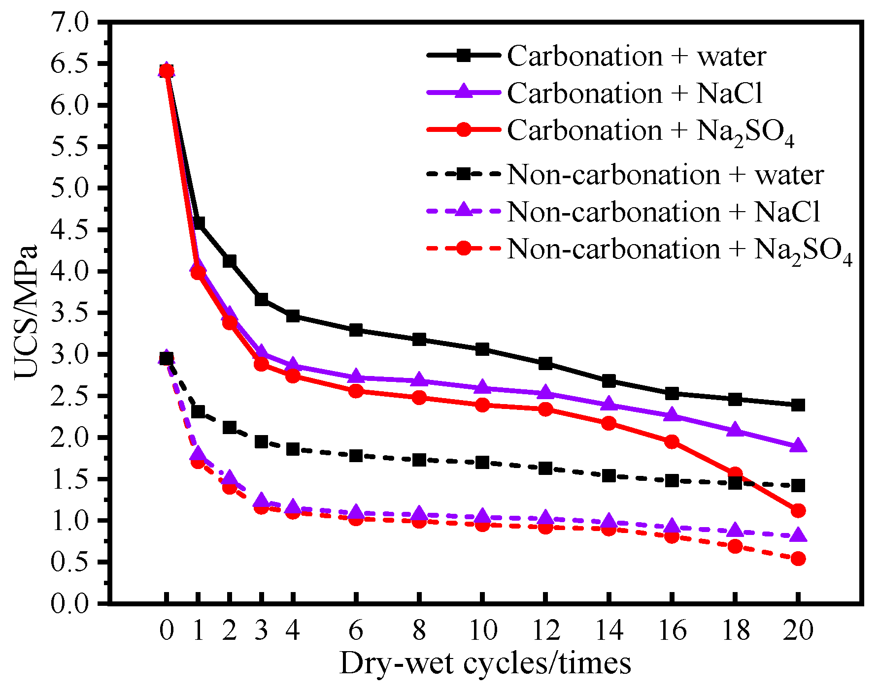
4.2.2. Coupled Dry–Wet Cycle and Salt Solution Erosion Test

Figure 12 illustrates the visual changes of carbonized sediment and non-carbonated sediment after 20 cycles of dry–wet conditions in water, NaCl solution, and Na2SO4 solution. From the graph, it can be observed that the visual changes in carbonized sediment are minimal in water and NaCl solutions. The carbonized sediment retains a clearer outline and a smoother surface compared to the non-carbonated sediment. However, in the Na2SO4 solution, the morphological changes are more pronounced. The carbonized sediment exhibits significant patchy peeling on its outer surface, indicating noticeable deterioration in appearance. On the other hand, the non-carbonated sediment shows extensive loss of material, with the surface layer mostly detached and lost, resulting in a loss of integrity.
Figure 13 presents the UCS of carbonized and non-carbonated sediment after undergoing dry–wet cycles in different solutions. Overall, both carbonized sediment and non-carbonated sediment exhibit a decreasing trend in strength, with a more pronounced effect observed in NaCl and Na2SO4 solutions. By comparing the two, it can be seen from Figure 13 that despite the greater degradation in strength for carbonized sediment, its residual strength (2.39 MPa, 1.89 MPa, 1.12 MPa) in water, NaCl, and Na2SO4 solutions is still higher than the residual strength of non-carbonated sediment (1.42 MPa, 0.81 MPa, 0.54 MPa) in the same solutions. This indicates that carbonation has a positive effect on the resistance of sediment to wet–dry corrosion in salt solutions.

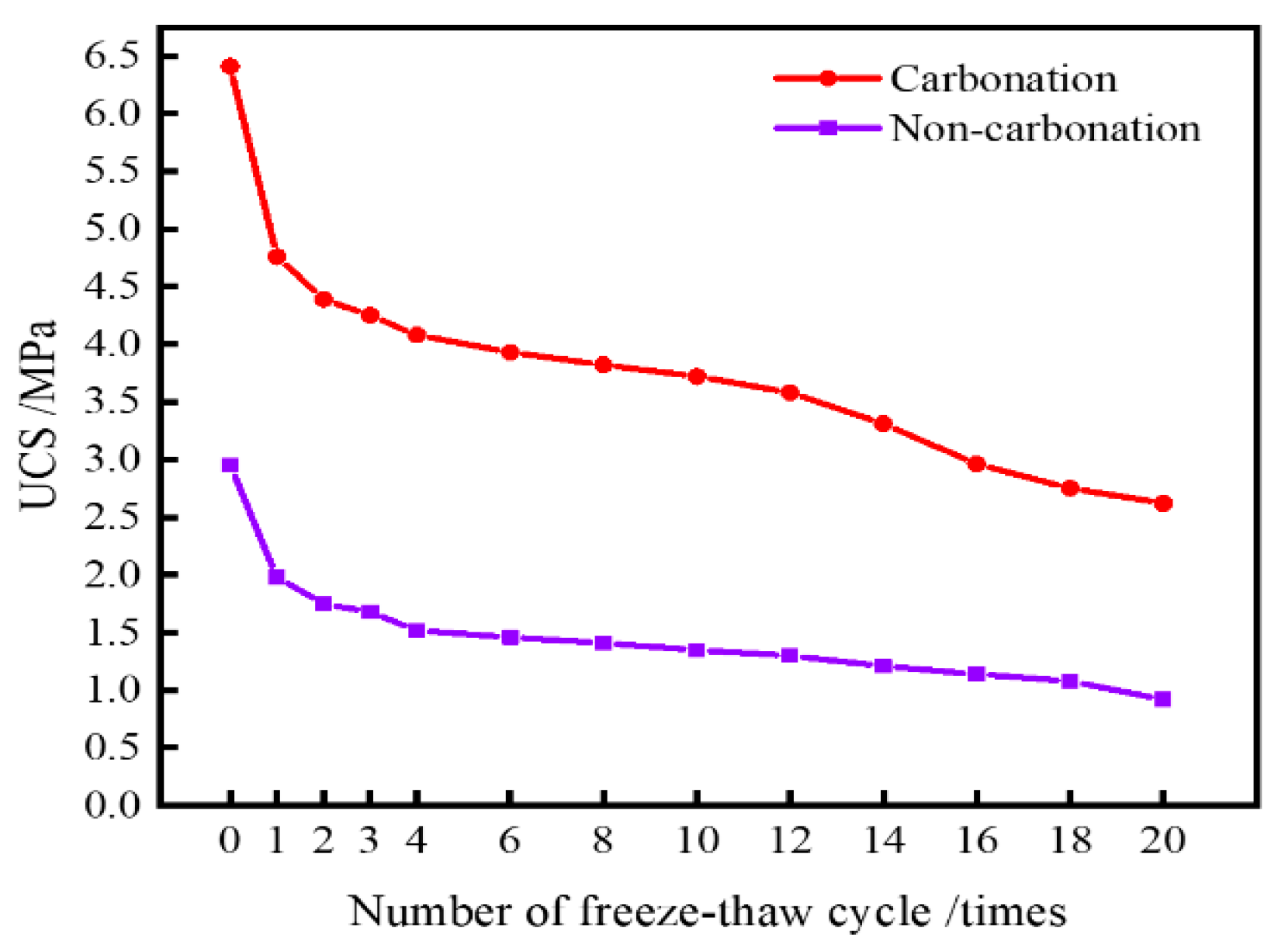
4.2.3. Freeze–Thaw Cycle Test

Figure 14 illustrates the visual comparison of carbonized sediment and non-carbonated sediment after undergoing 20 freeze–thaw cycles. From the graph, it can be observed that with the progression of freeze–thaw cycles, the surface of the non-carbonated sediment gradually develops micropores due to erosion and particle loss. In contrast, the appearance of the carbonized sediment undergoes minimal changes, remaining intact and maintaining a good overall condition.
Figure 15 presents the UCS of carbonized sediment and non-carbonated sediment under different numbers of freeze–thaw cycles. It can be observed that both carbonated and non-carbonated sediment experience a decrease in strength to varying degrees, with the lowest strengths recorded after the 20th cycle, measuring 2.62 MPa and 0.92 MPa, respectively. With an increase in the number of freeze–thaw cycles, the alternating freezing and melting of pore water, as well as the periodic erosion and frost heave, have gradually led to a decrease in compressive strength for both sediments.

5. Conclusions

This study introduces the MgO carbonation technique for the solidification and improvement of dredged sediment. Through XRD tests, SEM-EDS analysis, and MIP tests, the evolution characteristics of the internal mineral composition, microscopic morphology, and pore structure of the carbonated soil are systematically investigated. The aim is to explore the mechanism of MgO carbonation–solidification of dredged sediment at the microscopic level. Additionally, rebound modulus tests, splitting tests, immersion tests, coupled dry–wet cycle and salt solution erosion tests, and freeze–thaw cycle tests were conducted to evaluate the mechanical properties and durability performance of the specimens under the optimal carbonation conditions. The main conclusions are as follows:
(1)
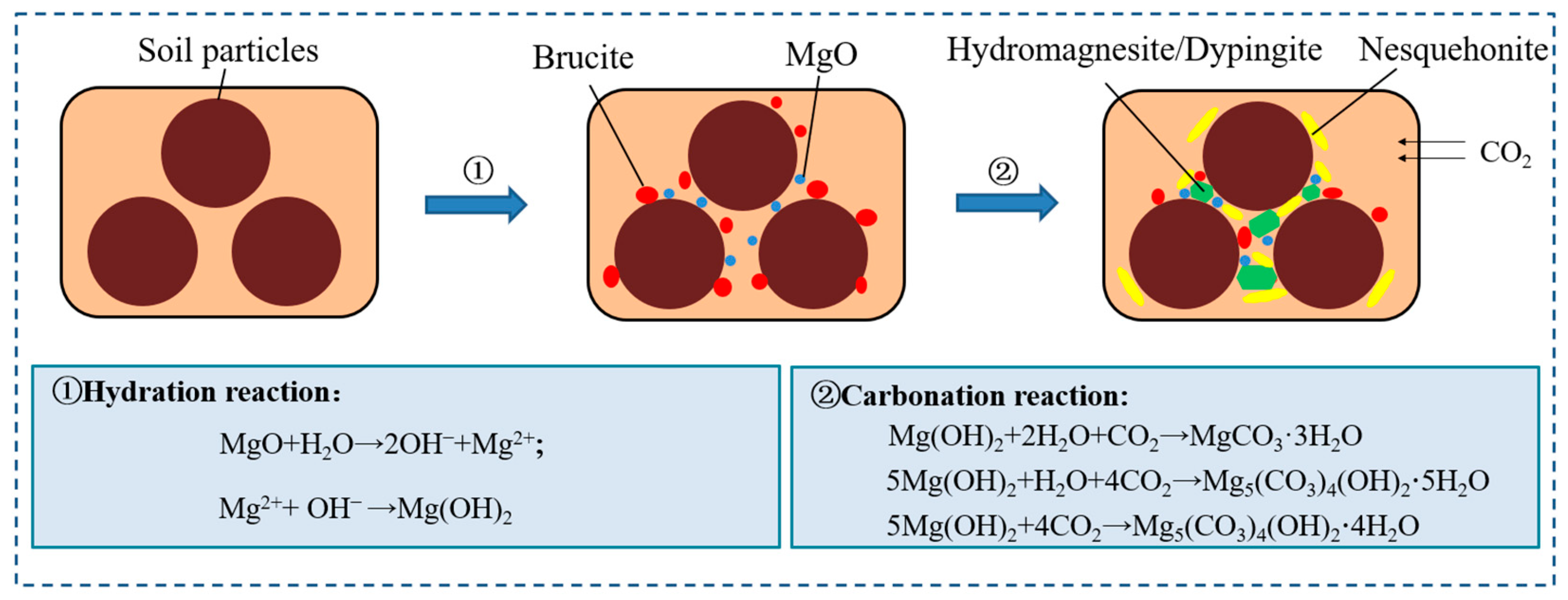
MgO carbonation has a significant improvement effect on sediment. The encapsulation, bonding, and filling effects of hydration and carbonation products can greatly reduce the pore volume in the sediment, leading to a more stable microstructural arrangement of the soil.
(2)
For non-carbonated sediment, the formation of hydrated products such as brucite (Mg(OH)2) and magnesium silicate hydrate (M-S-H) is the fundamental reason for strength improvement. However, for carbonated sediment, the strength improvement is mainly attributed to the formation of dypingite (Mg5(CO3)4(OH)2-5H2O), hydromagnesite (Mg5(CO3)4(OH)2-4H2O), and nesquehonite (MgCO3-3H2O) through the carbonation reaction of brucite.
(3)
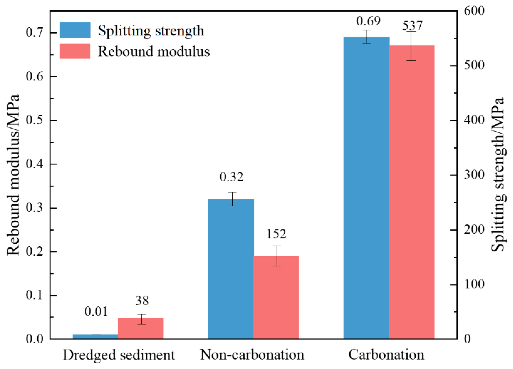
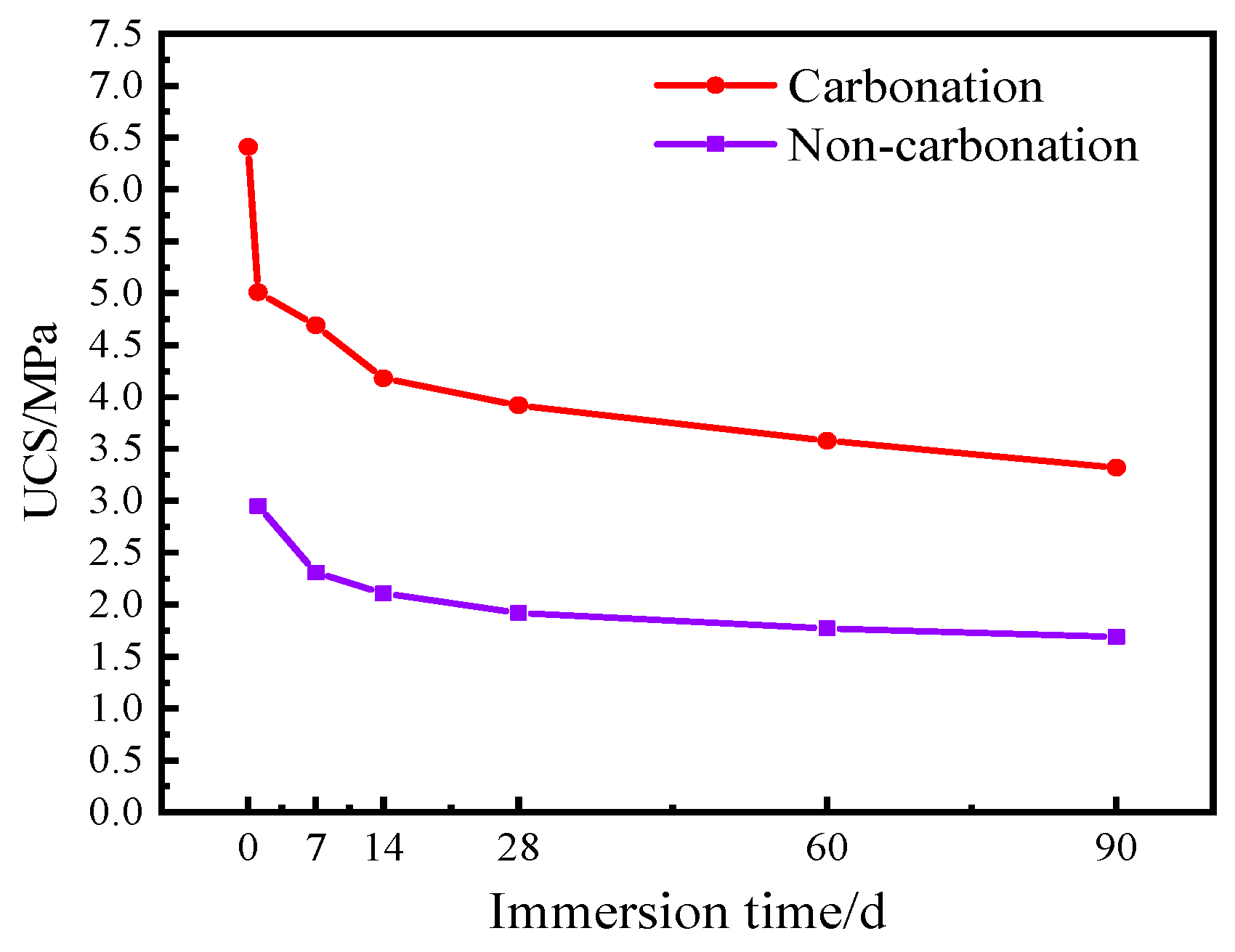
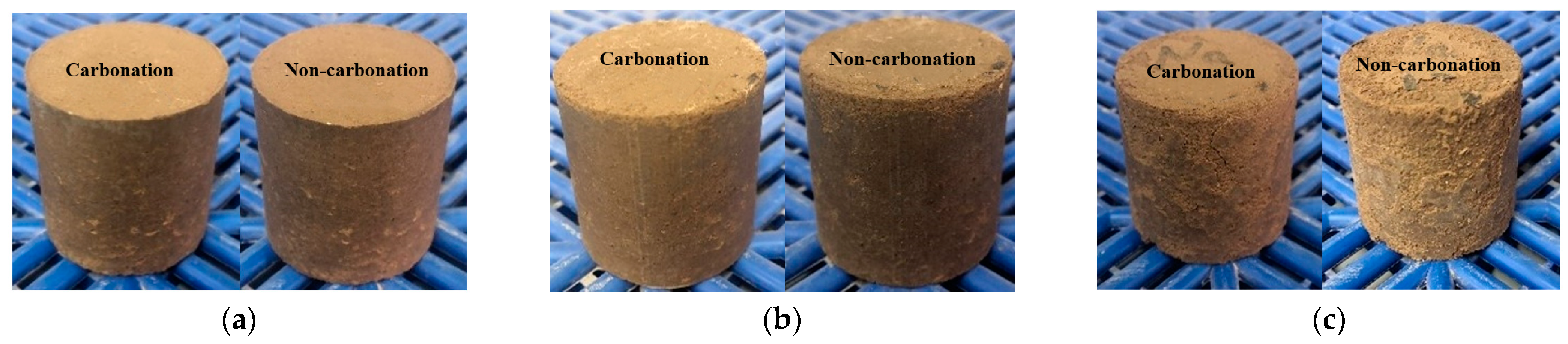
The carbonation process has a positive impact on the mechanical properties and durability of dredged sediment. The rebound modulus and splitting strength of carbonated sediment were 3.53 times and 2.16 times that of non-carbonated sediment, respectively. For carbonized specimens, the strength was 3.32 MPa after 90 days of water saturation. The strength was 2.39 MPa, 1.89 MPa, and 1.12 MPa after 20 times of dry–wet cycles in water, NaCl, and Na2SO4 solutions, respectively. The strength was 2.62 MPa after 20 times of freeze–thaw cycles. It can be seen that carbonation is beneficial for improving the road performance of sediment.

Author Contributions

Conceptualization, X.K.; methodology, X.K.; validation, Z.Z.; formal analysis, A.S.; investigation, L.Y.; data curation, B.X.; writing—original draft preparation, X.W.; writing—review and editing, X.K.; visualization, F.Z.; supervision, Z.Z.; project administration, Y.L.; funding acquisition, Z.Z. All authors have read and agreed to the published version of the manuscript.

Funding

This research was funded by the Taishan Scholar Foundation, the National Natural Science Foundation of China (No. 52070122), the Shandong Jianzhu University Graduate Education Quality Improvement Plan Construction Project, and 20 New University Projects in Jinan City (No. 202228056).

Institutional Review Board Statement

Not applicable.

Informed Consent Statement

Not applicable.

Data Availability Statement

Data is contained within the article.

Acknowledgments

We want to thank my colleagues and students of the School of Transportation Engineering of Shandong Jianzhu University for their help and their suggestions on the testing and writing of the article.

Conflicts of Interest

The authors declare no conflicts of interest.

References

  1. Svensson, N.; Noren, A.; Modin, O.; Fedje, K.; Rauch, S.; Stromvall, A.; Andersson-Skold, Y. Integrated cost and environmental impact assessment of management options for dredged sediment. Waste Manag. 2022, 138, 30–40. [Google Scholar] [CrossRef]
  2. Bianchini, A.; Cento, F.; Guzzini, A.; Pellegrini, M.; Saccani, C. Sediment management in coastal infrastructures: Techno-economic and environmental impact assessment of alternative technologies to dredging. J. Environ. Manag. 2019, 248, 109332. [Google Scholar] [CrossRef]
  3. Kong, X.; Zhang, Z.; Liang, Y.; Wang, X.; Liu, M. Experimental study on solidified dredged sediment with MgO and industrial waste residue. Constr. Build. Mater. 2023, 366, 130105. [Google Scholar] [CrossRef]
  4. Amar, M.; Benzerzour, M.; Kleib, J.; Abriak, N. From dredged sediment to supplementary cementitious material: Characterization, treatment, and reuse. Int. J. Sedim. Res. 2021, 36, 92–109. [Google Scholar] [CrossRef]
  5. Kumar, V.; Sharma, A.; Pandita, S.; Bhardwaj, R.; Thukral, A.; Cerda, A. A review of ecological risk assessment and associated health risks with heavy metals in sediment from India. Int. J. Sedim. Res. 2020, 35, 516–526. [Google Scholar] [CrossRef]
  6. Zhang, Y.; Labianca, C.; Chen, L.; Gisi, S.; Notarnicola, M.; Guo, B.; Sun, J.; Ding, S.; Wang, L. Sustainable ex-situ remediation of contaminated sediment: A review. Environ. Pollut. 2021, 287, 117333. [Google Scholar] [CrossRef]
  7. Wang, D.; Abriak, N.; Zentar, R. Dredged marine sediment used as novel supply of filling materials for road construction. Mar. Georesour. Geotechnol. 2017, 35, 472–480. [Google Scholar] [CrossRef]
  8. Chen, P.; Feng, B.; Lin, Y.; Lin, C. Solidification and stabilization of sewage sludge and MSWI bottom ash for beneficial use as construction materials. J. Mater. Civ. Eng. 2019, 31, 04018351. [Google Scholar] [CrossRef]
  9. Gao, S.; Chen, Y.; Chen, L.; Cheng, X.; Chen, G. Experimental and field study on treatment waste mud by in situ solidification. Munic. Eng. 2020, 173, 237–245. [Google Scholar] [CrossRef]
  10. Lang, L.; Liu, N.; Chen, B. Strength development of solidified dredged sludge containing humic acid with cement, lime and nano-SiO2. Constr. Build. Mater. 2020, 230, 116971. [Google Scholar] [CrossRef]
  11. Wang, S.; He, X.; Cai, G.; Lang, L.; Ma, H.; Gong, S.; Niu, Z. Investigation on water transformation and pore structure of cement-stabilized dredged sediment based on NMR technology. Materials 2022, 15, 3178. [Google Scholar] [CrossRef]
  12. Liu, F.; Zhu, C.; Yang, K.; Ni, J.; Hai, J.; Gao, S. Effects of fly ash and slag content on the solidification of river-dredged sludge. Mar. Georesour. Geotechnol. 2021, 39, 65–73. [Google Scholar] [CrossRef]
  13. Cheng, X.; Chen, Y.; Chen, G.; Li, B. Characterization and prediction for the strength development of cement stabilized dredged sediment. Mar. Georesour. Geotechnol. 2021, 39, 1015–1024. [Google Scholar] [CrossRef]
  14. Zentar, R.; Wang, H.; Wang, D. Comparative study of stabilization/solidification of dredged sediments with ordinary Portland cement and calcium sulfo-aluminate cement in the framework of valorization in road construction material. Constr. Build. Mater. 2021, 279, 122447. [Google Scholar] [CrossRef]
  15. Singh, R.; Budarayavalasa, S. Solidification and stabilization of hazardous wastes using geopolymers as sustainable binders. J. Mater. Cycles Waste 2021, 23, 1699–1725. [Google Scholar] [CrossRef]
  16. Shah, V.; Scott, A. Hydration and microstructural characteristics of MgO in the presence of metakaolin and silica fume. Cem. Concr. Compos. 2021, 121, 104068. [Google Scholar] [CrossRef]
  17. Yi, Y.; Lu, K.; Liu, S.; Al-Tabbaa, A. Property changes of reactive magnesia–stabilized soil subjected to forced carbonation. Can. Geotech. J. 2016, 53, 314–325. [Google Scholar] [CrossRef]
  18. Ruan, S.; Unluer, C. Comparative life cycle assessment of reactive MgO and Portland cement production. J. Clean. Prod. 2016, 137, 258–273. [Google Scholar] [CrossRef]
  19. Alavi, M.; Morsali, A. Syntheses and characterization of Mg(OH)2 and MgO nanostructures by ultrasonic method. Ultrason. Sonochem. 2010, 17, 441–446. [Google Scholar] [CrossRef]
  20. Harrison, J. New cements based on the addition of reactive magnesia to Portland cement with or without added pozzolan. In Proceedings of the CIA Conference: Concrete in the Third Millennium, CIA, Brisbane, Australia, 17–19 July 2003. [Google Scholar]
  21. Harrison, J. Reactive Magnesium Oxide Cements. U.S. Patent US2003041785, 6 March 2003. [Google Scholar]
  22. Yao, K.; Wang, W.; Li, N.; Zhang, C.; Wang, L. Investigation on Strength and Microstructure Characteristics of Nano-MgO Admixed with Cemented Soft Soil. Constr. Build. Mater. 2019, 206, 160–168. [Google Scholar] [CrossRef]
  23. Cai, G.; Du, Y.; Liu, S.; Singh, D. Physical properties, electrical resistivity, and strength characteristics of carbonated silty soil admixed with reactive magnesia. Can. Geotech. J. 2015, 52, 1699–1713. [Google Scholar] [CrossRef]
  24. Seo, J.; Yoon, H.; Kim, S.; Wang, Z.; Kil, T.; Lee, H. Characterization of reactive MgO-modified calcium sulfoaluminate cements upon carbonation. Cem. Concr. Res. 2021, 146, 106484. [Google Scholar] [CrossRef]
  25. Lu, B.; Shi, C.; Hou, G. Strength and microstructure of CO2 cured low-calcium clinker. Constr. Build. Mater. 2018, 188, 417–423. [Google Scholar] [CrossRef]
  26. Olajire, A. A review of mineral carbonation technology in sequestration of CO2. J. Pet. Sci. Eng. 2013, 109, 364–392. [Google Scholar] [CrossRef]
  27. Liu, Z.; Meng, W. Fundamental understanding of carbonation curing and durability of carbonation-cured cement-based composites: A review. J. CO2 Util. 2021, 44, 101428. [Google Scholar] [CrossRef]
  28. Rahmani, O. Siderite precipitation using by-product red gypsum for CO2 sequestration. J. CO2 Util. 2018, 24, 321–327. [Google Scholar] [CrossRef]
  29. Yi, Z.; Wang, T.; Guo, R. Sustainable building material from CO2 mineralization slag: Aggregate for concretes and effect of CO2 curing. J. CO2 Util. 2020, 40, 101196. [Google Scholar] [CrossRef]
  30. Kaliyavaradhan, S.K.; Ling, T.C.; Mo, K.H. CO2 sequestration of fresh concrete slurry waste: Optimization of CO2 uptake and feasible use as a potential cement binder. J. CO2 Util. 2020, 42, 101330. [Google Scholar] [CrossRef]
  31. Li, W.; Yi, Y. Stabilization/solidification of lead- and zinc-contaminated soils using MgO and CO2. J. CO2 Util. 2019, 33, 215–221. [Google Scholar] [CrossRef]
  32. Suescum-Morales, D.; Kalinowska-Wichrowska, K.; Fernandez, J.; Jimenez, J. Accelerated carbonation of fresh cement-based products containing recycled masonry aggregates for CO2 sequestration. J. CO2 Util. 2021, 46, 101461. [Google Scholar] [CrossRef]
  33. Li, Z.; He, Z.; Chen, X. The performance of carbonation-cured concrete. Materials 2019, 12, 3729. [Google Scholar] [CrossRef] [PubMed]
  34. Siddique, S.; Naqi, A.; Jang, J. Influence of water to cement ratio on CO2 uptake capacity of belite-rich cement upon exposure to carbonation curing. Cem. Concr. Compos. 2020, 111, 103616. [Google Scholar] [CrossRef]
  35. Shi, C.; Wu, Z.; Cao, Z.; Ling, T.; Zheng, J. Performance of mortar prepared with recycled concrete aggregate enhanced by CO2 and pozzolan slurry. Cem. Concr. Compos. 2018, 86, 130–138. [Google Scholar] [CrossRef]
  36. Wang, W.; Zhou, H.; Li, J.; Tao, F.; Li, C.; Qian, B.; Jiang, P. Influence of Carbonation Process on the Mechanical Properties of Nano-MgO Modified Cement Soil. Sustainability 2021, 13, 3558. [Google Scholar] [CrossRef]
  37. Yi, Y.; Liska, M.; Unluer, C.; Al-Tabbaa, A. Carbonating magnesia for soil stabilization. Can. Geotech. J. 2013, 50, 899–905. [Google Scholar] [CrossRef]
  38. Wang, D.; Xiao, J.; He, F.; Zhou, Y. Durability evolution and associated micro-mechanisms of carbonated reactive MgO-fly ash solidified sludge from East Lake, China. Constr. Build. Mater. 2019, 208, 1–12. [Google Scholar] [CrossRef]
  39. Liu, S.; Cai, G.; Cao, J.; Wang, F. Influence of soil type on strength and microstructure of carbonated reactive magnesia-treated soil. Eur. J. Environ. Civ. Eng. 2020, 24, 248–266. [Google Scholar] [CrossRef]
  40. Dung, N.; Unluer, C. Performance of reactive MgO concrete under increased CO2 dissolution. Cem. Concr. Res. 2019, 118, 92–101. [Google Scholar] [CrossRef]
  41. Yang, Y.; Ruan, S.; Wu, S.; Chu, J.; Unluer, C.; Liu, H.; Cheng, L. Biocarbonation of reactive magnesia for soil improvement. Acta Geotech. 2020, 16, 1113–1125. [Google Scholar] [CrossRef]
  42. Xiao, X.; Goh, L.; Unluer, C.; Yang, E. Bacteria-induced internal carbonation of reactive magnesia cement. Constr. Build. Mater. 2021, 267, 121748. [Google Scholar] [CrossRef]
  43. Liska, M.; AI-Tabbaa, A. Performance of magnesia cements in porous blocks in acid and magnesium environments. Adv. Cem. Res. 2012, 24, 221–232. [Google Scholar] [CrossRef]
  44. Zhang, X.; Liu, S.; Wu, K.; Yuan, Z. Experimental investigation into the self-carbonation mechanism of magnesium oxide carbon sequestration foamed concrete. Cem. Concr. Compos. 2024, 148, 105486. [Google Scholar] [CrossRef]
Figure 1. The Xiaoqing River basin.
Sustainability 16 05097 g001
Figure 2. Carbonation kettle.
Sustainability 16 05097 g002
Figure 3. Overall testing program.
Sustainability 16 05097 g003
Figure 4. XRD spectrum analysis.
Sustainability 16 05097 g004
Figure 5. EDS spectrum analysis: (a) Uncarbonated sediment-flake products; (b) Uncarbonated sediment-gel products; (c) Carbonated sediment–flower-bone-like products; (d) Carbonated sediment-elongated prismatic products.
Sustainability 16 05097 g005
Figure 6. SEM image of uncarbonated and carbonated sediment (×5000): (a) Dredged sediment; (b) Uncarbonated sediment; (c) Carbonated sediment.
Sustainability 16 05097 g006
Figure 7. Effect of carbonation and solidification on internal porosity of specimens: (a) Cumulative mercury injection; (b) Variation of pore volume.
Sustainability 16 05097 g007
Figure 8. Micro-mechanism model of MgO carbonation and solidification.
Sustainability 16 05097 g008
Figure 9. Rebound modulus and splitting strength.
Sustainability 16 05097 g009
Figure 10. Appearance comparison after 90 days of immersion.
Sustainability 16 05097 g010
Figure 11. Influence of immersion time on UCS.
Sustainability 16 05097 g011
Figure 12. Appearance comparison after dry–wet cycles in different solutions. (a) Water and (b) 5%NaCl solution and (c) 5%Na2SO4 solution.
Sustainability 16 05097 g012
Figure 13. Influence of dry–wet cycles on UCS.
Sustainability 16 05097 g013
Figure 14. Appearance comparison after freeze–thaw cycles.
Sustainability 16 05097 g014
Figure 15. Influence of freeze–thaw cycles on UCS.
Sustainability 16 05097 g015
Table 1. Basic physical and mechanical properties of sediments.
PropertiesValue
Gs2.62
Liquid limit (%)29.3
Plastic limit (%)22.9
Plasticity index (%)6.4
Fine-grained group (<0.075 mm) (%)23.6
Sand group (0.075–2 mm) (%)62.7
Fine gravel group (2–5 mm) (%)13.7
Maximum dry density (g/cm³)1.93
Optimum water content (%)14.4
Unconfined compression strength (kPa)392.4
CBR (%)9.6
Resilient modulus (MPa)38
Table 2. Chemical composition of MgO.
CompositionMgOCaOFe2O3Al2O3LOI
Content (%)96.871.500.090.081.46
Notation: LOI = Loss on ignition.
Disclaimer/Publisher’s Note: The statements, opinions and data contained in all publications are solely those of the individual author(s) and contributor(s) and not of MDPI and/or the editor(s). MDPI and/or the editor(s) disclaim responsibility for any injury to people or property resulting from any ideas, methods, instructions or products referred to in the content.

