Article

Experimental Combustion of Different Biomass Wastes, Coals and Two Fuel Mixtures on a Fire Bench

by
Andrey Zhuikov
1,
Nikolay Zemlyanskiy
1,
Irina Grishina
1 and
Stanislav Chicherin
2,3,*
1
Laboratory of the Heat Engineering and Hydrogasodynamics Department, Polytechnic School, Siberian Federal University, Svobodny Ave., 79., Krasnoyarsk 660041, Russia
2
Thermo and Fluid Dynamics (FLOW), Faculty of Engineering, Vrije Universiteit Brussel (VUB), Pleinlaan 2, 1050 Brussels, Belgium
3
Brussels Institute for Thermal-Fluid Systems and Clean Energy (BRITE), Vrije Universiteit Brussel (VUB) and Université Libre de Bruxelles (ULB), 1050 Brussels, Belgium
*
Author to whom correspondence should be addressed.
Sustainability 2024, 16(12), 5227; https://doi.org/10.3390/su16125227
Submission received: 15 May 2024 / Revised: 13 June 2024 / Accepted: 17 June 2024 / Published: 19 June 2024

Abstract

:
When designing settlements according to the “Green Building” principle, it is necessary to develop a heating system based on climatic conditions. For example, in areas with a sharply continental climate (cold and prolonged winters), it is sometimes necessary to use solid fuel boilers (in the absence of gas). However, to use these, it is necessary to use biomass or biomass-coal blends as fuel to increase their combustion heat. The addition of biomass waste to coal can be aimed at achieving various objectives: utilization of biomass waste; reduction of solid fossil fuel consumption; improvement of environmental performance at coal-fired boiler houses; improvement of the reactivity of coals or to improve the technical and economic performance of heat-generating plants due to the fact that biomass is a waste from various types of production, and its cost depends only on the distance of its transportation to the boiler house. In this work, combustion of various biomass wastes, including sewage sludge, was carried out on a fire bench emulating the operation of a boiler furnace. Fuel particles were ignited by convective heat transfer in a stream of hot air at a velocity of 5 m/s in the temperature range of 500–800 °C, and the experimental process was recorded on a high-speed, color video camera. The obtained values were compared with the characteristics of different coals used in thermal power generation (lignite and bituminous coal). The aim of the work is to determine the reactivity of various types of biomass, including fuel mixtures based on coal and food waste. The work presents the results of technical and elemental analysis of the researched fuels. Scanning electron microscopy was used to analyze the fuel particle surfaces for the presence of pores, cracks and channels. It was found that the lowest ignition delay is characteristic of cedar needles and hydrolyzed lignin; it is four times less than that of lignite coal and nine times less than that of bituminous coal. The addition of hydrolysis lignin to coal improves its combustion characteristics, while the addition of brewer’s spent grain, on the contrary, reduces it, increasing the ignition time delay due to the high moisture content of the fuel particles.

1. Introduction

Building heating issues are an integral part of the construction of modern urban neighborhoods according to the “Green Building” principle [1,2]. Basically, to heat buildings, this principle assumes the use of renewable energy sources within the framework of nearly zero-energy building (nZEB); for this purpose, fourth- and fifth-generation heating systems are used [3,4,5]. Such sources of thermal energy include electric boilers, heat pumps, pyrolysis reactors, etc. [6]. The principle of operation of a pyrolysis reactor is the thermochemical destruction of solid organic fuel. Most often, a pyrolysis reactor works in pair with a utilization boiler or with a small electric turbine (or with both at the same time) according to the co-generative principle, heating network water and generating electric energy. Such plants are environmentally friendly, as they produce minimal harmful emissions from combustion of coal-derived gas or in the form of fine mineral particles when compared to coal-fired boilers. Biomass waste or RDF (refuse-derived fuel from municipal solid waste) is mainly used as energy fuel for such systems [7,8,9,10]. Such units are inferior to traditional coal-fired boilers in terms of thermal energy output and are usually used in areas with moderate and warm climates.
In areas of coal basins and extreme continental climate characterized by cold and long winters, coal continues to be used as the main energy fuel due to its low cost and high calorific value compared to other types of solid fuels. Coal combustion emits a large amount of NOx, SOx and other harmful substances, including fine ash particles and CO2 [11,12,13,14]. The method proposed and implemented in many countries, which consists in adding various biomass wastes to coal, has proved to be a way out of a difficult situation that can lead to the shutdown of a coal-fired boiler or thermal power plant due to high levels of harmful emissions. The main advantages of switching to combustion of solid fuel mixture based on coal and biomass are as follows [15,16,17,18,19,20,21,22]:
  • Reduction of SOx and partly NOx emissions depending on the biomass type;
  • Reduction of coal consumption;
  • Low cost of biomass waste, depending only on the distance of its delivery to the boiler house;
  • Utilization of biomass waste;
  • Reduction of carbon dioxide emissions due to the fact that biomass is carbon neutral;
  • No need for high costs for reconstruction of boiler equipment;
  • Possibility of switching quickly back to coal combustion in case of interruptions or lack of supply of biomass waste;
  • Biomass is a highly reactive fuel.
When using biomass as an additional fuel, different purposes are pursued, such as the improvement of technical and economic indicators of boiler operation, improvement of environmental characteristics of boiler operation, utilization of biomass waste, improvement of characteristics of the combustion process of power fuel or for intensification of ignition of solid stoking fuel during oil-free combustion of a coal-fired boiler with the use of a muffle preheater [23]. A large number of scientific studies are devoted to the co-combustion of coal and biomass due to their great diversity and dependence on geographical location.
One of the most common types of biomass is wood due to its availability and relatively high heat of combustion compared to thermal coals. In [24], the combustion of brown coal and pine wood in a fluidized bed of catalyst at temperatures of 600–750 °C was studied, and it was found that increasing the wood biomass in the mixture affects the reduction of CO, CO2 and NOx in the flue gases. The co-combustion of mixtures based on food waste biochar (FWB) and coal was investigated in [25] using an experimental setup, and it was found that the addition of 10% FWB to coal had a positive effect on the reduction of nitrogen oxides. Jaworski, T.J. et al. [26] studied the combustion of wood, sewage sludge, RDF and their mixture. Different variants of individual and joint combustion of the considered fuels in the furnaces of boilers equipped with grates were proposed. Studying the combustion of two different coals together with agricultural wastes (rice husk, corn husk, sunflower disc and falsa sticks) in an electrically heated drop tube furnace (wit power of 0.4 kW and a temperature of up to 1050 °C) allowed the researchers to establish that during combustion, high content of volatile substances in biomass leads to intensive absorption of oxygen, which reduces the rate of formation of nitrogen oxides, thereby increasing the content of biomass in the mixture; this leads to a decrease in the formation of NOx in the flue gases [27].
In addition to biomass waste from crop and wood processing, there is also waste from the food industry. The combustion of hydrolyzed lignin (waste after hydrolysis of wood, e.g., in the production of alcohol) was carried out in a drop tube furnace at temperatures from 800 to 1200 °C; for comparison, the combustion of spruce wood (bark, trunk) was carried out under the same conditions. It was found that combustion of hydrolyzed lignin produced less gaseous harmful substances than combustion of other biomass [28]. In a study of the technical properties of brewer’s spent grain (BSG), it was found that its carbon content was only 49.7% and its moisture content 5.7% [29]. Castro L.E.N. et al. [30] determined the physical, chemical and energy characteristics of mixtures based on BSG and wood chips in different proportions and found that the analyzed mixtures can be burned in a boiler in a co-generation system. Vasileiadou A. [31] studied the combustion of BSG and lignite-based mixtures and concluded that BSG can be used as an energy fuel, and the addition of lignite to it can improve its characteristics.
For energy production, it is advisable to use waste generated after municipal wastewater treatment (sewage sludge), since the area of sludge fields where sewage sludge is stored is only increasing. Sewage sludge should be used as an energy fuel and burned together with coal or biomass because the heat of combustion of this type of waste is low. Combustion of sewage sludge in boilers produces harmful gaseous emissions, e.g., it is possible to reduce NOx emissions by switching to staged combustion or oxygen deficient combustion, and it is possible to reduce SOx by using regulators or adsorbents [30,31,32,33,34,35].
This work will establish for the first time the values of ignition time delay under convective heating conditions in the temperature range of 500–800 °C for different types of biomass at a fuel particle dispersity of 100–200 μm. The conditions of experiments correspond to the conditions in the furnaces of boilers during flame combustion of solid fuel, so the results of this work can be used in the design or transfer of existing boilers for combustion of biomass waste or solid fuel mixtures. Also, the obtained results can be used in CFD modeling of furnace processes.

2. Materials and Methods
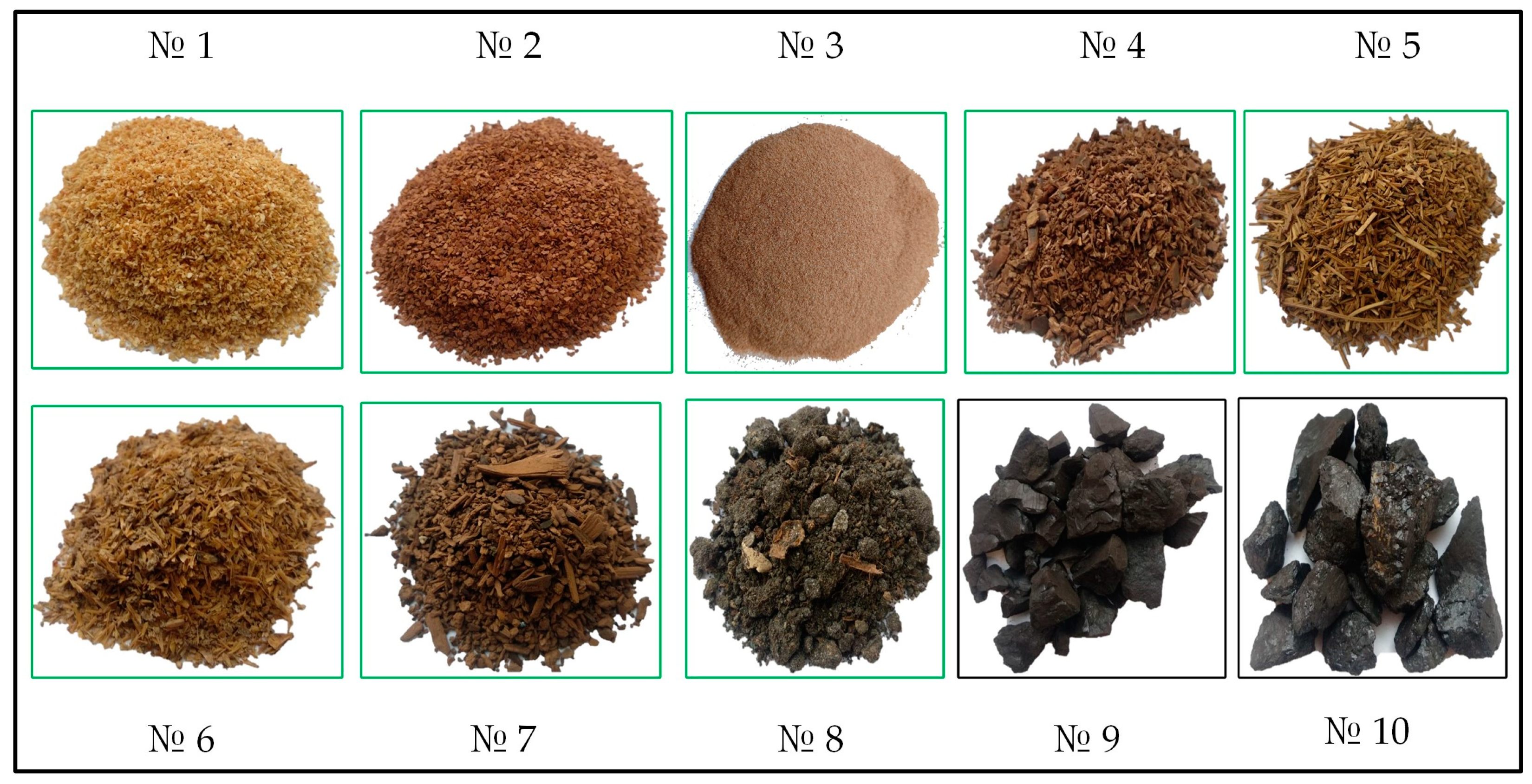
2.1. Fuels

The following biomass wastes and coals sampled in Krasnoyarsk, Russia were used as fuels (Table 1):
Larch sawdust, larch bark, birch sawdust, pinecones and cedar needles are among the most common and accessible types of waste from the wood-processing industry. Brewer’s spent grain and hydrolysis lignin are food-processing wastes. Sewage sludge is a problem for every city because if the city does not organize its utilization, it is exported to specialized sludge fields, the area of which increases every year and poses a certain ecological threat to the environment. For comparison, we studied two coals used as fuel for thermal power generation in different areas of the Russian Federation. Bolshesyrskiy brown coal was studied as lignite coal, and Kaa-hem bituminous coal was studied as bituminous coal.
A visualization of the fuels under study is presented in Figure 1.
Fuels with particle sizes of 100–200 µm were studied; this corresponds to the size of coal particles during flame combustion in boiler furnaces. For this purpose, the fuels were ground in a Retsch DM200 mill (Haan, Germany), and then, the Retsch AS200 analytical sieving machine (Germany) with a sieve with mesh size 100–200 µm was used (in accordance with ISO 3310-1:2016 [36]).
The methods described in detail in the following standards were used to determine the main thermal characteristics of the tested fuels: ISO 562:2010; ISO 11722:2013; ISO 1171:2024; ISO 1928:2020; ASTM D5373-14e1 [37,38,39,40,41]. To determine moisture content, the MA-150 moisture analyzer (Sartorius, Göttingen, Germany) was used; ash content and volatile matter content were determined using a Snol 7.2/1300 muffle furnace (AB “Umega”, Lithuania); carbon, hydrogen, sulfur and nitrogen were determined using a Vario MACRO cube elemental analyzer (Elementar Analysensysteme GmbH, Langenselbold, Germany); higher heat of combustion was determined using a C6000 calorimeter (IKA, Staufen, Germany). Oxygen was determined by the subtraction method. The results of the thermotechnical analysis are presented in Table 2.
The highest moisture content was observed in brewer’s spent grain (59.4%), hydrolysis lignin (47.5%) and sewage sludge (35.7) (Table 2). High moisture content affects the reduction of the lower heating value in the working condition. Therefore, these fuels should be dried to the lowest possible moisture content before use. The highest ash content is characteristic for sewage sludge (62.3%), which also affects the reduction of combustion heat. The heat of combustion of all the studied fuels is high enough, because it is presented in dry, ashless state. In reality, these values will be less, depending on the content of moisture and ash in the fuel. The highest heat of combustion is characteristic for coals No. 9 and No. 10, as well as the highest carbon content. When forming solid fuel mixtures, it is necessary to take into account that when adding biomass waste to coals, the heat of combustion will decrease, which may negatively affect the technical and economic performance of the boiler house.

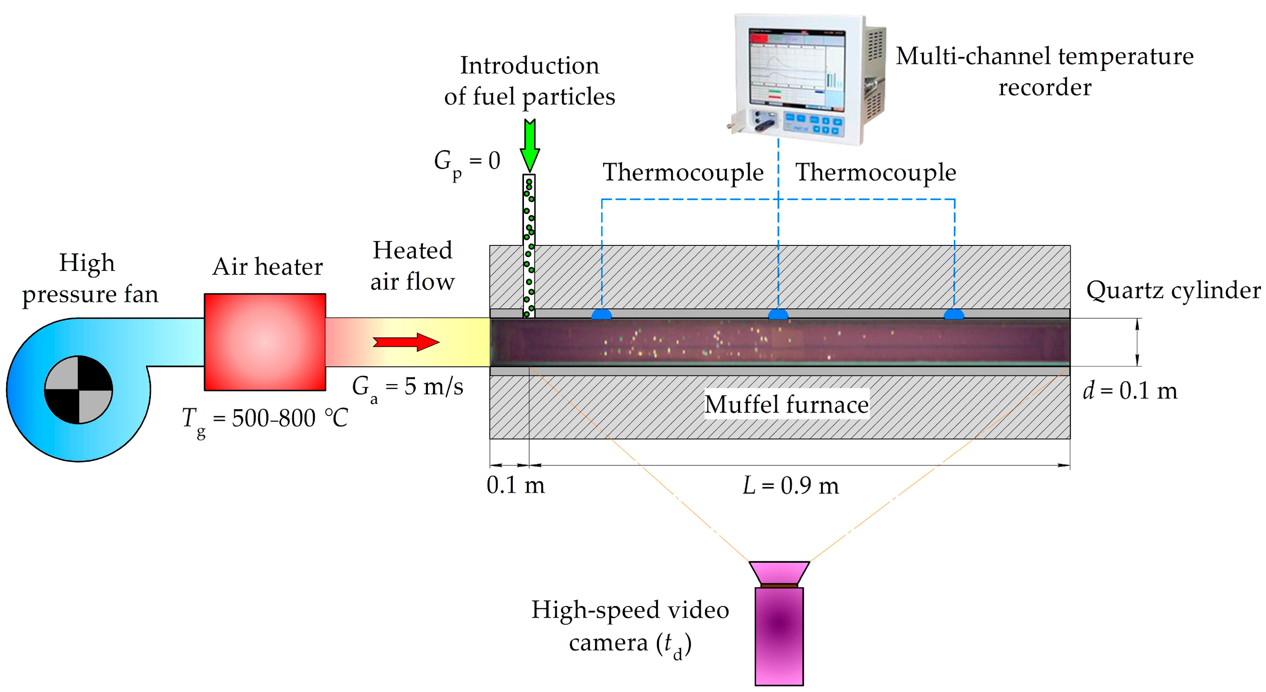
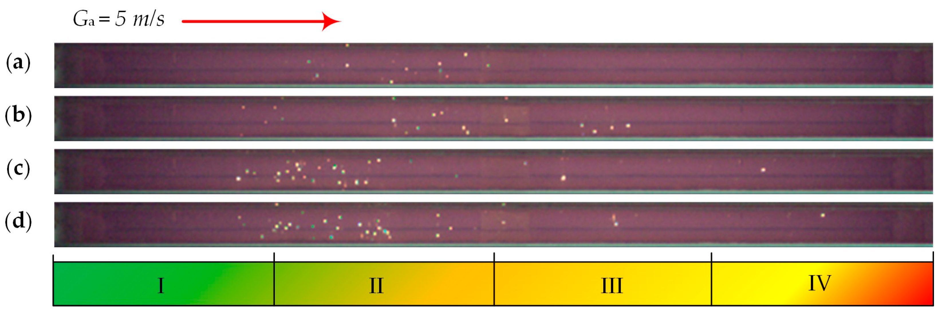
2.2. Methodology of Experiments on the Firing Bench

Experiments on combustion of fuels in hot air flow were carried out on a fire bench, the scheme of which is shown in Figure 2, according to the approved methodology [42,43].
The fire bench includes the following devices: ROBUST gas (air) blower (LEISTER, Germany) with the following characteristics: power of 0.25 kW, maximum air flow of 1200 L/min, maximum static pressure of 8 kPa; LEISTER LE 5000 HT gas heater (LEISTER, Germany) with the following characteristics: power of 11 kW, maximum inlet air temperature of 100 °C, maximum outlet air temperature of 900 °C, minimum air flow rate of 635 L/min; reactor consisting of a muffle furnace in the form of a General Therm RT 1000.1100 SP tube (Nevaterm, Russia) with the following characteristics: power of 13 kW and quartz cylinder with length of 1 m and inner diameter 0.1 m, working heated length of 0.9 m with maximum temperature not exceeding 800 °C (Figure 2).
The fire bench works as follows (Figure 2): the gas-air flow at a speed of 5 m/s is fed by the air blower through the gas heater (where it is heated to a given temperature) into the reactor, which maintains a given temperature in the range from 20 to 800 °C along the entire length of the quartz tube due to the lack of heat loss through the walls of the reactor. Four thermocouples were used to register the temperature of the gas-air flow before entering the reactor, in the middle of the reactor and at its outlet (the range of measured temperatures is 0–1100 °C, the accuracy in measuring temperatures over 400 °C is ±0.004 T and the inertia is less than 3 s). The readings of thermocouples were also used to adjust the temperature of the oxidizer flow. The limits of acceptable basic reduced error ±0.25% (Figure 2) data coming from thermocouples were recorded with the help of a PMT-59 multi-channel recorder (Elemer, Moscow, Russia) with the following characteristics: 12 measuring channels, polling cycle of all channels less than 1 s, the range of measured temperatures from −50 to 1100 °C (when connecting thermocouples with nominal static characteristic of XA), accuracy class A.
To cool the gas-air flow and flue gases to 150 °C, a gas cooler (working together with a General Therm RT 1000.1100 SP tube muffle furnace (Nevaterm, Saint Petersburg, Russia)) was used; flue gases were removed by means of a gas removal system. The gas recirculation system serves to increase the efficiency of the fire stand by removing heat from the gas-air flow and supplying it with a temperature not exceeding 100 °C to the inlet of the gas blower.
Fuel with a mass of ±5 mg was introduced into the gas-air stream using an automated device through a 6 mm diameter ceramic tube passing through the top cover of the reactor (Figure 2) and a corresponding hole in the wall of the quartz cylinder. The process of ignition and combustion of fuel particles occurring in the gas-air flow (inside the quartz cylinder with a length of 0.9 m) was recorded through the viewing slit of reactor 4 (Figure 2) by a Phantom V411 color high-speed video camera (Vision Research, USA) with the following characteristics: shooting speed of 4000 frames per second at a resolution of 1008 × 56 pixels, image depth of 12 bits, matrix pixel size of 20 μm, minimum exposure time of 1 μs. Distagon 1.4/35 ZF.2 T* wide-angle lens (Carl Zeiss, Germany) with the following characteristics was used together with the video camera: aperture at minimum focal length of 1.4, minimum focal length of 35 mm. The video camera was positioned perpendicular to the reactor at a distance of 2 m from the viewing slit.
Video recordings were processed automatically using Phantom Camera Control software (https://www.phantomhighspeed.com/resourcesandsupport/phantomresources/pccsoftware, Vision Research, Wayne, NJ, USA). Color video recordings of the experiments were converted to monochrome format and sequentially processed. For each frame, gray shades (from 0 to 4095—from black to white, respectively) in each point (pixel) were analyzed separately. For the process of fuel combustion in black and white colors, the luminescence interval of 3520–4095 corresponded. Fuel ignition was recorded automatically at the value of 3520 in shades of gray at any point in the area of video registration. In turn, this allowed us to determine the coordinate of the plane perpendicular to the direction of gas-air flow in which the fuel particle was ignited. The systematic and random errors in determining the ignition delay time (td) did not exceed 0.5% and 15%, respectively.
In order to minimize errors, between 4 and 9 experiments were performed for each fuel at the following temperature (Tg) values: 500, 550, 550, 600, 650, 650, 700, 750 and 800 °C with video recording from the point where the fuel enters the reactor to its end along the flow direction. This length (L) was 0.9 m, and the total length of the reactor was 1 m (Figure 2). This distance was traveled by the fuel particles from the cross-sectional plane of the quartz cylinder with the coordinate x = 0, where they were introduced into the air stream, to its exit cross-section x = L
It is impossible to reliably establish td by dividing the value of the set coordinate by the instantaneous value of the velocity of fuel particles in the gas-air flow due to the fact that particles with different sizes from 100 to 200 microns came with an initial velocity (Gp) in the gas-air flow equal to zero; the velocity of the gas-air flow (Ga) was 5 m/s and was constant along the entire length of the reactor 4. With increasing velocity, the particles accelerate from Gp = 0 to Gp = Ga, and their values differ for fuel particles of different sizes and densities.
To determine the ignition delay time, an approximation expression td = f(x) was derived for solid particles of 100–200 μm in size. It was assumed that solid particles with density ρp of spherical shape (sizes corresponded to the average sizes of the specified range Dp = 150 μm) were introduced with initial velocity Gp = 0 into a horizontal gas-air flow at Ga = 5 m/s, ρa = 0.383 kg/m3, µa = 40.5·10−6 Pa-s. Average values of density and dynamic viscosity of air in the temperature range of 500–800 °C were used, since their values in this range vary by less than 20% and 30%. After introduction of the fuel portion into the air stream, the volumetric concentration of particles under the conditions of their motion in a cylindrical tube with a diameter of 0.1 m was less than 0.02 unit/m3 (sparse disperse system). Therefore, when solving the formulated problem, we considered the motion of a single particle whose characteristics do not depend on neighboring particles. Within the framework of the simplified approach used, the influence of dynamic and thermal lag of particles on the characteristics of the airflow was not taken into account. It was assumed that only the drag force (the carrying force of the air flow) acts on the particle. The effect of gravity was not taken into account, since the analysis of videograms registered a rectilinear motion of particles in the horizontal direction [44].
It was found that at the above-mentioned initial data point, the flow regime of particles of different sizes in the air flow is characteristic of the transition region, since Re = 7.09 (the intermediate flow regime of a dispersed phase particle is realized in the range of Reynolds numbers Re = 0.015–700). Under such conditions, the dependence of the dimensionless particle velocity on the dimensionless time was obtained from the expression (1) [45]:
ν = 1 6 6 R e 1 + 6 R e 1 ν 0 2 3 exp τ 1 3 2
where ν is dimensionless velocity; Re is Reynolds number; ν0 is initial dimensionless velocity; τ is dimensionless time; ρa is air density, kg/m3; Ga is velocity of gas-air flow, m/s; Dp is particle diameter, µm; µa is dynamic viscosity of air, Pa·s; ρp is particle density, kg/m3; and Gp is particle velocity, m/s.
Reynolds number was found from expression (2):
R e = ρ a G a D p μ a ,
where ρa is air density, kg/m3; Ga is velocity of gas-air flow, m/s; Dp is particle diameter, µm; and µa is dynamic viscosity of air, Pa·s.
The value of dimensionless time was found from the expression (3):
τ = 12 μ a ρ p G p 2 t
where ρp is particle density, kg/m3; Gp is particle velocity, m/s; and t is time, s.
The value of dimensionless velocity was found from the expression (4):
ν = G p G a ,
where ν is dimensionless velocity; Ga is gas-air flow velocity, m/s; and Gp is particle velocity, m/s.
Thus, based on the abovementioned expressions, the larger the particle size and density, the more time and distance (which is limited by the reactor design with a length of 0.9 m) are required for their velocity to increase to the Ga value, which corresponds to the results of the study and real conditions of aerodynamic processes in boiler furnaces during flaring combustion of solid natural fuel [42,43]. Under such conditions in the experiments, the velocity of particles with higher density (coal ρp = 800 kg/m3) will be lower compared to particles of lower density (biomass ρp = 540 kg/m3) at L = 0.9 m, Dp = 150 μm and other identical conditions.

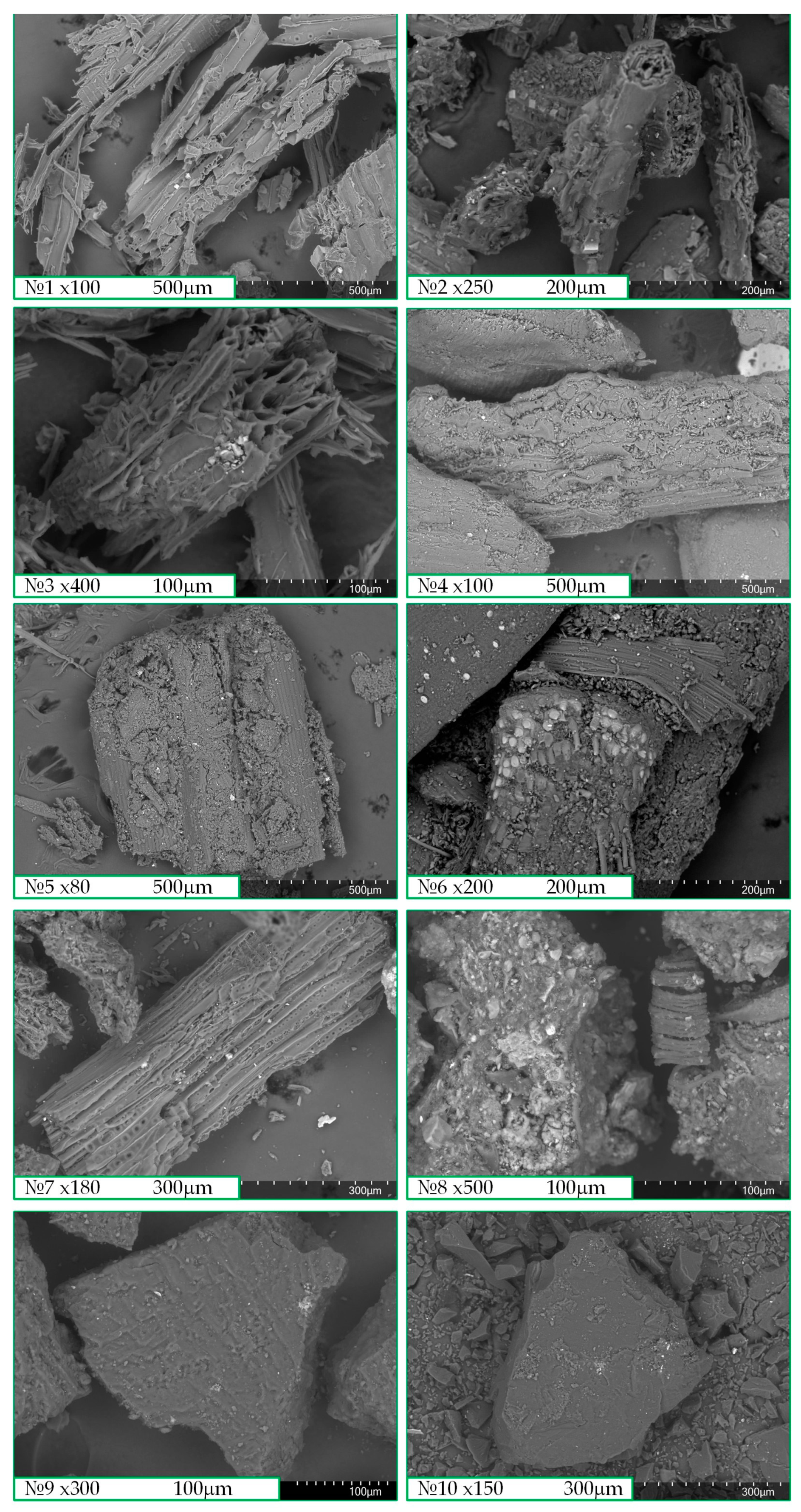
2.3. Analysis of Fuel Particle Surface

During convective heating, the specific surface volume of fuel particles plays an important role. For qualitative assessment of the fuel particle surface for the presence of pores, cracks or channels, the presence of which increases the specific volume of particle surfaces, the TM-400 (Hitachi, Japan) scanning electron microscope (SEM) was used. It obtains a finished image using electromagnetic coils that form a finely focused beam of electrons that are sequentially emitted and received from the entire area of the substrate. The main characteristics of the microscope were the following: magnification from ×10 to ×100,000 times; depth of field of 0.5 mm; accelerating voltage from 5 kV to 15 kV; maximum sample size up to 80 mm in diameter and up to 50 mm in height; minimum displacement step of 65 nm. The TM-4000 microscope is equipped with a microanalysis system for Hitachi TM4000Plus benchtop microscope, including the following characteristics: silicon-drift detector with a working area of 30 mm2; guaranteed energy resolution of 137 eV (Mn Ka); electron source that is a pre-centered tungsten cathode. The main function of the TM-4000 microscope is to obtain and process magnified images of the sample surface in backscattered electrons (BSEs) and secondary electrons (SEs). Figure 3 shows scanning electron microscopy (SEM) images of fuels № 1–10; the deciphering of fuel names is presented in Section 2.1.
The surface of biomass particles has a large number of pores, cracks and channels due to its structure. This, in turn, increases its reactivity, as the oxidizer penetrates more quickly through the holes inside the particle itself and reacts with carbon, thereby accelerating the physical–chemical combustion process. Biomass particles have different geometric shapes; mostly, they are elongated in contrast to coal particles, which mostly have a geometric shape in the form of a sphere. There are no pores, cracks and channels of large sizes on the surface of coal particles, especially in bituminous coal (Figure 3).

3. Results and Discussion

The conditions of the experiment on the fire bench correspond to the conditions of flaring combustion of solid natural fuel in boilers equipped with chamber furnaces. Figure 4, Figure 5, Figure 6, Figure 7, Figure 8, Figure 9, Figure 10, Figure 11, Figure 12, Figure 13, Figure 14 and Figure 15 show the frames of videograms of the ignition of biomass, coal and their mixtures. Bright yellow dots in Figure 3, Figure 4, Figure 5, Figure 6, Figure 7, Figure 8, Figure 9, Figure 10, Figure 11, Figure 12, Figure 13 and Figure 14 show the dynamics of ignition development and combustion of fuel particles under conditions of convective heating created by the gas-air flow heated up to 700 °C with the velocity Ga = 5 m/s (the flow direction is indicated by the red arrow). Letters (a), (b), (c) and (d) show the frames with the interval ∆t = 0.01 s from the beginning of their ignition (Figure 4a); the mass of the fuels was about 5 g (it is about 100 particles of 100–200 μm size).
The length of the image corresponding to the length of the reactor slit through which the video was taken is conditionally divided into four equal areas (I–IV). Fuel particles enter the gas-air stream in region I, where their ignition occurs, and for some fuels, most of the particles do not have time to ignite even after reaching region IV. Figure 4 shows the frames of the videogram of larch sawdust ignition.
The ignition of larch sawdust occurs in area II; as ∆t increases, ignition shifts to area I (Figure 4). The main combustion of the particles occurs in area II. A small fraction of larch sawdust is ignited in areas III and IV, indicating the high combustibility of this woody biomass. The whole process affects all areas, I–IV.
Figure 5 shows the ignition and combustion of larch bark particles. Particle ignition occurs in area I, and the main combustion affects two areas, I and II. The remaining particles finish burning in region III and IV. It can be noted that the intensity of particle ignition is high.
The birch sawdust particles show high ignition intensity. Most of the birch sawdust burns in area I, the remainder burns in area II and a few particles manage to reach area III (Figure 6).
Ignition of pinecones occurs in area I, and the main burning of particles occurs in areas II and III. This is due to their high intensity of ignition. Parts of the particles are ignited in area IV (Figure 7). From the large number of bright spots in Figure 7, it can be concluded that most of the particles are burned, unlike the biomass presented in Figure 4, Figure 5 and Figure 6.
The ignition of cedar needles occurs in area I. The bulk of the particles are ignited in area II, and a small part are ignited in areas III and IV (Figure 8). A high helicity of ignition and combustion of particles is observed which, as in Figure 7, is due to the ignition of most of the fuel particles.
Brewer’s spent grain particles with a small composition ignited in areas II and III; the bulk did not ignite (Figure 9).
The bulk of hydrolyzed lignin particles are ignited in the second area, with a small amount in the first area and the third area (Figure 10). According to the abundance of ignited particles, hydrolyzed lignin shows its high combustion characteristics compared to brewer’s spent grain.
The sewage sludge particles are ignited in area I and II, showing the high ignition intensity of most particles. A part of the particles manages to reach and ignite in area III (Figure 11). High combustion helicity, as for hydrolyzed lignin and for cedar and pinecone needles, is not observed.
A small fraction of lignite coal ignites in area I, the main physicochemical processes extend into areas II and III and a small fraction of coal particles ignite in area IV. In general, this type of coal is quite highly reactive. This is due to the display of a large number of bright dots in Figure 12, demonstrating the combustion of coal particles.
At 700 °C, several particles of bituminous coal in area II are ignited (Figure 13). Higher temperature conditions are required for this coal. The bulk of the coal did not ignite and flew into the ventilation system.
Adding 50% of brewer’s spent grain to coal worsens the ignition and combustion process of the mixture. Analyzing Figure 14, we can see that most of the coal and biomass particles are ignited in areas III and IV. In area I, fuel particles are not ignited, although in Figure 12, we can observe quite a different picture.
The addition of 50% hydrolyzed lignin to coal, judging from the videogram image, does not worsen the combustion process; fuel particles burn in areas II and III (Figure 15). Ignition of fuel particles is also observed in area I.
The dependence of the ignition time delay on the heating temperature of the air stream of individual fuels is shown in Figure 16.
Bituminous coal has the highest td values (0.063–0.197 s). Its ignition occurs in the higher temperature region at 600 °C, in contrast to lignite coal, whose td values ranged from 0.031 to 0.194 s. The particles of lignite coal ignited at 500 °C (Figure 16). Figure 16a shows the td values of woody biomass and coal. Of the studied woody biomass, the lowest td values were for cedar needles (0.007–0.091 s), and the highest were for larch sawdust (0.022–0.165 s).
Figure 16b shows the td values of food waste, sewage sludge, and for comparison, the td values of coals are presented. Brewer’s spent grain has the highest td values (0.045–0.145 s) due to its high moisture content of 59.4% (Figure 16b, Table 2). This affected the ignition temperature conditions of the fuel particles, which ignited at only 600 °C, as did bituminous coal. Hydrolyzed lignin has a lower td value (0.010–0.100 s) than sewage sludge and BSG; this is explained by the fact that in the process of preparation for combustion (during grinding of hydrolyzed lignin), the value of total moisture was reduced. Some researchers have emphasized in their works the feasibility of using BSG as a supplementary fuel to coal and biomass [29,30,31]. Hydrolysis lignin, sewage sludge and BSG were obtained with high moisture content, since these wastes were stored for a long time in the open air and, due to their increased hydrophilic properties, absorbed moisture. In the process of preparing the fuels for combustion, the fuels reached an air-dry state while inside the laboratory, and the moisture content of hydrolyzed lignin and sewage sludge decreased significantly compared to the initial value of the moisture content, so they showed low values of ignition time delay in contrast to BSG. It can be concluded that the rate of moisture content reduction in BSG is low, which should be taken into account in the practical application of this type of biomass as an energy fuel.
Figure 16c shows the comparison of td values of sewage sludge and birch sawdust; their values are almost identical, which indicates the high reactivity of sewage sludge, even under the condition of high ash content (Table 2). Figure 16d shows the comparison of td values of all individual fuels investigated in this work. We would like to note the low td values of hydrolyzed lignin compared to woody biomass; among all studied fuels, hydrolyzed lignin is in second place, in terms of the lowest td values, after cedar needles, as shown in Figure 16d, which makes it a promising, highly reactive additive fuel to coal.
Figure 17 shows the ignition time delay values of the solid fuel mixtures.
The addition of brewer’s spent grain increases the td value that makes the mixtures less reactive compared to lignite coal (Figure 17a). Increasing the mass fraction of biomass in the mixture in steps of 25% at an air flows temperature of 800 °C, the td value will increase from 0.034 to 0.039 s compared to a 0.031 s increase for coal. As the mass fraction of biomass increases, the heat of combustion of the mixture will decrease. To improve reactivity, it is necessary to carry out pre-drying of brewer’s spent grain.
When hydrolyzed lignin is added to coal (Figure 17b), the td value decreases from 0.022 to 0. 017 s at an airflow temperature of 800 °C. Hydrolyzed lignin has shown itself as a highly reactive fuel. Its addition to coal is promising.

4. Conclusions

In this work, the ignition and combustion of different biomass wastes, two coals of different degrees of metamorphism and two mixtures based on coal and biomass wastes with particle sizes of 100–200 μm, under convective heat exchange conditions in a flow of heated air with a velocity of 5 m/s at temperatures from 500 to 800 °C were investigated. Cedar needles have the lowest value of ignition time delay (td) compared to coals: at 500 °C, it is two times lower than that of lignite coal, and at 800 °C it is four times lower. For bituminous coal, it is 5 times lower at 600 °C and nine times lower at 800 °C. The second lowest td value among all the studied fuels was that of hydrolyzed lignin, which makes it a promising supplementary fuel to coal. The td values of sewage sludge are on par with birch sawdust, but for energy utilization of these wastes, it is necessary to reduce the ash content, thus increasing the calorific value of sewage sludge.
The qualitative surface analysis of all individual fuels showed that, except for coals, all fuels have a large number of pores, cracks and channels, which means that they have a high specific surface area of particles.
The addition of wet brewer’s spent grain negatively affected the td values of the blends, while the addition of hydrolyzed lignin to lignite coal conversely decreased the ignition delay time values, making the fuel blend highly reactive compared to coal. During the energy utilization of BSG, it is necessary to take into account its slow speed in reaching an air-dry state; therefore, it is expedient to use special drying devices for this purpose. Wood, hydrolyzed lignin and sewage sludge, in the process of their delivery to the fuel storage and storage in the open air, will lose part of their moisture, but it is also advisable to dry them before combustion in power plants.
Adding biomass to coal improves not only the reaction properties of the mixture compared to coal but also the environmental performance by reducing the content of CO2, SOx and total ash in flue gases.

Author Contributions

Conceptualization, A.Z., N.Z. and S.C.; methodology, S.C.; software, S.C.; validation, S.C. and A.Z.; formal analysis, I.G.; investigation, N.Z.; resources, A.Z.; data curation, A.Z.; writing—original draft preparation, A.Z.; writing—review and editing, N.Z., A.Z. and I.G.; visualization, S.C.; supervision, A.Z.; project administration, A.Z. All authors have read and agreed to the published version of the manuscript.

Funding

This research was supported by the Russian Science Foundation [grant number 23-23-00280. URL (accessed on 16 June 2024): https://rscf.ru/project/23-23-00280/].

Institutional Review Board Statement

Not applicable.

Informed Consent Statement

Not applicable.

Data Availability Statement

The data presented in this study are available on request from the corresponding author. The data are not publicly available due to confidentiality reasons.

Conflicts of Interest

The authors declare no conflicts of interest.

Nomenclature

Adash in a dry state (%)
Cdaf, Hdaf, Ndaf, Odaf, Sdaffraction of carbon, hydrogen, nitrogen, oxygen and sulfur converted to a dry, ash-free state (%)
Dpparticle diameter (micron)
Gagas-air flow velocity (m/s)
Gpfuel particle velocity (m/s)
HHVhigher heating value (MJ/kg)
Llength (m)
MCmoisture content (%)
ReReynolds number
Tgheated air temperature (°C)
ttime (s)
tdignition delay time (s)
Δttime step (s)
VCdafvolatile content converted to a dry, ash-free state (%)
ρaair density (kg/m3)
ρpparticle density (kg/m3)
µadynamic viscosity of air (Pa·s)
νdimensionless velocity
ν0initial dimensionless velocity
τnon-dimensional time

References

  1. Qiang, G.; Tang, S.; Hao, J.; Di Sarno, L.; Wu, G.; Ren, S. Building automation systems for energy and comfort management in green buildings: A critical review and future directions. Renew. Sustain. Energy Rev. 2023, 179, 113301. [Google Scholar] [CrossRef]
  2. Wang, W.; Yang, H.; Xiang, C. Green roofs and facades with integrated photovoltaic system for zero energy eco-friendly building—A review. Sustain. Energy Technol. Assess. 2023, 60, 103426. [Google Scholar] [CrossRef]
  3. Chicherin, S.; Zhuikov, A.; Junussova, L. Factors Affecting Indoor Temperature in the Case of District Heating. Sustainability 2023, 15, 15603. [Google Scholar] [CrossRef]
  4. Dang, L.M.; Nguyen, L.Q.; Nam, J.; Nguyen, T.N.; Lee, S.; Song, H.-K.; Moon, H. Fifth generation district heating and cooling: A comprehensive survey. Energy Rep. 2024, 11, 1723–1741. [Google Scholar] [CrossRef]
  5. Chicherin, S.; Zhuikov, A.; Junussova, L. Integrating a heat pump into a 4th generation district heating (4GDH) system—Two-mode configuration inputting operational data. Energy Build. 2022, 275, 112445. [Google Scholar] [CrossRef]
  6. Sorknæs, P.; Østergaard, P.A.; Thellufsen, J.Z.; Lund, H.; Nielsen, S.; Djørup, S.; Sperling, K. The benefits of 4th generation district heating in a 100% renewable energy system. Energy 2020, 213, 119030. [Google Scholar] [CrossRef]
  7. Malinauskaite, J.; Jouhara, H.; Czajczyńska, D.; Stanchev, P.; Katsou, E.; Rostkowski, P.; Thorne, R.J.; Colón, J.; Ponsá, S.; Al-Mansour, F.; et al. Municipal solid waste management and waste-to-energy in the context of a circular economy and energy recycling in Europe. Energy 2017, 141, 2013–2044. [Google Scholar] [CrossRef]
  8. Ahrenfeldt, J.; Thomsen, T.P.; Henriksen, U.; Clausen, L.R. Biomass gasification cogeneration—A review of state of the art technology and near future perspectives. Appl. Therm. Eng. 2013, 50, 1407–1417. [Google Scholar] [CrossRef]
  9. Shah, A.V.; Srivastava, V.K.; Mohanty, S.S.; Varjani, S. Municipal solid waste as a sustainable resource for energy production: State-of-the-art review. J. Environ. Chem. Eng. 2021, 9, 105717. [Google Scholar] [CrossRef]
  10. Biancini, G.; Cioccolanti, L.; Moradi, R.; Moglie, M. Comparative study of steam, organic Rankine cycle and supercritical CO2 power plants integrated with residual municipal solid waste gasification for district heating and cooling. Appl. Therm. Eng. 2024, 241, 122437. [Google Scholar] [CrossRef]
  11. Tang, C.; Pan, W.; Zhang, J.; Wang, W.; Sun, X. A comprehensive review on efficient utilization methods of High-alkali coals combustion in boilers. Fuel 2022, 316, 123269. [Google Scholar] [CrossRef]
  12. Kumar, V.; Saxena, V.K.; Kumar, R.; Kumar, S. Energy, exergy, sustainability and environmental emission analysis of coal-fired thermal power plant. Ain Shams Eng. J. 2024, 15, 102416. [Google Scholar] [CrossRef]
  13. Vig, N.; Ravindra, K.; Mor, S. Environmental impacts of Indian coal thermal power plants and associated human health risk to the nearby residential communities: A potential review. Chemosphere 2023, 341, 140103. [Google Scholar] [CrossRef] [PubMed]
  14. Ma, L.; Goldfarb, J.L.; Song, J.; Chang, C.; Ma, Q. Enhancing cleaner biomass-coal co-combustion by pretreatment of wheat straw via washing versus hydrothermal carbonization. J. Clean. Prod. 2022, 366, 132991. [Google Scholar] [CrossRef]
  15. Wang, X.; Xu, J.; Ling, P.; An, X.; Han, H.; Chen, Y.; Jiang, L.; Wang, Y.; Su, S.; Hu, S.; et al. A study on the release characteristics and formation mechanism of SO2 during co-combustion of sewage sludge and coal slime. Fuel 2023, 333, 126511. [Google Scholar] [CrossRef]
  16. Sahu, S.G.; Chakraborty, N.; Sarkar, P. Coal-biomass co-combustion: An overview. Renew. Sustain. Energy Rev. 2014, 39, 575–586. [Google Scholar] [CrossRef]
  17. Wang, Y.; Qin, Y.; Vassilev, S.V.; He, C.; Vassileva, C.G.; Wei, Y. Migration behavior of chlorine and sulfur during gasification and combustion of biomass and coal. Biomass Bioenergy 2024, 182, 107080. [Google Scholar] [CrossRef]
  18. Liu, L.; Memon, M.Z.; Xie, Y.; Gao, S.; Guo, Y.; Dong, J.; Gao, Y.; Li, A.; Ji, G. Recent advances of research in coal and biomass co-firing for electricity and heat generation. Circ. Econ. 2023, 2, 100063. [Google Scholar] [CrossRef]
  19. Yang, W.; Pudasainee, D.; Gupta, R.; Li, W.; Wang, B.; Sun, L. An overview of inorganic particulate matter emission from coal/biomass/MSW combustion: Sampling and measurement, formation, distribution, inorganic composition and influencing factors. Fuel Process. Technol. 2021, 213, 106657. [Google Scholar] [CrossRef]
  20. Verma, M.; Loha, C.; Sinha, A.N.; Chatterjee, P.K. Drying of biomass for utilising in co-firing with coal and its impact on environment—A review. Renew. Sustain. Energy Rev. 2017, 71, 732–741. [Google Scholar] [CrossRef]
  21. Sami, M.; Annamalai, K.; Wooldridge, M. Co-firing of coal and biomass fuel blends. Prog. Energy Combust. Sci. 2001, 27, 171–214. [Google Scholar] [CrossRef]
  22. Agbor, E.; Zhang, X.; Kumar, A. A review of biomass co-firing in North America. Renew. Sustain. Energy Rev. 2014, 40, 930–943. [Google Scholar] [CrossRef]
  23. Glushkov, D.O.; Matiushenko, A.I.; Nurpeiis, A.E.; Zhuikov, A.V. An experimental investigation into the fuel oil-free start-up of a coal-fired boiler by the main solid fossil fuel with additives of brown coal, biomass and charcoal for ignition enhancement. Fuel Process. Technol. 2021, 223, 106986. [Google Scholar] [CrossRef]
  24. Dubinin, Y.V.; Yazykov, N.A.; Yeletsky, P.M.; Tabakaev, R.B.; Belyanovskaya, A.I.; Yakovlev, V.A. Catalytic co-combustion of biomass and brown coal in a fluidized bed: Economic and environmental benefits. China Environ. Sci. 2024, 140, 24–36. [Google Scholar] [CrossRef] [PubMed]
  25. Jeong, Y.; Kim, J.-S.; Lee, Y.-E.; Shin, D.-C.; Ahn, K.-H.; Jung, J.; Kim, K.-H.; Ku, M.-J.; Kim, S.-M.; Jeon, C.-H.; et al. Investigation and Optimization of Co-Combustion Efficiency of Food Waste Biochar and Coal. Sustainability 2023, 15, 14596. [Google Scholar] [CrossRef]
  26. Jaworski, T.J.; Kajda-Szcześniak, M. Study on the Similarity of the Parameters of Biomass and Solid Waste Fuel Combustion for the Needs of Thermal Power Engineering. Sustainability 2020, 12, 7894. [Google Scholar] [CrossRef]
  27. Ashraf, A.; Sattar, H.; Munir, S. A comparative performance evaluation of co-combustion of coal and biomass in drop tube furnace. J. Energy Inst. 2022, 100, 55–65. [Google Scholar] [CrossRef]
  28. Schönnenbeck, C.; Maryandyshev, P.; Trouvé, G.; Brillard, A.; Lyubov, V.; Brilhac, J.-F. Combustion of hydrolysis lignin in a drop tube furnace and subsequent gaseous and particulate emissions. Bioresour. Technol. 2019, 288, 121498. [Google Scholar] [CrossRef] [PubMed]
  29. Celaya, A.M.; Lade, A.T.; Goldfarb, J.L. Co-combustion of brewer’s spent grains and Illinois No. 6 coal: Impact of blend ratio on pyrolysis and oxidation behavior. Fuel Process. Technol. 2015, 129, 39–51. [Google Scholar] [CrossRef]
  30. Castro, L.E.N.; Sganzerla, W.G.; Matheus, L.R.; Mançano, R.R.; Ferreira, V.C.; Barroso, T.L.C.T.; da Rosa, R.G.; Colpini, L.M.S. Application of brewers’ spent grains as an alternative biomass for renewable energy generation in a boiler combustion process. Sustain. Chem. Environ. 2023, 4, 100039. [Google Scholar] [CrossRef]
  31. Vasileiadou, A. Energy recovery from brewers’ spent grain combustion/co-combustion with lignite. Int. J. Environ. Sci. Technol. 2024, 21, 5335–5350. [Google Scholar] [CrossRef]
  32. Batistella, L.; Silva, V.; Suzin, R.C.; Virmond, E.; Althoff, C.A.; Moreira, R.F.P.M.; José, H.J. Gaseous emissions from sewage sludge combustion in a moving bed combustor. Waste Manag. 2015, 46, 430–439. [Google Scholar] [CrossRef]
  33. Liang, Y.; Xu, D.; Feng, P.; Hao, B.; Guo, Y.; Wang, S. Municipal sewage sludge incineration and its air pollution control. J. Clean. Prod. 2021, 295, 126456. [Google Scholar] [CrossRef]
  34. Strandberg, A.; Thyrel, M.; Falk, J.; Öhman, M.; Skoglund, N. Morphology and phosphate distribution in bottom ash particles from fixed-bed co-combustion of sewage sludge and two agricultural residues. Waste Manag. 2024, 177, 56–65. [Google Scholar] [CrossRef]
  35. Sever Akdağ, A.; Atak, O.; Atimtay, A.T.; Sanin, F.D. Co-combustion of sewage sludge from different treatment processes and a lignite coal in a laboratory scale combustor. Energy 2018, 158, 417–426. [Google Scholar] [CrossRef]
  36. ISO 3310-1:2016; Test Sieves—Technical Requirements and Testing. ISO: Geneva, Switzerland, 2016.
  37. ISO 562:2010; Hard Coal and Coke—Determination of Volatile Matter. ISO: Geneva, Switzerland, 2010.
  38. ISO 11722:2013; Solid Mineral Fuels—Hard Coal—Determination of Moisture in the General Analysis Test Sample by Drying in Nitrogen. ISO: Geneva, Switzerland, 2013.
  39. ISO 1171:2024; Solid Mineral Fuels—Determination of Ash. ISO: Geneva, Switzerland, 2024.
  40. ISO 1928:2020; Solid Mineral Fuels—Determination of Gross Calorific Value by the Bomb Calorimetric Method and Calculation of Net Calorific Value. ISO: Geneva, Switzerland, 2024.
  41. ASTM D5373-14e1; Standard Test Methods for Determination of Carbon, Hydrogen and Nitrogen in Analysis Samples of Coal and Carbon in Analysis Samples of Coal and Coke Significance and Use. ASTM: West Conshohocken, PA, USA, 2016.
  42. Hannl, T.K.; Skoglund, N.; Priščák, J.; Öhman, M.; Kuba, M. Bubbling fluidized bed co-combustion and co-gasification of sewage sludge with agricultural residues with a focus on the fate of phosphorus. Fuel 2024, 357, 129822. [Google Scholar] [CrossRef]
  43. Gu, T.; Ma, W.; Guo, Z.; Berning, T.; Yin, C. Stable and clean co-combustion of municipal sewage sludge with solid wastes in a grate boiler: A modeling-based feasibility study. Fuel 2022, 328, 125237. [Google Scholar] [CrossRef]
  44. Glushkov, D.; Zhuikov, A.; Zemlyansky, N.; Pleshko, A.; Fetisova, O.; Kuznetsov, P. Influence of the Composition and Particle Sizes of the Fuel Mixture of Coal and Biomass on the Ignition and Combustion Characteristics. Appl. Sci. 2023, 13, 11060. [Google Scholar] [CrossRef]
  45. Arkhipov, V.A.; Boiko, V.M.; Goldin, V.D.; Maslov, E.A.; Orlov, S.E.; Poplavskiy, S.V.; Usanina, A.S.; Zharova, I.K. Mathematical modelling of the liquid atomization process by cocurrent gas flow. IOP Conf. Ser. Mater. Sci. Eng. 2016, 124, 012076. [Google Scholar] [CrossRef]
Figure 1. Appearance of the tested fuels (No 1—larch sawdust; No 2—larch bark; No 3—birch sawdust; No 4—pinecones; No 5—cedar needles; No 6—brewer’s spent grain; No 7—hydrolysis lignin; No 8—sewage sludge; No 9—lignite coal; No 10—bituminous coal).
Sustainability 16 05227 g001
Figure 2. Schematic diagram of the firing stand operation.
Sustainability 16 05227 g002
Figure 3. SEM images of fuels № 1–10 (№ 1—larch sawdust; № 2—larch bark; № 3—birch sawdust; № 4—pinecones; № 5—cedar needles; № 6—brewer’s spent grain; № 7—hydrolysis lignin; № 8—sewage sludge; № 9—lignite coal; № 10—bituminous coal).
Sustainability 16 05227 g003
Figure 4. Ignition and combustion of larch sawdust under convective heating conditions at 700 °C (Δt = 0.01 s): (a)—td = 0.043 s; (b)—t = td + ∆t; (c)—t = td + 2∆t; (d)—t = td + 3∆.
Sustainability 16 05227 g004
Figure 5. Ignition and combustion of larch bark under convective heating conditions at 700 °C (Δt = 0.01 s): (a)—td = 0.033 s; (b)—t = td + ∆t; (c)—t = td + 2∆t; (d)—t = td + 3∆t.
Sustainability 16 05227 g005
Figure 6. Ignition and combustion of birch sawdust under convective heating at 700 °C (Δt = 0.01 s): (a)—td = 0.030 s; (b)—t = td + ∆t; (c)—t = td + 2∆t; (d)—t = td + 3∆t.
Sustainability 16 05227 g006
Figure 7. Ignition and combustion of pinecones under convective heating conditions at 700 °C (Δt = 0.01 s): (a)—td = 0.025 s; (b)—t = td + ∆t; (c)—t = td + 2∆t; (d)—t = td + 3∆t.
Sustainability 16 05227 g007
Figure 8. Ignition and combustion of cedar needles under convective heating conditions at 700 °C (Δt = 0.01 s): (a)—td = 0.017 s; (b)—t = td + ∆t; (c)—t = td + 2∆t; (d)—t = td + 3∆t.
Sustainability 16 05227 g008
Figure 9. Ignition and combustion of brewer’s spent grain under convective heating conditions at 700 °C (Δt = 0.01 s): (a)—td = 0.071 s; (b)—t = td + ∆t; (c)—t = td + 2∆t; (d)—t = td + 3∆t.
Sustainability 16 05227 g009
Figure 10. Ignition and combustion of hydrolyzed lignin under convective heating conditions at 700 °C (Δt = 0.01 s): (a)—td = 0.022 s; (b)—t = td + ∆t; (c)—t = td + 2∆t; (d)—t = td + 3∆t.
Sustainability 16 05227 g010
Figure 11. Ignition and combustion under conditions of convective heating at 700 °C (Δt = 0.01 s): (a)—td = 0.029 s; (b)—t = td + ∆t; (c)—t = td + 2∆t; (d)—t = td +3∆t.
Sustainability 16 05227 g011
Figure 12. Ignition and combustion of lignite coal under conditions of convective heating at 700 °C (Δt = 0.01 s): (a)—td = 0.055 s; (b)—t = td + ∆t; (c)—t = td + 2∆t; (d)—t = td + 3∆t.
Sustainability 16 05227 g012
Figure 13. Ignition and combustion of bituminous coal under conditions of convective heating at 700 °C (Δt = 0.01 s): (a)—td = 0.120 s; (b)—t = td + ∆t; (c)—t = td 2∆t; (d)—t = td + 3∆t.
Sustainability 16 05227 g013
Figure 14. Ignition and combustion of fuel mixture based on 50% lignite coal and 50% brewer’s spent grain under convective heating conditions at 700 °C (Δt = 0.01 s): (a)—td = 0.063 s; (b)—t = td + ∆t; (c)—t = td + 2∆t; (d)—t = td + 3∆t.
Sustainability 16 05227 g014
Figure 15. Ignition and combustion of fuel mixture based on 50% lignite coal and 50% hydrolyzed lignin under convective heating conditions at 700 °C (Δt = 0.01 s): (a)—td = 0.034 s; (b)—t = td + ∆t; (c)—t = td + 2∆t; (d)—t = td +3∆t.
Sustainability 16 05227 g015
Figure 16. Dependence of ignition time delay on air stream heating temperature: (a) wood biomass № 1–5 and coals № 9 and 10; (b) № 6 and № 7 food waste, № 8 sewage sludge and coals № 9 and 10; (c) № 3, № 8 and coals № 9 and 10; (d) all fuels № 1–10.
Sustainability 16 05227 g016
Figure 17. Dependence of ignition time delay on air stream heating temperature of (a) lignite coal, BSG and their mixtures; (b) lignite coal, hydrolyzed lignin and their mixtures.
Sustainability 16 05227 g017
Table 1. Investigated fuels.
Individual Fuels
No. 1larch sawdust
No. 2larch bark
No. 3birch sawdust
No. 4pine cones
No. 5cedar needles
No. 6brewer’s spent grain (BSG)
No. 7hydrolysis lignin
No. 8sewage sludge
No. 9lignite coal
No. 10bituminous coal
Fuel mixtures
No. 11No. 9 75% + No. 6 25%
No. 12No. 9 50% + No. 6 50%
No. 13No. 9 25% + No. 6 75%
No. 14No. 9 75% + No. 7 25%
No. 15No. 9 50% + No. 7 50%
No. 16No. 9 25% + No. 7 75%
Table 2. Results of heat analysis of fuels.
FuelsMCA dVC dafC dafH dafN dafS dafO dafHHV
%MJ/kg
№ 19.90.280.050.45.860.3-43.419.57
№ 21.83.174.552.95.58--41.520.53
№ 39.00.381.151.25.78--43.019.65
№ 410.51.077.152.45.70.2-41.720.74
№ 514.23.479.556.36.70.30.136.623.39
№ 659.45.278.752.76.63.20.337.221.66
№ 747.56.265.963.25.4-0.530.924.45
№ 835.762.380.354.35.83.40.735.821.45
№ 920.86.144.574.15.00.90.319.729.1
№ 103.36.847.582.05.81.50.310.432.7
Notes: d—a dry state; daf—a dry, ash-free state.
Disclaimer/Publisher’s Note: The statements, opinions and data contained in all publications are solely those of the individual author(s) and contributor(s) and not of MDPI and/or the editor(s). MDPI and/or the editor(s) disclaim responsibility for any injury to people or property resulting from any ideas, methods, instructions or products referred to in the content.

