
Continuous Electrocoagulation for a Sustainable Water Treatment: Effects of Electrode Configuration, Electrical Connection Mode, and Polarity Reversal on Fluoride Removal

 , ,
, ,
Abstract
1. Introduction
- Dental fluorosis, marked by tooth discoloration and mottling, potentially affecting both aesthetics and functionality;
- Respiratory complications, such as irritation of the respiratory tract and breathing difficulties;
- Cardiovascular concerns, including hypertension and irregular heartbeats;
- Neurological disorders ranging from mild symptoms like dizziness to severe conditions such as nerve damage and cognitive decline, including Alzheimer’s disease;
- Endocrine disturbances, which may result in imbalances in hormone levels, such as hyperglycemia and hyperthyroidism;
- Dermatological ailments such as rashes and skin irritation.
- The co-precipitation of fluoride with aluminum species (Reaction (4)).
- The adsorption of fluoride ions on the Al(OH)3 flocs.
2. Materials and Methods
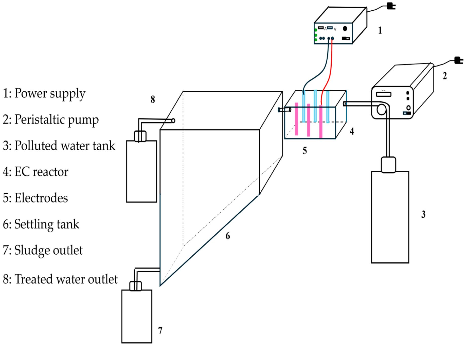
2.1. Experimental Set-Up
2.2. Experimental Procedures
3. Results and Discussions
3.1. Effect of Electrode Configuration
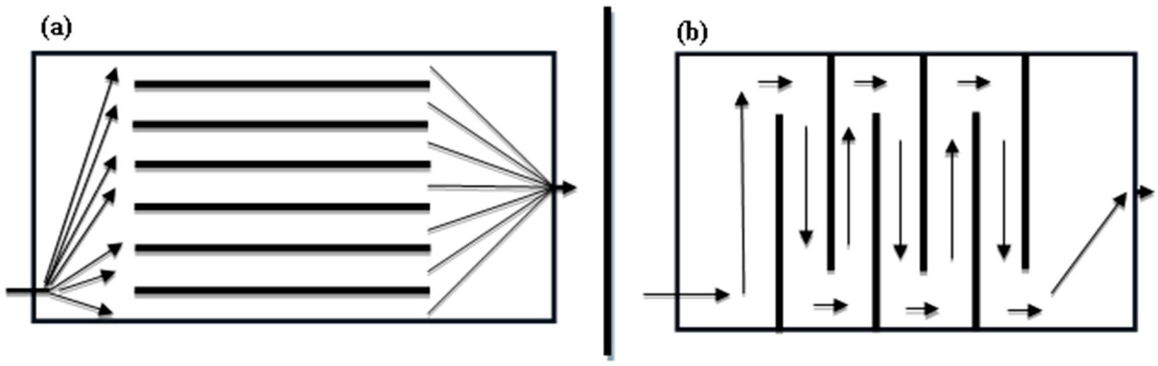
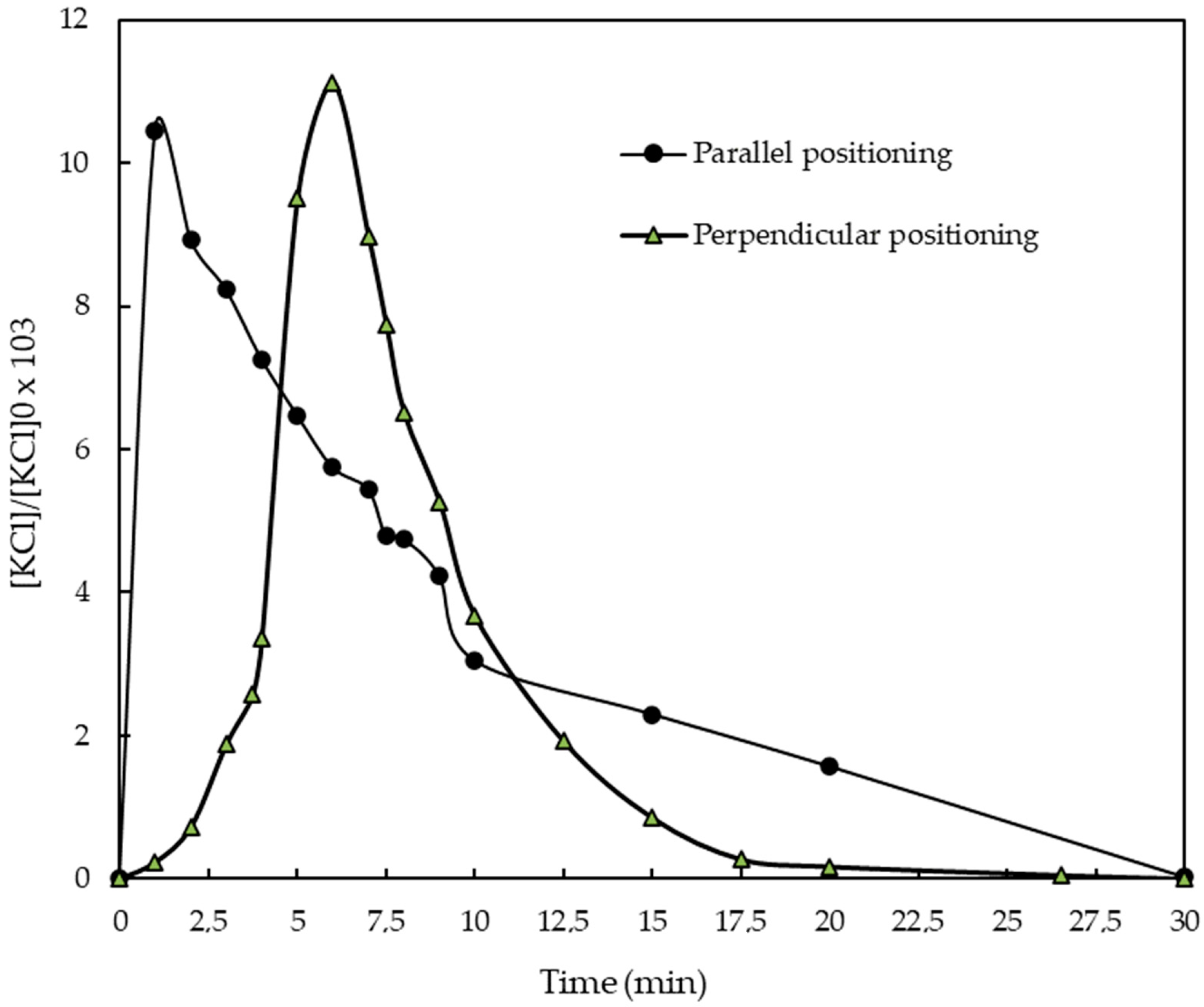
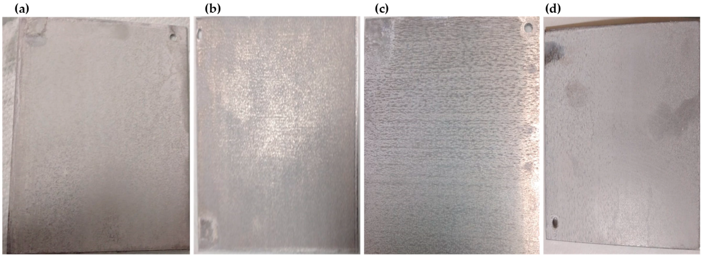
3.1.1. Effect of Electrode Positioning on Aluminum Dissolution
- Pitting corrosion of the electrodes by chloride ions in the solution ([Cl−] = 490 mg·L−1).
- Aluminum corrosion by pitting at the anode (Reaction (5)).
- The attack of hydroxide ions (generated by water reduction) on aluminum cathodic electrode ((Reaction (6))
3.1.2. Effect of Electrode Positioning on Fluoride Removal Efficiency and Electrical Energy Consumption
3.2. Effect of Electrical Connection Mode
3.2.1. Effect of Electrode Connection Mode on Total Dissolved Aluminum
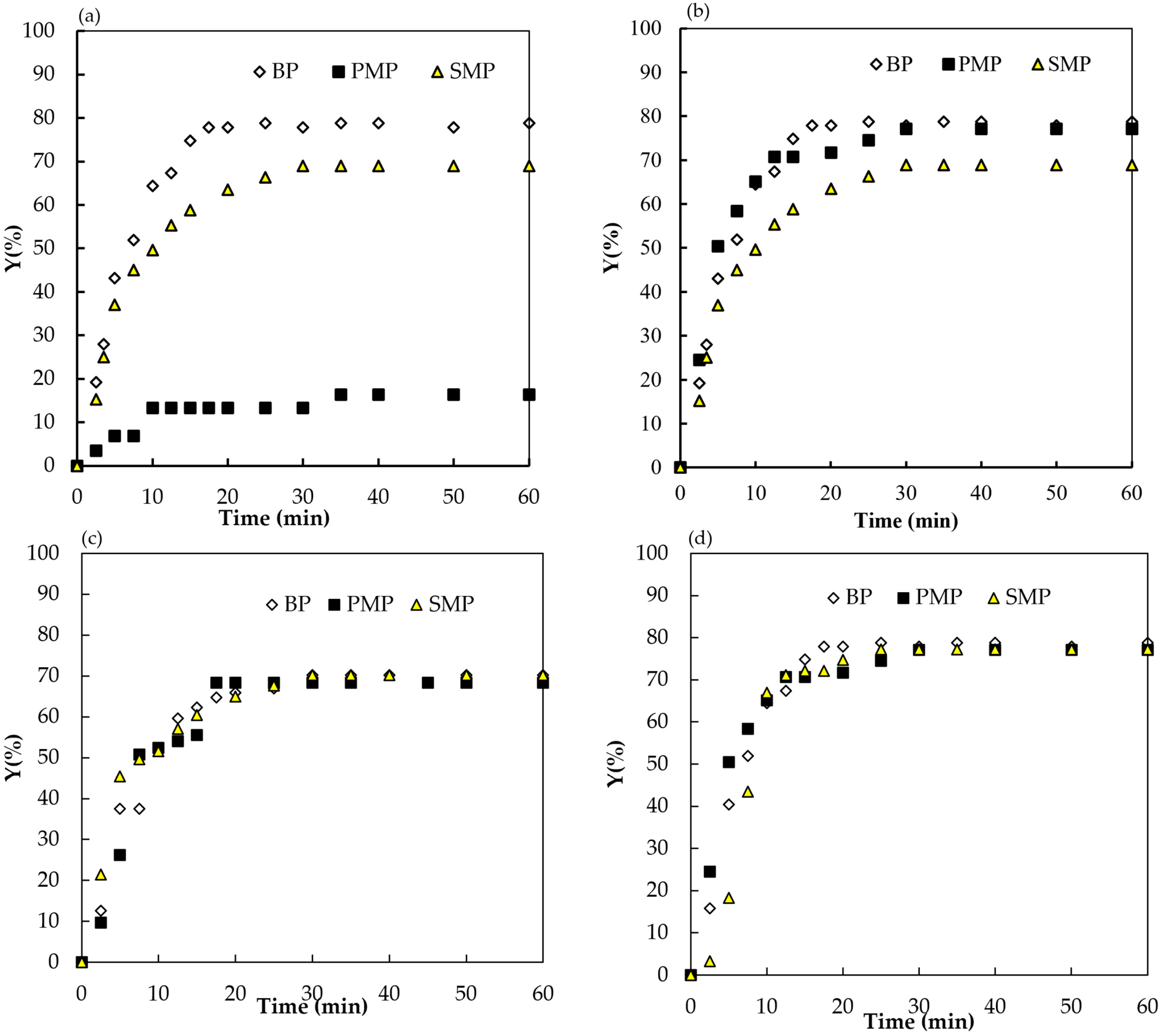
3.2.2. Effect of Electrode Connection Mode on Fluoride Removal Yield
3.2.3. Effect of Electrode Connection Mode on Energetic Consumption
3.3. Efficiency of Polarity Reversal in Deposit Removal
4. Conclusions
Author Contributions
Funding
Institutional Review Board Statement
Informed Consent Statement
Data Availability Statement
Conflicts of Interest
References
- Chakraborti, D.; Rahman, M.M.; Chatterjee, A.; Das, D.; Das, B.; Nayak, B.; Pal, A.; Chowdhury, U.K.; Ahmed, S.; Biswas, B.K.; et al. Fate of over 480 Million Inhabitants Living in Arsenic and Fluoride Endemic Indian Districts: Magnitude, Health, Socio-Economic Effects and Mitigation Approaches. J. Trace Elem. Med. Biol. 2016, 38, 33–45. [Google Scholar] [CrossRef]
- Dissanayake, C.B. The Fluoride Problem in the Ground Water of Sri Lanka—Environmental Management and Health. Int. J. Environ. Stud. 1991, 38, 137–155. [Google Scholar] [CrossRef]
- Shaji, E.; Sarath, K.V.; Santosh, M.; Krishnaprasad, P.K.; Arya, B.K.; Babu, M.S. Fluoride Contamination in Groundwater: A Global Review of the Status, Processes, Challenges, and Remedial Measures. Geosci. Front. 2024, 15, 101734. [Google Scholar] [CrossRef]
- WHO. Guidelines for Drinking Water Quality; WHO: Geneva, Switzerland, 2011; Volume 4. [Google Scholar]
- Ben Nasr, A.; Charcosset, C.; Amar, R.B.; Walha, K. Fluoride Removal from Aqueous Solution by Purolite A520E Resin: Kinetic and Thermodynamics Study. Desalination Water Treat. 2014, 54, 1604–1611. [Google Scholar] [CrossRef]
- De, A.; Das, A.; Joardar, M.; Mridha, D.; Majumdar, A.; Das, J.; Roychowdhury, T. Investigating Spatial Distribution of Fluoride in Groundwater with Respect to Hydro-Geochemical Characteristics and Associated Probabilistic Health Risk in Baruipur Block of West Bengal, India. Sci. Total Environ. 2023, 886, 163877. [Google Scholar] [CrossRef]
- Dhifallah, S.; Attour, A.; Vial, C.; Zagrouba, F.; Audonnet, F. Defluoridation of Tap Water by Electrocoagulation and Fluoride Adsorption on Aluminum Hydroxide Flocs. Water Supply 2024, 24, 1409–1424. [Google Scholar] [CrossRef]
- Shen, F.; Chen, X.; Gao, P.; Chen, G. Electrochemical Removal of Fluoride Ions from Industrial Wastewater. Chem. Eng. Sci. 2003, 58, 987–993. [Google Scholar] [CrossRef]
- Vishwakarma, V.; Srivastava, J.K. Removal of Fluoride from Ground Water by Electrocoagulation Method: Investigation of Process Parameters, Kinetic Analysis, and Operating Cost. J. Dispers. Sci. Technol. 2023, 1–11. [Google Scholar] [CrossRef]
- Kimambo, V.; Bhattacharya, P.; Mtalo, F.; Mtamba, J.; Ahmad, A. Fluoride Occurrence in Groundwater Systems at Global Scale and Status of Defluoridation—State of the Art. Groundw. Sustain. Dev. 2019, 9, 100223. [Google Scholar] [CrossRef]
- Podgorski, J.; Berg, M. Global Analysis and Prediction of Fluoride in Groundwater. Nat. Commun. 2022, 13, 4232. [Google Scholar] [CrossRef]
- Ben Grich, N.; Attour, A.; Le Page Mostefa, M.; Tlili, M.; Lapicque, F. Fluoride Removal from Water by Electrocoagulation with Aluminium Electrodes: Effect of the Water Quality. Desalination Water Treat. 2019, 144, 145–155. [Google Scholar] [CrossRef]
- Sugita, H.; Morimoto, K.; Saito, T.; Hara, J. Simultaneous Removal of Arsenate and Fluoride Using Magnesium-Based Adsorbents. Sustainability 2024, 16, 1774. [Google Scholar] [CrossRef]
- Vences-Alvarez, E.; Flores-Arciniega, J.L.; Flores-Zuñiga, H.; Rangel-Mendez, J.R. Fluoride Removal from Water by Ceramic Oxides from Cerium and Manganese Solutions. J. Mol. Liq. 2019, 286, 110880. [Google Scholar] [CrossRef]
- You, S.; Cao, S.; Mo, C.; Zhang, Y.; Lu, J. Synthesis of High Purity Calcium Fluoride from Fluoride-Containing Wastewater. Chem. Eng. J. 2023, 453, 139733. [Google Scholar] [CrossRef]
- Paul, M.; Jons, S.D. Chemistry and Fabrication of Polymeric Nanofiltration Membranes: A Review. Polymer 2016, 103, 417–456. [Google Scholar] [CrossRef]
- Damtie, M.M.; Woo, Y.C.; Kim, B.; Hailemariam, R.H.; Park, K.-D.; Shon, H.K.; Park, C.; Choi, J.-S. Removal of Fluoride in Membrane-Based Water and Wastewater Treatment Technologies: Performance Review. J. Environ. Manag. 2019, 251, 109524. [Google Scholar] [CrossRef]
- Ben Grich, N.; Attour, A.; Le Page Mostefa, M.; Guesmi, S.; Tlili, M.; Lapicque, F. Fluoride Removal from Water by Electrocoagulation: Effect of the Type of Water and the Experimental Parameters. Electrochim. Acta 2019, 316, 257–265. [Google Scholar] [CrossRef]
- Gmar, S.; Ben Salah Sayadi, I.; Helali, N.; Tlili, M.; Ben Amor, M. Desalination and Defluoridation of Tap Water by Electrodialysis. Environ. Process. 2015, 2, 209–222. [Google Scholar] [CrossRef]
- Martínez-Villafañe, J.F.; Ortiz-Cuellar, J.C.; Galindo-Valdés, J.S.; Cepeda-Rodríguez, F.; Gómez-Casas, J.; Rodríguez-Rosales, N.A.; Gómez-Casas, O.; Muñiz-Valdez, C.R. Interelectrode Distance Analysis in the Water Defluoridation by Electrocoagulation Reactor. Sustainability 2022, 14, 12096. [Google Scholar] [CrossRef]
- Braik, S.; Amor, T.B.; Michelin, L.; Rigolet, S.; Bonne, M.; Lebeau, B.; Hafiane, A. Natural Water Defluoridation by Adsorption on Laponite Clay. Water Sci. Technol. 2022, 85, 1701–1719. [Google Scholar] [CrossRef]
- Mohapatra, M.; Anand, S.; Mishra, B.K.; Giles, D.E.; Singh, P. Review of Fluoride Removal from Drinking Water. J. Environ. Manag. 2009, 91, 67–77. [Google Scholar] [CrossRef] [PubMed]
- Lacson, C.F.Z.; Lu, M.-C.; Huang, Y.-H. Calcium-Based Seeded Precipitation for Simultaneous Removal of Fluoride and Phosphate: Its Optimization Using BBD-RSM and Defluoridation Mechanism. J. Water Process Eng. 2022, 47, 102658. [Google Scholar] [CrossRef]
- Shao, S.; Ma, B.; Chen, Y.; Zhang, W.; Wang, C. Behavior and Mechanism of Fluoride Removal from Aqueous Solutions by Using Synthesized CaSO4·2H2O Nanorods. Chem. Eng. J. 2021, 426, 131364. [Google Scholar] [CrossRef]
- Bejaoui, I.; Mnif, A.; Hamrouni, B. Performance of Reverse Osmosis and Nanofiltration in the Removal of Fluoride from Model Water and Metal Packaging Industrial Effluent. Sep. Sci. Technol. 2014, 49, 1135–1145. [Google Scholar] [CrossRef]
- Yadav, K.K.; Kumar, S.; Pham, Q.B.; Gupta, N.; Rezania, S.; Kamyab, H.; Yadav, S.; Vymazal, J.; Kumar, V.; Tri, D.Q.; et al. Fluoride Contamination, Health Problems and Remediation Methods in Asian Groundwater: A Comprehensive Review. Ecotoxicol. Environ. Saf. 2019, 182, 109362. [Google Scholar] [CrossRef] [PubMed]
- Al-Qodah, Z.; Tawalbeh, M.; Al-Shannag, M.; Al-Anber, Z.; Bani-Melhem, K. Combined Electrocoagulation Processes as a Novel Approach for Enhanced Pollutants Removal: A State-of-the-Art Review. Sci. Total Environ. 2020, 744, 140806. [Google Scholar] [CrossRef] [PubMed]
- Zhang, M.; Tan, X.; Ding, W.; Jiang, Z.; He, K.; Zhao, B.; Takeuchi, H.; Huang, Y. Aluminum-Based Electrocoagulation for Residual Fluoride Removal during per- and Polyfluoroalkyl Substances (PFASs) Wastewater Treatment. Sep. Purif. Technol. 2023, 308, 122989. [Google Scholar] [CrossRef]
- Lu, J.; Zhang, P.; Li, J. Electrocoagulation Technology for Water Purification: An Update Review on Reactor Design and Some Newly Concerned Pollutants Removal. J. Environ. Manag. 2021, 296, 113259. [Google Scholar] [CrossRef] [PubMed]
- Nidheesh, P.V.; Oladipo, A.A.; Yasri, N.G.; Laiju, A.R.; Cheela, V.R.S.; Thiam, A.; Asfaha, Y.G.; Kanmani, S.; Roberts, E.P.L. Emerging Applications, Reactor Design and Recent Advances of Electrocoagulation Process. Process Saf. Environ. Prot. 2022, 166, 600–616. [Google Scholar] [CrossRef]
- Picard, T.; Cathalifaud-Feuillade, G.; Mazet, M.; Vandensteendam, C. Cathodic Dissolution in the Electrocoagulation Process Using Aluminium Electrodes. J. Environ. Monit. 2000, 2, 77–80. [Google Scholar] [CrossRef]
- Société Tunisienne de L’électricité et du Gaz Les Tarifs de L’électricité En Moyenne et Haute Tension à Compter Du 1er Mai 2024. Available online: https://www.webdo.tn/fr/actualite/national/tunisie-la-steg-dement-toute-augmentation-des-tarifs-de-l-electricite-et-du-gaz/213969 (accessed on 20 May 2024).
- L’ABS du Decolletage. Available online: https://www.le-decolletage.fr/prix-et-cours-de-l-aluminium.html?fbclid=IwZXh0bgNhZW0CMTAAAR3HSektW7t1DKrU49V1-K_LuhBa1WhzPIqUC4_v_2x1r9V-KLU94rjvnPI_aem_ZmFrZWR1bW15MTZieXRlcw (accessed on 20 May 2024).
- Apshankar, K.R.; Goel, S. Review and Analysis of Defluoridation of Drinking Water by Electrocoagulation. J. Water Supply Res. Technol.—Aqua 2018, 67, 297–316. [Google Scholar] [CrossRef]
- Khaled, B.; Wided, B.; Béchir, H.; Elimame, E.; Mouna, L.; Zied, T. Investigation of Electrocoagulation Reactor Design Parameters Effect on the Removal of Cadmium from Synthetic and Phosphate Industrial Wastewater. Arab. J. Chem. 2019, 12, 1848–1859. [Google Scholar] [CrossRef]
- Mameri, N.; Yeddou, A.R.; Lounici, H.; Belhocine, D.; Grib, H.; Bariou, B. Defluoridation of Septentrional Sahara Water of North Africa by Electrocoagulation Process Using Bipolar Aluminium Electrodes. Water Res. 1998, 32, 1604–1612. [Google Scholar] [CrossRef]
- Landolt, D. Corrosion and Surface Chemistry of Metals, 1st ed.; EPFL Press English Imprint: Lausanne, Switzerland, 2007. [Google Scholar]
- Abbas, M.; Magaud, P.; Gao, Y.; Geoffroy, S. Migration of Finite Sized Particles in a Laminar Square Channel Flow from Low to High Reynolds Numbers. Phys. Fluids 2014, 26, 123301. [Google Scholar] [CrossRef]
- Martel, J.M.; Toner, M. Inertial Focusing in Microfluidics. Annu. Rev. Biomed. Eng. 2014, 16, 371–396. [Google Scholar] [CrossRef] [PubMed]
- Bayar, S.; Yıldız, Y.Ş.; Yılmaz, A.E.; İrdemez, Ş. The Effect of Stirring Speed and Current Density on Removal Efficiency of Poultry Slaughterhouse Wastewater by Electrocoagulation Method. Desalination 2011, 280, 103–107. [Google Scholar] [CrossRef]
- Can, B.Z.; Boncukcuoglu, R.; Yilmaz, A.E.; Fil, B.A. Effect of Some Operational Parameters on the Arsenic Removal by Electrocoagulation Using Iron Electrodes. J. Environ. Health Sci. Eng. 2014, 12, 95. [Google Scholar] [CrossRef] [PubMed]
- Tahreen, A.; Jami, M.S.; Ali, F. Role of Electrocoagulation in Wastewater Treatment: A Developmental Review. J. Water Process Eng. 2020, 37, 101440. [Google Scholar] [CrossRef]
- Ingelsson, M.; Yasri, N.; Roberts, E.P.L. Electrode Passivation, Faradaic Efficiency, and Performance Enhancement Strategies in Electrocoagulation—A Review. Water Res. 2020, 187, 116433. [Google Scholar] [CrossRef]
- Dubrawski, K.L.; Van Genuchten, C.M.; Delaire, C.; Amrose, S.E.; Gadgil, A.J.; Mohseni, M. Production and Transformation of Mixed-Valent Nanoparticles Generated by Fe(0) Electrocoagulation. Environ. Sci. Technol. 2015, 49, 2171–2179. [Google Scholar] [CrossRef]
- Amri, I.; Meldha, Z.; Herman, S.; Karmila, D.; Ramadani, F.; Nirwana. Effects of Electric Voltage and Number of Aluminum Electrodes on Continuous Electrocoagulation of Liquid Waste from the Palm Oil Industry. Mater. Today Proc. 2023, 87, 345–349. [Google Scholar] [CrossRef]
- Chen, M.; Zhou, L. Fluoride Removal from Drinking Water with Electrocoagulation: Comparison of Different Electrode Connection Modes. Sci. Talks 2023, 6, 100209. [Google Scholar] [CrossRef]
- Irki, S. Decolorization of Methyl Orange (MO) by Electrocoagulation (EC) Using Iron Electrodes under a Magnetic Field (MF). II. Effect of Connection Mode. World J. Appl. Chem. 2018, 3, 56. [Google Scholar] [CrossRef]
- Kobya, M.; Ulu, F.; Gebologlu, U.; Demirbas, E.; Oncel, M.S. Treatment of Potable Water Containing Low Concentration of Arsenic with Electrocoagulation: Different Connection Modes and Fe–Al Electrodes. Sep. Purif. Technol. 2011, 77, 283–293. [Google Scholar] [CrossRef]
- Mahmood, M.; Yasri, N.; Fuladpanjeh-Hojaghan, B.; Roberts, E.P.L. Influence of Operating Conditions on the Removal of Silica and Hardness by Continuous Electrocoagulation. J. Environ. Chem. Eng. 2022, 10, 108899. [Google Scholar] [CrossRef]
- Chow, H.; Ingelsson, M.; Roberts, E.P.L.; Pham, A.L.-T. How Does Periodic Polarity Reversal Affect the Faradaic Efficiency and Electrode Fouling during Iron Electrocoagulation? Water Res. 2021, 203, 117497. [Google Scholar] [CrossRef]
- Castro Carias, M. Evaluation of Aluminum Dissolution, Current Density, and Pitting Patterns During Electrocoagulation. Master’s Thesis, University of South Florida, Tampa, FL, USA, 2022. [Google Scholar]


| Real Water Composition | Synthetic Water Composition | |
|---|---|---|
| F− (mg·L−1) | 3.50 ± 0.02 | 3.50 ± 0.02 |
| Ca2+ (mg·L−1) | 320 ± 1 | 320 ± 1 |
| Cl− (mg·L−1) | 490 ± 1 | 490 ± 1 |
| K+ (mg·L−1) | 10.2 ± 0.2 | 1.4 ± 0.2 |
| Na+ (mg·L−1) | 308.9 ± 0.2 | 220.0 ± 0.2 |
| SO42− (mg·L−1) | 1169 ± 1 | 1169 ± 1 |
| Mg2+ (mg·L−1) | 192 ± 1 | 192 ± 1 |
| HCO3− (mg·L−1) | 183 ± 1 | 183 ± 1 |
| PO43− (mg·L−1) | 3.4 ± 0.1 | 3.4 ± 0.1 |
| Scenario 1: Same current and number of electrodes. Nel = 6 electrodes, I = 0.5 A, Q = 20 L·h−1 | ||||
| Connection mode | P-MP | BP | S-MP | |
| i (mA·cm−2) | 0.95 | 4.7 | 4.7 | |
| Ncell | 5 | 5 | 3 | |
| Electrical assembly |  |  |  | |
| Scenario 2: Same current density and number of electrodes. Nel = 6 electrodes, i = 4.7 mA·cm−2, Q = 20 L·h−1 | ||||
| I (A) | 2.5 | 0.5 | 0.5 | |
| Ncell | 5 | 5 | 3 | |
| Electrical assembly |  | 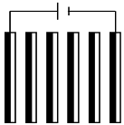 |  | |
| Scenario 3: Same current density and same number of electrochemical cells. i = 4.7 mA·cm−2, Q = 20 L·h−1 | ||||
| Ncell = 3 | Nel | 4 | 4 | 6 |
| I (A) | 1.5 | 0.5 | 0.5 | |
| Electrical assembly |  | 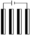 |  | |
| Nel | 6 | 6 | 10 | |
| I (A) | 2.5 | 0.5 | 0.5 | |
| Ncell = 5 | Electrical assembly | 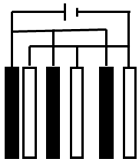 |  |  |
| i (mA·cm−2) | 4.7 | 6.6 | 9.5 | |
| Parallel positioning | 0.595 | 0.758 | 1.060 | |
| (g·h−1) | Perpendicular positioning | 1.026 | 1.338 | 1.790 |
| (g·h−1) | Independent of positioning | 0.839 | 1.175 | 1.679 |
| η | Parallel positioning | 0.71 | 0.64 | 0.63 |
| Perpendicular positioning | 1.22 | 1.13 | 1.06 |
| i (mA·cm−2) | 4.7 | 6.6 | 9.5 | |
| Parallel positioning | Upar (V) | 12 | 15.2 | 19.4 |
| Ppar (kWh·m−3) | 0.299 | 0.532 | 0.970 | |
| Perpendicular positioning | Uper (V) | 16.2 | 21.1 | 27.1 |
| Pper (kWh·m−3) | 0.405 | 0.739 | 1.354 |
| Connection Mode | P-MP | BP | S-MP | ||
|---|---|---|---|---|---|
| Scenario 1: Nel = 6, I = 0.5 A | (g·h−1) | 0.252 | 1.026 | 0.714 | |
| (g·h−1) | 0.168 | 0.839 | 0.504 | ||
| η | 1.50 | 1.22 | 1.42 | ||
| Scenario 2: Nel = 6, i = 4.7 mA·cm−2 | (g·h−1) | 1.045 | 1.026 | 0.714 | |
| (g·h−1) | 0.8392 | 0.839 | 0.504 | ||
| η | 1.24 | 1.22 | 1.42 | ||
| Scenario 3: i= 4.7 mA·cm−2, Ncell = 3 or 5 cells | Ncell = 3: | (g·h−1) | 0.723 | 0.713 | 0.714 |
| (g·h−1) | 0.504 | 0.504 | 0.504 | ||
| η | 1.44 | 1.42 | 1.42 | ||
| Ncell = 5: | (g·h−1) | 1.045 | 1.026 | 1.095 | |
| (g·h−1) | 0.839 | 0.839 | 0.839 | ||
| η | 1.24 | 1.22 | 1.30 | ||
| Half-cycle duration (HCD) (min) | ∞ | 0.5 | 1 | 2 | 5 |
| Number of inversions in one hour (NI) | 0 | 119 | 59 | 29 | 11 |
| (g·h−1) | 1.026 | 0.751 | 0.844 | 0.958 | 0.964 |
Disclaimer/Publisher’s Note: The statements, opinions and data contained in all publications are solely those of the individual author(s) and contributor(s) and not of MDPI and/or the editor(s). MDPI and/or the editor(s) disclaim responsibility for any injury to people or property resulting from any ideas, methods, instructions or products referred to in the content. |
© 2024 by the authors. Licensee MDPI, Basel, Switzerland. This article is an open access article distributed under the terms and conditions of the Creative Commons Attribution (CC BY) license (https://creativecommons.org/licenses/by/4.0/).
Share and Cite
Dhifallah, S.; Attour, A.; Vial, C.; Zagrouba, F.; Audonnet, F. Continuous Electrocoagulation for a Sustainable Water Treatment: Effects of Electrode Configuration, Electrical Connection Mode, and Polarity Reversal on Fluoride Removal. Sustainability 2024, 16, 5765. https://doi.org/10.3390/su16135765
Dhifallah S, Attour A, Vial C, Zagrouba F, Audonnet F. Continuous Electrocoagulation for a Sustainable Water Treatment: Effects of Electrode Configuration, Electrical Connection Mode, and Polarity Reversal on Fluoride Removal. Sustainability. 2024; 16(13):5765. https://doi.org/10.3390/su16135765
Chicago/Turabian StyleDhifallah, Sirin, Anis Attour, Christophe Vial, Fethi Zagrouba, and Fabrice Audonnet. 2024. "Continuous Electrocoagulation for a Sustainable Water Treatment: Effects of Electrode Configuration, Electrical Connection Mode, and Polarity Reversal on Fluoride Removal" Sustainability 16, no. 13: 5765. https://doi.org/10.3390/su16135765
APA StyleDhifallah, S., Attour, A., Vial, C., Zagrouba, F., & Audonnet, F. (2024). Continuous Electrocoagulation for a Sustainable Water Treatment: Effects of Electrode Configuration, Electrical Connection Mode, and Polarity Reversal on Fluoride Removal. Sustainability, 16(13), 5765. https://doi.org/10.3390/su16135765