Reduction of Methane Emissions from Natural Gas Integral Compressor Engines through Fuel Injection Control
Abstract
:1. Introduction
2. Materials and Methods
2.1. Experimental Study
2.2. Computational Study
2.2.1. Baseline Case
2.2.2. Late Cycle High-Pressure Fuel Injection Cases
3. Results and Discussion
3.1. Experimental Study
3.2. Computational Study
3.3. Comparison between Experimental and Computational Data
4. Conclusions
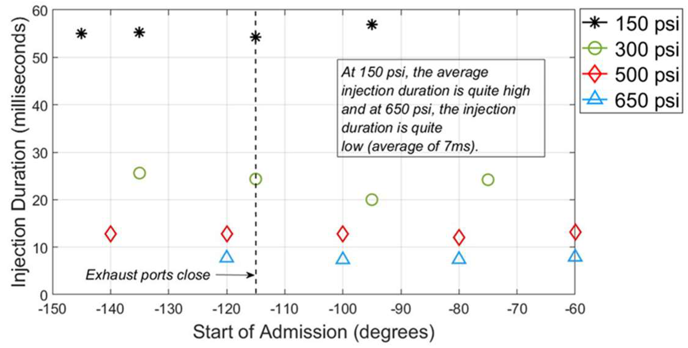
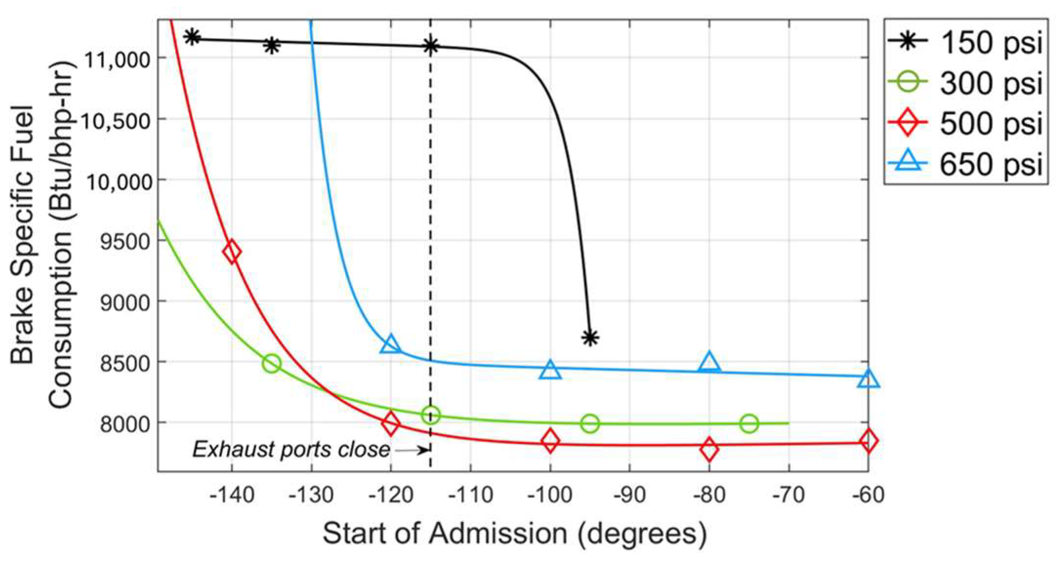
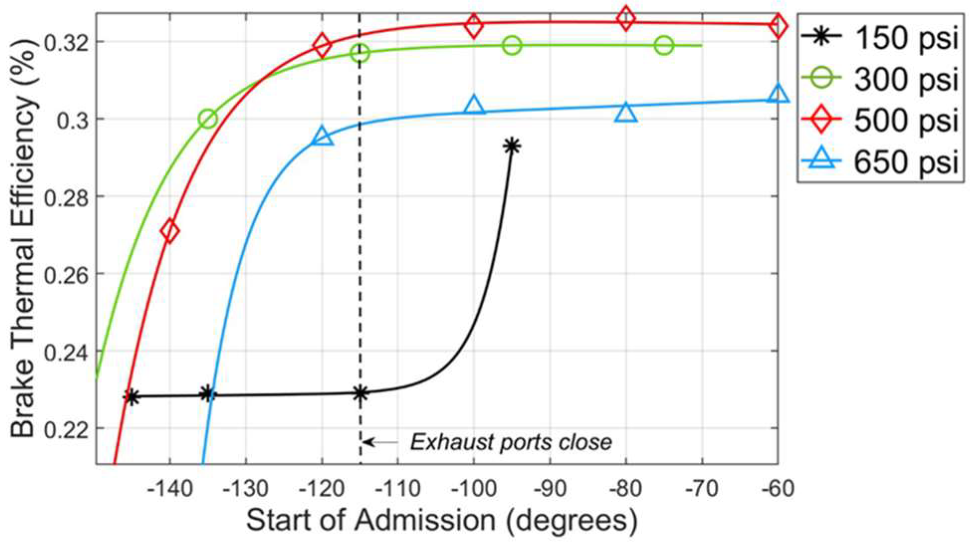
- There is an optimal point for exhaust methane emissions based on injection timing for every injection pressure, and it occurs late in the cycle. The lowest methane emissions are encountered with fuel injection at a pressure of 500 psi and an SOA value of −100 degrees, which constitutes a 22.4% decrease from the nominal point (500 psi, −120 degrees SOA) methane emissions. There are no performance penalties or emission penalties for this methane emission reduction at the optimal point, as the COVs are minimized and fuel consumption is reduced. There are also no emissions penalties due to the NOx control loop employed, which keeps NOx constant. There are also reduced CO, THC, VOCs, and formaldehyde emissions at the optimal points for 500 and 650 psi, but it is not necessarily so for the cases at 150 and 300 psi, where these emissions tend to increase with late-cycle fuel injection.
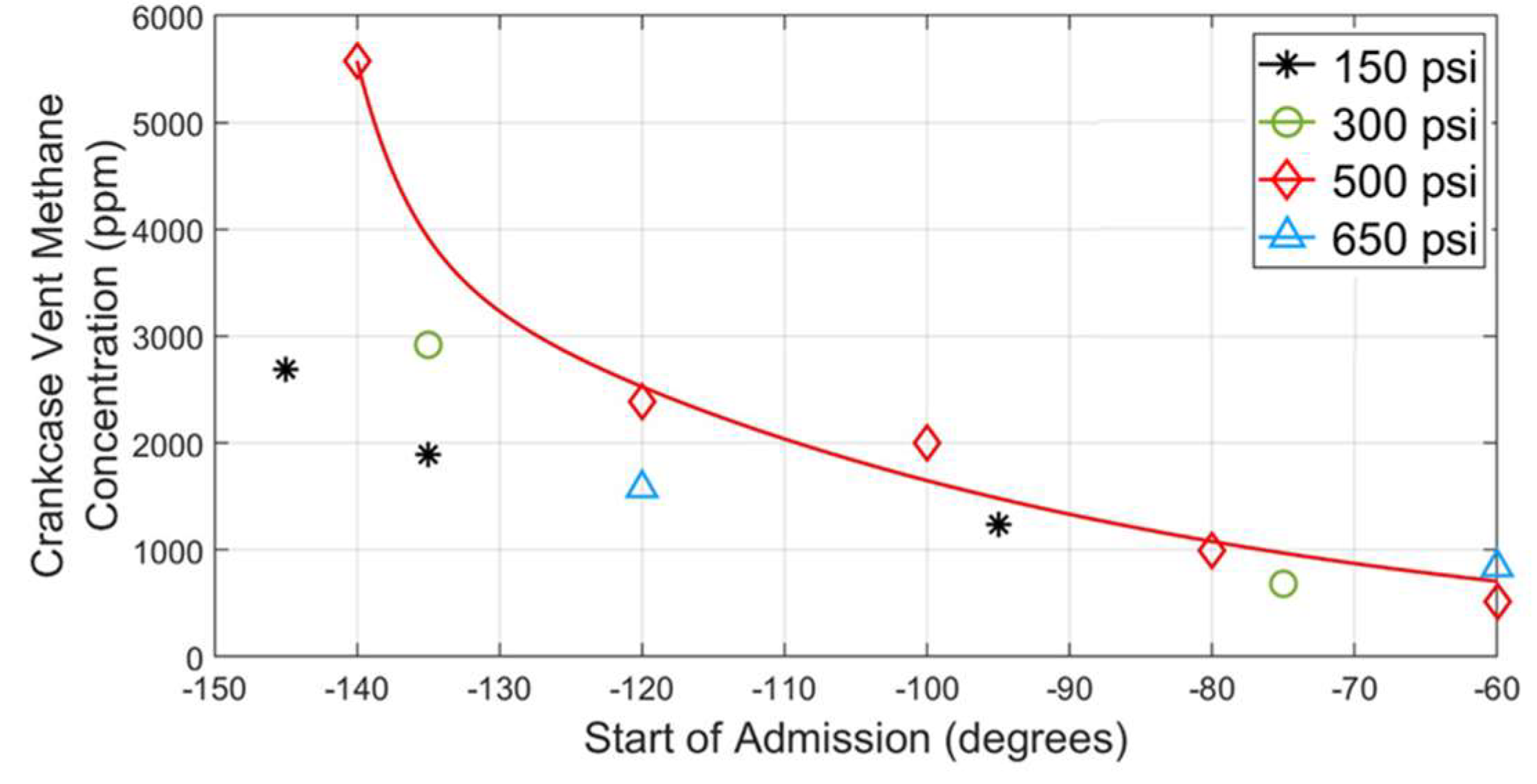
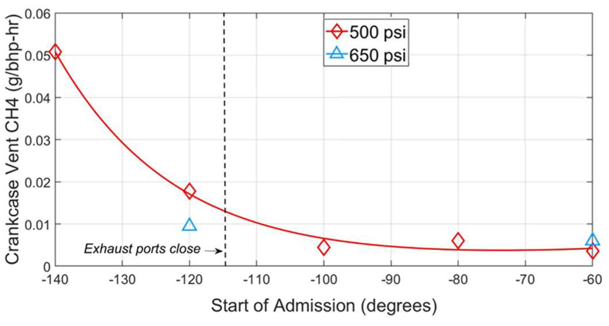
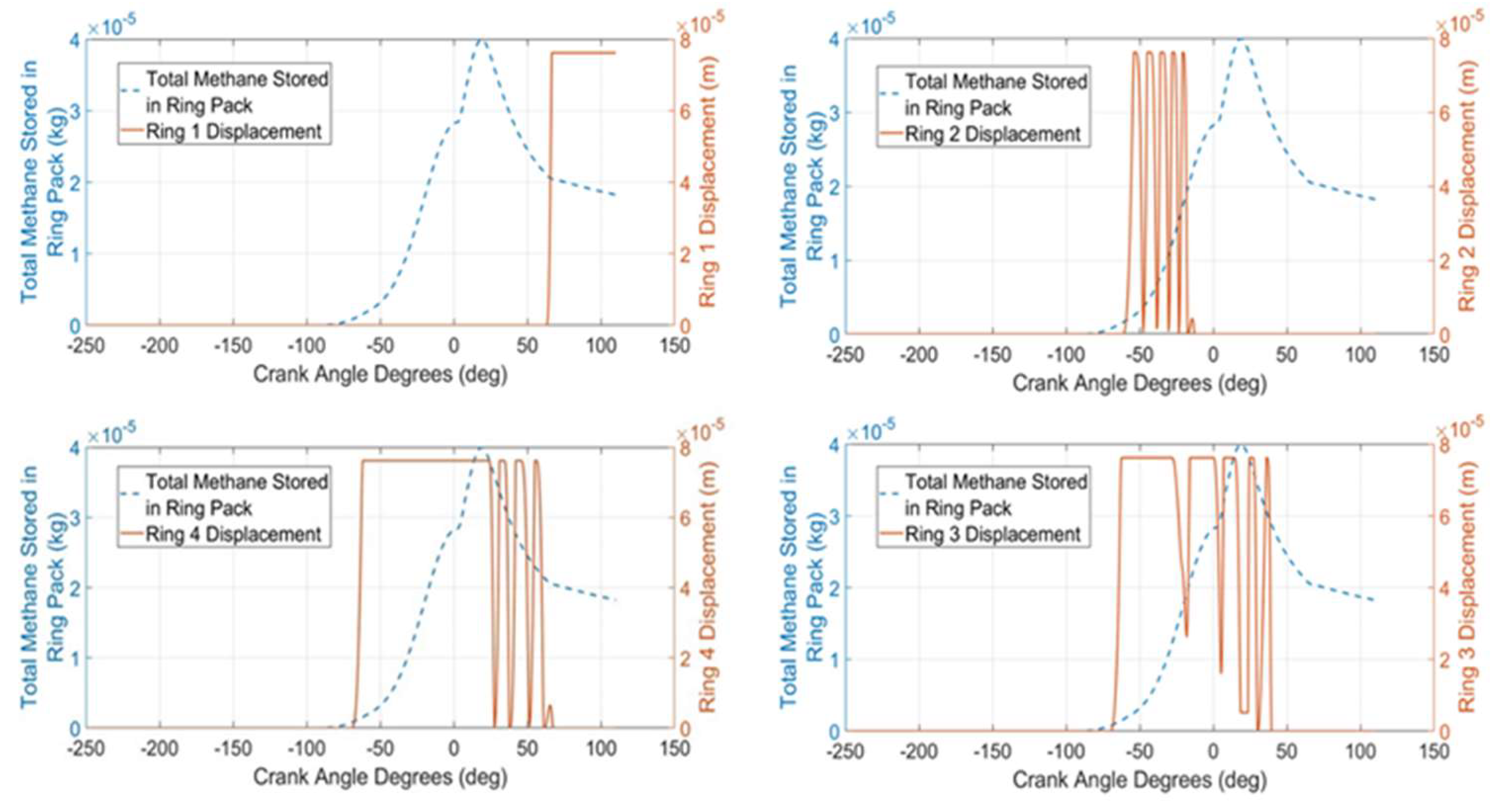
- Late-cycle fuel injection reduces crankcase methane emissions as less unburned fuel can flow to the crankcase when fuel is injected after exhaust ports close. Crankcase methane emissions are influenced by fuel injection timing, as shown both by experimental data and results from computational simulations. The measured crankcase vent methane in the experimental study has a constant decline at 500 psi as the SOA values move later in the cycle. The amount of methane blowby through the ring pack also declines with late-cycle fuel injection, as shown through the simulation results.
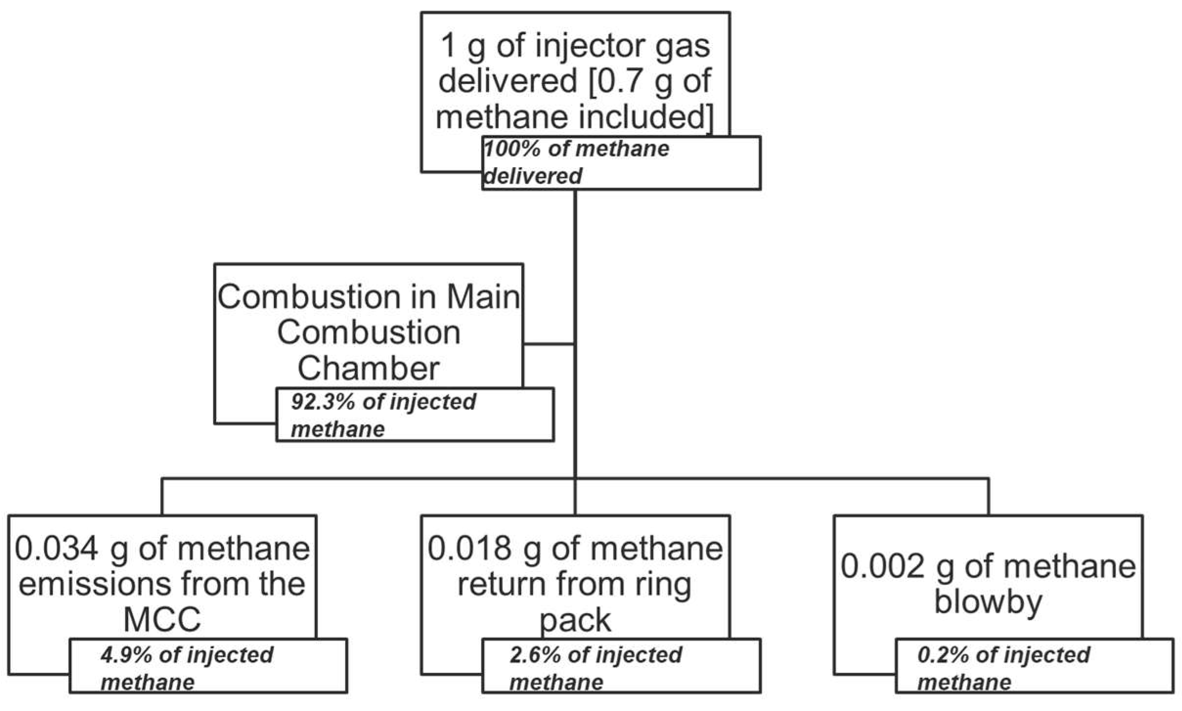
- The ring pack contributes a significant portion to methane emissions in large-bore, natural-gas-fueled two-stroke engines. Approximately one-third of the methane emissions from large bore engines come from methane residuals in the crevice volumes in the compression ring pack of the engine.
Author Contributions
Funding
Institutional Review Board Statement
Data Availability Statement
Acknowledgments
Conflicts of Interest
References
- European Commission. Energy, Climate Change, Environment—Methane Emissions. Available online: https://energy.ec.europa.eu/topics/carbon-management-and-fossil-fuels/methane-emissions_en (accessed on 16 May 2024).
- Energy Information Agency. Natural Gas Compressor Stations on the Interstate Pipeline Network: Developments Since 1996. 2007. Available online: https://www.eia.gov/naturalgas/articles/compressor96index.php / (accessed on 16 May 2024).
- Li, M.; Wu, H.; Zhang, T.; Shen, B.; Zhang, Q.; Li, Z. A comprehensive review of pilot ignited high pressure direct injection natural gas engines: Factors affecting combustion, emissions and performance. Renew. Sustain. Energy Rev. 2020, 119, 109653. [Google Scholar] [CrossRef]
- Kim, D.; Shin, J.; Son, Y.; Park, S. Characteristics of in-cylinder flow and mixture formation in a high-pressure spray-guided gasoline direct-injection optically accessible engine using PIV measurements and CFD. Energy Convers. Manag. 2021, 248, 114819. [Google Scholar] [CrossRef]
- Hoffmann, G.; Befrui, B.; Berndorfer, A.; Piock, W.F. Fuel System Pressure Increase for Enhanced Performance of GDi Multi-Hole Injection Systems. SAE Int. J. Engines 2014, 7, 519–527. [Google Scholar] [CrossRef]
- Alkidas, A.C. Combustion-chamber crevices: The major source of engine-out hydrocarbon emissions under fully warmed conditions. Prog. Energy Combust. Sci. 1999, 25, 253–273. [Google Scholar] [CrossRef]
- Kim, C.; Bae, C.; Choi, S. Gas Flows Through the Inter-Ring Crevice and Their Influence on UHC Emissions. J. Fuels Lubr. 1999, 108, 1181–1191. [Google Scholar]
- Thompson, N.D.; Wallace, J.S. Effect of Engine Operating Variables and Piston and Ring Parameters on Crevice Hydrocarbon Emissions. J. Engines 1994, 103, 718–736. [Google Scholar]
- Salazar, V.M.; Ghandhi, J.B. Initial Estimation of the Piston Ring Pack Contribution to Hydrocarbon Emissions from a Small Engine. J. Engines 2007, 116, 1280–1291. [Google Scholar]
- Baratta, M.; Misul, D.; Viglione, L.; Xu, J. Combustion chamber design for a high-performance natural gas engine: CFD modeling and experimental investigation. Energy Convers. Manag. 2019, 192, 221–231. [Google Scholar] [CrossRef]
- Duan, X.; Li, Y.; Liu, Y.; Liu, J.; Wang, S.; Guo, G. Quantitative investigation the influences of the injection timing under single and double injection strategies on performance, combustion and emissions characteristics of a GDI SI engine fueled with gasoline/ethanol blend. Fuel 2020, 260, 116363. [Google Scholar] [CrossRef]
- Venugopal, T.; Ramesh, A. Experimental studies on the effect of injection timing in a SI engine using dual injection of n-butanol and gasoline in the intake port. Fuel 2014, 115, 295–305. [Google Scholar] [CrossRef]
- Willson, B.; Hutcherson, G.; Hawley, S.; Willett, K. Relative Performance of High-Pressure Fuel Gas Delivery. In Proceedings of the GMRC Gas Machinery Conference, Austin, TX, USA, 6–8 October 1997. [Google Scholar]
- Ladd, J.; Neuner, B.; Olsen, D.B. Variable Fuel Composition Air Fuel Ratio Control of Lean Burn Engines. 2016. Available online: https://www.prci.org/Research/CompressorPumpStation/CPSProjects/CPS-14J/3427/37611.aspx?source=generalSearch (accessed on 28 May 2024).
- Richards, K.J.; Senecal, P.K.; Pomraning, E. CONVERGE Studio; Convergent Science: Madison, WI, USA, 2024. [Google Scholar]
- Richards, K.J.; Senecal, P.K.; Pomraning, E. CONVERGE 3.1 Manual; Convergent Science: Madison, WI, USA, 2023. [Google Scholar]
- Namazian, M. Studies of Combustion and Crevice Gas Motion in a Flow-Visualization Spark-Ignition Engine. Ph.D. Thesis, Massachussets Institute of Technology, Cambridge, MA, USA, 1981. [Google Scholar]
- Rakopoulos, C.D.; Kosmadakis, G.M.; Dimaratos, A.M.; Pariotis, E.G. Investigating the effect of crevice flow on internal combustion engines using a new simple crevice model implemented in a CFD code. Appl. Energy 2011, 88, 111–126. [Google Scholar] [CrossRef]
- Kurbet, S.N.; Kumar, R.K. Finite element modelling of piston-ring dynamics and blow-by estimation in a four-cylinder diesel engine. Proc. Inst. Mech. Eng. Part D J. Automob. Eng. 2007, 221, 1405–1414. [Google Scholar] [CrossRef]
- Richards, K.J.; Senecal, P.K.; Pomraning, E. CONVERGE 3.0 Manual; Convergent Science: Madison, WI, USA, 2022. [Google Scholar]
- Smith, G.P.; Golden, D.M.; Frenklach, M.; Moriarty, N.W.; Eiteneer, B.; Goldenberg, M.; Bowman, C.T.; Hanson, R.K.; Song, S.; Gardiner, W.C., Jr.; et al. Berkeley GRI 3.0 Mechanism. Available online: http://combustion.berkeley.edu/gri-mech/version30/text30.html (accessed on 3 June 2024).
- Barlow, R.S.; Karpetis, A.N.; Frank, J.H.; Chen, J.-Y. Scalar Profiles and NO Formation in Laminar Opposed-Flow Partially Premixed Methane/Air Flames. Flame 2001, 127, 2102–2118. [Google Scholar] [CrossRef]
- Namazian, M.; Heywood, J.B. Flow in the Piston-Cylinder-Ring Crevices of a Spark-Ignition Engine: Effect on Hydrocarbon Emissions, Efficiency and Power. SAE Trans. 1982, 91, 261–288. [Google Scholar]
- Beurlot, K.; Vieira, G.; Ritchie, T.; Nowlin, J.; Olsen, D.; Jacobs, T. Evaluation of New Ignition Concepts on Large Bore NG Engines for Methane Emissions. 2022. Available online: https://www.prci.org/Research/CompressorPumpStation/CPSProjects/CPS-17-08/202556/248518.aspx (accessed on 28 May 2024).














| Day | Fuel Injection Pressure (psi) | Start of Admission (degrees) | Objective |
|---|---|---|---|
| 1 | 500 (PCC Flow Sweep) | −120 | Minimizing COV of peak pressures |
| 500 | Sweep from −140 to −60 | Investigating fuel injection timing effects | |
| 2 | 650 (maximum) | Sweep from −120 to −60 | “ |
| 300 | Sweep from −135 to −75 | “ | |
| 3 | 150 | Sweep from −145 to −95 | “ |
| Parameter | Dimension/Configuration |
|---|---|
| Bore—in (mm) | 14.00 (355.6) |
| Stroke—in (mm) | 14.75 (374.7) |
| Connecting rod length—in (mm) | 35.1 (892) |
| Crank speed (rpm) | 299.8 |
| PCC volume (in3) | 3.46 |
| PCC nozzle diameter—in (m) | 0.32 (0.008) |
| Number of intake ports | 8 |
| Intake bores height—in (m) | 2.83 (0.072) |
| Intake bores set 1 width—in (m) | 2.80 (0.071) |
| Intake bores set 2 width—in (m) | 2.60 (0.066) |
| Intake bores set 3 width—in (m) | 2.48 (0.063) |
| Intake bores set 4 width—in (m) | 2.20 (0.056) |
| Number of exhaust ports | 5 |
| Exhaust ports height—in (m) | 4.29 (0.109) |
| Exhaust ports width—in (m) | 2.20 (0.056) |
| Fuel injection mode | High-pressure fuel injection |
| Prechamber design | OEM PCC |
| Chemical mechanism | Berkeley |
| Baseline injection pressure (psi) | 500 |
| Baseline injection timing (deg ATDC) | −120 to −100 |
| Ignition timing (deg ATDC) | −1.5 |
| Turbulent Prandtl number | 0.9 |
| Turbulent Schmidt number | 0.78 |
| Start time (deg ATDC) | −250 |
| End time (deg ATDC) | −110 |
| Maximum convection CFL limit | 1 |
| Maximum diffusion CFL limit | 20 |
| Maximum Mach CFL limit | 500 |
| Droplet motion time-step control multiple | 1.5 |
| Sector angle (deg) | 360 |
| Orifice discharge coefficient | 0.86 |
| Top ring height (m) | 0.0196 |
| Top ring width (m) | 0.00022 |
| Crankcase pressure (Pa) | 84116 |
| Crevice region temperature (K) | 480 |
| Rings 2, 3, and 4 width (m) | 0.0117 |
| Rings 2, 3, and 4 thickness (m) | 0.00635 |
| Rings 2, 3, and 4 mass (kg) | 3.403 |
| Rings 2, 3, and 4 gap (m) | 0.00643 |
| Rings 2, 3, and 4 initial position (m) | 0 |
| Bore—in (mm) | 14.00 (355.6) |
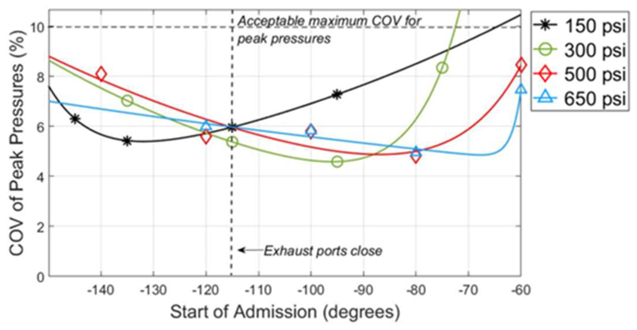
| Injection Pressure (psi) | Start of Admission (degrees) | Engine Average COV PP | Average Peak Pressures (psi) | Average Location of Peak Pressures (degrees) |
|---|---|---|---|---|
| 150 | −145 | 6.31 | 539 | 18.0 |
| −135 | 5.43 | 556 | 17.8 | |
| −115 | 5.97 | 558 | 18.2 | |
| −95 | 7.28 | 583 | 15.2 | |
| 300 | −135 | 7.03 | 527 | 18.6 |
| −115 | 5.38 | 535 | 18.0 | |
| −95 | 4.59 | 553 | 17.0 | |
| −75 | 8.35 | 565 | 18.6 | |
| 500 | −140 | 8.10 | 524 | 18.9 |
| −120 | 5.59 | 539 | 17.8 | |
| −100 | 5.80 | 522 | 18.6 | |
| −80 | 4.83 | 574 | 17.3 | |
| −60 | 8.46 | 557 | 18.6 | |
| 650 | −120 | 6.00 | 538 | 18.0 |
| −100 | 5.83 | 526 | 18.5 | |
| −80 | 4.96 | 573 | 17.5 | |
| −60 | 7.47 | 567 | 18.2 |
Disclaimer/Publisher’s Note: The statements, opinions and data contained in all publications are solely those of the individual author(s) and contributor(s) and not of MDPI and/or the editor(s). MDPI and/or the editor(s) disclaim responsibility for any injury to people or property resulting from any ideas, methods, instructions or products referred to in the content. |
© 2024 by the authors. Licensee MDPI, Basel, Switzerland. This article is an open access article distributed under the terms and conditions of the Creative Commons Attribution (CC BY) license (https://creativecommons.org/licenses/by/4.0/).
Share and Cite
Banji, T.I.; Arney, G.; Patterson, M.; Olsen, D.B. Reduction of Methane Emissions from Natural Gas Integral Compressor Engines through Fuel Injection Control. Sustainability 2024, 16, 5943. https://doi.org/10.3390/su16145943
Banji TI, Arney G, Patterson M, Olsen DB. Reduction of Methane Emissions from Natural Gas Integral Compressor Engines through Fuel Injection Control. Sustainability. 2024; 16(14):5943. https://doi.org/10.3390/su16145943
Chicago/Turabian StyleBanji, Titilope Ibukun, Gregg Arney, Mark Patterson, and Daniel B. Olsen. 2024. "Reduction of Methane Emissions from Natural Gas Integral Compressor Engines through Fuel Injection Control" Sustainability 16, no. 14: 5943. https://doi.org/10.3390/su16145943
APA StyleBanji, T. I., Arney, G., Patterson, M., & Olsen, D. B. (2024). Reduction of Methane Emissions from Natural Gas Integral Compressor Engines through Fuel Injection Control. Sustainability, 16(14), 5943. https://doi.org/10.3390/su16145943


