
Nonlinear Enhanced Control for Wind Energy Generation System-Based Permanent Magnet Synchronous Generator


Abstract
1. Introduction
- The NBA is utilized for wind system-based PMSGs to ensure MPPT, to regulate DC-link voltage, to control powers exchanged with the grid and to ensure the UPF under diverse functioning conditions;
- Improvement in response time, reference tracking precision and reduction in overshoot;
- Attainment of a high level of robustness against variations of parameters;
- The WEGS’s supervision can deal with low voltage drop conditions and model uncertainties;
- The pitch angle system proposed can track the reference value of the speed and limit the captured wind energy if wind speeds are high;
- Using the Lyapunov stability theory, some adequate conditions have been derived that guarantee the global asymptotical stability of the system.
2. Modelling of WEGS
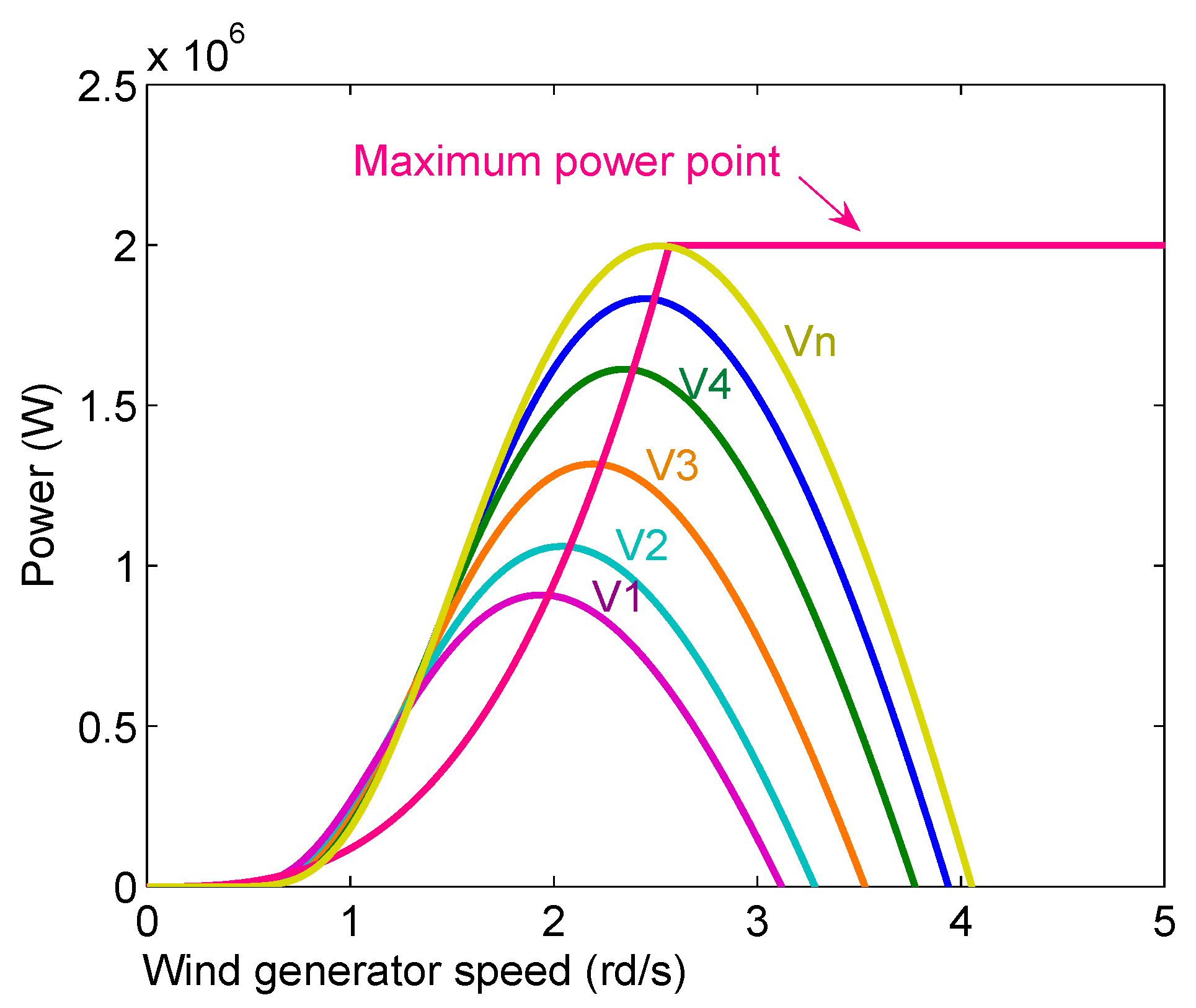
2.1. Wind Turbine (WT)
2.2. Model of Generator and B2B Two-Level Converters
- -
- Mechanical model:
- -
- Electrical model:
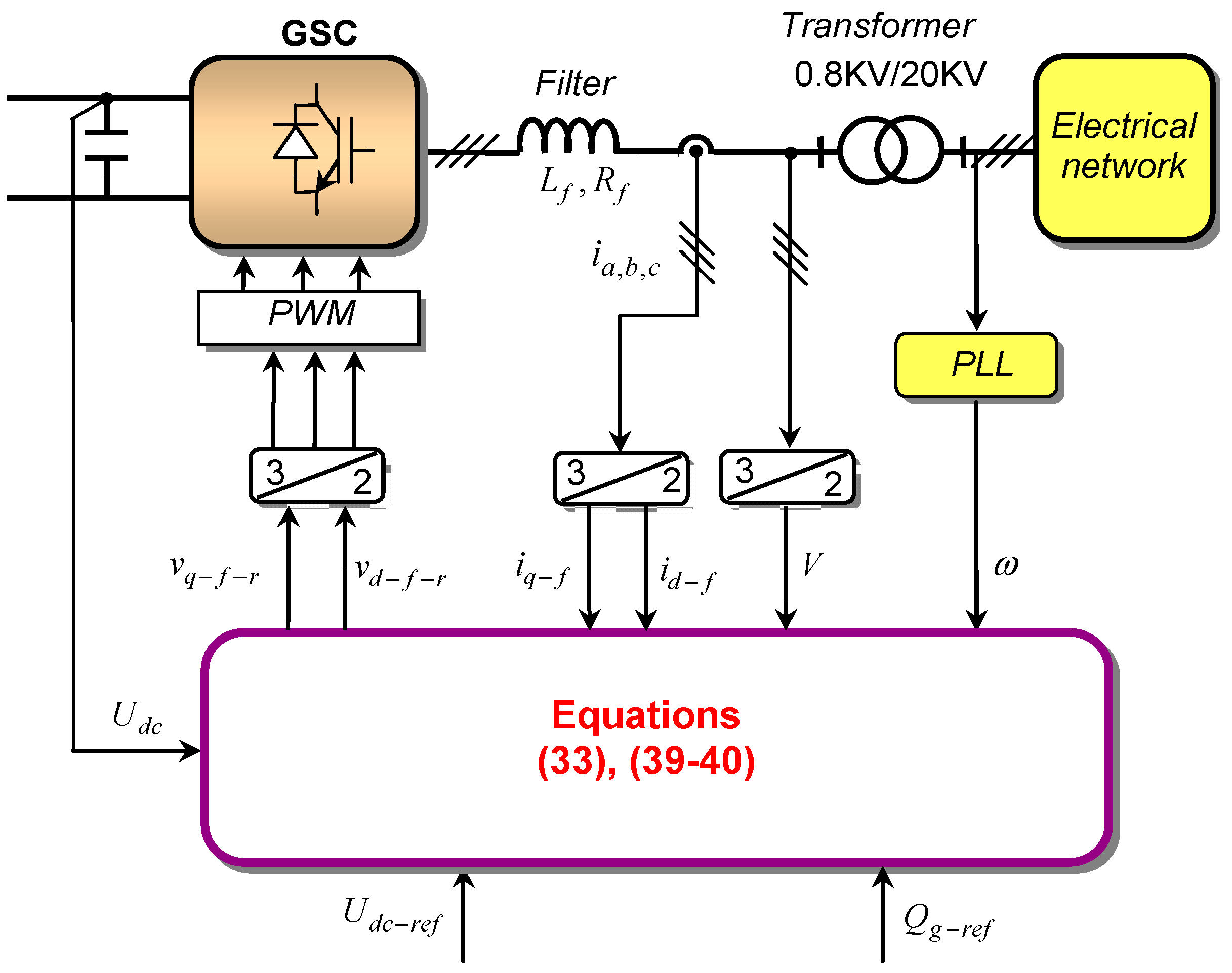
2.3. Model of GSC
3. Proposed Control of the WEGS
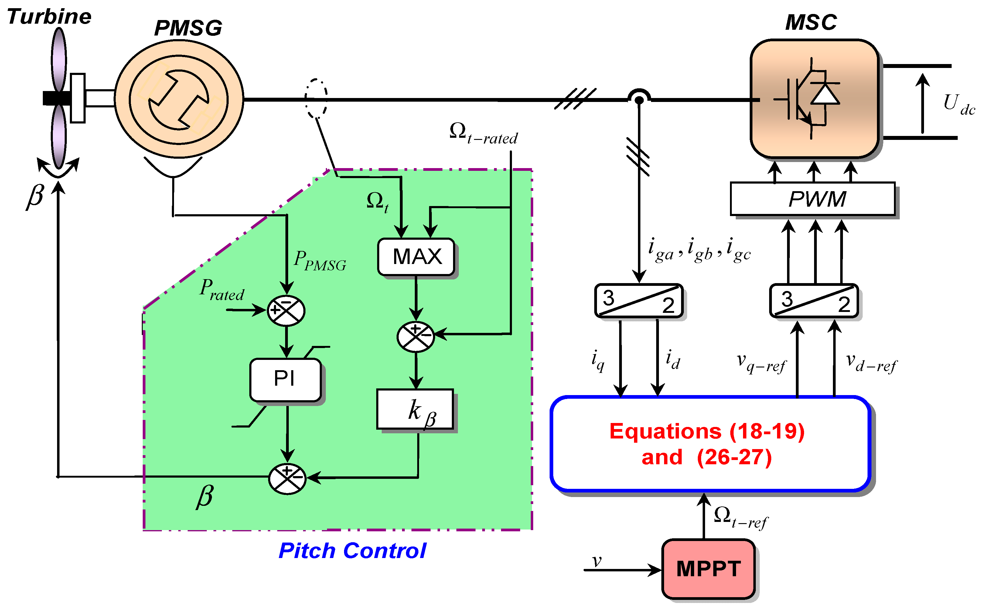
3.1. Control of MSC
3.2. Control of GSC
3.3. Global Stability Analysis of the Presented Strategy
3.4. Pitch Control Approach
4. Performance Evaluation
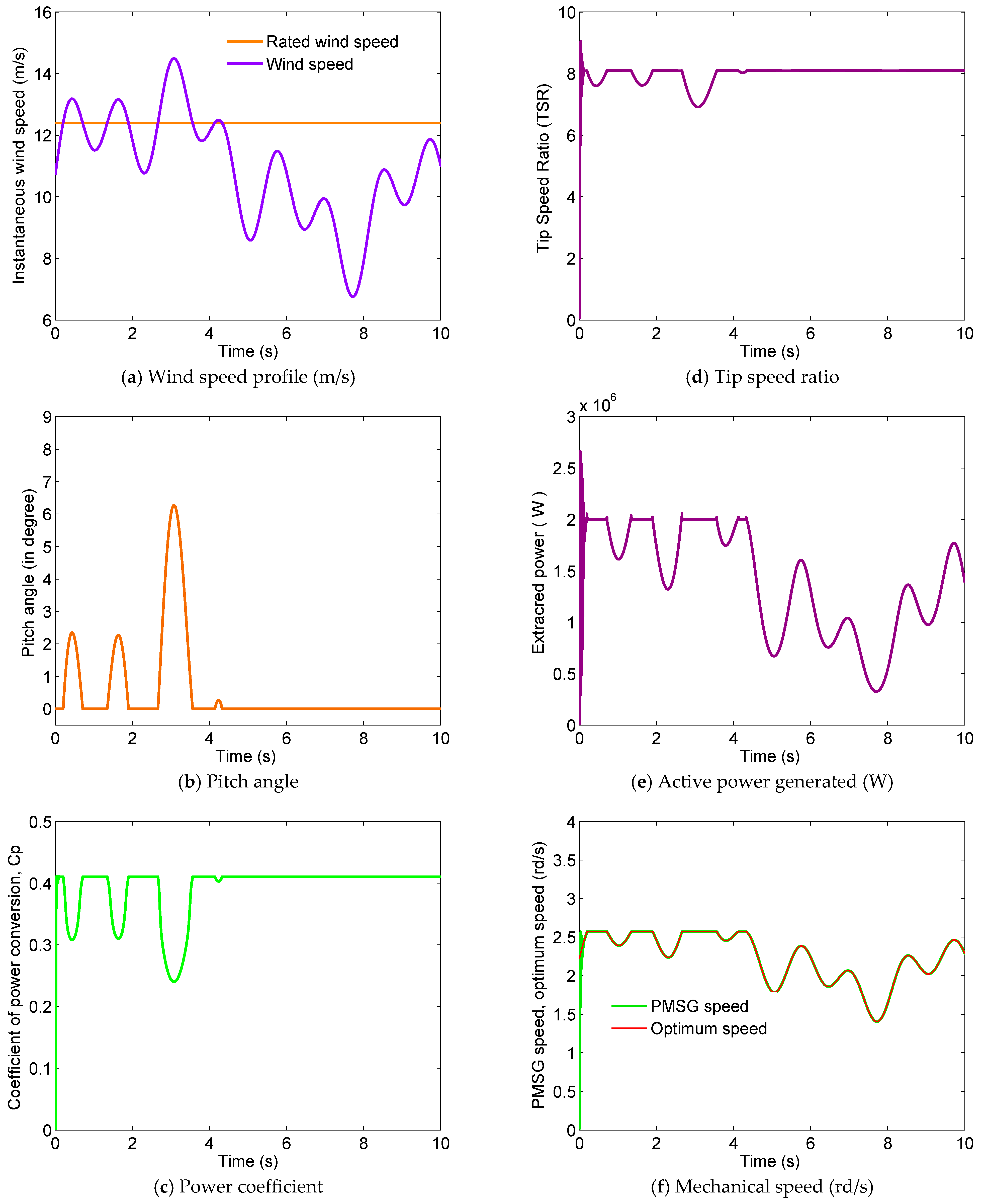
4.1. Scenario 1: Performances of the Presented Methods Using Varying Wind Speed
4.2. Scenario 2: Impact of Parameter Variations
4.3. Scenario 3: Performance of the Proposed Methods under Grid Voltage Sag Conditions
5. Conclusions
Author Contributions
Funding
Institutional Review Board Statement
Informed Consent Statement
Data Availability Statement
Conflicts of Interest
Nomenclature
| Symbol | Designation |
| Aerodynamic power of the wind turbine | |
| Air density | |
| Coefficient of power conversion | |
| Speed of the wind | |
| Ratio between the speed of the blade | |
| Radius of the WT blade | |
| Rotor angular speed | |
| Electrical rotating velocity of the PMSG | |
| Turbine’s torque | |
| Speed of the blades | |
| Pitch Angle (PA) of the blade | |
| Reference of speed | |
| Stator voltages | |
| d-q axis stator currents | |
| Stator resistance | |
| Stator reactance of the PMSG | |
| Peak flux of the PMSG | |
| Number of pole pairs | |
| Electromagnetic torque | |
| Total moment of inertia of the system | |
| Coefficient of viscous friction | |
| Grid voltage component voltages | |
| Line currents | |
| , | Filter inductance and filter resistance |
| , | Grid voltage components in the d-axis and q-axis voltage components |
| Grid voltage components in the d-axis | |
| GSC voltage components | |
| Voltage of DC link | |
| Electrical frequency | |
| Current at the input of the inverter | |
| Output current of the PMSG | |
| d-axis current and q-axis current of grid | |
| Capacitor of DC link | |
| Abbreviations | |
| WEGS | Wind Energy Generation System |
| PMSG | Permanent Magnet Synchronous Generator |
| MPPT | Maximum Power Point Tracking |
| NBA | Nonlinear Backstepping Approach |
| VC | Vector Controller |
| IG | Induction Generator |
| DFIG | Doubly Fed Induction Generator |
| BTBC | Back-to-Back Converter |
| UPF | Unity Power Factor |
| VCA | Vector Control Approach |
| LC | Linear Controller |
| PI | Proportional Integral |
| SMC | Sliding Mode Control |
References
- Shutari, H.; Ibrahim, T.; Nor, N.B.M.; Saad, N.; Tajuddin, M.F.N.; Abdulrab, H.Q. Development of a Novel Efficient Maximum Power Extraction Technique for Grid-Tied VSWT System. IEEE Access 2022, 10, 101922–101935. [Google Scholar] [CrossRef]
- Salem, A.A.; Aldin, N.A.N.; Azmy, A.M.; Abdellatif, W.S. Implementation and Validation of an Adaptive Fuzzy Logic Controller for MPPT of PMSG-Based Wind Turbines. IEEE Access 2021, 9, 165690–165707. [Google Scholar] [CrossRef]
- Mayilsamy, G.; Natesan, B.; Joo, Y.H.; Lee, S.R. Fast Terminal Synergetic Control of PMVG-Based Wind Energy Conversion System for Enhancing the Power Extraction Efficiency. Energies 2022, 15, 2774. [Google Scholar] [CrossRef]
- Osman, A.; Alsokhiry, F. Sliding Mode Control for Grid Integration of Wind Power System Based on Direct Drive PMSG. IEEE Access 2022, 10, 26567–26579. [Google Scholar] [CrossRef]
- Bakbak, A.; Altintas, M.; Ayaz, M.; Canseven, H.T.; Boztepe, M.; Akin, O.; Mese, E. PMSG-Based Dual-Port Wind-Energy Conversion System With Reduced Converter Size. IEEE Access 2021, 9, 118953–118967. [Google Scholar] [CrossRef]
- Kim, C.; Kim, W. Low-Voltage Ride-Through Coordinated Control for PMSG Wind Turbines Using De-Loaded Operation. IEEE Access 2021, 9, 66599–66606. [Google Scholar] [CrossRef]
- Shariatpanah, H.; Fadaeinedjad, R.; Rashidinejad, M. A New Model for PMSG-Based Wind Turbine with Yaw Control. IEEE Trans. Energy Convers. 2013, 28, 929–937. [Google Scholar] [CrossRef]
- Li, S.; Haskew, T.A.; Swatloski, R.P.; Gathings, W. Optimal and Direct-Current Vector Control of Direct-Driven PMSG Wind Turbines. IEEE Trans. Power Electron. 2012, 27, 2325–2337. [Google Scholar] [CrossRef]
- Trinh, D.T.; Wu, Y.K.; Pham, M.H. Adaptive Frequency Control Strategy for PMSG-Based Wind Turbines with Improved Rotor Speed Recovery. IEEE Access 2024, 12, 63853–63864. [Google Scholar] [CrossRef]
- Rajaei, A.; Mohamadian, M.; Yazdian Varjani, A. Vienna-Rectifier-Based Direct Torque Control of PMSG for Wind Energy Application. IEEE Trans. Ind. Electron. 2013, 60, 2919–2929. [Google Scholar] [CrossRef]
- Tian, Y.; Cai, B.; Liu, Y. Research on BPNN-Based SVM-DTC for Direct Drive PMSG Wind Turbine. In Proceedings of the 2021 China Automation Congress (CAC), Beijing, China, 22–24 October 2021; pp. 3098–3103. [Google Scholar] [CrossRef]
- Zhang, Z.; Wang, F.; Wang, J.; Rodríguez, J.; Kennel, R. Nonlinear Direct Control for Three-Level NPC Back-to-Back Converter PMSG Wind Turbine Systems: Experimental Assessment with FPGA. IEEE Trans. Ind. Inform. 2017, 13, 1172–1183. [Google Scholar] [CrossRef]
- Zhang, Z.; Zhao, Y.; Qiao, W.; Qu, L. A Space-Vector Modulated Sensorless Direct-Torque Control for Direct-Drive PMSG Wind Turbines. IEEE Trans. Ind. Appl. 2014, 50, 2331–2341. [Google Scholar] [CrossRef]
- Zhang, Z.; Zhao, Y.; Qiao, W.; Qu, L. A Discrete-Time Direct-Torque Control for Direct-Drive PMSG-Based Wind Energy Conversion Systems. IEEE Trans. Ind. Appl. 2015, 51, 3504–3514. [Google Scholar] [CrossRef]
- Freire, N.M.A.; Cardoso, A.J.M. A Fault-Tolerant Direct Controlled PMSG Drive for Wind Energy Conversion Systems. IEEE Trans. Ind. Electron. 2014, 61, 821–834. [Google Scholar] [CrossRef]
- Bakhtiari, F.; Nazarzadeh, J. Optimal Estimation and Tracking Control for Variable-speed Wind Turbine with PMSG. J. Mod. Power Syst. Clean Energy 2020, 8, 159–167. [Google Scholar] [CrossRef]
- Belkhier, Y.; Achour, A.; Ullah, N.; Shaw, R.N.; Farooq, Z.; Ullah, A.; Alzaed, A.N. Intelligent Energy-Based Modified Super Twisting Algorithm and Factional Order PID Control for Performance Improvement of PMSG Dedicated to Tidal Power System. IEEE Access 2021, 9, 57414–57425. [Google Scholar] [CrossRef]
- Pan, L.; Shao, C. Wind energy conversion systems analysis of PMSG on offshore wind turbine using improved SMC and extended state observer. Renew Energy 2020, 161, 149–161. [Google Scholar] [CrossRef]
- Jingfeng, M.; Aihua, W.; Guoqing, W.; Xudong, Z. Maximum power point tracking in variable speed wind turbine system via optimal torque sliding mode control strategy. In Proceedings of the 34th Chinese Control Conference (CCC), Hangzhou, China, 28–30 July 2015; pp. 7967–7971. [Google Scholar]
- Wang, G.; Wai, R.; Liao, Y. Design of backstepping power control for grid-side converter of voltage source converter-based high-voltage dc wind power generation system. IET Renew. Power Gener. 2013, 7, 118–133. [Google Scholar] [CrossRef]
- Khan, N.; Rahman, S.F.; Hinchey, M.J.; Rahman, M.A. Adaptive Backstepping Based Maximum Power Point Tracking Control For a Variable Speed Marine Current Energy Conversion System. In Proceedings of the IEEE Canadian Conference of Electrical and Computer Engineering (CCECE), Regina, SK, Canada, 5–8 May 2013; pp. 1–5. [Google Scholar] [CrossRef]
- Kim, K.H.; Jeung, Y.C.; Lee, D.C.; Kim, H.G. LVRT scheme of PMSG wind power systems based on feedback linearization. IEEE Trans. Power Electron. 2012, 27, 2376–2384. [Google Scholar] [CrossRef]
- Nasiri, M.; Milimonfared, J.; Fathi, S.H. Robust control of PMSG based wind turbine under grid fault conditions. Indian J. Sci. Technol. 2015, 8, 1. [Google Scholar] [CrossRef]
- Mozayan, S.M.; Saad, M.; Vahedi, H.; Fortin-Blanchette, H.; Soltani, M. Sliding mode control of PMSG wind turbine based on enhanced exponential reaching law. IEEE Trans. Ind. Electron. 2016, 63, 6148–6159. [Google Scholar] [CrossRef]
- Zheng, X.M.; Feng, Y.; Han, F.L.; Yu, X.H. Integral-type terminal sliding-mode control for grid-side converter in wind energy conversion systems. IEEE Trans. Ind. Electron. 2019, 66, 3702–3711. [Google Scholar] [CrossRef]
- Errouissi, R.; Al-Durra, A. A novel PI-type sliding surface for PMSG-based wind turbine with improved transient performance. IEEE Trans. Energy Convers. 2018, 33, 834–844. [Google Scholar] [CrossRef]
- Errami, Y.; Hilal, M.; Benchagra, M.; Ouassaid, M.; Maaroufi, M. Nonlinear control of MPPT and grid connected for variable speed wind energy conversion system based on the PMSG. J. Theor. Appl. Inf. Technol. 2012, 39, 204–217. [Google Scholar]
- Hilal, M.; Benchagra, M.; Errami, Y.; Maaroufi, M.; Ouassaid, M. Maximum power tracking of wind turbine based on doubly fed induction generator. Int. Rev. Model. Simul. 2011, 4, 2255–2263. [Google Scholar]
- Hossain, M.D.I.; Abido, M.A. Positive-Negative Sequence Current Controller for LVRT Improvement of Wind Farms Integrated MMC-HVDC Network. IEEE Access 2020, 8, 193314–193339. [Google Scholar] [CrossRef]
- Nguyen, H.T.; Al-Sumaiti, A.S.; Al Hosani, K.; El Moursi, M.S. Multifunctional Control of Wind-Turbine Based Nano-Grid Connected to Distorted Utility-Grid. IEEE Trans. Power Syst. 2022, 37, 576–589. [Google Scholar] [CrossRef]
- Errami, Y.; Ouassaid, M.; Maaroufi, M. Variable structure control for permanent magnet synchronous generator based wind energy conversion system operating under different grid conditions. In Proceedings of the 2nd World Conference on Complex Systems, WCCS 2014, Agadir, Morocco, 10–12 November 2014; pp. 340–345. [Google Scholar] [CrossRef]
- Evangelista, C.; Fernando, V.; Paul, P. Active and reactive power control for wind turbine based on a MIMO 2-sliding mode algorithm with variable gains. IEEE Trans. Energy Convers. 2013, 28, 682–689. [Google Scholar] [CrossRef]
- Thapa, K.B.; Jayasawal, K. Pitch Control Scheme for Rapid Active Power Control of a PMSG-Based Wind Power Plant. IEEE Trans. Ind. Appl. 2020, 56, 6756–6766. [Google Scholar] [CrossRef]


| Parameter | Value |
|---|---|
| , rated power | 2 (MW) |
| , rated mechanical speed | 2.57 (rd/s) |
| , stator resistance | 0.008 (Ω) |
| , stator d-axis inductance | 0.0003 (H) |
| , flux density | 3.86 (wb) |
| , pole pairs | 60 |
| Parameter | Value |
|---|---|
| , air density | 1.08 kg/m3 |
| , area swept by blades | 4775.94 m2 |
| , base wind speed | 12.4 m/s |
Disclaimer/Publisher’s Note: The statements, opinions and data contained in all publications are solely those of the individual author(s) and contributor(s) and not of MDPI and/or the editor(s). MDPI and/or the editor(s) disclaim responsibility for any injury to people or property resulting from any ideas, methods, instructions or products referred to in the content. |
© 2024 by the authors. Licensee MDPI, Basel, Switzerland. This article is an open access article distributed under the terms and conditions of the Creative Commons Attribution (CC BY) license (https://creativecommons.org/licenses/by/4.0/).
Share and Cite
Errami, Y.; Obbadi, A.; Sahnoun, S.; Aoutoul, M. Nonlinear Enhanced Control for Wind Energy Generation System-Based Permanent Magnet Synchronous Generator. Sustainability 2024, 16, 7374. https://doi.org/10.3390/su16177374
Errami Y, Obbadi A, Sahnoun S, Aoutoul M. Nonlinear Enhanced Control for Wind Energy Generation System-Based Permanent Magnet Synchronous Generator. Sustainability. 2024; 16(17):7374. https://doi.org/10.3390/su16177374
Chicago/Turabian StyleErrami, Youssef, Abdellatif Obbadi, Smail Sahnoun, and Mohssin Aoutoul. 2024. "Nonlinear Enhanced Control for Wind Energy Generation System-Based Permanent Magnet Synchronous Generator" Sustainability 16, no. 17: 7374. https://doi.org/10.3390/su16177374
APA StyleErrami, Y., Obbadi, A., Sahnoun, S., & Aoutoul, M. (2024). Nonlinear Enhanced Control for Wind Energy Generation System-Based Permanent Magnet Synchronous Generator. Sustainability, 16(17), 7374. https://doi.org/10.3390/su16177374