
Thermoelectric Generator Applications in Buildings: A Review


Abstract
1. Introduction
2. Methodology
3. Thermoelectricity and Thermoelectric Generators
4. Case Studies of TEG Installations
4.1. TEG Applications in the Building Envelope
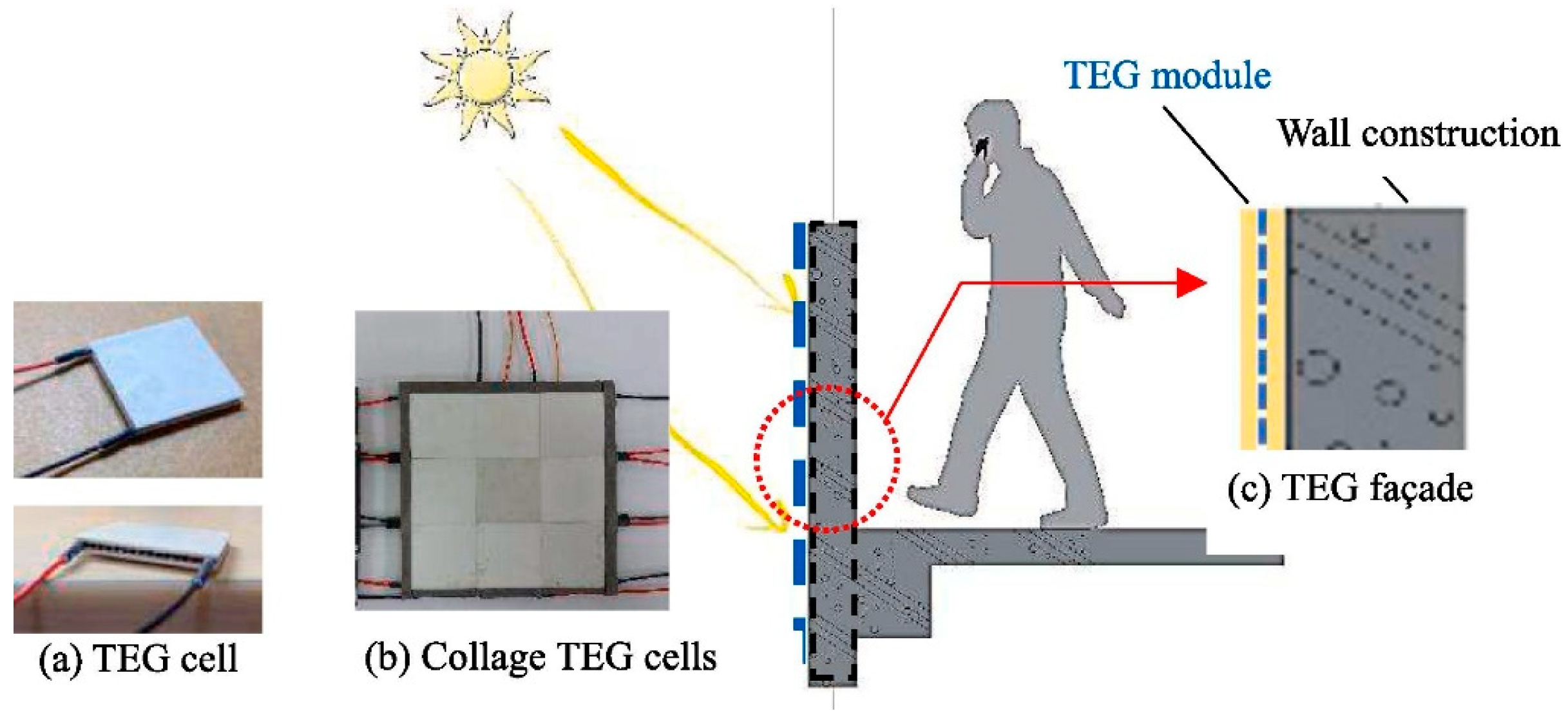
4.1.1. Façade
4.1.2. Walls
4.1.3. Windows
4.1.4. Roofs
4.2. Non-Integrated Thermoelectric Generator Applications
4.2.1. Energy Harvesting from Waste Heat or Temperature Gradients in Buildings
4.2.2. HVAC Systems
5. Discussions and Future Research Directions
Future Research Directions
6. Conclusions
Author Contributions
Funding
Institutional Review Board Statement
Informed Consent Statement
Data Availability Statement
Acknowledgments
Conflicts of Interest
Abbreviations
| IEA | International Energy Agency |
| TED | thermoelectric device |
| TEM | thermoelectric module |
| TEG | thermoelectric generator |
| TEC | thermoelectric cooling |
| THE | thermoelectric heating |
| TEV | thermoelectric ventilation |
| TCHU | thermoelectric cooling and heating unit |
| ABE | active building envelope |
| HVAC | heating, ventilation, and air conditioning |
| VATE | ventilated active thermoelectric envelope |
| RSC-TEC | radioactive sky cooling-assisted thermoelectric cooling |
| TEC-RSC | thermoelectric and radiative sky cooling |
| PCMs | phase change materials |
| SVF | solar ventilation façade |
| TEHP | thermoelectric harvesting panel |
| CW | conventional wall |
| BIPV | building-integrated photovoltaic panel |
| STEW | solar thermoelectric wall |
| LCOE | levelized cost of electricity |
| TPWSN | thermoelectric-powered wireless sensor network system |
| LCPV/T-TEG | low-concentration photovoltaic/thermal–thermoelectric generator |
| CPV-TEG | concentrated photovoltaic–thermoelectric generator |
References
- IEA. Tracking Clean Energy Progress 2023; IEA: Paris, France, 2023. Available online: https://www.iea.org/reports/tracking-clean-energy-progress-2023 (accessed on 7 July 2023).
- Camarasa, C.; Mata, É.; Navarro, J.P.J.; Reyna, J.; Bezerra, P.; Angelkorte, G.B.; Feng, W.; Filippidou, F.; Forthuber, S.; Harris, C.; et al. A global comparison of building decarbonization scenarios by 2050 towards 1.5–2 °C targets. Nat. Commun. 2022, 13, 3077. [Google Scholar] [CrossRef]
- Luo, Y.; Zhang, L.; Liu, Z.; Yu, J.; Xu, X.; Su, X. Towards net zero energy building: The application potential and adaptability of photovoltaic-thermoelectric-battery wall system. Appl. Energy 2020, 258, 114066. [Google Scholar] [CrossRef]
- IPCC. AR6 Synthesis Report: Climate Change 2023-Working Group III–Mitigation of Climate Change-Chapter 9-Buildings. 2023. Available online: https://www.ipcc.ch/report/sixth-assessment-report-cycle/ (accessed on 20 March 2023).
- UNEP. Global Status Report for Buildings and Construction. 2024. Available online: https://www.unep.org/resources/report/global-status-report-buildings-and-construction (accessed on 7 March 2024).
- Xu, X.; Dessel, S.V.; Messac, A. Study of the performance of thermoelectric modules for use in active building envelopes. Build. Environ. 2007, 42, 1489–1502. [Google Scholar] [CrossRef]
- Xu, X.; Van Dessel, S. Evaluation of a prototype active building envelope window-system. Energy Build. 2008, 40, 168–174. [Google Scholar] [CrossRef]
- Gillott, M.; Jiang, L.; Riffat, S. An investigation of thermoelectric cooling devices for small-scale space conditioning applications in buildings. Int. J. Energy Res. 2010, 34, 776–786. [Google Scholar] [CrossRef]
- Ibáñez-Puy, M.; Martín-Gómez, C.; Vidaurre-Arbizu, M.; Sacristán-Fernández, J.A. Theoretical design of an active façade system with peltier cells. Energy Procedia 2014, 61, 700–703. [Google Scholar] [CrossRef]
- Liu, Z.; Zhang, L.; Gong, G.; Han, T. Experimental evaluation of an active solar thermoelectric radiant wall system. Energy Convers. Manag. 2015, 94, 253–260. [Google Scholar] [CrossRef]
- Ibañez-Puy, M.; Martín-Gómez, C.; Bermejo-Busto, J.; Sacristán, J.A.; Ibañez-Puy, E. Ventilated active thermoelectric envelope (VATE): Analysis of its energy performance when integrated in a building. Energy Build. 2018, 158, 1586–1592. [Google Scholar] [CrossRef]
- Zuazua-Ros, A.; Martín-Gómez, C.; Ibáñez-Puy, E.; Vidaurre-Arbizu, M.; Ibáñez-Puy, M. Design, assembly and energy performance of a ventilated active thermoelectric envelope module for heating. Energy Build. 2018, 176, 371–379. [Google Scholar] [CrossRef]
- Martín-Gómez, C.; Zuazua-Ros, A.; De Lersundi, K.D.V.; Saiz-Ezquerra, B.S.; Ibáñez-Puy, M. Integration development of a ventilated active thermoelectric envelope (VATE): Constructive optimization and thermal performance. Energy Build. 2021, 231, 110593. [Google Scholar] [CrossRef]
- Zhao, D.; Yin, X.; Xu, J.; Tan, G.; Yang, R. Radiative sky cooling-assisted thermoelectric cooling system for building applications. Energy 2020, 190, 116322. [Google Scholar] [CrossRef]
- Su, X.; Zhang, L.; Liu, Z.; Luo, Y.; Chen, D.; Li, W. Performance evaluation of a novel building envelope integrated with thermoelectric cooler and radiative sky cooler. Renew. Energy 2021, 171, 1061–1078. [Google Scholar] [CrossRef]
- Shittu, S.; Li, G.; Xuan, Q.; Zhao, X.; Ma, X.; Cui, Y. Electrical and mechanical analysis of a segmented solar thermoelectric generator under non-uniform heat flux. Energy 2020, 199, 117433. [Google Scholar] [CrossRef]
- Jaziri, N.; Boughamoura, A.; Müller, J.; Mezghani, B.; Tounsi, F.; Ismail, M. A comprehensive review of thermoelectric generators: Technologies and common applications. Energy Rep. 2020, 6, 264–287. [Google Scholar] [CrossRef]
- Atouei, S.A.; Rezania, A.; Ranjbar, A.A.; Rosendahl, L.A. Protection and thermal management of thermoelectric generator system using phase change materials: An experimental investigation. Energy 2018, 156, 311–318. [Google Scholar] [CrossRef]
- Jouhara, H.; Żabnieńska-Góra, A.; Khordehgah, N.; Doraghi, Q.; Ahmad, L.; Norman, L.; Axcell, B.; Wrobel, L.; Dai, S. Thermoelectric Generator (TEG) Technologies and Applications. Int. J. Thermofluids 2021, 9, 100063. [Google Scholar] [CrossRef]
- Zoui, M.A.; Bentouba, S.; Stocholm, J.G.; Bourouis, M. A Review on Thermoelectric Generators: Progress and Applications. Energies 2020, 13, 06. [Google Scholar] [CrossRef]
- Ando Junior, O.H.; Maran, A.L.O.; Henao, N.C. A Review of the Development and Applications of Thermoelectric Microgenerators for Energy Harvesting. Renew. Sustain. Energy Rev. 2018, 91, 376–393. [Google Scholar] [CrossRef]
- Karthick, K.; Suresh, S.; Hussain, M.M.M.D.; Ali, H.M.; Kumar, C.S.S. Evaluation of Solar Thermal System Configurations for Thermoelectric Generator Applications: A Critical Review. Sol. Energy 2019, 188, 111–142. [Google Scholar] [CrossRef]
- Kandi, R.P.; Sudharmini, M.M.; Suryan, A.; Nižetić, S. State of the Art and Future Prospects for TEG-PCM Systems: A Review. Energy Sustain. Dev. 2023, 74, 328–348. [Google Scholar] [CrossRef]
- Sanin-Villa, D. Recent Developments in Thermoelectric Generation: A Review. Sustainability 2022, 14, 16821. [Google Scholar] [CrossRef]
- Bhakta, S.; Kundu, B. A Review of Thermoelectric Generators in Automobile Waste Heat Recovery Systems for Improving Energy Utilization. Energies 2024, 17, 1016. [Google Scholar] [CrossRef]
- Jabri, M.; Masoumi, S.; Sajadirad, F.; West, R.P.; Pakdel, A. Thermoelectric Energy Conversion in Buildings. Mater. Today Energy 2023, 32, 101257. [Google Scholar] [CrossRef]
- He, Z.; Zuazua-Ros, A.; Martín-Gómez, C. Thermoelectric System Applications in Buildings: A Review of Key Factors and Control Methods. J. Build. Eng. 2023, 78, 107658. [Google Scholar] [CrossRef]
- Seebeck, T.J. Ueber die magnetische polarisation der metalle und erze durch temperaturdifferenz. Ann. Phys. 1826, 82, 253–286. [Google Scholar] [CrossRef]
- Champier, D. Thermoelectric generators: A review of applications. Energy Convers. Manag. 2017, 140, 167–181. [Google Scholar] [CrossRef]
- Peltier, J. Nouvelle experiences sur la caloricité des courants électriques. In Annales de Chimie et Physique; LVI: Paris, France, 1834; pp. 371–387. [Google Scholar]
- Thomson, W. On the dynamical theory of heat transfer. Trans. R. Soc. Edinb. 1852, 3, 91–98. [Google Scholar] [CrossRef]
- Altenkirch, E. Über den nutzeffekt der thermosäule. Phys. Z. 1909, 10, 12. [Google Scholar]
- Hendricks, T.; Choate, W.T. Engineering Scoping Study of Thermoelectric Generator Systems for Industrial Waste Heat Recovery; Pacific Northwest National Lab: Richland, DC, USA, 2006. [Google Scholar]
- Roy, C. Manufacture of Thermoelectric Devices. U.S. Patent 2980746A, 18 April 1961. [Google Scholar]
- Martín-Gómez, C.; Ibáñez-Puy, M.; Sacristán-Fernández, J.A. Construction of an Active Facade Envelope with Peltier Cells: 39. IAHS (The International Association for Housing Science); Politecnico di Milano: Milano, Italy, 2013. [Google Scholar]
- Irshad, K.; Habib, K.; Saidur, R.; Kareem, M.W.; Saha, B.B. Study of Thermoelectric and Photovoltaic Facade System for Energy Efficient Building Development: A Review. J. Clean. Prod. 2019, 209, 1376–1395. [Google Scholar] [CrossRef]
- Aksamija, A.; Aksamija, Z.; Counihan, C.; Brown, D.; Upadhyaya, M. Experimental Study of Operating Conditions and Integration of Thermoelectric Materials in Facade Systems. Front. Energy Res. 2019, 7, 6. [Google Scholar] [CrossRef]
- Blum, T.; Carrigan, S.; Platzek, D.; Kornadt, O. Evaluation of the Energy Efficiency of an Active Thermoelectric Façade. Energy Build. 2023, 292, 113128. [Google Scholar] [CrossRef]
- Huang, X.Y.; He, J.W.; Huang, Y.X.; Cai, Y.; Wang, W.W.; Zhao, F.Y. Numerical analysis of solar ventilated façade integrated thermoelectric energy harvesting panel for simultaneous building thermal insulation and power generation. J. Build. Eng. 2023, 76, 107304. [Google Scholar] [CrossRef]
- Win, S.L.Y.; Liao, C.T.; Chang, H.Y.; Lai, C.M. Experimental observations on electricity generation and thermal characteristics of TEG façades. Energy Build. 2023, 294, 113225. [Google Scholar] [CrossRef]
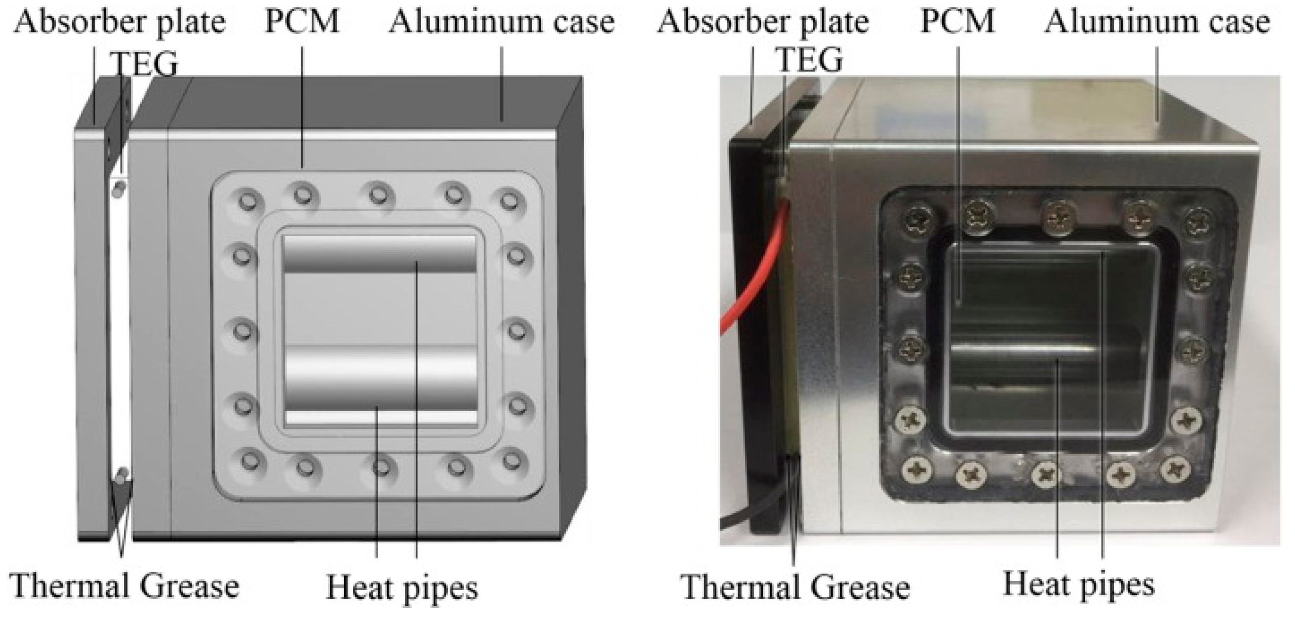
- Ko, J.; Jeong, J.W. Annual performance evaluation of thermoelectric generator-assisted building-integrated photovoltaic system with phase change material. Renew. Sustain. Energy Rev. 2021, 145, 111085. [Google Scholar] [CrossRef] [PubMed]
- Kang, Y.K.; Joung, J.; Kim, M.; Jeong, J.W. Energy Impact of Heat Pipe-Assisted Microencapsulated Phase Change Material Heat Sink for Photovoltaic and Thermoelectric Generator Hybrid Panel. Renew. Energy 2023, 207, 298–308. [Google Scholar] [CrossRef]
- Kang, Y.K.; Joung, J.; Kim, S.; Park, J.; Jeong, J.W. Design of a Thermoelectric Generator-Assisted Photovoltaic Panel Hybrid Harvester Using Microencapsulate Phase Change Material. J. Build. Eng. 2024, 87, 109110. [Google Scholar] [CrossRef]
- Hong, B.H.; Huang, X.Y.; He, J.W.; Cai, Y.; Wang, W.W.; Zhao, F.Y. Round-the-clock performance of solar thermoelectric wall with phase change material in subtropical climate: Critical analysis and parametric investigations. Energy 2023, 272, 127128. [Google Scholar] [CrossRef]
- Indab, M.B.L.; Ng, J.A.T.; Reyeg, L.A.F.P.; Tuppil, R.A.G.; Umali, R.; Manuel, M.C.E.; Cruz, J.C.D.; Tud, R.C. Design, fabrication, and testing of thermoelectric generators integrated on a residential window frame. In Proceedings of the 2021 IEEE International Conference on Automatic Control & Intelligent Systems (I2CACIS), Shah Alam, Malaysia, 26 June 2021; IEEE: Shah Alam, Malaysia, 2021; pp. 197–202. [Google Scholar]
- Lin, Q.; Chen, Y.C.; Chen, F.; DeGanyar, T.; Yin, H. Design and experiments of a thermoelectric-powered wireless sensor network platform for smart building envelope. Appl. Energy 2022, 305, 117791. [Google Scholar] [CrossRef]
- Ilahi, T.; Abid, M.; Ilahi, T. Design and analysis of thermoelectric material based roof top energy harvesting system for Pakistan. In Proceedings of the 2015 Power Generation System and Renewable Energy Technologies (PGSRET), Islamabad, Pakistan, 10–11 June 2015; IEEE: Islamabad, Pakistan, 2015; pp. 1–3. [Google Scholar]
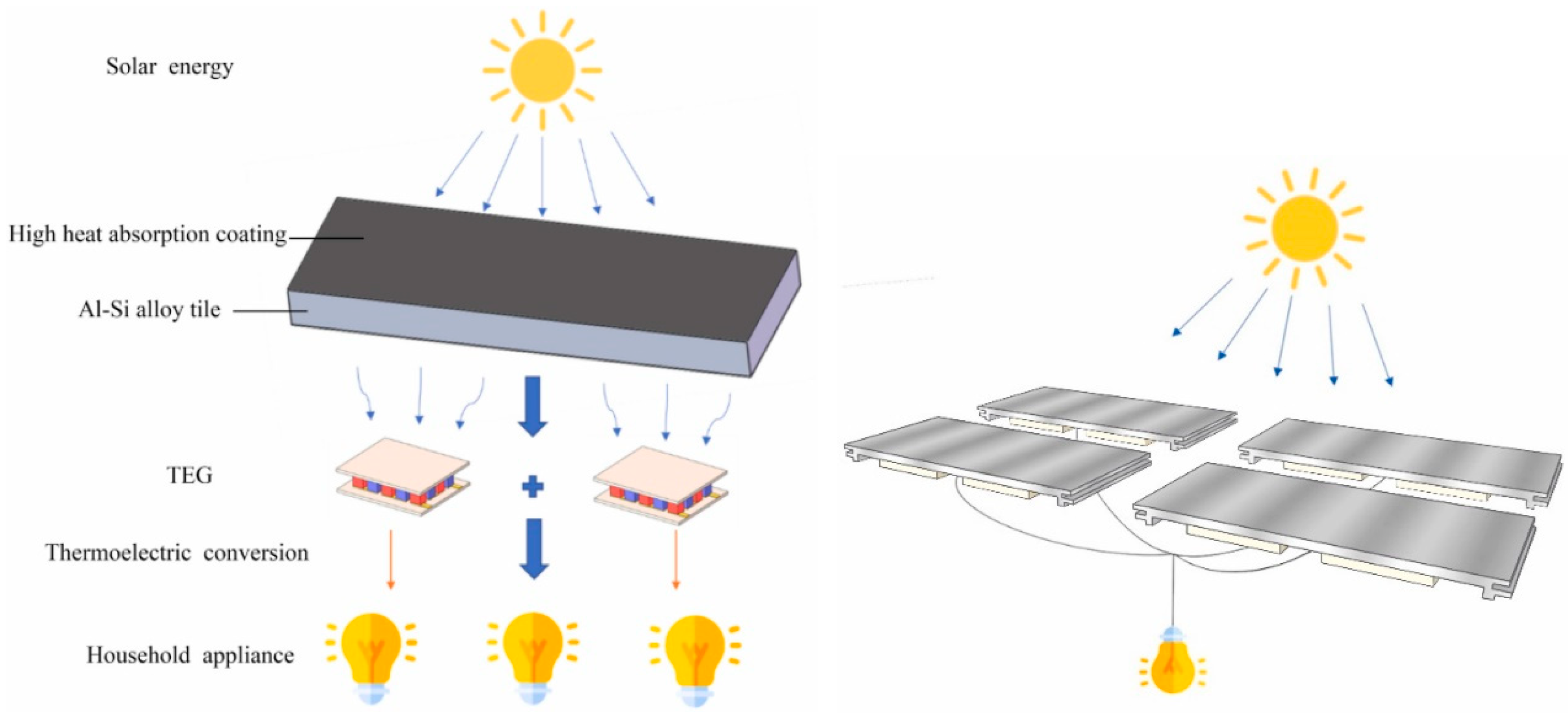
- Tong, Y.; Yang, W. Numerical analysis and experimental study on the thermoelectric characteristics of the Al–Si alloy used for building energy storage tile. Renew. Energy 2022, 200, 1447–1457. [Google Scholar] [CrossRef]
- Wang, W.; Cionca, V.; Wang, N.; Hayes, M.; O’Flynn, B.; O’Mathuna, C. Thermoelectric energy harvesting for building energy management wireless sensor networks. Int. J. Distrib. Sens. Netw. 2013, 9, 232438. [Google Scholar] [CrossRef]
- Al Musleh, M.; Topriska, E.V.; Jenkins, D.; Owens, E. Thermoelectric generator characterization at extra-low-temperature difference for building applications in extreme hot climates: Experimental and numerical study. Energy Build. 2020, 225, 110285. [Google Scholar] [CrossRef]
- Byon, Y.S.; Jeong, J.W. Annual energy harvesting performance of a phase change material-integrated thermoelectric power generation block in building walls. Energy Build. 2020, 228, 110470. [Google Scholar] [CrossRef]
- Ko, J.; Cheon, S.Y.; Kang, Y.K.; Jeong, J.W. Design of a thermoelectric generator-assisted energy harvesting block considering melting temperature of phase change materials. Renew. Energy 2022, 193, 89–112. [Google Scholar] [CrossRef]
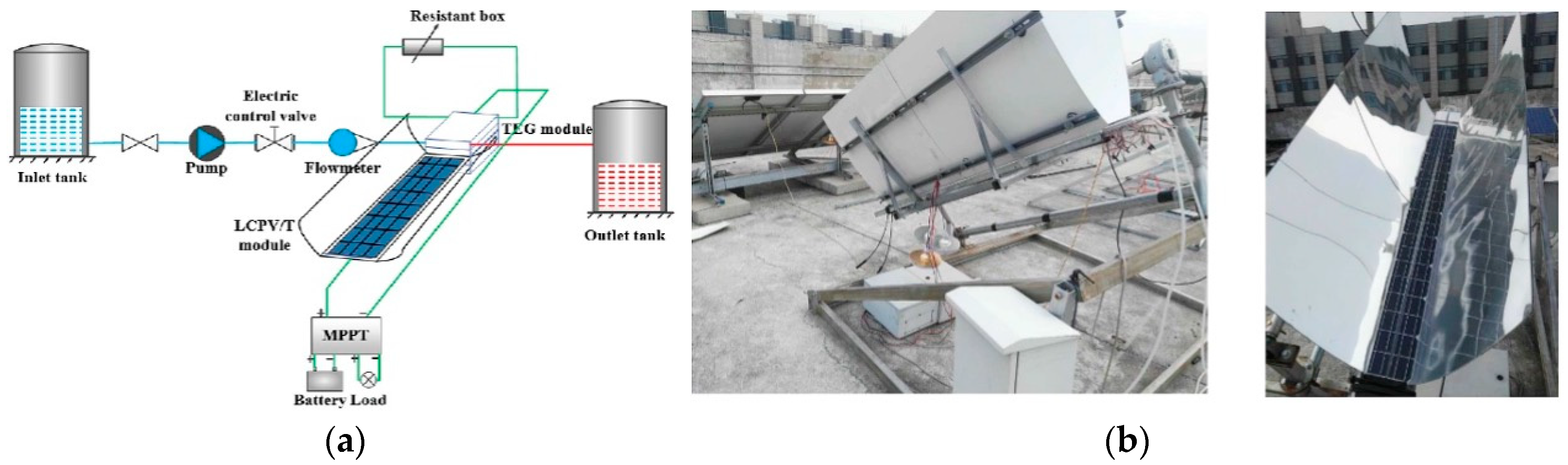
- Chen, H.; Huang, J.; Zhang, H.; Liang, K.; Liu, H.; Liang, S. Experimental investigation of a novel low concentrating photovoltaic/thermal–thermoelectric generator hybrid system. Energy 2019, 166, 83–95. [Google Scholar] [CrossRef]
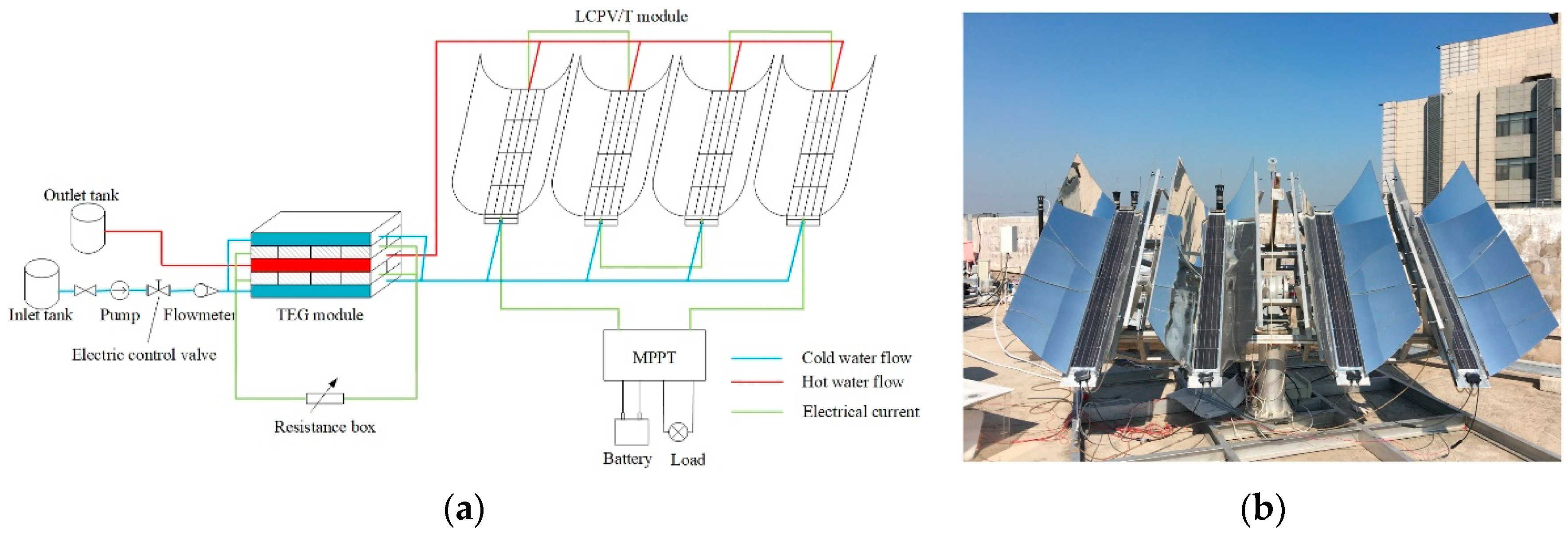
- Zhang, H.; Yue, H.; Huang, J.; Liang, K.; Chen, H. Experimental studies on a low concentrating photovoltaic/thermal (LCPV/T) collector with a thermoelectric generator (TEG) module. Renew. Energy 2021, 171, 1026–1040. [Google Scholar] [CrossRef]
- Lv, S.; He, W.; Hu, Z.; Liu, M.; Qin, M.; Shen, S.; Gong, W. High-performance terrestrial solar thermoelectric generators without optical concentration for residential and commercial rooftops. Energy Convers. Manag. 2019, 196, 69–76. [Google Scholar] [CrossRef]
- Ji, Y.; Lv, S. Experimental and numerical investigation on a radiative cooling driving thermoelectric generator system. Energy 2023, 268, 126734. [Google Scholar] [CrossRef]
- Cai, Y.; Wang, W.W.; Liu, C.W.; Ding, W.T.; Liu, D.; Zhao, F.Y. Performance evaluation of a thermoelectric ventilation system driven by the concentrated photovoltaic thermoelectric generators for green building operations. Renew. Energy 2020, 147, 1565–1583. [Google Scholar] [CrossRef]


| Integration Type | Study/Reference | Conversion Efficiency | Observations |
|---|---|---|---|
| Integrated | Huang et al. (2023) [39] | 0.0324% | Very low efficiency in solar ventilated façade application; requires significant improvement for practical use. |
| Integrated | Win et al. (2023) [40] | Up to 100.0 mW/m2 (power density); specific conversion efficiency not calculated. | High power density on reinforced concrete façades; highlights potential for structural materials. |
| Integrated | Ko and Jeong (2023) [41] | 1.09% annual energy increase; potential overall increase of 4.47% with PCM optimization. | Moderate efficiency increase in BIPV-TEG-PCM systems; efficiency varies with seasons, optimized for winter. |
| Integrated | Hong et al. (2023) [42] | <25% energy conversion; specific efficiency depends on solar radiance and PCM performance. | Low energy conversion efficiency in solar thermoelectric walls with PCM; practical deployment needs improvement. |
| Integrated | Lin et al. (2023) [45] | 1.5 mW power output under 6 °C temperature difference; specific conversion efficiency not calculated. | Limited power generation in window frame applications; useful for low-power smart sensor applications. |
| Integrated | Tong and Yang (2022) [48] | 7.17% electrical efficiency under 1032 W/m2 solar irradiance; 5.2% under 1021 W/m2 solar irradiance. | Relatively high efficiency for roof-based STEG systems; promising for specific high solar irradiance regions. |
| Non-Integrated | Wang et al. (2013) [49] | 25% end-to-end conversion efficiency for waste heat recovery in wireless sensor networks. | High efficiency in waste heat recovery; effective for building management systems. |
| Non-Integrated | Al Musleh et al. (2023) [50] | 5.2% peak electrical efficiency; 22 mW output at 10 °C temperature difference. | Moderate efficiency for energy harvesting blocks in extreme hot climates; effective under low-temperature gradients. |
| Non-Integrated | Byon and Jeong (2023) [51] | 2.1 kWh/m2 annual energy generation; average power output of 0.03 W; average voltage of 0.3 V. | Moderate power generation in PCM-integrated blocks; continuous energy harvesting potential from waste heat. |
| Non-Integrated | Ko et al. (2023) [52] | 46.5% annual energy increase with optimized PCM (26 °C melting temperature) compared to other configurations. | Significant efficiency gain with proper PCM selection; efficiency is highly dependent on local climate conditions. |
| Non-Integrated | Chen et al. (2023) [53] | 57.03% overall system efficiency (thermal efficiency 45.0%, PV efficiency 11.8%, TEG efficiency 0.23%). | Very high overall efficiency in LCPV/T-TEG hybrid system; TEG contributes modestly compared to other components. |
| Non-Integrated | Zhang et al. (2023) [54] | 14.34% (PV efficiency); TEG contributed 0.385% of total energy output in optimized LCPV/T-TEG system. | High PV efficiency; TEG plays a supplementary role with minimal contribution. |
| Non-Integrated | Lv et al. (2023) [55] | 7.17% electrical efficiency under 1032 W/m2 solar irradiance; 5.2% under 1021 W/m2 solar irradiance. | High efficiency for roof-based systems; concerns about long-term material stability under real-world conditions. |
| Non-Integrated | Ji and Lv (2023) [56] | Low efficiency; open circuit voltage of 87 mV with a 2.3–3.2 °C temperature difference. | Low efficiency in RSC-TEG systems; suitable for small temperature gradients but needs significant optimization. |
| Non-Integrated | Cai et al. (2023) [57] | 1.67% energy efficiency in winter heating mode; 0.24% exergy efficiency. | Low efficiency in CPV-TEG systems for HVAC; better performance in winter than summer. |
| Application | TEG Form | TEG Design | Output Power | Key Findings | Ref |
|---|---|---|---|---|---|
| Structural and Non-Structural Façades | Integrated into various structural/non-structural façades | TEG modules on RC walls, hollow copper curtain walls, cement mortar blocks, aluminum honeycomb structures | 100.0 mW/m2 (RC wall), 48.0 mW/m2 (curtain wall), 62.3 mW/m2 (mortar block), 61.3 mW/m² (PCM honeycomb board) | High power generation for structural façades; non-structural façades show significant power with balanced energy and thermal management | [39] |
| Solar Ventilated Façade (SVF-TEHP) | Integrated into Solar Ventilated Façade | TEHP in solar ventilated channels; varied channel width and thermoelectric arm lengths | 0.37 mW at 900 W/m2 (SVF-TEHP), 0.231 mW at 70 mm width, 0.640 mW at 8 mm arm length | <1 year payback; increased interior wall temperature at high intensities; channel width and arm length impact performance | [40] |
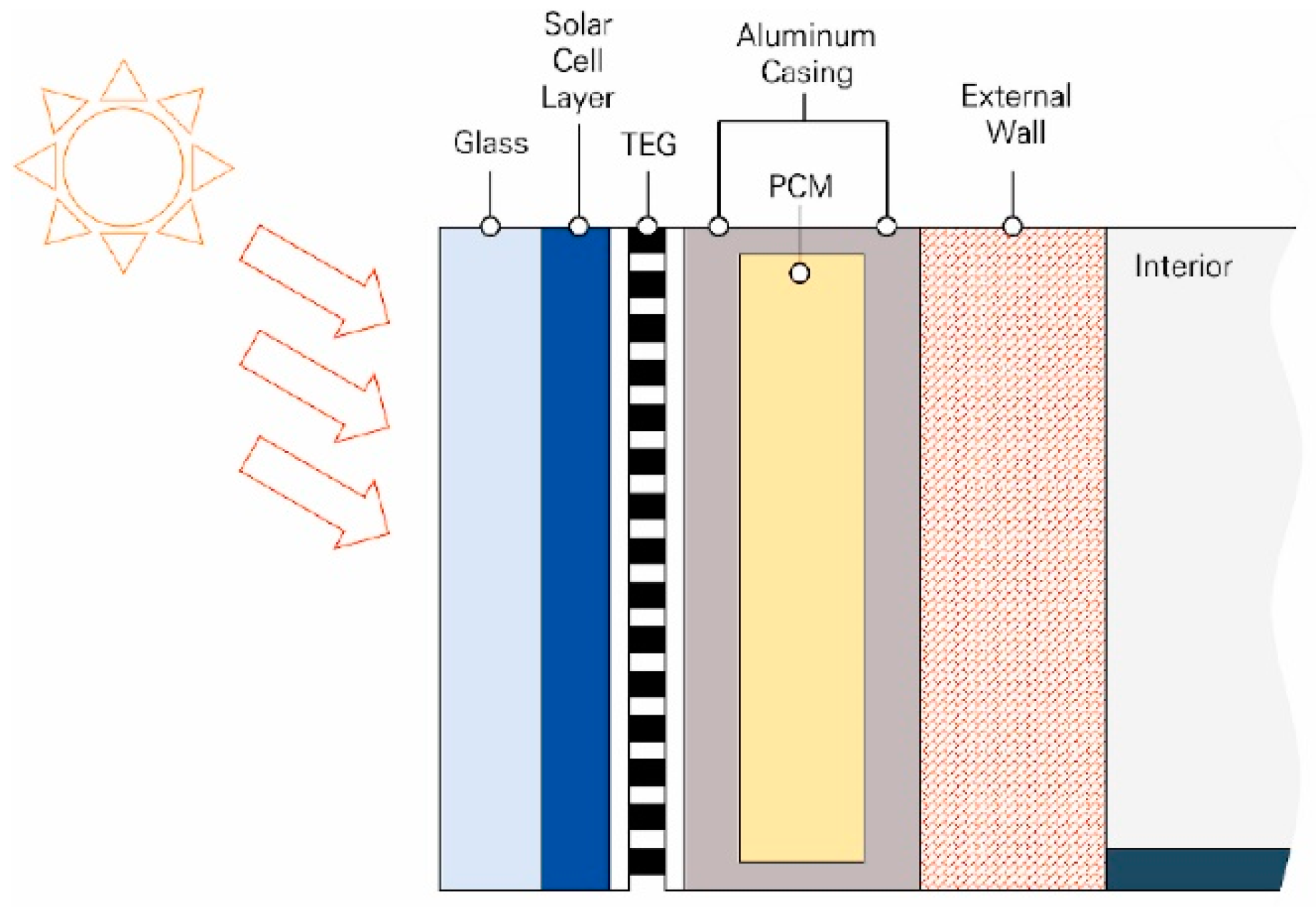
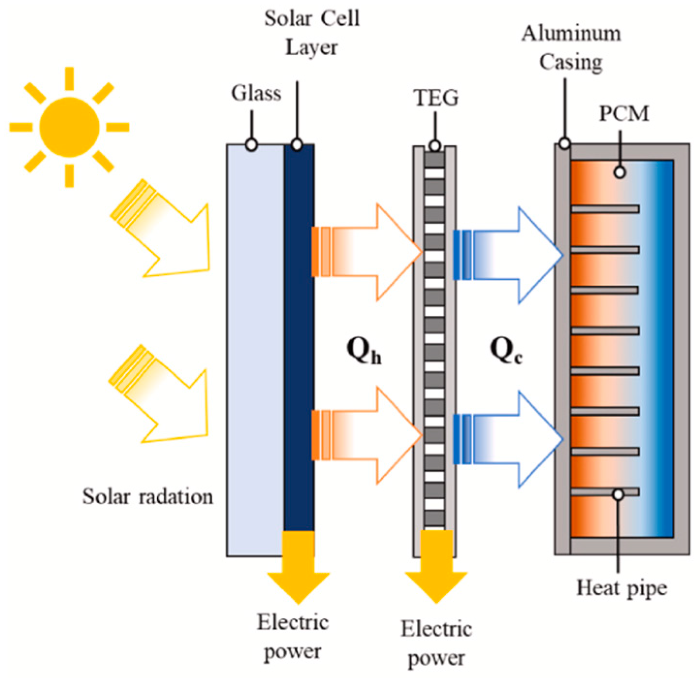
| BIPV-TEG-PCM System | Integrated with BIPV System and PCM | TEGs with PCM (35 °C melting temperature, 30 mm thickness) to reduce solar cell temperatures and harvest additional electricity | 1.09% increase in annual energy generation; seasonal improvements 0.91% to 3.16% (highest in winter) | Potential 4.47% energy increase by minimizing thermal resistance | [41] |
| Heat Pipe-Assisted BIPV-TEG-PCM System | Integrated with BIPV, PCM, and Heat Pipe | Enhanced BIPV-TEG-PCM with microencapsulated PCM (mPCM) and heat pipes | Efficiency improvements of 2% in intermediate seasons, 2.5% in summer | Improved long-term stability and heat transfer; addresses leakage issues | [42] |
| Climate-Specific BIPV-TEG-PCM System | Integrated with BIPV and PCM | Optimized for 5 climate regions; TEG spacing ≥205 mm, heat-fin spacing ≥200 mm | Performance varies by climate; PCM less beneficial in colder, drier climates | Recommended mPCM temps 20–40 °C for hot, humid climates; highlights climate-specific design needs | [43] |
| Solar Thermoelectric Wall with PCM (STEW-PCM) | Integrated into Building Wall with PCM | TEG with concrete wall and PCM for energy generation and climate control in subtropical regions | Up to 24.62 V/m2 (daytime); 16.31 V/m2 (nighttime) | Low energy conversion (<25% of solar radiation), high LCOE (35.37 c$/kJ) | [44] |
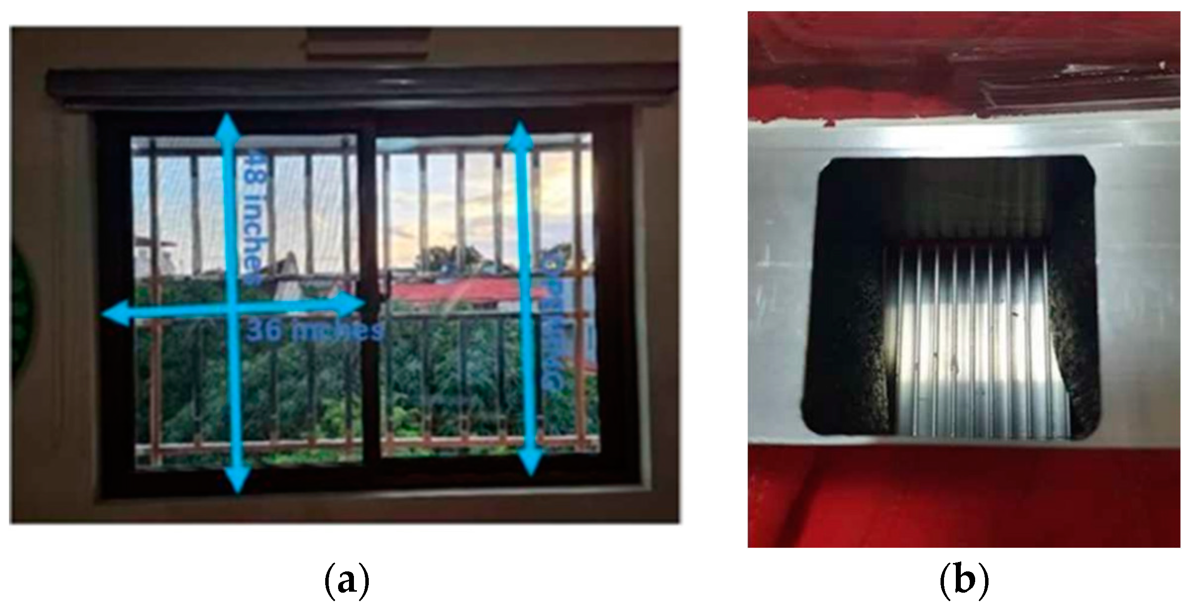
| TEG on Window Frame | On window frame surface | 12 TEGs on window frame with harvesting circuit, DC-DC boost converter, power bank; cooled by AC on one side | 0.61 W at peak (2 p.m.) | Highest voltage at peak temperature difference; exposed to environmental factors affecting durability and apparance | [45] |
| TEG Inside Window Frame | Fully contained within window frame | Thermally optimized connector, three-bridge internal structure | 1.5 mW under 6 °C temperature difference | Novel design balances heat transfer efficiency with minimal weight; self-powered for smart building sensors | [46] |
| TEG with Glazed Glass Insulation | Integrated into rooftop with glazed glass insulation | Uses temperature differential between sun-exposed surface and AC interior | Estimated 40 kWh/m² for summer months | Potential in high solar regions; concerns about net energy benefit due to AC reliance | [47] |
| TEG with Al-Si Alloy Roof Tiles | Integrated into Al-Si alloy roof tiles | TEGs with Al-Si alloy tiles (10 mm total thickness), 3 × 3 arrangement of heat sink bosses | 1.64 W with 10 tiles | Al-Si tiles superior in heat storage/transfer; energy loss in real-world applications needs refinement | [48] |
| Thermoelectric Energy Harvesting for BEM | In BEM wireless sensor networks | TEG, charge pump, switching regulator, DC/DC converter for high-temperature surfaces (60–80 °C) | 0.25 V to 0.45 V; 25% end-to-end conversion efficiency | Achieved 1.7% duty cycle, surpassing BEM requirements; low-temperature performance remains uncertain | [49] |
| TEG in Extreme Hot Climates | For building applications in extreme hot climates | Experimental measurements with numerical modeling for low temp differences (10 °C) | 22 mW at 10 °C difference; peak electrical efficiency 5.2% | Notable for low temp gradient energy harvesting; challenges in scaling to real-world applications | [50] |
| PCM-Integrated TEG Block | In building walls with PCM | TEG with PCM for passive cooling, using waste heat from walls | 2.1 kWh/m2 annually; average power 0.03 W, average voltage 0.3 V | Continuous, low-maintenance power for digital circuits; PCM crucial for heat management and energy harvesting | [51] |
| Energy Harvesting Block with TEGs and PCM | In energy harvesting blocks with TEGs and PCM | TEG-integrated heat sink with PCM layers (26 °C, 38 °C, 47 °C melting temps) | 46.5% increase in annual energy with 26 °C PCM compared to 38 °C PCM | Significant efficiency gains with optimized PCM selection for specific climates | [52] |
| LCPV/T-TEG Hybrid System | In low-concentration PV/thermal (LCPV/T) system | Compound parabolic concentrator, double-glazing PV panel, microchannel heat pipe array | Daily average overall efficiency: 57.03% (thermal 45.0%, PV 11.8%, TEG 0.23%) | High overall efficiency: TEG contribution modest compared to PV and thermal components | [53] |
| LCPV/T-TEG System Optimization | In LCPV/T system with focus on domestic hot water production | 40 series-connected TEGs directly on LCPV/T collector | Daily average output 436.13 W; TEG contribution 1.68 W (0.385% of total) | Optimized for higher PV output; TEG plays supplementary role | [54] |
| High-Performance STEG System | With solar absorbers and heat pipe evacuated tubular collector | Optimized TE materials, solar selective absorbers, heat management | Electrical efficiency 7.17% at 1032 W/m2; 5.2% at 1021 W/m2 | Significant electrical efficiency enhancement; concerns about long-term stability and economics | [55] |
| RSC-TEG System | With radiative cooling and TEG | Modified TiO2/PMMA radiative cooling film, commercial TEG, aluminum heat sink | Open circuit voltage 87 mV (2.3–3.2 °C difference); max ΔT 3.19 °C, UTEG 115.82 mV in optimal conditions | Better performance in autumn; challenges in small temperature gradient energy harvesting | [56] |
| Thermoelectric Ventilation System | With Concentrated Photovoltaic (CPV) System | CPV-TEG behind panels, max concentration ratio 5; converts solar energy for HVAC | Power output 58.85–154.29 W depending on the concentration ratio 1.0–5.0 | 14% power increase by strategic TEG positioning; 1.67% energy efficiency, 0.24% exergy efficiency in winter heating; outperforms summer cooling | [57] |
Disclaimer/Publisher’s Note: The statements, opinions and data contained in all publications are solely those of the individual author(s) and contributor(s) and not of MDPI and/or the editor(s). MDPI and/or the editor(s) disclaim responsibility for any injury to people or property resulting from any ideas, methods, instructions or products referred to in the content. |
© 2024 by the authors. Licensee MDPI, Basel, Switzerland. This article is an open access article distributed under the terms and conditions of the Creative Commons Attribution (CC BY) license (https://creativecommons.org/licenses/by/4.0/).
Share and Cite
Win, S.L.Y.; Chiang, Y.-C.; Huang, T.-L.; Lai, C.-M. Thermoelectric Generator Applications in Buildings: A Review. Sustainability 2024, 16, 7585. https://doi.org/10.3390/su16177585
Win SLY, Chiang Y-C, Huang T-L, Lai C-M. Thermoelectric Generator Applications in Buildings: A Review. Sustainability. 2024; 16(17):7585. https://doi.org/10.3390/su16177585
Chicago/Turabian StyleWin, Sein Lae Yi, Yi-Chang Chiang, Tzu-Ling Huang, and Chi-Ming Lai. 2024. "Thermoelectric Generator Applications in Buildings: A Review" Sustainability 16, no. 17: 7585. https://doi.org/10.3390/su16177585
APA StyleWin, S. L. Y., Chiang, Y.-C., Huang, T.-L., & Lai, C.-M. (2024). Thermoelectric Generator Applications in Buildings: A Review. Sustainability, 16(17), 7585. https://doi.org/10.3390/su16177585