Article

Hybrid Metaheuristic Secondary Distributed Control Technique for DC Microgrids

by
Olanrewaju Lasabi
1,*,
Andrew Swanson
1,
Leigh Jarvis
1,
Mohamed Khan
1 and
Anuoluwapo Aluko
2
1
Discipline of Electrical, Electronic and Computer Engineering, University of KwaZulu-Natal, Durban 4041, South Africa
2
Enerzinx, LLC., Ottawa, ON K1P 5J2, Canada
*
Author to whom correspondence should be addressed.
Sustainability 2024, 16(17), 7750; https://doi.org/10.3390/su16177750
Submission received: 6 August 2024 / Revised: 1 September 2024 / Accepted: 3 September 2024 / Published: 6 September 2024

Abstract

:
Islanded DC microgrids are poised to become a crucial component in the advancement of smart energy systems. They achieve this by effectively and seamlessly integrating multiple renewable energy resources to meet specific load requirements through droop control, which ensures fair distribution of load current across the distributed energy resources (DERs). Employing droop control usually results in a DC bus voltage drop. This article introduces a secondary distributed control approach aimed at concurrently achieving current distribution among the DERs and regulating the voltage of the DC bus. The proposed secondary control approach eradicates voltage fluctuations and guarantees equitable current allocation by integrating voltage and current errors within the designed control loop. A novel hybrid particle swarm optimization–grey wolf optimization (HPSO-GWO) has been proposed, which assists in selecting the parameters of the distributed control technique, enabling the achievement of the proposed control objectives. Eigenvalue observation analysis has been utilized through the DC microgrid state-space model designed to assess the influence of the optimized distributed secondary control on the microgrid stability. A real-time testing system was constructed within MATLAB/Simulink® and deployed on Speedgoat™ real-time equipment to validate the operations of the proposed technique for practical applications. The results indicated that the proposed secondary control effectively enhances voltage recovery and ensures proper current distribution following various disturbances, thereby maintaining a continuous power supply. The outcomes also demonstrated the capabilities of the control approach in accomplishing the control objectives within the DC microgrid, characterized by minimal oscillations, overshoots/undershoots, and rapid time responses.

1. Introduction

Electricity is considered the lifeblood of the modern digital world. However, in the foreseeable future, the potential scarcity of electricity is anticipated to become a significant concern for numerous nations, particularly in remote regions [1]. The main factors contributing to the absence of electricity access in these regions are either the considerable distance from the centralized power grid or the prohibitive expenses associated with power line installations over such distances [2]. Furthermore, rural areas typically exhibit significantly lower load demands than more densely populated regions. Hence, opting for grid electricity is less than optimal, due to the costs associated with transmission and routine maintenance. Moreover, the onset of global warming, dependence on biomass fuel, ozone layer depletion, CO 2 emissions, grid shutdowns, and the occurrences of power outages have collectively heightened awareness about the necessity for secure, sustainable, eco-friendly, and clean energy sources. The inherent intermittency of wind turbine generation (WTG) and photovoltaic (PV), which are the primary renewable energy sources (RESs) considered, poses significant challenges to their seamless integration into the utility grid [3]. In this context, opting for an isolated microgrids (MGs) system can be an ideal solution for remote areas lacking grid access, as it facilitates the consolidation of these resources in one central location [4]. In the existing literature, a diverse range of microgrid types has been utilized. These include hybrid AC/DC, AC, and DC microgrids that are employed to effectively manage both energy storage systems (ESSs) and RESs to meet specific energy demands [5]. The growth of DC microgrids (DC-MGs) is now outpacing that of traditional AC microgrids [6]. Problems with frequency, harmonics, and reactive power regulation are absent. Synchronization is also unnecessary in islanded mode [7,8]. To fully harness the capability of the DC microgrid (DC-MG) configuration, certain factors must be considered. These include ensuring compatibility with AC loads, as well as achieving a smooth shift between on-grid and stand-alone operations [9]. Protecting DC-MGs presents a challenge because of the lack of zero-crossing current and grounding constraints [10]. During fault conditions, Maintaining DC-MG stability becomes a substantial challenge. Mainly, this stems from the resistive impedance nature of DC-MG setups and the absence of physical inertia [9,11].
Despite the aforementioned challenges, the future of DC microgrids appears promising, mainly due to their enhanced compatibility with distributed energy resources (DERs), heightened reliability, and improved efficiency [4]. It is crucial to note that power converters are frequently utilized as interfaces in microgrids, facilitating each DER connection to the common bus [1]. Advancements in power electronics technology have enabled the cost-effective and seamless realization of DC microgrid schemes while achieving the necessary criteria [12]. With the introduction of direct current MG technology, DC loads found extensive utilization across various sectors, encompassing domains such as data centres and telecommunications facilities [13]. The functioning of many contemporary electronic devices, such as LED bulbs, televisions, and laptop/phone chargers, necessitates specific levels of DC voltage. Therefore, because of these features, DC microgrids have the potential to meet the growing needs of small and remote communities worldwide [14]. It is crucial to emphasize that the regulation of the bus voltage, along with effective current allocation within DC microgrids, are vital aspects that researchers must consistently prioritize [6]. The primary issues in a multi-source DC microgrid revolve around ensuring voltage stability and optimizing power allocation. In DC microgrids, the conventional droop method of control has been employed in the literature due to its simple implementation, which does not necessitate a communication network [15]. Nevertheless, this control approach faces challenges such as voltage fluctuations, regulating circulating currents, and achieving balanced current distribution, primarily due to droop and line resistance among the converters operating within the microgrid [4]. Effective management of these converters is necessary to attain the desired performance of a MG. It is important to highlight that the stability of voltage and the precision of current allocation are closely tied to the droop resistance. Precisely, as the droop resistance is heightened, there is an escalation in voltage deviations accompanied by an enhancement in current-sharing accuracy, and conversely [16]. This underscores the fact that choosing the value of the droop resistance involves an inherent trade-off within the controller. Hence, the traditional droop technique exhibits multiple limitations, including an intrinsic trade-off between load-sharing and voltage control, slow transient response, misalignment of line impedance among parallel converters affecting active power distribution, and suboptimal performance with DERs. Consequently, a secondary control loop, acting as an extra control layer for DC microgrids, can be integrated alongside the droop control [7,11]. Secondary control can be categorized into three main types: decentralized control, centralized control, and distributed control. A single central control system that establishes communication with all DERs within the microgrid is essential when utilizing centralized control. The central control must be capable of processing all data transmitted by components within the MG [16]. This control approach imposes significant reliance on the central controller, offers limited control reliability, and a substantial communication burden. The entire system could become immobilized in the event of a central controller failure or communication breakdown [16,17]. Eliminating the need for communication among the DERs, these constraints associated with centralized control are resolved by the decentralized control technique. Solely local measurements are used in implementing the control loop of each DER in operation within the MG. Implementation of a secondary decentralized control may be challenging, as it presents the liability of reducing the entire operational efficiency of the direct current MG. This can be attributed to the lack of a communication link, which restricts access to global information. Consequently, the output of the control may not sufficiently offset the droop-induced deviations [9,16].
The distributed control approach incorporates features of both centralized and decentralized control techniques, harnessing the advantages of each approach. Each DER in the microgrid is equipped with its individual secondary distributed control system, enabling communication via digital platforms such as low-bandwidth networks or power lines. These channels facilitate data exchange on parameters like bus voltage and DER output current among them [11,18]. This ensures the MG maintains full functionality, even if a communication link fails or a controller malfunctions, provided the network interconnection is maintained. Consequently, distributed control facilitates convenient plug-and-play operation of energy sources (ESs) and is resilient to mitigate the risk of a solitary point of failure. This makes it an appealing characteristic for microgrids [7,11]. Recent improvements in the distributed control approach have facilitated the implementation of a secondary control loop. This loop achieves control objectives such as voltage recovery and current allocation through a consensus-based approach, enhancing scalability, robustness, and reliability. In ref. [19], a distributed iterative algorithm employing a game theory framework is developed. The approach, designed for a DC microgrid, focuses on equitable current allocation and voltage recovery. A drawback of this method is the substantial computational workload it requires, relying on a comprehensive dataset to effectively understand the operations of the microgrid for peak efficiency. In ref. [20], a fixed-time distributed secondary controller based on emulated voltage drop is presented. While the control system successfully achieved the objectives of balanced current allocation and voltage restoration within a specified settling time, it overlooked the impact of line impedance in its design. A secondary distributed control based on average virtual current derivatives was implemented for DC-MGs in ref. [21]. This average derivative of the virtual current streamlines system analysis and enhances the development of more effective control strategies. While the approach considered the effects of constant power loads and line impedances, it did not thoroughly address the impact of communication time delays. In ref. [22], heterogeneous time delays were analysed to achieve optimal power allocation and accurate voltage regulation in DC-MGs utilizing consensus-based distributed control techniques. Although power distribution and voltage restoration are achieved, the design process for the secondary control becomes more complex due to the decoupling of power and voltage loops, and the impact of constant power load coupled with communication time delays was not thoroughly addressed. A distributed secondary controller which leverages event-triggered communication to lower operational costs is proposed in ref. [23] for DC microgrids. It disrupts the traditional hierarchy of tertiary optimization and secondary control by addressing power regulation and voltage recovery issues concurrently within the secondary layer. This approach does not address the limitation of line capacity and the application of its optimization algorithm encounters challenges, including delays in communication. In ref. [24], a distributed secondary controller utilizing a consensus protocol is proposed to tackle challenges related to current allocation and voltage recovery in a DC-MG. This technique employs a pair of PI controls: one tasked with maintaining a balanced distribution of current, and the other dedicated to voltage recovery. The corrective signals produced by these secondary controllers are relayed to their corresponding local primary controllers. Although implementing this technique is straightforward, it lacks the precision in correction terms required, potentially leading to reduced control performance as a result of this discrepancy. Ref. [25] presents an enhanced consensus-based distributed secondary control technique designed to ensure proper current allocation among DERs and regulate the bus voltages to their designated rated levels within a stand-alone DC-MG. Although the technique achieved the control objectives with just one connected DER, it did not account for line impedances or constant power loads. Additionally, A sparsity-promoting consensus-based secondary distributed control framework was proposed in ref. [26] for DC-MGs with multiple DERs. This approach minimizes the reliance on extensive information exchange across the communication network, making it more efficient and scalable. However, it does not account for the impact of communication time delays or constant power loads. The study in ref. [27] also introduces a supervisory distributed control that facilitates seamless transitions between two distinct secondary control mechanisms. These controls are specifically designed for current allocation and voltage restoration in the MG. The intricacy involved in adjusting multiple control coefficients and transients from the frequent operation of the switching circuit are the constraints related to this approach. In ref. [17], a cooperative distributed control method for current allocation and voltage recovery in a DC-MG is formulated. The method employs discrete consensus with limited communication between neighbouring DERs, taking into account control system implementation, data exchange and the discrete nature of measurements. The conflict between current distribution and voltage restoration in a DC-MG was explored in ref. [28]. The authors employed a distributed learning-based high-order fully actuated secondary control for DC-MGs. This approach effectively achieved precise current allocation, regulated bus voltage, and demonstrated strong adaptability to perturbations within the studied scenario. However, the influence of communication time delays, along with system uncertainties and parameter variations, was not thoroughly addressed. In ref. [29], an integral-type distributed secondary control method is introduced, employing event-triggered communication. This approach aims to ensure a balanced allocation of current and reliable voltage restoration within a stand-alone DC MG. This technique achieves its control objectives with negligible dependence on sporadic communication, leading to significant reductions in communication expenses. Nonetheless, the effectiveness of this approach diminishes once the converters lack access to the bus voltage. Moreover, this method exclusively addresses resistive loads, limiting its ability to accommodate other types of loads.
Table 1 provides a comprehensive analysis of the proposed technique, offering a detailed comparison with the methods discussed earlier. This comparison highlights the distinct features, advantages, and limitations of each approach, thereby illustrating the strengths of the proposed technique relative to existing alternatives. Based on the review of current research, it is evident that developing the secondary control system necessitates the incorporation of two control loops for current allocation and voltage recovery. Incorporating the control signal from the secondary control system into the primary control loop often involves balancing between current allocation and voltage recovery. Hence, this paper aims to develop a control scheme that achieves a harmonious balance between voltage recovery and current allocation, addressing both objectives simultaneously. This article proposes a distributed control approach that integrates voltage control and current distribution loops linearly within the secondary control loop for an islanded direct current microgrid (DC-MG). The distributive characteristics guarantee resilience in the operation of the microgrid. Every energy source within the DC-MG is provided with its secondary control system to establish the distributive features. Nevertheless, communication among the ESs is implemented to ensure consensus operations. The control trade-off is resolved through the introduction of a weighting coefficient designed to harmonize the control objectives of current allocation and voltage recovery. A meta-heuristic optimization (MHO) approach is utilized to determine this weighting coefficient. Recent research indicates a significant lack of focus on employing MHO techniques. These approaches are notable for their ability to effectively tackle intricate problems and optimize control coefficients [30]. This omission relates to tackling the major issues identified in previous research within the DC-MG secondary control loop. Tackling these challenges may involve applying various MHO algorithms. Examples of algorithms in this group are the ant lion algorithm, the grey wolf optimization (GWO) algorithm, the particle swarm optimization (PSO) method, and the gravitational search algorithm. Considering their intrinsic advantages and constraints, it is essential to highlight that no single optimization algorithm can guarantee the optimal operational system performance. For example, take PSO, known for its simple concept, computational efficiency, and adaptability to control parameters. However, its limited global/local search capabilities can lead to it getting stuck in a local minimum when confronted with extremely constrained and robust scenarios [1]. Another instance is the GWO, which has shown better performance in comparison to all the aforementioned algorithms [31]. Despite the notable strengths of GWO, such as its straightforward implementation, rapid convergence, and superior effectiveness in complex and uncertain search environments, especially in engineering contexts [32], its significant drawbacks encompass delayed late-stage convergence and susceptibility to local optima [33]. Undoubtedly, both of these algorithms exhibit distinct search strategies. The strategies they employ for updates, which two or three agents influence, can result in reduced diversity, premature convergence, or convergence towards a local optimum [34]. To tackle these challenges, previous studies have suggested the integration of multiple algorithms through hybridization, aiming to achieve peak system performance. Implementing Hybrid PSO-GWO (HPSO-GWO) can leverage the unique strengths of both PSO and GWO. The primary goal of this hybrid approach is to incorporate the exploratory strength of GWO to enhance the exploitation capabilities of PSO [1]. Consequently, this paper aims to tackle the challenges related to current allocation and voltage recovery within DC-MGs by utilizing the HPSO-GWO algorithm to adaptively determine the weighing coefficient introduced in the secondary control loop. The optimization algorithm is distinguished by its simplicity and user-friendliness as an effective tool for problem-solving, along with its competitive performance when compared to others [35]. Employing this algorithm to uncover the optimal solution to the global-best optimization problem has demonstrated its effectiveness [36]. Such utilization can significantly improve the secondary control loop performance of DC-MGs. It is worth noting that the proposed technique offers substantial contributions, including minimized overshoot/undershoot, reduced settling time across various operating scenarios, enhanced current allocation among paralleled ESs operating within the DC-MG, and improved bus voltage recovery within the specified 5% tolerance. Stability analysis was carried out on the proposed control approach using Eigenvalue analysis. In addition, the proposed approach consumes less communication bandwidth, thus leading to reduced communication expenses. The proposed distributed secondary control and DC-MG are implemented in real-time using a Speedgoat™ real-time digital platform under various operating scenarios in order to evaluate the robustness of the control technique in achieving its control objectives for practical applications.
In summary, this study has contributed the following:
  • A secondary distributed control approach for a DC-MG, introducing a novel weighting coefficient that simultaneously eliminates bus voltage fluctuations and ensures equitable current allocation across multiple ESs.
  • A novel hybrid algorithm combining PSO and GWO is introduced to enhance coefficient selection for the distributed control strategy in the microgrid. This advanced algorithm optimizes the control coefficient, thereby ensuring that the control objectives are effectively achieved. By leveraging the strengths of both PSO and GWO, the proposed method provides a robust solution for fine-tuning the control coefficient, which enhances the overall performance and reliability of the DC-MG.
  • A state-space model of a DC-MG incorporating eigenvalue observation analysis is developed to assess the effects of the optimized secondary distributed control on the microgrid’s stability. This analysis provides valuable insights into the system’s stability dynamics, helping to understand how the control strategy influences overall system performance.
  • A real-time testing setup is constructed using MATLAB/Simulink® and implemented on a Speedgoat™ real-time target machine to validate the practical performance of the proposed approach in real-world applications.
The organization of the article is as outlined: Section 2 delves into the discussion of DC-MG state-space (S-S) models for DC-MG, encompassing the model for primary control loops. The novel secondary distributed control approach model is detailed in Section 3. Section 4 provides an overview and formulation of the HPSO-GWO tuning technique utilized for tackling the issue under discussion. The performance evaluation results of the proposed technique, including the stability analysis, are presented in Section 5. Finally, the accomplishments attained in this research are summarized in Section 6.

2. Mathematical Model DC Microgrid Systems

The section outlines the mathematical model derivation for small-signal analysis of the elements within the DC-MG. In this MG configuration, all MG loads are interconnected with the DC bus, and likewise, ESs are interconnected in parallel to a shared DC bus. The coordination and management of MG are accomplished through a hierarchy architectural control system consisting of tertiary, secondary, and primary controls. Nevertheless, the focus of our research is restricted to the primary and secondary control tiers. The S-S model is formulated for an individual energy source converter, along with the corresponding mechanisms of control. The model can be extended to encompass multiple DERs in a DC-MG configuration [37].

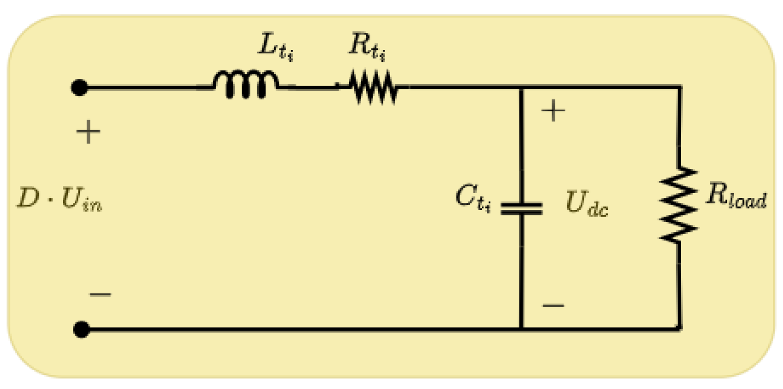
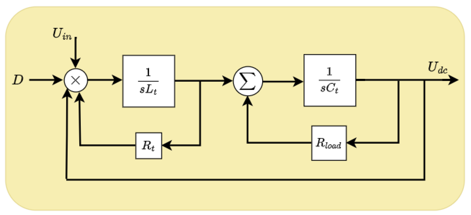
2.1. Model of Buck Converter

The converter generates a reduced output DC voltage ( U d c ) when compared to its input voltage ( U i n ). In order to formulate the converter S-S model, the equivalent circuit depicted in Figure 1 suffices for capturing the converter’s average performance while disregarding its high-frequency characteristics. The converter dynamic behaviour can be expressed as [26]
d U d c ( t ) d t = 1 C t ( I L t U d c R l o a d ) ,
d I L t ( t ) d t = 1 L t ( D · U i n I L t · R L t U d c ) ,
where D, C t , L t , I L t , R L t , and R l o a d depict the converter duty cycle, converter capacitance, converter inductance, inductor filter current, parasitic inductance resistance, and load resistance, respectively. The Laplace transform of (1) and (2) are obtained and reorganized to form the transfer function, as described in (3), to assess the converter’s stable operational performance, whose block diagram is illustrated in Figure 2.
U d c ( s ) D · U i n ( s ) = 1 L t C t · s 2 + ( R L t C t + L t R l o a d ) s + ( 1 + R L t R l o a d )
The minimum capacitance ( C t ) and inductance ( L t ) values can be ascertained through
C t = Δ i L t 8 Δ v o f s w , L t = D ( U i n U d c ) 2 Δ i L t f s w ,
where f s w depicts the converter’s switching frequency. Δ v o and Δ i L t represent the peak DC voltage output and inductor current ripples, respectively.

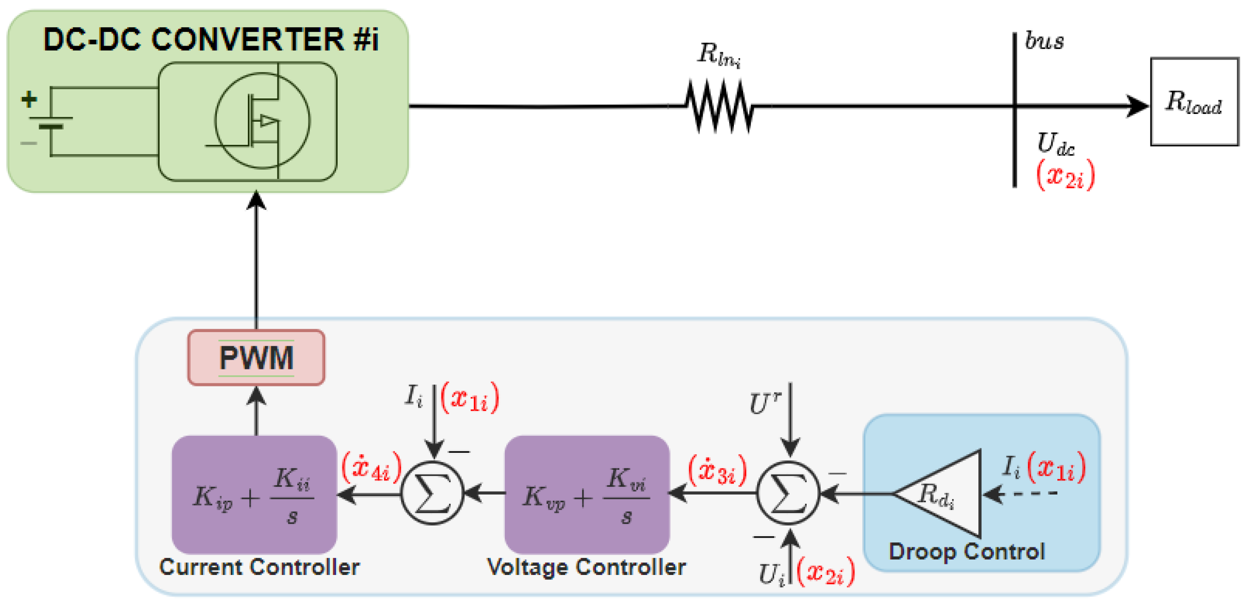
2.2. Buck Converter Primary Controls

The converter primary controls mainly utilize a duo PI-type controller, each for current and voltage control, coupled with the drop control, which utilizes a P-type control. This is illustrated in Figure 3. To control the DC output voltage, the reference signal used by the current control is generated by the voltage control, which then produces the duty cycle as a reference for the converter’s PWM to control the output current. Compared to the voltage controller, the current controller is designed to respond more quickly to avoid instability.
In situations where several direct current converters are interconnected in parallel to the common direct current bus, droop controls serve as the first control tier implemented to coordinate these converters. Ensuring a predefined current distribution ratio within the MG is the primary goal of droop control. Considering the DC-MG set-up illustrated in Figure 4, the bus voltage is defined as
U d c = U i r I i R l n i ,
where R l n i is the line resistance, U i r is the voltage reference, and I i is the output current of the ith energy source converter. The voltage reference, set by a droop control to facilitate current allocation, is
U i r = U r I i R d i ,
where U r represents the rated DC voltage and R d i depicts the droop resistance of the ith energy source converter. Analysing (5) and (6) for the D E R i and D E R j converters, which are connected to the common DC bus, the droop correlation is deduced as
( R l n i + R d i ) I i = ( R l n j + R d j ) I j ,
and
I i I j = R l n j + R d j R l n i + R d i R d j R d i ,
assuming R d > R l n .
Based on the layouts presented in Figure 3 (state variables in red), the stability analysis for the converter primary controller is undertaken by formulating the S-S model. x 4 i and x 3 i denote the output current and voltage control integrator, respectively. x 2 i and x 1 i are capacitor voltage output and inductive current for the ith energy source converter, respectively. Based on the droop controller operations, the dynamical description of the voltage control integrator input reference for the ith energy source converter is expressed as
x ˙ 3 i = U r R d i x 1 i x 2 i .
In the same vein, the dynamical description of the current control integrator input reference produced by the voltage controller is formulated as
x ˙ 4 i = K v i i x 3 i + K v p i x ˙ 3 i x 1 i = K v i i x 3 i + K v p i ( U r R d i x 1 i x 2 i ) x 1 i = ( 1 K v p i R d i ) x 1 i K v p i x 2 i + K v i i x 3 i + K v p i U r ,
where K v p i represents the proportional coefficient and K v i i is the integral coefficient of the voltage controller for the ith energy source converter. To complete the state-space modelling of the converter actively functioning within the DC-MG, the DC output current and voltage can be deduced from (1) and (2) as
x ˙ 1 i = 1 L t i ( ( K i p i K i p i K v p i R d i ) x 1 i K i p i K v p i x 2 i + K v i i K i p i x 3 i + K i i i x 4 i + K i p i K v p i U r ) ,
x ˙ 2 i = 1 C t i x 1 i 1 R l o a d C t i x 2 i ,
where K i p i represents the proportional coefficient and K i i i is the integral coefficient of the current controller for the ith energy source converter. Integrating the primary controller within the framework of a DC-MG system and using (9) to (12), the S-S modelling of the ith energy source converter can be described in a conventional state-space structure as
X ˙ m i = A m i X m i + B m i U Y m i = C m i X m i ,
where B m i depicts the input matrix, and C m i is the output matrix, described by (14). The state matrix, stated by (15), is denoted by A m i and state vector, X m i = [ x 2 i , x 1 i , x 3 i , x 4 i ] T . U = [ U r ] and Y m i are the input and output vector, respectively.
B m i = 0 K i p i K v p i L t i 1 K v p i T , C m i = 1 0 0 0 0 1 0 0
A m i = 1 R l o a d C t i 1 C t i 0 0 K i p i K v p i L t i ( K i p i K i p i K v p i R d i ) L t i K v i i K i p i L t i K i i i L t i 1 R d i 0 0 K v p i ( 1 K v p i R d i ) K v i i 0 .
Upon examination of (5), it becomes evident that a bus voltage ( U d c ) variation steadily occurs when the current exceeds a zero value. Additionally, it is apparent, from (6), that when the droop resistance R d is increased substantially to enhance precise current distribution, it results in a DC voltage deviation. Hence, the primary control alone is incapable of attaining uniform current allocation within the DC-MG without producing a notable bus voltage variation. To attain both balanced current allocation and voltage regulation concurrently, a secondary controller is implemented.

3. Secondary Distributed Controls

An innovative distributed secondary control method is devised in this study, to enable voltage recovery and equitable current allocation concurrently in an autonomous DC-MG, with numerous ESs linked in parallel to a shared bus. Each energy source converter in the MG is furnished with its own independent primary controls, which operate autonomously in a decentralized manner. The droop control-induced variation is compensated for by the newly generated secondary control reference signal. To mitigate the inherent single-point failure issue linked with centralized controls, the distributed secondary control approach integrates a communication link among the DERs. In this approach, each energy source, provided with its own secondary controller, can exchange information with other secondary controls within the DC-MG via the communication link.

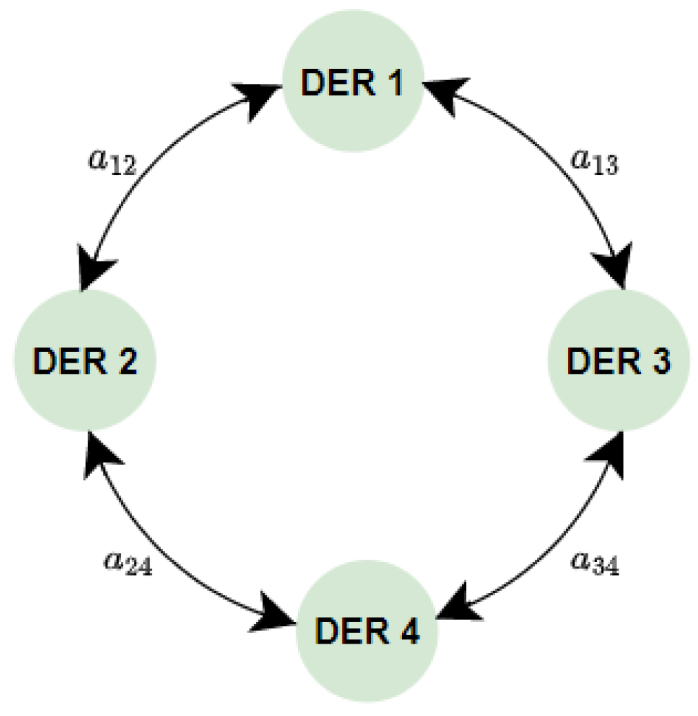
3.1. Communication Graph

Through a reduced communication network, the ESs are synchronized in a distributed fashion in this research, as shown in Figure 5. The aggregate count of DER examined is depicted as n. The communication network under examination is modelled as a connected and undirected graph, G = ( V n , E ) , with V n = { v 1 , v 2 , , v n } representing the set of nodes, and E V n × V n depicting a collection of viable communication links among the nodes. A node V j is considered as a near-neighbouring node of V i if information can be shared between the two nodes or, equivalently, ( v i , v j ) E n . N i represents the set of neighbouring nodes for node i. In addition, A = { a i j } describes the adjacent matrix of the communication graph, with ( v i , v j ) E n , a j i = a i j = 1 and ( v i , v j ) E n , a j i = a i j = 0 . D = d i a g { d i j } also represents the degree matrix of the graph, where d i j = j N i a i j and the Laplacian matrix, L , can be formulated as L = D A . Suppose there is an information exchange between nodes j and i, consensus on the variable q is considered achieved if q i ( t ) q j ( t ) 0 . Following the first-order consensus equation [38], this consensus can be formulated as
q ˙ i = j = 1 n a i j ( q i q j ) i = 1 , 2 , , n ,

3.2. Control Objectives

Restoring the bus voltage to its designated value is one of the objectives of the proposed secondary control approaches illustrated in Figure 6. This bus voltage variation, influenced by the droop’s action, is computed from (5) and (6) to derive
Δ U d c = U r U d c = ( R l n i + R d i ) I i .
Thus, the first objective of restoring the bus voltage is articulated as
lim t Δ U d c ( t ) = 0 o r lim t U d c = U r .
Another objective of the proposed secondary control approach is to ensure equally distributed current. This will eventually lead to equal allocation of power among the ESs connected in a parallel fashion. The mathematical description for current allocation in (8) leads to deviations in the bus voltage; therefore, for the ith DER, current allocation objective can be derived as
lim t Δ I i ( t ) = 0 ,
where
Δ I i ( t ) = j N , j i a i j I i ( t ) c i 1 N 1 I j ( t ) c j ,
where c i and N depict the current allocation ratio of the ith energy source and the count of ESs within the DC-MG, respectively. The entries of the adjacency matrix, a i j , are set to one to indicate connection and to zero to signify the absence of a communication link between neighbouring ESs.

3.3. Proposed Design for Secondary Control

In pursuit of the established objectives, the distributed secondary control, as illustrated in Figure 6, is designed to compensate for the droop-induced voltage variations. Thus, the expression for the bus voltage recovered by the proposed distributed control implemented into the DC-MG is described by employing (5) as
U d c = U r R l n i + R d i I i + Q i ( t ) ,
where, for the ith energy source, Q i represents the secondary control generated input signal into the primary control loop. This signal is derived using the feedback control law as
Q i ( t ) = ρ i · e i t ( t ) ,
where e i t denote the integral combination of the errors or deviations, described as
e i t ( t ) = α i Δ U d c ( t ) d t + β i Δ I i ( t ) d t ,
with α , ρ , and β denoting the proposed secondary control coefficients.
To assess the influence of the newly introduced secondary control on the stability of the DC-MG, we formulate the control system dynamical expressions. The reference voltage error input, expressed in (9), is modified by incorporating the secondary control to yield
x ˙ 3 i = U r R d i x 1 i x 2 i + Q i .
Thus, for the newly introduced distributed secondary control, the dynamical expression can be derived as
Q ˙ i = ρ β x 1 i β N 1 j N x 1 j α x 2 i + α U r .
Employing (10)–(12), alongside (24) and (25), the S-S model for the ith energy source, integrating the secondary control, can be formulated as
X ˙ s m i = A s m i X s m i + B s m i U Y s m i = C s m i X s m i ,
where B s m i depicts the input matrix, and C s m i is the output matrix, described by (27). The state matrix, stated by (28), is denoted by A s m i and state vector, X s m i = [ x 2 i , x 1 i , x 3 i , x 4 i , Q i ] T . U = [ U r ] and Y s m i are the input and output vector, respectively.
B s m i = 0 K i p i K v p i L t i 1 K v p i ρ α T , C s m i = 1 0 0 0 0 0 1 0 0 0
A s m i = 1 R l o a d C t i 1 C t i 0 0 0 K i p i K v p i L t i ( K i p i K i p i K v p i R d i ) L t i K v i i K i p i L t i K i i i L t i 0 1 R d i 0 0 1 K v p i ( 1 K v p i R d i ) K v i i 0 0 ρ α ρ β 0 0 0 .
Selecting the newly introduced distributed control coefficient values to achieve the objectives of current allocation and voltage recovery is a complex and time-consuming endeavour. This intricacy stems from the impact of these coefficients on the response of the converters and their implications for the DC-MG stability. Through elementary analysis, it becomes apparent that opting for a high value of α accelerates convergence towards attaining the control objective for bus voltage recovery, whereas choosing a high value of β expedites convergence towards attaining the control objective for current allocation. By convention, β is usually chosen to be of greater value than α . This decision is due to the fact that the current allocation objective requires attaining consensus across all ESs, whereas the voltage restoration objective concerns a universal target for the DC bus. Therefore, in order to improve adaptability, increase flexibility, and streamline the tuning process of the distributed secondary control, we introduce an innovative and enhanced tuning approach for choosing the appropriate value of ρ . This coefficient is critical, as it serves as a weighting factor that governs the balance between the objectives of voltage recovery and current allocation.

4. Enhanced Tuning Technique for Secondary Distributed Control

This section presents a novel tuning method for the proposed distributed control weighing coefficient, ρ . This tuning approach is the hybrid PSO-GWO (HPSO-GWO) optimization algorithm, which bolsters the exploitability of PSO by leveraging the exploration capabilities of GWO.

4.1. Particle Swarm Optimization (PSO)

Eberhart and Kennedy pioneered the development of the population-based MHO method known as PSO [36]. It draws inspiration from the social behaviour observed in fish schools or bird flocks as they forage for food. In this PSO technique, the initial population is initially created randomly within the search domain. This approach continuously maintains in memory the optimal location for each individual particle and the positional data of the top-performing particle within the swarm. In each iteration, every particle within the swarm adjusts its position according to the following equations:
v i n + 1 = w v i n + c 1 k 1 ( p i n y i n ) + c 2 k 2 ( p g y i n ) ,
y i n + 1 = y i n + v i n + 1 .
In this context, w represents the inertia weight parameter, i denotes a specific particle within the swarm, n signifies the current iteration step, and the values k 1 and k 2 are selected from the interval [0, 1] as random numbers. p g denotes the best position information within the entire swarm. p i signifies the best location achieved by the ith particle, v is the velocity, y represents the position, and the optimization parameters are denoted by the coefficients c 1 and c 2 .
In the PSO algorithm, there is a slight chance that the new velocity and position of a particle may not be accepted; in such cases, the particle’s position is substituted with a random one drawn from the exploratory region. This process is objective is to evade local minima. The search persists until an optimal result is attained or it reaches a predefined maximum number of iterations.

4.2. Grey Wolf Optimizer (GWO)

The GWO algorithm draws inspiration from the hierarchical leadership structure observed in grey wolf packs [39]. At the pinnacle of the food chain, grey wolves reside. Within the leadership hierarchy are four distinct categories of grey wolves: omega, delta, beta, and alpha. In this algorithm, alpha wolves embody the best solution achieved, while beta and delta wolves stand for the second- and third-best solutions within the population, respectively. Omega wolves are potential candidates for the best solution. It is assumed in GWO algorithm that the hunting is carried out by delta, beta, and alpha wolves, with omega wolves trailing behind and following their lead. The hunting behaviour of grey wolves encompasses three primary phases: firstly, tracking, pursuing, and closing in on the prey. Secondly, engaging in a chase, encircling, and harassing the prey until it ceases movement. Thirdly, launching an attack on the prey. Mathematical modelling of the process of prey encircling is expressed through the following:
b = | c · y p ( t ) y ( t ) | ,
y ( t + 1 ) = y p ( t ) d · b ,
where y , y p , and t represent grey wolves location, prey position, and number of instantaneous iterations, respectively. d and c are both vector coefficients, which can be computed as follows:
d = a · ( 2 k 1 1 ) ,
c = 2 k 2 .
In this context, the variable a gradually decreases in a linear fashion from 2 to 0 as the number of iterations diminishes. k 1 and k 2 denote random numbers selected uniformly from the range [0, 1].
Alpha wolves take the lead in guiding grey wolves to locate the prey, occasionally receiving assistance from beta and delta wolves. The GWO algorithm operates under the assumption that the alpha wolf represents the best solution, while the second- and third-best solutions are embodied by the beta and delta wolves, respectively. Consequently, the remaining wolves in the population adjust their movements based on the positions of these three wolves. This is mathematically formulated as follows:
b a l p h a = | c 1 · y a l p h a y | ,
b b e t a = | c 2 · y b e t a y | ,
b d e l t a = | c 3 · y d e l t a y | ,
where y a l p h a , y b e t a , and y d e l t a denote the placement of the best three wolves with respect to their corresponding prey locations within the exploratory region in each iteration, respectively.
y 1 = y a l p h a d 1 · b a l p h a ,
y 2 = y b e t a d 2 · b b e t a ,
y 3 = y d e l t a d 3 · b d e l t a ,
y p ( t + 1 ) = y 1 + y 2 + y 3 3 .
In this context, the updated prey position is represented as y p ( t + 1 ) , calculated as the average of the final positions of the three top-performing wolves within the population.
Grey wolves conclude their hunting process by launching an attack on the prey, necessitating their proximity to the target. Upon analysing (33), it becomes evident that the variable d spans values within the range of [ 2 a , 2 a ] , with a gradually decreasing from 2 to 0. If the | d | value equals or exceeds 1, ongoing hunts are forsaken in pursuit of superior solutions. Given that the prey has approached sufficiently close, with | d | less than 1, grey wolves are compelled to launch an attack on the prey. This method safeguards wolves from becoming trapped in local minima. Scouting for prey exemplifies the exploratory capability while engaging in an attack on the prey showcases the exploitative capability. The search process concludes once the GWO algorithm attains the specified number of iterations.

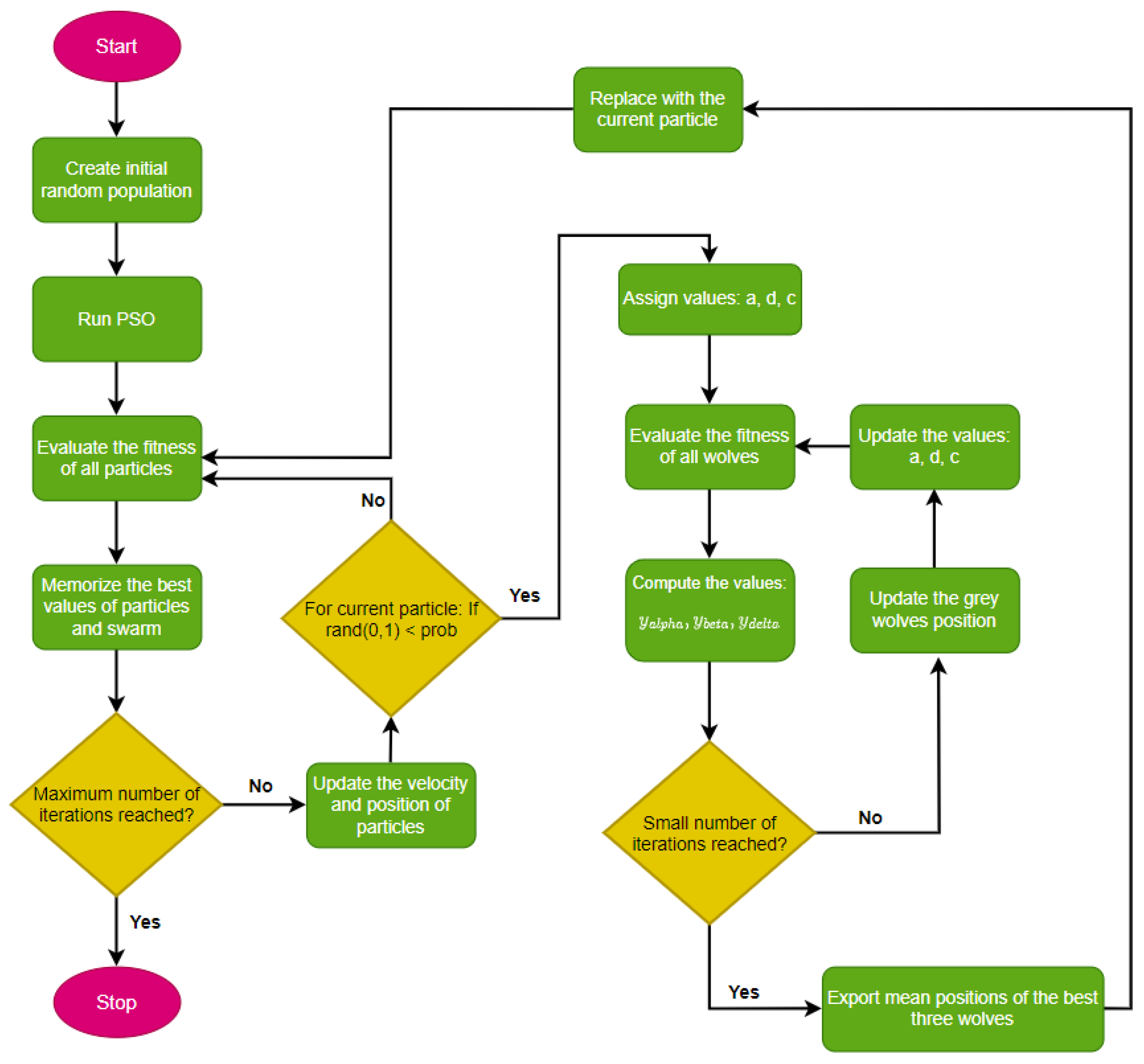
4.3. Hybrid PSO-GWO Algorithm

HPSO-GWO is an innovative swarm-based meta-heuristic offering several advantages, such as minimal memory consumption and straightforward implementation [36,40]. The core idea revolves around combining PSO’s exploitation prowess with GWO’s exploratory capabilities, thereby harnessing the strengths of both methods and managing memory usage efficiently. As a result, this approach operates in a co-evolutionary manner, with both variants running concurrently rather than sequentially. In hybrid PSO-GWO, rather than employing the usual mathematical expressions, we manage the exploitation and exploration of the GWO within the search space through the use of an inertia constant. Therefore, the position updates of the first three agents within the exploratory region are computed using the formulated mathematical expressions in (42)–(44).
b a l p h a = | c 1 · y a l p h a w y |
b b e t a = | c 2 · y b e t a w y |
b d e l t a = | c 3 · y d e l t a w y |
where w depicts the inertia weight parameter and is employed to control the balance between the exploitation and exploration of the grey wolf within the search space. All the previously mentioned details can be utilized to compute the precise distances between the current positions of the best grey wolves and their respective prey locations within the space, denoted as b a l p h a , b b e t a , and b d e l t a , as outlined in (42) through (44). These distances are utilized in (38) through (40) to compute final positions of these wolves ( y 1 , y 2 , and y 3 ). The computed parameters in (38) through (40) are then employed in (41) to ascertain the predicted prey position. The positions and velocities of the wolves denoted as y i n and v i n , can be updated using the PSO scheme according to the following expressions:
v i n + 1 = w ( v i n + k 1 c 1 ( y 1 y i n ) + k 2 c 2 ( y 2 y i n ) + k 3 c 3 ( y 3 y i n ) ) ,
y i n + 1 = y i n + v i n + 1 ,
where y i n + 1 and v i n + 1 denote the best three grey wolves’ updated position and velocity values, w signifies the inertia, generated continuously within the range [ 0 , 1 ] . Additionally, k 1 , k 2 , and k 3 are random values falling within the interval [ 0 , 1 ] . Furthermore, y 1 , y 2 , and y 3 represent the best three wolves’ positions, determined using (38)–(40). The optimization parameters, denoted as c 1 , c 2 , and c 3 , are set to a constant value of 0.5, and y i n represents the particle’s present position.

4.4. Implementation of Hybrid PSO-GWO for Distributed Secondary Control

To enhance the efficiency of the DC-MG, specifically in achieving current and voltage control objectives, this research introduces a control approach that optimizes the newly introduced parameter of the distributed secondary controller, denoted as ρ , based on the fitness function in (47). The integral time absolute error (ITAE) objective function is opted for in this article for its capability to achieve reduced overshoots, shorter settling times, and faster rise times compared to other typically used objective functions in the literature [41] while maintaining adherence to the constraints outlined in (48). Moreover, the control goals of the newly introduced control are attained by guaranteeing that the current allocation and voltage variation errors asymptotically converge to zero. For achieving optimal control tuning, the chosen fitness function is expressed as
D = 0 T t · ( Δ I i + Δ U d c ) d t
Incorporated within the HPSO-GWO Matlab code are the lower and upper boundaries of the secondary control coefficient, ρ , facilitating the identification of optimal values based on the system specifications, as illustrated:
ρ m i n ρ ρ m a x
where ρ m i n is the lower and ρ m a x is the upper limits of the weighting parameter introduced in the secondary controls for DC-MG, as depicted in Figure 6. By restricting this value, the HPSO-GWO algorithm can efficiently explore appropriate values for ρ within a predetermined range that aligns with the system specifications. HPSO-GWO algorithm pseudocode is outlined in Algorithm 1 as follows:
Algorithm 1 HPSO-GWO Algorithm Implementation
 Require:
Generate a random population
 Require:
Set a small probability rate, p r
 Require:
Set maximum iterations and initialize iteration count as I t r = 0
Run PSO to evaluate the fitness of all particles (47)
Sort and index the fitness values of each particle.
if  I t r = m a x I t r  then
    stop
else
    update velocity and position of particle using (45) and (46), respectively
end if
for current particle do
    if rand(0,1) < p r  then
        assign values to a, d, and c       ▹To avoid getting trapped in local minima
    else
        run PSO to evaluate the fitness of all particles
    end if
    Evaluate the fitness of all wolves
    Update wolves position y a l p h a , y b e t a and y d e l t a using (38)–(40)
    if  I t r < m a x I t r  then
        Compute new wolves position, y p ( t + 1 ) (41)
        Substitute this position to PSO particles
        Run PSO
    else
        update the wolf position
    end if
end for
Figure 7 illustrates the procedure for the secondary control parameter selection through the HPSO-GWO algorithm. In this context, multiple random populations are initialized with specified PSO and GWO parameters to set the initial value of the weighing coefficient, ρ , for the system. This initial parameter is then employed within the secondary control loop to assess the performance of the MG. If the microgrid’s performance is deemed unsatisfactory, indicating unregulated bus voltage and imprecise current distribution among its DER sources, the current and the voltage errors arising from the differences between the rated and the measured values are integrated into the fitness function expressed in (47), and are then utilized in the HPSO-GWO code to recompute the new value for ρ within the secondary control loop. The main goal is to reduce errors, potentially enhancing the operations of the distributed controls within the DC-MG. It is important to note that the iterative process persists until the microgrid achieves its optimal performance.

5. Results and Discussion

This section demonstrates the effectiveness of the newly introduced secondary controller through various simulation cases. Our test cases assume energy sources, such as energy storage, that have a constant DC voltage source within the time frame of interest. A DC-MG S-S model with three energy resources is formulated using MATLAB/Simulink® R2023b software. This model leverages the control strategies and the mathematical framework of a single converter, outlined in Section 2 and Section 3. Eigenvalue analysis was performed on the microgrid model, incorporating both primary and secondary controls, to evaluate stability. The efficacy of the control in attaining its control objectives in relation to voltage recovery and current allocation is evaluated using the developed S-S model of the DC-MG. Table 2 [42,43] outlines the parameters employed in the S-S model of the DC-MG.

5.1. Stability Analysis

System stability is assessed by examining the state matrix eigenvalues (A matrix). In the event that all the A matrix eigenvalues exhibit negative real components, the system is deemed stable, asymptotically. In practical terms, this signifies that the system will recover its state of equilibrium following a small-signal perturbation. This section presents a formulation of the state matrix, A m , for the DC-MG using only primary control through (15), and the state matrix A s m , incorporating the proposed secondary control through (28). Table 3 displays the eigenvalues of the DC-MG under the operation of both primary and secondary control systems. With primary control, the system’s eigenvalues include positive real parts ( λ 2 and λ 3 ), rendering the DC-MG unstable. However, with the incorporation of the secondary controller, the stability of the system improved, leading to a negative real part for all eigenvalues. The existence of imaginary components in the eigenvalues indicates that the system will oscillate following a small disturbance before eventually restoring to its steady state.

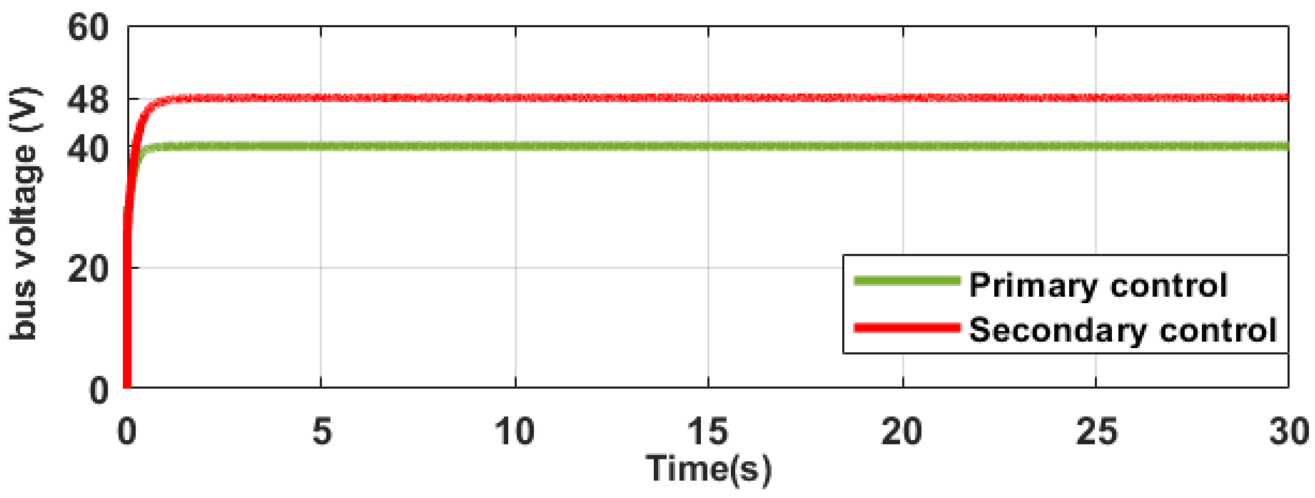
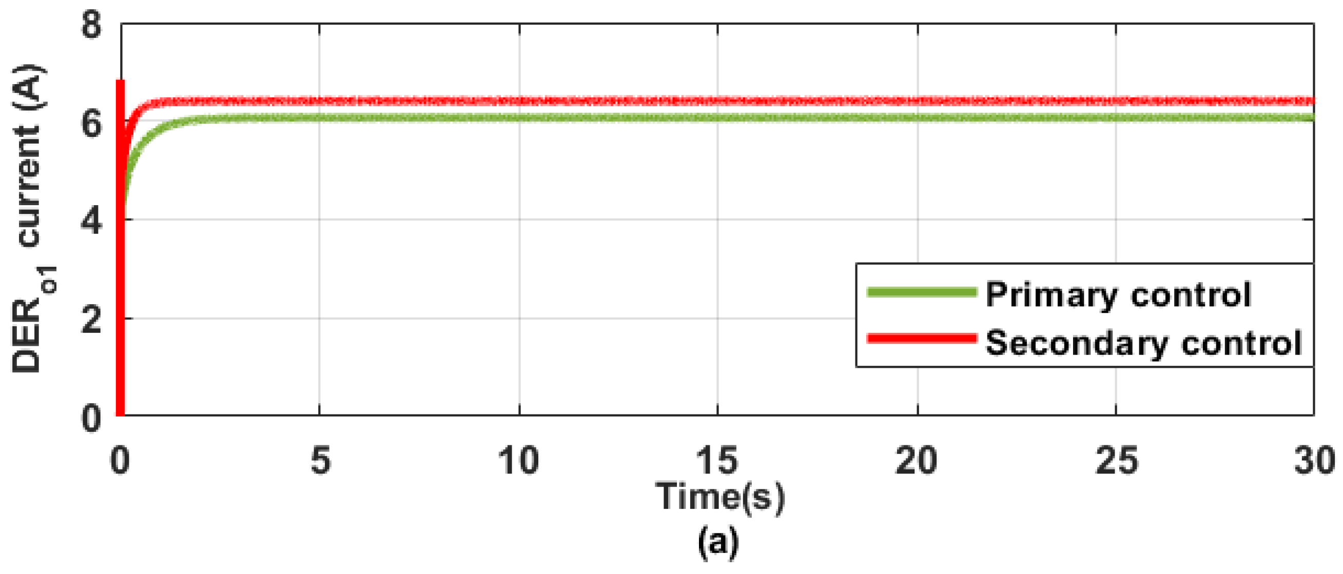
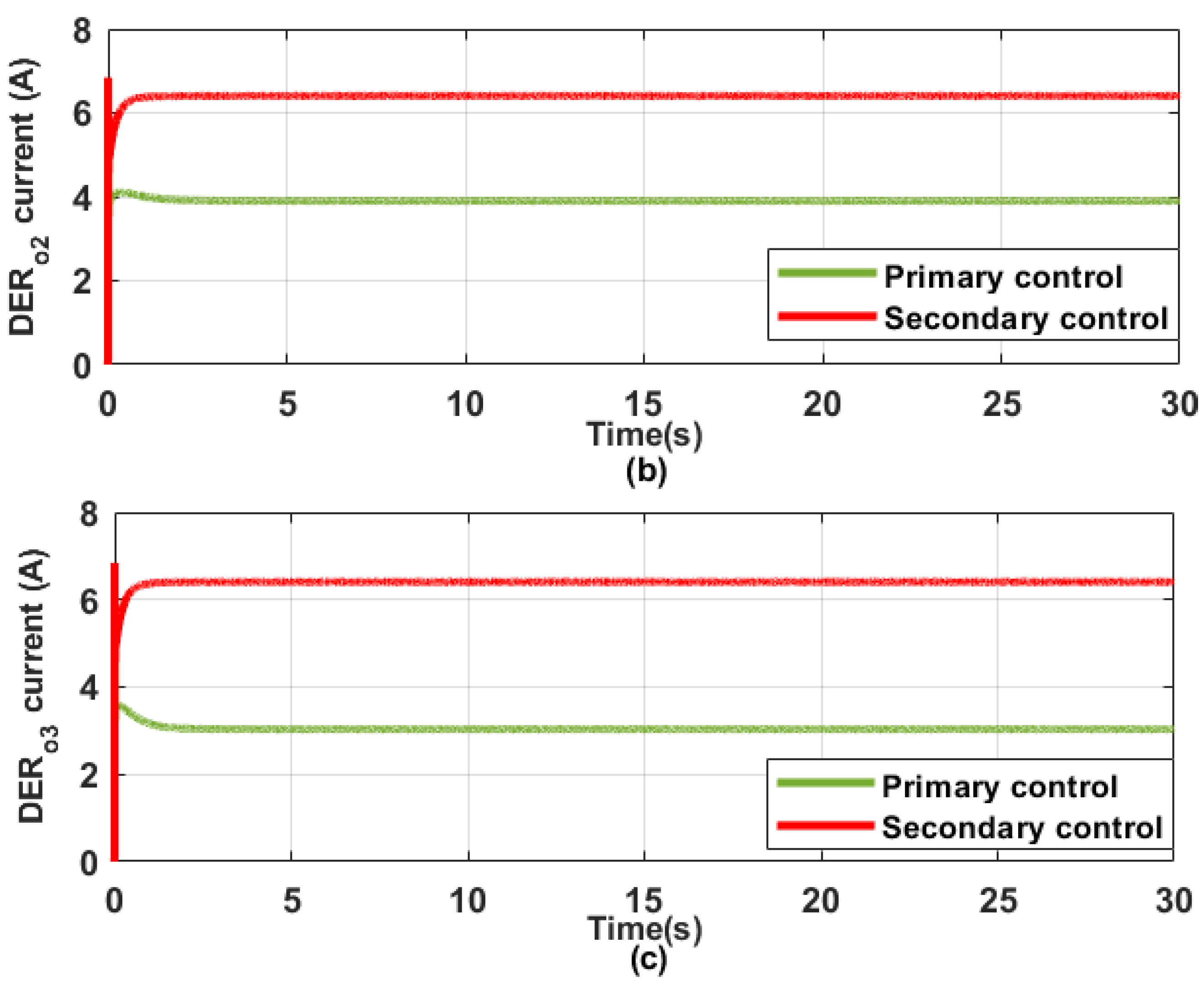
5.2. Control Objectives Realization

In this scenario, the capabilities of the newly introduced distributed control in achieving the objectives of bus voltage recovery and balanced current allocation, utilizing the DC-MG state-space model, have been examined. The DERs have been set up to evenly share the load, while the DC-MG was configured to operate at a designated bus voltage (48 V). Figure 8 depicts the MG bus voltage results. A bus voltage variation, Δ U d c , of approximately 8 V is observed when operating solely under primary control (green plot) for each active energy source. However, upon activating the proposed control, the voltage at the bus is restored to its designated value ( U d c = 48 V), significantly reducing oscillations compared to the microgrid controlled by the primary controller alone. Likewise, Figure 9 presents the output current ESs in the DC-MG. Attaining balanced current allocation among the ESs is difficult, as evidenced by the current outputs ( D E R o 3 = 3.0 A, D E R o 2 = 4.0 A, D E R o 1 = 6.0 A) presented in Figure 9a–c when operating solely under primary control. However, with the activation of the proposed secondary control, the ESs achieved consistent current allocation ( D E R o 3 = D E R o 2 = D E R o 1 = 6.4 A) over the course of the entire simulation period, as illustrated in Figure 9a–c. It can be inferred that the control goals specified in (18) and (19) for the DC-MG are being achieved effectively by the proposed distributed secondary controller.

5.3. Validation through Real-Time Experimental Simulation

This section demonstrates the robustness and effectiveness of the distributed control proposed in real-time through various practical cases, such as during communication delays and demand variations, to ascertain its performance in practical applications. For the real-time set-up, four energy resources powering both resistive and constant power loads (CPL) and resistive loads have been modelled. Each energy source is outfitted with its own converter, which includes localized control mechanisms. Moreover, the secondary control loop is developed for each energy source, enabling information sharing with neighbouring sources via a communication network. This setup establishes the distributive capabilities of the control approach. Practical cases were accurately simulated through the development of a comprehensive DC-MG model within a real-time environment, employing the Speedgoat™ Performance Real-Time machine. The Speedgoat™ simulator (Bern, Switzerland) is an advanced real-time machine designed specifically for real-time testing. It is custom-built to integrate seamlessly with MathWorks R2023b applications, such as Simulink R2023b and its real-time toolboxes. The Speedgoat™ Performance simulator is utilized for executing control algorithms designed with MATLAB/Simulink® R2023b software, hardware-in-the-loop simulations, and rapid-control prototyping. The simulator features a quad-core CPU, Intel 4.2 GHz Core i7-7700K, and an I/O318-100k reconfigurable FPGA module (Xilinx Spartan 6 100k (Bern, Switzerland)) with a clock frequency of 75 MHz. A sampling frequency of 20 kHz and 57,667 logic cells (57% of the total area of the FPGA) was utilized, consuming up to 328 mW. Matlab/Simulink® was utilized to create and evaluate the control algorithms and DC-MG model in a virtual environment. Simulink Real-Time™ and HDL Coder™ (R2023b) automatically generate codes from the DC-MG Simulink model, which are then deployed, for execution, to the Speedgoat Real-Time Performance system. The detailed parameters utilized for the system are provided in Table 4.

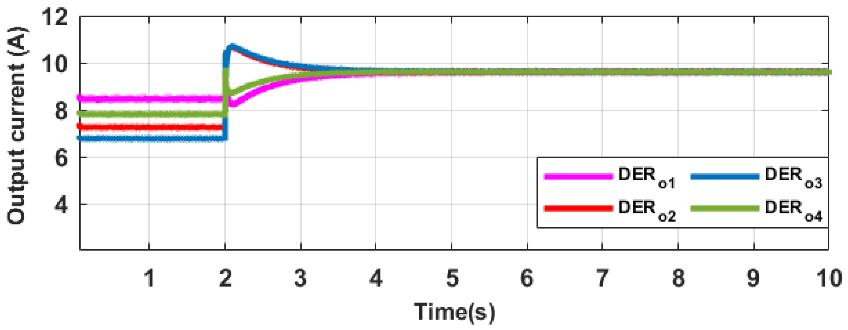
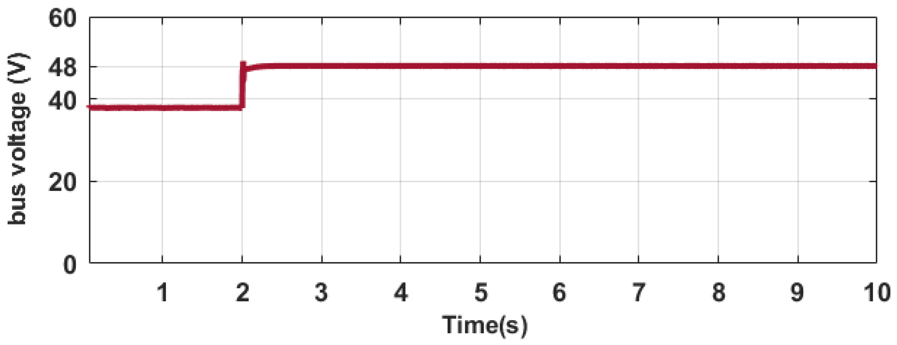
5.3.1. Current Allocation and Voltage Recovery Evaluation

Tests were performed to assess equal current distribution and voltage recovery under this case study. The primary goal is to ensure equitable current allocation, meeting the consensus objective for all ESs operating in the microgrid. Concurrently, the distributed secondary controller preserves the bus voltage at a steady-state value, which serves as the global objective. The study is divided into two scenarios. The primary control system alone was active in the first phase t [ 0 , 2 ) for each energy source, with the inclusion of loads R L 1 and R L 2 . In the final phase t ( 2 , 10 ] , the secondary control is enabled across all ESs. This step involves implementing the advanced control strategy throughout the system, enhancing coordination and performance. A detailed depiction of the simulation results is provided in Figure 10, Figure 11 and Figure 12, showcasing various aspects of the outcomes throughout the different stages of the analysis. Figure 10 displays the current outputs for the ESs, providing a detailed view of how each energy source contributes to the overall current distribution within the system. This visualization helps in understanding the performance and interaction of the ESs throughout the simulation. In the first phase, where only primary control is in effect, noticeable discrepancies in the current outputs are observed ( D E R o 4 = 7.80 A, D E R o 3 = 6.80 A, D E R o 2 = 7.26 A, D E R o 1 = 8.50 A). Despite the intention to achieve an equal current distribution ratio of 1:1:1:1 among the ESs, the actual current outputs vary significantly. In the second phase, following the activation of the proposed secondary control, the output current of the ESs stabilizes to a consistent value ( D E R o 4 = D E R o 3 = D E R o 2 = D E R o 1 = 9.64 A) within 1.4 s. This convergence to a consistent current level highlights the performance of the secondary control in balancing the current distribution among the ESs. Figure 11 presents the bus voltage trend over the entire period of the simulation, highlighting how the voltage levels varied throughout the different phases of the test. The first phase captured a bus voltage of 38 V, which represents a 10 V variation from the designated voltage level. This variation reflects the system’s performance under the primary droop control alone. However, once the proposed secondary control is enabled in phase two, the variation is corrected within 0.4 s, with a 2.5% overshoot, and the bus voltage is restored to its target value (48 V). At t = 2 s, the activation of the proposed secondary control within each energy source clearly demonstrates the achievement of the control objectives. This is vividly displayed in Figure 12, which shows how the secondary control effectively meets the desired performance criteria and stabilizes the system. Under these circumstances, the secondary control signals are generated for each DER, enabling coordination with neighbouring ESs. This facilitates consensus in current allocation and effective global bus voltage recovery.

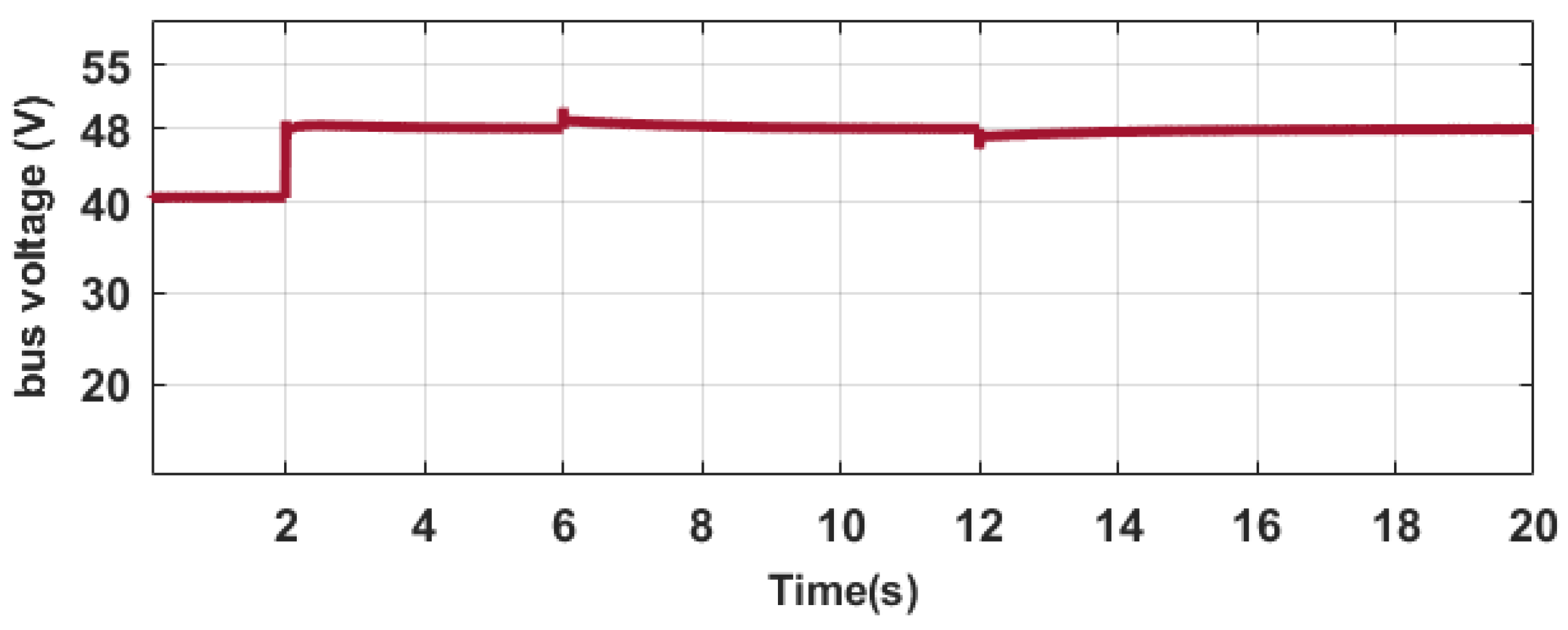
5.3.2. Performance of Proposed Secondary Control during Varying Power Demand

This section examines another practical case study through real-time analysis. Using the same communication topology as described in the prior section, this analysis evaluates changes in power flow to examine the distributed features of the distributed control. An additional load, constant power load (CPL), R C P L , is connected to the DC bus. The simulation for this case study is conducted over a 20 s period, divided into distinct operational phases. From t [ 0 , 2 ) , only the primary droop controller within each energy source is enabled, operating alongside CPL, R C P L , as well as resistive loads R L 1 and R L 2 . At t = 2 s, the proposed secondary controllers for each energy source are activated and come into effect during the interval t ( 6 , 12 ) . This staged approach allows for a detailed examination of the system’s response before and after the introduction of the proposed secondary control. At t = 6 s, within the interval t ( 6 , 12 ) , R C P L is disconnected from the bus. Then, within the period t ( 12 , 20 ] , R C P L is reconnected to the bus at t = 12 s. This sequence allows for an assessment of how the system manages load disconnections and reconnections, providing insights into its performance and stability under varying load conditions. Figure 13, Figure 14 and Figure 15 presents the obtained results from this case study. Figure 13 illustrates that equitable current allocation is achieved when the secondary control is activated at t = 2 s. Upon the disconnection of the load at t = 6 s, the output current of the energy resources decreases from 6.65 A to 5.88 A. This is accompanied by a brief transient, with DER 1 experiencing a slight undershoot of 5.61%. Nevertheless, within just 0.4 s, the DERs smoothly achieve real-time consensus operation, maintaining the stability of the microgrid’s communication protocol without any disruption. Additionally, when the load is reconnected at t = 12 s, the energy sources continue to sustain their concise current allocation properties without any disruption. The energy sources encounter an increase in output current from 5.88 A to 6.65 A, with a brief transient during which DER 1 shows a 4.77% peak current overshoot. Despite this, the system achieves consensus within 0.4 s. An analysis of the bus voltage, shown in Figure 14, reveals a sudden spike in voltage occurring at the moment the load is disconnected. However, this transient spike is quickly mitigated within 0.7 s, bringing the bus voltage back to its steady-state value with a 6.25% overshoot. This rapid stabilization ensures the microgrid remains stable. Similarly, when the load is reconnected at t = 12 s, a noticeable drop in the bus voltage occurs. However, this drop in voltage is quickly addressed within 0.6 s, with a 4.16% undershoot, and the voltage is restored to its steady-state level. This rapid recovery is achieved through the voltage control mechanism of the proposed distributed control system described in this article. As shown in Figure 15, the control signals responded quickly and effectively, achieving the control objectives at the required intervals. It can be concluded that the secondary control developed in this research preserves the distributed feature of the microgrid, even amidst fluctuations in power flow, without a disruption in the communication topology. Comparable results were observed in prior studies [26,27,29], where the effectiveness of their proposed methods was assessed through various modifications in resistive and constant power loads.

5.3.3. Performance of Secondary Control during Communication Delay

Communication links play a crucial role in enabling secondary distributed controls to function, facilitating their interaction and data exchange in the MG. This interaction is pivotal for accomplishing the prescribed control objectives. Therefore, it is crucial to assess the impact of communication delays on the performance of the distributed controller proposed in this study. Using the near-neighbour communication topology detailed in Section 3.1, the study investigated the effects of various time delays among the secondary controls. The communication links a 12 , a 13 , and a 34 are configured with time delays of 150 ms, 200 ms, and 250 ms, respectively. The real-time simulation encompassed three stages over a total duration of 10 s. The first stage spans from t [ 0 , 3 ) , and both the secondary and primary controls for the ESs are enabled at t = 0 s, alongside the loads R L 1 and R C P L . During stage two, which takes place from t ( 3 , 7 ) , an additional load, R L 2 , is introduced at t = 3 s. In the final stage, spanning from t ( 7 , 10 ] , this load is disconnected at t = 7 s, marking the conclusion of the simulation. Figure 16, Figure 17 and Figure 18 present the obtained results from this case study. From the analysis presented in Figure 16, it is evident that during stage one, there is noticeable variability in the start times of the current outputs from the energy sources. This variation arises due to the differing time delays incorporated into the communication protocol of the DC-MG. Despite these variations, the distributed secondary controller developed in this study ensures that consensus in current allocation is achieved swiftly, within a timeframe of under 0.6 s. This control mechanism effectively synchronizes the DERs, overcoming the challenges posed by communication delays. Similarly, when the load is introduced during stage two and subsequently disconnected in the final stage, the output current from each energy source adjusts accordingly in both situations. This dynamic adjustment ensures that the DERs effectively align with the changing power demands throughout the simulation. The output current responses reflect the influence of communication delays, but overall, the total current demand is consistently distributed across the energy sources. Despite the individual variations caused by delays, the distribution of current among the DERs remains balanced.
Additionally, Figure 17 illustrates the bus voltage for this specific case study. In contrast to the variations observed in output current, the impact of communication delays on the bus voltage is not apparent. This difference occurs because the voltage restoration goal is global, meaning it only requires intervention from a single operational energy source to maintain the desired voltage level. In contrast, the current allocation goal is based on achieving consensus, which requires active participation and coordination from all operational energy sources in the DC-MG. Figure 18 illustrates the control signals, highlighting the control actions executed by the distributed secondary controller. It is clear that each secondary control mechanism effectively responds to meet the control goals. This ensures that the bus voltage remains stabilized at its rated value while also achieving appropriate load current allocation within the DC-MG. Therefore, we can conclude that the proposed distributed controller provides significant benefits by facilitating system recovery, even in the presence of communication delays. This advantage highlights its robustness and effectiveness in maintaining system stability despite latency issues.
In real-world DC microgrids, particularly in isolated locations, enhanced voltage recovery and current sharing play critical roles in improving both dependability and effectiveness. In isolated microgrids, voltage fluctuations can lead to instability and interruptions in power supply. Enhanced voltage recovery helps to quickly restore stable voltage levels after disturbances, such as load changes or faults, ensuring a continuous power supply. Voltage recovery mechanisms help protect sensitive equipment from damage caused by sudden voltage drops or spikes, which is especially crucial in remote areas where equipment repair and replacement may be challenging. Fast voltage recovery reduces the duration of outages, minimizing downtime and ensuring that the microgrid remains operational even after transient faults. Proper current sharing ensures that loads are evenly distributed among multiple sources (e.g., solar panels, batteries) or parallel converters. This prevents the overloading of individual components, extending their lifespan and reducing the risk of failures. By balancing the current among all power sources, current sharing improves the overall efficiency of the microgrid. This is particularly important in isolated areas where maximizing the use of available energy resources is essential. Current sharing allows for easy integration of additional power sources without significantly altering the system’s existing setup, making the microgrid more adaptable to changing energy needs or expansions. Additionally, by preventing any single source or converter from being overburdened, current sharing enhances the overall reliability of the microgrid, reducing the likelihood of component failures that could disrupt power supply.

5.4. Comparison with Alternative Secondary Distributed Control Methods

A detailed evaluation of the response times for the newly introduced distributed secondary controller in achieving its control goals, as discussed in Section 5.3.1, is provided in this section. This assessment is compared to the performance of other dual-loop secondary control (current and voltage each) techniques presented in previous studies. The selected control methods aim for the same goals as those considered in our research, such as equitable current allocation and voltage restoration, though they vary in the configuration of their control system and control coefficients. The conventional secondary control method (M1), utilizing a trial-and-error approach for tuning the control coefficients, model predictive secondary control (M2) [44], consensus secondary control (M4) [24], enhanced consensus-based secondary control (M5) [25], improved consensus-based with heterogeneous communication time delays (M6) [22], and supervisory secondary control (M3) [27]. A summary of the comparative results between the various alternative control methods and proposed methods is presented in Table 5. The control metrics chosen for comparison are aligned with the methodology adopted in this research. Key metrics include voltage recovery and current allocation, which directly relate to the problem statement of this study. Additionally, standard control system metrics like robustness and implementation complexity are considered. Other metrics, such as scalability and communication type, are identified as potential areas for exploration in future research. Analysing the data shown in Table 5, it is observed that the proposed method outperforms M6. Specifically, it achieves a 33% decrease in time response for equitable current allocation and a 64% reduction in time response for restoring bus voltage. In comparison to M5, the proposed method demonstrates a 13% decrease in time response for balanced current allocation and also achieves a 60% reduction in time response for quickly restoring the bus voltage to its nominal value. It can also be observed that the proposed method outperforms M4. Specifically, it achieves a 60% decrease in time response for equitable current allocation and an 87% reduction in time response for restoring bus voltage. In comparison to M2, the proposed method demonstrates a 7% decrease in time response for balanced current allocation and also achieves a 70% reduction in time response for quickly restoring the bus voltage to its nominal value. In addition, the proposed controller outperforms M3, improving the time response for achieving balanced current allocation by 43% and reducing the time required to restore bus voltage to its nominal value by 77%. In comparison to M1, the proposed method demonstrates a 50% decrease in time response for balanced current allocation and also achieves an 80% reduction in time response for quickly restoring the bus voltage to its nominal value. It is noteworthy that the control goal of voltage recovery is achieved more rapidly compared to the objective of current allocation. The disparity in time responses is due to the fact that achieving consensus for current allocation requires extensive communication and coordination among the energy sources. In contrast, the voltage recovery objective demands less communication effort, leading to quicker time response for voltage adjustments.
In summary, the proposed HPSO–GWO method in secondary distributed control for microgrids demonstrates superior performance in current allocation, voltage recovery, and settling time across various conditions. This is attributed to its significant advantages in exploration, exploitation, and robustness, making it an effective tool for optimizing control parameters in DC microgrids. However, the hybrid algorithm is more complex than using PSO or GWO alone, which can lead to increased computational requirements. The performance of the hybrid algorithm can be sensitive to the choice of parameters such as the number of particles, wolves, and the weights associated with each component. Tuning these parameters can be challenging and time-consuming, while hybridization generally improves convergence, there is still a risk of premature convergence, especially if the balance between exploration and exploitation is not well-maintained. Additionally, In a distributed controller environment, the hybrid algorithm may introduce additional communication overhead, particularly in real-time applications. This can affect the overall efficiency of the control system.

6. Conclusions

This article introduces an advanced distributed secondary control method aimed at optimizing current allocation among multiple energy resources while simultaneously ensuring voltage recovery in a DC microgrid (DC-MG). The control method utilizes an integral control technique, with its design parameters determined by employing a hybrid Particle Swarm Optimization and Grey Wolf Optimization (HPSO-GWO) algorithm. The HPSO-GWO algorithm aims to minimize both the voltage variation and current allocation error within the DC-MG. This dual-objective function ensures optimal performance of the control system. This control technique is robust and offers advantages owing to its adaptability stemming from its tuning procedure. The performance of the designed control is evaluated utilizing both the state-space and physical models of the DC-MG, while the stability of the proposed control is assessed through eigenvalue analysis. To assess and confirm the efficacy and robustness of the proposed control system in meeting the control objectives of the DC-MG, real-time experiments are conducted using the Speedgoat™ Performance machine. The results demonstrated that the proposed secondary control effectively achieved enhanced voltage recovery and proper current distribution, ensuring a continuous power supply, even after various disturbances were considered. The results also reveal that the secondary controller achieves the control objectives within an autonomous DC-MG. Specifically, it delivers a 50% decrease in time response for optimizing current allocation and an 80% reduction in time response for restoring the bus voltage to its steady-state value, compared to the conventional controller. Thus, implementing the proposed distributed controller in DC-MGs provides a robust solution for addressing issues related to voltage restoration and ensuring fair current allocation. This approach offers practical benefits for real-world applications by effectively managing these critical challenges. Future research could extend to investigating the performance of the proposed approach under a broader range of load conditions, including dynamic and non-linear loads. Additionally, implementing the algorithm in systems with hybrid energy resources, such as combinations of solar, wind, and battery storage, could provide deeper insights into its versatility and effectiveness. Exploring various converter configurations, including different topologies and control schemes, would further enhance the understanding of how the algorithm adapts to diverse microgrid architectures, potentially leading to more robust and scalable solutions. Furthermore, exploring additional evolutionary metaheuristic algorithms could enhance the performance of the controller.

Author Contributions

Conceptualization, O.L., A.A. and A.S.; methodology, A.A., O.L. and A.S.; software, A.S., O.L., M.K. and A.A.; validation, A.S., A.A., M.K. and L.J.; formal analysis, M.K., A.S., O.L. and A.A.; resources, M.K., L.J. and A.S.; writing—original draft preparation, A.A., M.K., O.L. and A.S.; writing—review and editing, O.L., A.S. and L.J.; visualization, O.L., M.K. and A.S.; supervision, A.S. and L.J.; project administration, A.S.; funding acquisition, A.S. and L.J. All authors have read and agreed to the published version of the manuscript.

Funding

This research received no external funding.

Institutional Review Board Statement

Not applicable.

Informed Consent Statement

Not applicable.

Data Availability Statement

No new data were created or analysed in this study. Data sharing is not applicable to this article.

Acknowledgments

The authors express their gratitude to the Center for Power and Energy Systems at UKZN for their technical support throughout the study period.

Conflicts of Interest

Author Anuoluwapo Aluko was employed by the company Enerzix, LLC. The remaining authors declare that the research was conducted in the absence of any commercial or financial relationships that could be construed as a potential conflict of interest.

Abbreviations

The following abbreviations are used in this manuscript:
RESsRenewable Energy Sources
DC-MGDC Microgrid
MGsMicrogrids
ACAlternating Current
ESsEnergy Sources
MHOMeta-Heuristic Optimization
PSOParticle Swarm Optimization
GWOGrey Wolf Optimization
HPSO-GWOHybrid Particle Swarm Optimization-Grey Wolf Optimization
S-SState-Space
CPLConstant Power Load
DCDirect Current
DERsDistributed Energy Resources

References

  1. Al-Tameemi, Z.H.A.; Lie, T.T.; Foo, G.; Blaabjerg, F. Optimal Coordinated Control of DC Microgrid Based on Hybrid PSO–GWO Algorithm. Electricity 2022, 3, 346–364. [Google Scholar] [CrossRef]
  2. Abhishek, A.; Ranjan, A.; Devassy, S.; Kumar Verma, B.; Ram, S.K.; Dhakar, A.K. Review of hierarchical control strategies for DC microgrid. IET Renew. Power Gener. 2020, 14, 1631–1640. [Google Scholar] [CrossRef]
  3. Gholami, M.; Pisano, A. Model Predictive Operation Control of Islanded Microgrids under Nonlinear Conversion Losses of Storage Units. Electricity 2022, 3, 33–50. [Google Scholar] [CrossRef]
  4. Ali, S.; Shengxue, T.; Jianyu, Z.; Ali, A.; Nawaz, A. An implementation of parallel buck converters for common load sharing in DC microgrid. Information 2019, 10, 91. [Google Scholar] [CrossRef]
  5. Rezaei, O.; Mirzapour, O.; Panahazari, M.; Gholami, H. Hybrid AC/DC provisional microgrid planning model considering converter aging. Electricity 2022, 3, 236–250. [Google Scholar] [CrossRef]
  6. Al-Ismail, F.S. DC microgrid planning, operation, and control: A comprehensive review. IEEE Access 2021, 9, 36154–36172. [Google Scholar] [CrossRef]
  7. Aluko, A.; Buraimoh, E.; Oni, O.E.; Davidson, I.E. Advanced distributed cooperative secondary control of Islanded DC Microgrids. Energies 2022, 15, 3988. [Google Scholar] [CrossRef]
  8. Al-Tameemi, Z.H.A.; Lie, T.T.; Foo, G.; Blaabjerg, F. Control strategies of DC microgrids cluster: A comprehensive review. Energies 2021, 14, 7569. [Google Scholar] [CrossRef]
  9. Nguyen, D.L.; Lee, H.H. A survey on cooperative control strategies for DC microgrids. Neurocomputing 2022, 486, 225–236. [Google Scholar] [CrossRef]
  10. Li, M.; Zhang, D.; Lu, S.; Tang, X.; Phung, T. Differential evolution-based overcurrent protection for DC microgrids. Energies 2021, 14, 5026. [Google Scholar] [CrossRef]
  11. Modu, B.; Abdullah, M.P.; Sanusi, M.A.; Hamza, M.F. DC-Based microgrid: Topologies, control schemes, and implementations. Alex. Eng. J. 2023, 70, 61–92. [Google Scholar] [CrossRef]
  12. Bharath, K.; Krishnan, M.M.; Kanakasabapathy, P. A review on DC microgrid control techniques, applications and trends. Int. J. Renew. Energy Res. (IJRER) 2019, 9, 1328–1338. [Google Scholar]
  13. Madurai Elavarasan, R.; Ghosh, A.; Mallick, T.K.; Krishnamurthy, A.; Saravanan, M. Investigations on performance enhancement measures of the bidirectional converter in PV–wind interconnected microgrid system. Energies 2019, 12, 2672. [Google Scholar] [CrossRef]
  14. Yaqub, R. Phasor Measurement Unit Assisted Inverter—A Novel Approach for DC Microgrids Performance Enhancement. Electricity 2021, 2, 330–341. [Google Scholar] [CrossRef]
  15. Sahoo, S.; Mishra, S.; Fazeli, S.M.; Li, F.; Dragičević, T. A distributed fixed-time secondary controller for DC microgrid clusters. IEEE Trans. Energy Convers. 2019, 34, 1997–2007. [Google Scholar] [CrossRef]
  16. Espina, E.; Llanos, J.; Burgos-Mellado, C.; Cardenas-Dobson, R.; Martinez-Gomez, M.; Saez, D. Distributed control strategies for microgrids: An overview. IEEE Access 2020, 8, 193412–193448. [Google Scholar] [CrossRef]
  17. Wan, Q.; Zheng, S. Distributed cooperative secondary control based on discrete consensus for DC microgrid. Energy Rep. 2022, 8, 8523–8533. [Google Scholar] [CrossRef]
  18. Gao, F.; Kang, R.; Cao, J.; Yang, T. Primary and secondary control in DC microgrids: A review. J. Mod. Power Syst. Clean Energy 2019, 7, 227–242. [Google Scholar] [CrossRef]
  19. Liu, X.K.; Jiang, H.; Wang, Y.W.; He, H. A distributed iterative learning framework for DC microgrids: Current sharing and voltage regulation. IEEE Trans. Emerg. Top. Comput. Intell. 2020, 4, 119–129. [Google Scholar] [CrossRef]
  20. Yuan, Q.F.; Wang, Y.W.; Liu, X.K.; Lei, Y. Distributed fixed-time secondary control for DC microgrid via dynamic average consensus. IEEE Trans. Sustain. Energy 2021, 12, 2008–2018. [Google Scholar] [CrossRef]
  21. Xing, L.; Cai, J.; Liu, X.; Fang, J.; Tian, Y.C. Distributed secondary control of DC microgrid via the averaging of virtual current derivatives. IEEE Trans. Ind. Electron. 2024, 71, 2914–2923. [Google Scholar] [CrossRef]
  22. Nguyen, D.L.; Lee, H.H. Accurate power sharing and voltage restoration in DC microgrids with heterogeneous communication time delays. IEEE Trans. Power Electron. 2022, 37, 11244–11257. [Google Scholar] [CrossRef]
  23. Guo, F.; Huang, Z.; Wang, L.; Wang, Y. Distributed event-triggered voltage restoration and optimal power sharing control for an islanded DC microgrid. Int. J. Electr. Power Energy Syst. 2023, 153, 109308. [Google Scholar] [CrossRef]
  24. Dong, M.; Li, L.; Nie, Y.; Song, D.; Yang, J. Stability analysis of a novel distributed secondary control considering communication delay in DC microgrids. IEEE Trans. Smart Grid 2019, 10, 6690–6700. [Google Scholar] [CrossRef]
  25. Mosaad, N.; Abdel-Rahim, O.; Megahed, T.F.; Rohouma, W.; Asano, T.; Abdelkader, S.M. An enhanced consensus-based distributed secondary control for voltage regulation and proper current sharing in a DC islanded microgrid. Front. Energy Res. 2023, 11, 1277198. [Google Scholar] [CrossRef]
  26. Sadabadi, M.S.; Mijatovic, N.; Dragičević, T. A Robust Cooperative Distributed Secondary Control Strategy for DC Microgrids with Fewer Communication Requirements. IEEE Trans. Power Electron. 2023, 38, 271–282. [Google Scholar] [CrossRef]
  27. Liu, X.K.; Wang, Y.W.; Lin, P.; Wang, P. Distributed supervisory secondary control for a DC microgrid. IEEE Trans. Energy Convers. 2020, 35, 1736–1746. [Google Scholar] [CrossRef]
  28. Yu, Y.; Liu, G.P.; Huang, Y.; Guerrero, J.M. Distributed learning-based secondary control for islanded dc microgrids: A high-order fully actuated system approach. IEEE Trans. Ind. Electron. 2024, 71, 2990–3000. [Google Scholar] [CrossRef]
  29. Guo, F.; Wang, L.; Wen, C.; Zhang, D.; Xu, Q. Distributed voltage restoration and current sharing control in islanded DC microgrid systems without continuous communication. IEEE Trans. Ind. Electron. 2020, 67, 3043–3053. [Google Scholar] [CrossRef]
  30. Keshta, H.E.; Saied, E.M.; Malik, O.P.; Bendary, F.M.; Ali, A.A. Fuzzy PI controller-based model reference adaptive control for voltage control of two connected microgrids. IET Gener. Transm. Distrib. 2021, 15, 602–618. [Google Scholar] [CrossRef]
  31. Gao, Z.M.; Zhao, J. An improved grey wolf optimization algorithm with variable weights. Comput. Intell. Neurosci. 2019, 2019, 2981282. [Google Scholar] [CrossRef]
  32. Hu, P.; Pan, J.S.; Chu, S.C. Improved binary grey wolf optimizer and its application for feature selection. Knowl.-Based Syst. 2020, 195, 105746. [Google Scholar] [CrossRef]
  33. Liu, J.; Wei, X.; Huang, H. An improved grey wolf optimization algorithm and its application in path planning. IEEE Access 2021, 9, 121944–121956. [Google Scholar] [CrossRef]
  34. Zhang, X.; Lin, Q.; Mao, W.; Liu, S.; Dou, Z.; Liu, G. Hybrid Particle Swarm and Grey Wolf Optimizer and its application to clustering optimization. Appl. Soft Comput. 2021, 101, 107061. [Google Scholar] [CrossRef]
  35. Shaheen, M.A.; Hasanien, H.M.; Alkuhayli, A. A novel hybrid GWO-PSO optimization technique for optimal reactive power dispatch problem solution. Ain Shams Eng. J. 2021, 12, 621–630. [Google Scholar] [CrossRef]
  36. Şenel, F.A.; Gökçe, F.; Yüksel, A.S.; Yiğit, T. A novel hybrid PSO–GWO algorithm for optimization problems. Eng. Comput. 2019, 35, 1359–1373. [Google Scholar] [CrossRef]
  37. Lasabi, O.; Swanson, A.; Jarvis, L.; Aluko, A.; Brown, M. Enhanced Distributed Non-Linear Voltage Regulation and Power Apportion Technique for an Islanded DC Microgrid. Appl. Sci. 2023, 13, 8659. [Google Scholar] [CrossRef]
  38. Zhang, N.; Yang, D.; Zhang, H.; Luo, Y. Distributed control strategy of DC microgrid based on consistency theory. Energy Rep. 2022, 8, 739–750. [Google Scholar] [CrossRef]
  39. Kaveh, A.; Zakian, P. Improved GWO algorithm for optimal design of truss structures. Eng. Comput. 2018, 34, 685–707. [Google Scholar] [CrossRef]
  40. Dahmani, S.; Yebdri, D. Hybrid algorithm of particle swarm optimization and grey wolf optimizer for reservoir operation management. Water Resour. Manag. 2020, 34, 4545–4560. [Google Scholar] [CrossRef]
  41. Almabrok, A.; Psarakis, M.; Dounis, A. Fast tuning of the PID controller in an HVAC system using the big bang–big crunch algorithm and FPGA technology. Algorithms 2018, 11, 146. [Google Scholar] [CrossRef]
  42. Ghanbari, N.; Bhattacharya, S.; Mobarrez, M. Modeling and stability analysis of a DC microgrid employing distributed control algorithm. In Proceedings of the 2018 9th IEEE International Symposium on Power Electronics for Distributed Generation Systems (PEDG), Charlotte, NC, USA, 25–28 June 2018; pp. 1–7. [Google Scholar]
  43. Lasabi, O.; Swanson, A.; Jarvis, L.; Aluko, A.; Goudarzi, A. Coordinated Hybrid Approach Based on Firefly Algorithm and Particle Swarm Optimization for Distributed Secondary Control and Stability Analysis of Direct Current Microgrids. Sustainability 2024, 16, 1204. [Google Scholar] [CrossRef]
  44. Chandrasekar, A.; Sengupta, S.; Hingane, S.; Gururaja, C.; Pandit, S. Comparative Analysis of Model Predictive Control (MPC) and Conventional Control in Supervisory Controller of a Retrofit HEV; Report 0148-7191, SAE Technical Paper; SAE International: Warrendale, PA, USA, 2017. [Google Scholar]
Figure 1. Converter equivalent circuit.
Sustainability 16 07750 g001
Figure 2. Block diagram of the converter.
Sustainability 16 07750 g002
Figure 3. DC-MG coupled with converter primary controller.
Sustainability 16 07750 g003
Figure 4. Autonomous DC-MG layouts.
Sustainability 16 07750 g004
Figure 5. Communication link in a near-neighbour fashion.
Sustainability 16 07750 g005
Figure 6. Proposed DC-MG secondary control.
Sustainability 16 07750 g006
Figure 7. Implemented HPSO-GWO flowchart.
Sustainability 16 07750 g007
Figure 8. Analysis of bus voltage using S-S methods.
Sustainability 16 07750 g008
Figure 9. Analysis of current output using S-S methods: (a) DER 1; (b) DER 2; (c) DER 3.
Sustainability 16 07750 g009aSustainability 16 07750 g009b
Figure 10. Output current of ESs.
Sustainability 16 07750 g010
Figure 11. Bus voltage.
Sustainability 16 07750 g011
Figure 12. Proposed secondary control signals.
Sustainability 16 07750 g012
Figure 13. ESs output current output during varying power demand.
Sustainability 16 07750 g013
Figure 14. Bus voltage during varying power demand.
Sustainability 16 07750 g014
Figure 15. Proposed secondary control signals during varying power demand.
Sustainability 16 07750 g015
Figure 16. Output current of individual DER during communication delays.
Sustainability 16 07750 g016
Figure 17. Bus voltage analysis during communication delays.
Sustainability 16 07750 g017
Figure 18. Control signals during communication delays.
Sustainability 16 07750 g018
Table 1. Comparison of the proposed control approach with alternative techniques.
MethodsControl Objective RealizationRobustnessScalabilityCommunication TypeImplementation Complexity
[17,27,28]goodmoderatemoderatereducedcomplex
[22,25]goodmoderatelowall-to-allsimple
[23,29]betterlowlowall-to-allsimple
[24]goodmoderatemoderatereducedsimple
[20]goodmoderatemoderatereducedcomplex
[26]goodlowhighnonecomplex
Proposed Techniqueexcellenthighmoderatereducedcomplex
Table 2. Parameters for DC-MG S-S model.
Parameters Symbols Values
Rated Bus Voltage U r 48 V
Voltage Source U s 100 V
Switching Frequency f s w 10 kHz
Converter CapacitanceC200 μF
Converter InductanceL10 mH
Load R L j j = 1 , 3 Ω , 5  Ω , 5  Ω
HPSO-GWO Algorithm Parameters
No. of search agents M S A 30
Inertia constantw0.5 + rand()/2
Max. count of iterations M N I 500
No. of design variables ρ 1
Primary Controls
Current Loop K i p , K i i 2.5, 5
Voltage Loop K v p , K v i 0.248, 2
Droop resistance R d i i = 1 , 3 Ω
Table 3. Eigenvalue analysis For DC-MG primary and secondary control.
Mode Primary   Control Secondary   Control
λ 1 −137.25− 198.70 + i347.11
λ 2 12.46 + i120.71−198.70 − i347.11
λ 3 12.46 − i120.71−6.16
λ 4 −12.76− 1.45
λ 5 −6.5 + i55.60−3.33
λ 6 −6.5 + i55.60−0.80 + i4.08
λ 7 −4.5 + i66.35−0.80 − i4.08
λ 8 −4.5 + i66.35−370.06
λ 9 −3.41−370.06
λ 10 −3.41− 0.80 + i4.08
λ 11 −0.80 − i4.08
λ 12 −3.35
λ 13 −3.35
Table 4. Real-time simulation parameters for DC-MG.
Parameters Symbols Values
Switching Frequency f s w 10 kHz
Sampling Frequency f n 20 kHz
Voltage Source U s 100 V
Nominal Bus Voltage U r 48 V
Converter InductanceL20 mH
Converter CapacitanceC120 μF
Resistive Load R L j j = 1 , 2 Ω , 6  Ω
Line Resistance R l n , i i = 1 , 4 0.3  Ω , 0.4 Ω , 0.6 Ω , 0.7 Ω
Constant Power Load R C P L 300 W
Primary Controls
Current Loop K i p , K i i 0.05, 148
Voltage Loop K v p , K v i 0.259, 38
Droop resistance R d i i = 1 , 4 Ω
Secondary Controls
Variation Coefficient for Voltage α 1.35
Variation Coefficient for Current β 7.8
Table 5. Secondary control time response analysis.
Control Objectives M 1 M 2 M 3 M 4 M 5 M 6 Proposed
Voltage Recovery2 s1.3 s1.72 s3 s1 s1.1 s≤0.4 s
Current Allocation2.8 s1.5 s2 s3.4 s1.6 s2.1 s≤1.4 s
Robustnesslowhighmoderatelowhighmoderatevery high
Implementation Complexitysimplecomplexsimplesimplecomplexcomplexcomplex
Disclaimer/Publisher’s Note: The statements, opinions and data contained in all publications are solely those of the individual author(s) and contributor(s) and not of MDPI and/or the editor(s). MDPI and/or the editor(s) disclaim responsibility for any injury to people or property resulting from any ideas, methods, instructions or products referred to in the content.

